JP4735325B2 - Control drive circuit for electric tools - Google Patents
Control drive circuit for electric toolsDownload PDFInfo
- Publication number
- JP4735325B2 JP4735325B2JP2006051104AJP2006051104AJP4735325B2JP 4735325 B2JP4735325 B2JP 4735325B2JP 2006051104 AJP2006051104 AJP 2006051104AJP 2006051104 AJP2006051104 AJP 2006051104AJP 4735325 B2JP4735325 B2JP 4735325B2
- Authority
- JP
- Japan
- Prior art keywords
- circuit
- switching element
- drive circuit
- switch
- power supply
- Prior art date
- Legal status (The legal status is an assumption and is not a legal conclusion. Google has not performed a legal analysis and makes no representation as to the accuracy of the status listed.)
- Active
Links
Images


Classifications
- H—ELECTRICITY
- H02—GENERATION; CONVERSION OR DISTRIBUTION OF ELECTRIC POWER
- H02M—APPARATUS FOR CONVERSION BETWEEN AC AND AC, BETWEEN AC AND DC, OR BETWEEN DC AND DC, AND FOR USE WITH MAINS OR SIMILAR POWER SUPPLY SYSTEMS; CONVERSION OF DC OR AC INPUT POWER INTO SURGE OUTPUT POWER; CONTROL OR REGULATION THEREOF
- H02M1/00—Details of apparatus for conversion
- H02M1/08—Circuits specially adapted for the generation of control voltages for semiconductor devices incorporated in static converters
- H—ELECTRICITY
- H03—ELECTRONIC CIRCUITRY
- H03K—PULSE TECHNIQUE
- H03K17/00—Electronic switching or gating, i.e. not by contact-making and –breaking
- H03K17/51—Electronic switching or gating, i.e. not by contact-making and –breaking characterised by the components used
- H03K17/56—Electronic switching or gating, i.e. not by contact-making and –breaking characterised by the components used by the use, as active elements, of semiconductor devices
- H03K17/687—Electronic switching or gating, i.e. not by contact-making and –breaking characterised by the components used by the use, as active elements, of semiconductor devices the devices being field-effect transistors
- H03K17/6871—Electronic switching or gating, i.e. not by contact-making and –breaking characterised by the components used by the use, as active elements, of semiconductor devices the devices being field-effect transistors the output circuit comprising more than one controlled field-effect transistor
- H—ELECTRICITY
- H03—ELECTRONIC CIRCUITRY
- H03K—PULSE TECHNIQUE
- H03K17/00—Electronic switching or gating, i.e. not by contact-making and –breaking
- H03K17/51—Electronic switching or gating, i.e. not by contact-making and –breaking characterised by the components used
- H03K17/56—Electronic switching or gating, i.e. not by contact-making and –breaking characterised by the components used by the use, as active elements, of semiconductor devices
- H03K17/687—Electronic switching or gating, i.e. not by contact-making and –breaking characterised by the components used by the use, as active elements, of semiconductor devices the devices being field-effect transistors
- H03K17/6877—Electronic switching or gating, i.e. not by contact-making and –breaking characterised by the components used by the use, as active elements, of semiconductor devices the devices being field-effect transistors the control circuit comprising active elements different from those used in the output circuit
- H—ELECTRICITY
- H02—GENERATION; CONVERSION OR DISTRIBUTION OF ELECTRIC POWER
- H02M—APPARATUS FOR CONVERSION BETWEEN AC AND AC, BETWEEN AC AND DC, OR BETWEEN DC AND DC, AND FOR USE WITH MAINS OR SIMILAR POWER SUPPLY SYSTEMS; CONVERSION OF DC OR AC INPUT POWER INTO SURGE OUTPUT POWER; CONTROL OR REGULATION THEREOF
- H02M1/00—Details of apparatus for conversion
- H02M1/0003—Details of control, feedback or regulation circuits
- H02M1/0006—Arrangements for supplying an adequate voltage to the control circuit of converters
- H—ELECTRICITY
- H03—ELECTRONIC CIRCUITRY
- H03K—PULSE TECHNIQUE
- H03K17/00—Electronic switching or gating, i.e. not by contact-making and –breaking
- H03K17/08—Modifications for protecting switching circuit against overcurrent or overvoltage
- H03K17/081—Modifications for protecting switching circuit against overcurrent or overvoltage without feedback from the output circuit to the control circuit
- H03K17/0812—Modifications for protecting switching circuit against overcurrent or overvoltage without feedback from the output circuit to the control circuit by measures taken in the control circuit
- H03K17/08122—Modifications for protecting switching circuit against overcurrent or overvoltage without feedback from the output circuit to the control circuit by measures taken in the control circuit in field-effect transistor switches
Landscapes
- Engineering & Computer Science (AREA)
- Power Engineering (AREA)
- Portable Power Tools In General (AREA)
- Inverter Devices (AREA)
- Control Of Motors That Do Not Use Commutators (AREA)
- Control Of Direct Current Motors (AREA)
- Stopping Of Electric Motors (AREA)
Description
Translated fromJapanese本発明は電動工具における制御駆動回路に関するものである。 The present invention relates to a control drive circuit in a power tool.
モータを動力源とするとともに二次電池を電源部とする電動工具に関し、そのモータ駆動について各種の制御駆動回路が提供されている(特許文献1参照)。 With respect to an electric tool that uses a motor as a power source and a secondary battery as a power source, various control drive circuits are provided for driving the motor (see Patent Document 1).
そして近年においては、耐振動の向上や耐久性の向上などを目的として電源部からモータに至るまでの回路中に機械的接点を無くすとともに、二次電池の無用な消耗を避けるためにトリガースイッチのオン操作で制御回路に通電され、トリガースイッチがオフとなれば制御回路に電源が供給されなくなるようにしたものが提供されている。 In recent years, for the purpose of improving vibration resistance and durability, there is no mechanical contact in the circuit from the power supply unit to the motor, and the trigger switch is used to avoid unnecessary consumption of the secondary battery. There is provided a control circuit in which power is not supplied to the control circuit when the control circuit is energized by an on operation and the trigger switch is turned off.
図3に一例を示す。図中Dは複数の二次電池セルを直列接続した電池パック、CPUは1チップマイクロコンピュータからなる制御回路、SW1はトリガースイッチであり、ここではモータとして巻線がブリッジ接続されているブラシレスモータを用いている。図中のU,V,Wはモータの各巻線への接続点を示しており、これら巻線へは各相の上段用のスイッチング素子F1,F3,F5及び各相の下段用のスイッチング素子F2,F4,F6を通じて給電される。図中3は上記上段のスイッチング素子用ドライブ回路、4は上記下段のスイッチング素子用ドライブ回路であり、図中のV・3,W・3及びV・4,W・4は制御回路CPUとV・W相の各ドライブ回路3,4との接続を示す。 An example is shown in FIG. In the figure, D is a battery pack in which a plurality of secondary battery cells are connected in series, CPU is a control circuit composed of a one-chip microcomputer, SW1 is a trigger switch, and here a brushless motor whose winding is bridge-connected as a motor. Used. U, V, and W in the figure indicate connection points to the respective windings of the motor, and these windings include switching elements F1, F3, F5 for the upper stages of the respective phases and switching elements F2 for the lower stages of the respective phases. , F4, F6. In the figure,
トリガースイッチSW1をオンとすれば、制御回路CPUに電源が供給され、制御回路CPUの出力で例えばトランジスタQ6,Q7,Q8で構成されるU相のスイッチング素子用ドライブ回路3でスイッチング素子F1がオンとなる時、V相下段のスイッチング素子用ドライブ回路4でスイッチング素子F4がオンとなり、次にV相のスイッチング素子駆動回路3でスイッチング素子F3がオンとなる時、W相下段のスイッチング素子用ドライブ回路4でスイッチング素子F6がオンとなり、更にW相のスイッチング素子駆動回路3でスイッチング素子F5がオンとなる時、トランジスタQ9,Q10,Q11で構成されるU相下段のスイッチング素子用ドライブ回路4でスイッチング素子F2がオンとなることで、3相モータの駆動がなされる。なお、各ドライブ回路3は昇圧回路5を通じて経て給電される。また、上記各スイッチング素子F1〜F6に逆並列接続されたダイオードは給電オフによるモータ停止時に制動がかかるようにするためのものであり、このためにトリガースイッチSW1のオフの後もしばらくは制御回路CPUにも電源が供給されるように自己保持用のトランジスタQ1,Q2を設けている。 When the trigger switch SW1 is turned on, power is supplied to the control circuit CPU, and the switching element F1 is turned on in the output circuit of the control circuit CPU by the U-phase switching
ここにおいて、トリガースイッチSW1をオフとして停止させる時、上記ドライブ回路3,4の電源遮断が制御回路CPUの電源遮断よりも先になされるようになっている時は問題ないのであるが、制御回路CPUへの電源遮断が先になされる時、制御回路CPUの出力がLowとなった時にドライブ回路4がオン(U相についてはトランジスタQ11,Q10がHi)となるためにスイッチング素子F2が導通することになり、この時、昇圧回路5を介して接続されたドライブ回路3で駆動されるスイッチング素子F1も導通状態にあることから、ブリッジ構造のスイッチング素子に貫通電流が流れることになり、スイッチング素子が破壊してしまう。他の相のスイッチング素子も同じである。
本発明は上記の従来の問題点に鑑みて発明したものであって、ブリッジ構造となっているスイッチング素子の破壊を招くことがない電動工具用制御駆動回路を提供することを課題とするものである。 The present invention has been invented in view of the above-described conventional problems, and it is an object of the present invention to provide a control drive circuit for an electric tool that does not cause destruction of a switching element having a bridge structure. is there.
上記課題を解決するために本発明に係る電動工具用制御駆動回路は、スイッチング素子とモータ本体とからなるブリッジ構造のモータが電源部に機械的接点を介することなく接続されているとともに、上記スイッチング素子の制御用の制御回路がトリガースイッチ入力で電源供給されるものにおいて、上記スイッチング素子の駆動用のドライブ回路の電源供給側に該ドライブ回路への電源供給遮断用であり且つ上記制御回路により制御される回路スイッチを設けて、上記制御回路への電源供給の遮断が上記回路スイッチの遮断後に行われるものとしていることに特徴を有している。In order to solve the above problems, a control drive circuit for an electric tool according to the present invention includes a bridge-structure motor including a switching element and a motor body connected to a power supply unit without a mechanical contact, and the switching In the case where the control circuit for controlling the element is supplied with power by the trigger switch input, the power supply side of the drive circuit for driving the switching element is for cutting off the power supply to the drive circuit and controlled by the control circuit The circuit switch is provided, and the power supply to the control circuit is cut off after the circuit switch is cut off .
ドライブ回路の不用意なオン動作がなくなるために制御回路の電源遮断によってスイッチング素子に貫通電流が流れるような状態になることがないようにしたものである。 Since the drive circuit is not inadvertently turned on, the control circuit is prevented from being turned on so that a through current does not flow through the switching element.
また、制御回路への電源投入後に上記回路スイッチがオンとなるものであることが好ましい。電源投入時に貫通電流が流れる虞もなくなる。 The circuit switch is preferably turned on after power is supplied to the control circuit. There is no risk of through current flowing when the power is turned on.
更に上記回路スイッチはブリッジ構造における上段又は下段のどちらか一方に設ければ、回路スイッチの定格が低くて済み、両方に設ければ、いずれかのスイッチング素子がショートした場合においても貫通電流が流れることがない。 Furthermore, if the circuit switch is provided in either the upper stage or the lower stage of the bridge structure, the rating of the circuit switch may be low, and if it is provided in both, a through current flows even if one of the switching elements is short-circuited. There is nothing.
上記回路スイッチは、モータオフ時のブレーキ動作時間後に遮断されるものであると、ブレーキ動作を確実に得ることができる。 If the circuit switch is cut off after the brake operation time when the motor is off, the brake operation can be reliably obtained.
そして上記回路スイッチはダイオードが逆並列に接続されたものであると、スイッチング素子がFETである時に水分によってDS−GD間に電圧が出て半オンしても、発生した電圧を逃がすことができるためにスイッチング素子が破壊してしまうことがない。 When the diode is connected in antiparallel, the circuit switch can release the generated voltage even if the voltage is generated between the DS and GD due to moisture when the switching element is an FET and is turned on halfway. Therefore, the switching element is not destroyed.
本発明は、スイッチング素子の駆動用のドライブ回路の電源供給側に設けた回路スイッチを備える上に、回路スイッチを制御する制御回路への電源供給の遮断が上記回路スイッチの遮断後に行われるために、電源遮断時にスイッチング素子に貫通電流が流れることがなく、このためにスイッチング素子の貫通電流による破壊を招くことがないものである。The present invention,on havinga circuit switch provided on the power supply side of the drive circuit for driving the switchingelement, in orderto cut off the power supply to the control circuit for controlling the circuit switch is performed after interruption of the circuit switch The through current does not flow through the switching element when the power is cut off, and therefore, the destruction due to the through current of the switching element is not caused.
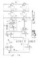
以下、本発明を添付図面に示す実施形態に基いて説明すると、図1にその一例を示す。基本的構成は図3に示した前記従来例と同じであることから説明を省略するが、ブリッジ構造となっているスイッチング素子F1〜F6の各駆動用のドライブ回路3,4の電源供給側に回路スイッチ(トランジスタ)Q4を挿入している。この回路スイッチQ4は、制御回路CPUの出力でトランジスタQ5を介してオンオフするもので、そのオフ時には各ドライブ回路3,4への電源供給を遮断する。 Hereinafter, the present invention will be described based on an embodiment shown in the accompanying drawings. FIG. 1 shows an example thereof. Since the basic configuration is the same as that of the conventional example shown in FIG. 3, a description thereof will be omitted, but on the power supply side of the
そして、トリガースイッチSW1をオンとすることで、制御回路CPUに電源が投入された時、上記回路スイッチQ4は制御回路CPUの出力でオンとなり、その後、ドライブ回路3,4及びスイッチング素子F1〜F6が制御駆動されることによるモータ駆動がなされる。 By turning on the trigger switch SW1, when the control circuit CPU is powered on, the circuit switch Q4 is turned on at the output of the control circuit CPU, and then the
トリガースイッチSW1をオフとした時には、自己保持用トランジスタQ2を介してしばし制御回路CPUに電源が供給されるが、この時、制御回路CPUは下段スイッチング素子F2,F4,F6をドライブ回路4を介して短時間(50ms〜200ms)だけオンとしてブレーキ動作を行わせ、その後、1ms〜100ms後に回路スイッチQ4をオフとしてドライブ回路3,4への給電を遮断することで、スイッチング素子に貫通電流が流れることを阻止する。なお、制御回路CPUへの電源遮断そのものは回路スイッチQ4のオフ動作後(たとえば1ms〜100ms後)になされるようにしている。 When the trigger switch SW1 is turned off, power is supplied to the control circuit CPU for a while via the self-holding transistor Q2. At this time, the control circuit CPU passes the lower switching elements F2, F4, and F6 through the
回路スイッチQ4に逆並列で接続したダイオードは、次の場合のスイッチング素子F1〜F6の破壊を防ぐためのものである。すなわち、電動工具は雨中などで使用されることもあるために、水滴が付着することでFETであるスイッチング素子のDS GD間に電圧が出て半オン状態になることがある。この電圧を逃がすことができないとスイッチング素子が破壊されることになるが、上記ダイオードがある場合、上記電圧は上記ダイオードを通じて逃がすことができる。 The diode connected in antiparallel to the circuit switch Q4 is for preventing the switching elements F1 to F6 from being destroyed in the following case. That is, since the electric tool may be used in the rain or the like, a voltage may be generated between the DS GD of the switching element, which is an FET, due to adhesion of water droplets, and may be in a half-on state. If this voltage cannot be released, the switching element will be destroyed. However, if there is the diode, the voltage can be released through the diode.
図示例においては、回路スイッチQ4を上段側のドライブ回路3及び下段側のドライブ回路4の両方の電源供給側に挿入することで、いずれかのスイッチング素子F1〜F6がショートした時にも貫通電流が流れないようにしたものを示したが、いずれか一方のドライブ回路3または4の電源供給側に挿入したものであってもよい。この場合、定格が半分で済むものとなる。 In the illustrated example, by inserting the circuit switch Q4 into the power supply side of both the
図2に他例を示す。これはスイッチング素子のゲート側に制御回路CPU出力でオフとなる常閉型のリレー接点Ryを接続し、制御回路CPUの電源が遮断された時にはスイッチング素子が強制オフされるようにしたものである。制御回路CPUの電源遮断後にスイッチング素子がオンとなることがないために、貫通電流が流れることがない。なお、上記リレー接点は各相のスイッチング素子のゲート側に設けている。 FIG. 2 shows another example. In this case, a normally closed relay contact Ry that is turned off by the output of the control circuit CPU is connected to the gate side of the switching element, and the switching element is forcibly turned off when the power supply of the control circuit CPU is cut off. . Since the switching element is not turned on after the power supply of the control circuit CPU is cut off, no through current flows. The relay contact is provided on the gate side of each phase switching element.
図示例ではブリッジ構造のモータとしてブラシレスモータを示したが、DCモータであってもよいのはもちろんである。 In the illustrated example, a brushless motor is shown as a bridge-structured motor, but a DC motor may be used.
3 ドライブ回路
4 ドライブ回路
CPU 制御回路
D 電源部
F1〜F6 スイッチング素子
Q4 回路スイッチ
SW1 トリガースイッチ3
Claims (5)
Translated fromJapanese上記スイッチング素子の駆動用のドライブ回路の電源供給側に該ドライブ回路への電源供給遮断用であり且つ上記制御回路により制御される回路スイッチを設けて、上記制御回路への電源供給の遮断が上記回路スイッチの遮断後に行われるものとしていることを特徴とする電動工具用制御駆動回路。A bridge-structured motor composed of a switching element and a motor body is connected to a power supply unit without a mechanical contact, and a control circuit for controlling the switching element is supplied with power by a trigger switch.
A circuit switch for cutting off the power supply to the drive circuit and controlled by the control circuit is provided on the power supply side of the drive circuit for driving the switching element so thatthe power supply to the control circuit is cut off. A control drive circuit for an electric tool,which is performed after the circuit switch is shut off .
Priority Applications (4)
| Application Number | Priority Date | Filing Date | Title |
|---|---|---|---|
| JP2006051104AJP4735325B2 (en) | 2006-02-27 | 2006-02-27 | Control drive circuit for electric tools |
| EP07003906.0AEP1826891B1 (en) | 2006-02-27 | 2007-02-26 | Control drive circuit for electric power tool |
| CN200710084225XACN101051756B (en) | 2006-02-27 | 2007-02-27 | Control drive circuit for electric power tool |
| US11/711,046US7570000B2 (en) | 2006-02-27 | 2007-02-27 | Control drive circuit for electric power tool |
Applications Claiming Priority (1)
| Application Number | Priority Date | Filing Date | Title |
|---|---|---|---|
| JP2006051104AJP4735325B2 (en) | 2006-02-27 | 2006-02-27 | Control drive circuit for electric tools |
Publications (2)
| Publication Number | Publication Date |
|---|---|
| JP2007236029A JP2007236029A (en) | 2007-09-13 |
| JP4735325B2true JP4735325B2 (en) | 2011-07-27 |
Family
ID=38024255
Family Applications (1)
| Application Number | Title | Priority Date | Filing Date |
|---|---|---|---|
| JP2006051104AActiveJP4735325B2 (en) | 2006-02-27 | 2006-02-27 | Control drive circuit for electric tools |
Country Status (4)
| Country | Link |
|---|---|
| US (1) | US7570000B2 (en) |
| EP (1) | EP1826891B1 (en) |
| JP (1) | JP4735325B2 (en) |
| CN (1) | CN101051756B (en) |
Families Citing this family (8)
| Publication number | Priority date | Publication date | Assignee | Title |
|---|---|---|---|---|
| DE102010022001A1 (en)* | 2009-11-20 | 2011-05-26 | Diehl Ako Stiftung & Co. Kg | Circuit arrangement and method for providing a voltage supply for a driver circuit |
| JP5644375B2 (en) | 2010-10-28 | 2014-12-24 | 富士通株式会社 | Optical transmission device and optical transmission system |
| JP5611780B2 (en)* | 2010-11-11 | 2014-10-22 | 株式会社マキタ | Shift switch |
| CN106559025B (en)* | 2015-09-30 | 2020-05-12 | 德昌电机(深圳)有限公司 | Electric tool and motor driving system thereof |
| US10186956B2 (en)* | 2015-11-20 | 2019-01-22 | Nidec Motor Corporation | Universal voltage and phase input power supply for electrical motors |
| CN108602182B (en)* | 2015-12-28 | 2022-03-01 | 工机控股株式会社 | electrical tools |
| CN112910226B (en)* | 2021-03-11 | 2025-03-07 | 江苏吉泰科电气股份有限公司 | A STO control and drive circuit |
| CN115021210A (en)* | 2022-05-27 | 2022-09-06 | 青岛明德环保仪器有限公司 | Motor protection circuit and control method thereof |
Family Cites Families (21)
| Publication number | Priority date | Publication date | Assignee | Title |
|---|---|---|---|---|
| JPH02202394A (en)* | 1989-01-27 | 1990-08-10 | Jidosha Denki Kogyo Co Ltd | Motor drive |
| US4924158A (en)* | 1989-04-03 | 1990-05-08 | General Motors Corporation | Motor driver protection circuit |
| EP0643473B1 (en)* | 1993-09-15 | 1998-04-29 | PAPST-MOTOREN GmbH & Co. KG | Device for a collectorless dc motor commutated with a semiconductor device |
| US5640071A (en)* | 1995-10-10 | 1997-06-17 | Malaspina; Francis P. | Transient charge recovery circuit |
| JP3382110B2 (en)* | 1997-01-31 | 2003-03-04 | 株式会社日立製作所 | Control device for electric vehicle |
| US6331365B1 (en)* | 1998-11-12 | 2001-12-18 | General Electric Company | Traction motor drive system |
| JP3292179B2 (en)* | 1999-09-07 | 2002-06-17 | トヨタ自動車株式会社 | Abnormality detection device for motor drive device |
| DE10041607B4 (en)* | 2000-08-24 | 2006-04-13 | Berger Lahr Gmbh & Co. Kg | Electric working device and method for its operation |
| DE10059173C5 (en)* | 2000-11-29 | 2004-07-15 | Siemens Ag | Drive control for a three-phase motor via an inverter using safe technology |
| DE10059172A1 (en)* | 2000-11-29 | 2002-06-13 | Siemens Ag | Safe speed monitoring for encoderless three-phase drives |
| DE10124436A1 (en)* | 2001-05-18 | 2002-11-28 | Bosch Gmbh Robert | Brushless d.c. drive e.g. for power steering in vehicle, has field stimulation winding in rotor supplied with current in event of fault to produce magnetic flux opposed to that of rotor's permanent magnet poles |
| JP3705166B2 (en)* | 2001-07-10 | 2005-10-12 | 三菱電機株式会社 | Steering control device |
| US6747300B2 (en)* | 2002-03-04 | 2004-06-08 | Ternational Rectifier Corporation | H-bridge drive utilizing a pair of high and low side MOSFETs in a common insulation housing |
| DE10307997B4 (en)* | 2003-02-25 | 2008-08-14 | Siemens Ag | Drive control device for a self-commutated power converter |
| JP4036778B2 (en)* | 2003-03-17 | 2008-01-23 | 三洋電機株式会社 | Inverter device |
| DE10320926A1 (en)* | 2003-05-09 | 2004-12-16 | Siemens Ag | Procedure and arrangement for testing a final power stage |
| JP4270978B2 (en)* | 2003-08-25 | 2009-06-03 | 本田技研工業株式会社 | Failure detection device for electric power steering device |
| JP2006014493A (en)* | 2004-06-25 | 2006-01-12 | Kokusan Denki Co Ltd | Dc motor drive device |
| JP4823499B2 (en)* | 2004-07-23 | 2011-11-24 | 勝行 戸津 | Control method of brushless motor driven rotary tool |
| JP4501599B2 (en)* | 2004-09-01 | 2010-07-14 | 株式会社ジェイテクト | Electric power steering device |
| JP4146408B2 (en)* | 2004-09-10 | 2008-09-10 | 三菱電機株式会社 | Steering control device |
- 2006
- 2006-02-27JPJP2006051104Apatent/JP4735325B2/enactiveActive
- 2007
- 2007-02-26EPEP07003906.0Apatent/EP1826891B1/ennot_activeCeased
- 2007-02-27CNCN200710084225XApatent/CN101051756B/ennot_activeExpired - Fee Related
- 2007-02-27USUS11/711,046patent/US7570000B2/ennot_activeExpired - Fee Related
Also Published As
| Publication number | Publication date |
|---|---|
| EP1826891A2 (en) | 2007-08-29 |
| CN101051756B (en) | 2010-12-15 |
| US7570000B2 (en) | 2009-08-04 |
| EP1826891A3 (en) | 2008-05-14 |
| CN101051756A (en) | 2007-10-10 |
| JP2007236029A (en) | 2007-09-13 |
| US20070200516A1 (en) | 2007-08-30 |
| EP1826891B1 (en) | 2020-04-15 |
Similar Documents
| Publication | Publication Date | Title |
|---|---|---|
| JP4735325B2 (en) | Control drive circuit for electric tools | |
| US10177691B2 (en) | Electronic braking of brushless DC motor in a power tool | |
| US9768713B2 (en) | Electric tool | |
| BR102016022504A2 (en) | ENGINE RELIEF SYSTEM, AND, ELECTRICAL TOOL | |
| TWI538382B (en) | Electric motor with brake | |
| CN109792222A (en) | Method for cutting off the current excitation formula synchronous motor of motor vehicle | |
| JP2013038902A (en) | Motor controller | |
| JP6714164B2 (en) | Electric motor drive, compressor and air conditioner | |
| JP2014072596A (en) | Power supply control device | |
| JP4922749B2 (en) | Fan system | |
| CN104488188B (en) | motor drive circuit | |
| TWI790903B (en) | Electric tool and control method thereof | |
| JP2007259554A (en) | Driving device for brushless motor | |
| JP5177127B2 (en) | Reverse connection prevention circuit | |
| JP2005176454A (en) | Motor controller and electric tool using the same | |
| CN102931898B (en) | Control device of electric motor | |
| JP4367341B2 (en) | Dynamic brake circuit protection device | |
| EP4292211A1 (en) | Device and method for motor braking | |
| JP2004229380A (en) | Load current detecting device | |
| US9722527B2 (en) | Power supply of an electric motor | |
| JP2010173011A (en) | Power tool | |
| JP2008029185A (en) | Power regenerative control circuit | |
| KR100679889B1 (en) | Hybrid H bridge type inverter and its control device | |
| JP2001320896A (en) | Abnormality detection device of dc motor drive device | |
| JPH11225483A (en) | Drive circuit |
Legal Events
| Date | Code | Title | Description |
|---|---|---|---|
| A621 | Written request for application examination | Free format text:JAPANESE INTERMEDIATE CODE: A621 Effective date:20080118 | |
| A131 | Notification of reasons for refusal | Free format text:JAPANESE INTERMEDIATE CODE: A131 Effective date:20101214 | |
| A977 | Report on retrieval | Free format text:JAPANESE INTERMEDIATE CODE: A971007 Effective date:20101216 | |
| RD04 | Notification of resignation of power of attorney | Free format text:JAPANESE INTERMEDIATE CODE: A7424 Effective date:20110210 | |
| A521 | Request for written amendment filed | Free format text:JAPANESE INTERMEDIATE CODE: A523 Effective date:20110214 | |
| TRDD | Decision of grant or rejection written | ||
| A01 | Written decision to grant a patent or to grant a registration (utility model) | Free format text:JAPANESE INTERMEDIATE CODE: A01 Effective date:20110329 | |
| A61 | First payment of annual fees (during grant procedure) | Free format text:JAPANESE INTERMEDIATE CODE: A61 Effective date:20110411 | |
| R151 | Written notification of patent or utility model registration | Ref document number:4735325 Country of ref document:JP Free format text:JAPANESE INTERMEDIATE CODE: R151 | |
| FPAY | Renewal fee payment (event date is renewal date of database) | Free format text:PAYMENT UNTIL: 20140513 Year of fee payment:3 |