JP4734015B2 - Guide wire manufacturing method - Google Patents
Guide wire manufacturing methodDownload PDFInfo
- Publication number
- JP4734015B2 JP4734015B2JP2005118613AJP2005118613AJP4734015B2JP 4734015 B2JP4734015 B2JP 4734015B2JP 2005118613 AJP2005118613 AJP 2005118613AJP 2005118613 AJP2005118613 AJP 2005118613AJP 4734015 B2JP4734015 B2JP 4734015B2
- Authority
- JP
- Japan
- Prior art keywords
- wire
- guide wire
- outer diameter
- coating layer
- distal end
- Prior art date
- Legal status (The legal status is an assumption and is not a legal conclusion. Google has not performed a legal analysis and makes no representation as to the accuracy of the status listed.)
- Expired - Fee Related
Links
Images


Landscapes
- Media Introduction/Drainage Providing Device (AREA)
Description
Translated fromJapanese本発明は、ガイドワイヤの製造方法、特に血管や胆管のような体腔内にカテーテルを導入する際に用いられるガイドワイヤの製造方法に関する。The present invention relates to amethod for manufacturing aguide wire, and more particularly to amethod formanufacturing a guide wire used when a catheter is introduced into a body cavity such as a blood vessel or a bile duct.
ガイドワイヤは、例えばPTCA術(Percutaneous Transluminal Coronary Angioplasty:経皮的冠状動脈血管形成術)のような、外科的手術が困難な部位の治療、または人体への低侵襲を目的とした治療や、心臓血管造影などの検査に用いられるカテーテルを誘導するのに使用される。PTCA術に用いられるガイドワイヤは、ガイドワイヤの先端をバルーンカテーテルの先端より突出させた状態にて、バルーンカテーテルと共に目的部位である血管狭窄部付近まで挿入され、バルーンカテーテルの先端部を血管狭窄部付近まで誘導する。 The guide wire can be used for the treatment of a site where surgery is difficult, such as PTCA (Percutaneous Transluminal Coronary Angioplasty), or for the purpose of minimally invasive to the human body, Used to guide catheters used for examinations such as angiography. A guide wire used for PTCA surgery is inserted to the vicinity of the target vascular stenosis portion together with the balloon catheter with the tip of the guide wire protruding from the tip of the balloon catheter. Guide to near.
さらに、ガイドワイヤは、胆管や膵管の病変部治療において、例えば次のような方法にて、胆管、膵管病変部付近まで各治療デバイスを誘導するために使用される。 Furthermore, the guide wire is used to guide each treatment device to the vicinity of the bile duct and the pancreatic duct lesion by the following method, for example, in the treatment of the lesion of the bile duct and pancreatic duct.
[1]ERCP(endoscopic retrograde cholangiopancreatography)
内視鏡を十二指腸の下行部まで挿入し、その内視鏡でVator乳頭を正面に見ながら、造影カニューレを胆管、膵管に挿入し、造影剤を注入しX線撮影する方法。[1] ERCP (endoscopic retrograde cholangiopancreatography)
A method in which an endoscope is inserted into the descending portion of the duodenum, and while the Vater papilla is viewed in front with the endoscope, a contrast cannula is inserted into the bile duct and pancreatic duct, a contrast agent is injected, and X-ray imaging is performed.
[2]EST(endoscopic sphincterotomy)
十二指腸乳頭開口部に切開用のパピロトームを挿入し、高周波で乳頭括約筋を切開する方法。[2] EST (endoscopic sphincterotomy)
A papillotome for incision is inserted into the opening of the duodenal papilla and the papillary sphincter is incised at high frequency.
[3]EPBD(endoscopic papillary balloon dilation)
内視鏡を経由して乳頭をバルーンで拡張し、胆管胆石を廃除する方法。[3] EPBD (endoscopic papillary balloon dilation)
A method of expanding the nipple with a balloon via an endoscope and removing the bile duct gallstones.
PTCA術を必要とする血管は、複雑に湾曲しており、バルーンカテーテルを血管に挿入する際に用いるガイドワイヤには、適度の曲げに対する柔軟性と復元性、基端部における操作を先端側に伝達するための押し込み性およびトルク伝達性(これらを総称して「操作性」という)、さらには耐キンク性(耐折れ曲がり性)等が要求される。それらの特性の内、適度の柔軟性を得るための構造として、ガイドワイヤの細い先端芯材の回りに曲げに対する柔軟性を有する金属コイルを備えたものや、柔軟性と復元性を付与するためガイドワイヤの芯材にNi−Ti等の超弾性線を用いたものがある。 Blood vessels that require PTCA surgery are intricately curved, and the guide wire used to insert a balloon catheter into the blood vessel has moderate bending flexibility and resilience, and manipulation at the proximal end. Pushability and torque transmission properties for transmission (collectively these are referred to as “operability”) and kink resistance (bending resistance) are required. Among these characteristics, as a structure for obtaining moderate flexibility, a structure having a metal coil having flexibility for bending around a thin tip core material of a guide wire, and for providing flexibility and resilience There is a guide wire using a super elastic wire such as Ni-Ti as a core material.
従来、ガイドワイヤは、基端から先端まで一本の芯材で構成され、該芯材にはガイドワイヤの操作性を高めるために比較的弾性率の高い材料が用いられたものが多いが、その影響としてガイドワイヤ先端部の柔軟性が失われる傾向にあった。また、ガイドワイヤの先端部の柔軟性を得るために、芯材の材料に比較的弾性率の低い材料を用いると、ガイドワイヤの基端側における操作性が失われる。このように、必要とされる柔軟性および操作性を両立することは困難とされていた。 Conventionally, the guide wire is composed of a single core material from the proximal end to the distal end, and the core material is often made of a material having a relatively high elastic modulus in order to improve the operability of the guide wire. As a result, the flexibility of the guide wire tip tends to be lost. Further, when a material having a relatively low elastic modulus is used as the core material in order to obtain flexibility at the distal end portion of the guide wire, the operability on the proximal end side of the guide wire is lost. Thus, it has been difficult to achieve both required flexibility and operability.
また、上述した経内視鏡手技で使用されるガイドワイヤは、内視鏡が体腔内で湾曲していることや、鉗子起上台でガイドワイヤが曲げられること、造影剤が固着した状態でカテーテルと交換を行なうこと、などの悪条件下で使用されるため、トルク伝達性や、押し込み力(押し込み性:プッシャビリティ−)が損なわれる。また、組み合わせるデバイスによっては、外径の細いガイドワイヤを使用する必要がある。しかし、外径が細くなると、ガイドワイヤの剛性が低くなり、トルク伝達性や、押し込み力が低下し、目的部位まで各治療デバイスを誘導することが困難になるという問題がある。 In addition, the guide wire used in the above-described transendoscopic procedure is a catheter in a state where the endoscope is bent in the body cavity, the guide wire is bent at the forceps raising base, and the contrast agent is fixed. Therefore, torque transmission performance and pushing force (pushability: pushability) are impaired. Further, depending on the device to be combined, it is necessary to use a guide wire with a thin outer diameter. However, when the outer diameter is reduced, there is a problem that the rigidity of the guide wire is lowered, the torque transmission property and the pushing force are reduced, and it is difficult to guide each treatment device to the target site.
このような欠点を改良するため、例えば芯材にNi−Ti合金線を用い、その先端側と基端側とに異なった条件で熱処理を施し、先端部の柔軟性を高め、基端側の剛性を高めたガイドワイヤが提案されている(例えば、特許文献1参照)。 In order to improve such a defect, for example, a Ni-Ti alloy wire is used as a core material, and heat treatment is performed on the distal end side and the proximal end side under different conditions to increase the flexibility of the distal end portion. A guide wire with increased rigidity has been proposed (see, for example, Patent Document 1).
しかし、このような熱処理による柔軟性の制御には限界があり、先端部では十分な柔軟性が得られても、基端側では必ずしも満足する剛性が得られないことがあった。 However, there is a limit to the control of flexibility by such heat treatment, and even if sufficient flexibility is obtained at the distal end portion, there is a case where satisfactory rigidity is not always obtained at the proximal end side.
また、先端側に配置された可撓性を有する第1のワイヤと、基端側に配置された剛性が高い第2のワイヤと、第1のワイヤと第2のワイヤとを接続し溝およびスリットを有する管状の接続部材とからなり、接続部材は先端側から基端側に向かって徐々に剛性が高くなるよう構成されたガイドワイヤが提案されている(例えば、特許文献2参照)。 In addition, a flexible first wire disposed on the distal end side, a second wire having high rigidity disposed on the proximal end side, a first wire and a second wire are connected to each other, and a groove and There has been proposed a guide wire that includes a tubular connecting member having a slit, and the connecting member is configured such that rigidity gradually increases from the distal end side toward the proximal end side (see, for example, Patent Document 2).
このようなガイドワイヤは、先端側と基端側とにそれぞれ所望の特性を有するワイヤを配置することができるが、両ワイヤを管状の接続部材を介して接続するので、両ワイヤの接合強度を高くすることができず、トルク伝達性が十分に得られないという問題がある。また、ワイヤの接続作業に手間がかかるという製造上の問題もある。 In such a guide wire, wires having desired characteristics can be arranged on the distal end side and the proximal end side, respectively. However, since both wires are connected via a tubular connecting member, the bonding strength of both wires can be increased. There is a problem that the torque cannot be increased and the torque transmission cannot be sufficiently obtained. In addition, there is a manufacturing problem that it takes time to connect the wires.
本発明の目的は、先端部の柔軟性を確保しつつ、操作性に優れ、第1ワイヤと第2ワイヤとの接合強度が高いガイドワイヤの製造方法を提供することにある。An object of the present invention is to provide amethod of manufacturing a guide wire that is excellent in operability and has high bonding strength between a first wire and a second wire while ensuring flexibility of a tip portion.
このような目的は、下記(1)〜(5)の本発明により達成される。また、下記(6)〜(13)であるのが好ましい。
(1)長手方向に沿って外径がほぼ一定な基端部を有する線状をなし、金属材料で構成された第1ワイヤと、先端の外径が前記第1ワイヤの基端の外径と同一であるとともに先端から基端方向に向かって外径が漸増するテーパ部で構成された先端部を有する線状をなし、金属材料で構成された第2ワイヤとを用意し、前記第1ワイヤの基端と前記第2ワイヤの先端とを溶接によって接合する第1工程と、
前記第1工程の前記第1ワイヤと前記第2ワイヤとの溶接により生じた溶融金属の固化物の一部を除去して整形することにより、前記第1ワイヤと前記第2ワイヤの接合面の外周部に、前記第1ワイヤの基端部外周面と前記テーパ部の外周面との角度の差を緩和する金属被覆層を形成する第2工程とを有することを特徴とするガイドワイヤの製造方法。Such an object is achieved by the present inventions (1) to(5) below. Moreover, it is preferable that it is following(6)-(13) .
(1) Afirst wire made of a metal material having a base end portion with a substantially constant outer diameter along the longitudinal direction, and the outer diameter of the tip is the outer diameter of the base end of the first wire. And a second wire made of a metal material, having a linear shape having a tip portion constituted by a tapered portion whose outer diameter gradually increases from the tip toward the base end. A first step of joining the proximal end of the wire and the distal end of the second wire by welding;
By removing and shaping a part of the solidified product of the molten metal generated by welding the first wire and the second wire in the first step, the bonding surface of the first wire and the second wire A guide wire manufacturing method comprising: a second step of forming a metal coating layer on the outer peripheral portion for reducing an angle difference between the outer peripheral surface of the proximal end portion of the first wire and the outer peripheral surface of the tapered portion. Method.
(2)長手方向に沿って外径がほぼ一定な基端部を有する線状をなし、金属材料で構成された第1ワイヤと、先端の外径が前記第1ワイヤの基端の外径と同一であるとともに先端から基端方向に向かって外径が漸増するテーパ部で構成された先端部を有する線状をなし、金属材料で構成された第2ワイヤとを用意し、前記第1ワイヤの基端と前記第2ワイヤの先端とを溶接によって接合する第1工程と、
前記第1工程の前記第1ワイヤと前記第2ワイヤとの溶接により生じた溶融金属の固化物の一部を除去して整形することにより、前記第1ワイヤと前記第2ワイヤの接合面の外周部に、その外径が基端方向に向かって漸増するテーパ状部分を有し、かつ当該テーパ状部分のテーパ角度が前記テーパ部のテーパ角度より小さい金属被覆層を形成する第2工程とを有することを特徴とするガイドワイヤの製造方法。(2) Alinear wire having a base end portion having a substantially constant outer diameter along the longitudinal direction, the first wire made of a metal material, and the outer diameter of the distal end is the outer diameter of the proximal end of the first wire And a second wire made of a metal material, having a linear shape having a tip portion constituted by a tapered portion whose outer diameter gradually increases from the tip toward the base end. A first step of joining the proximal end of the wire and the distal end of the second wire by welding;
By removing and shaping a part of the solidified product of the molten metal generated by welding the first wire and the second wire in the first step, the bonding surface of the first wire and the second wire A second step of forming, on the outer peripheral portion, a metal covering layer having a tapered portion whose outer diameter gradually increases in the proximal direction and a taper angle of the tapered portion smaller than the taper angle of the tapered portion; A method of manufacturing a guide wire, comprising:
(3) 前記第1ワイヤと前記第2ワイヤとは、同一または同種の金属材料で構成されている上記(1)または(2)に記載のガイドワイヤの製造方法。(3) Theguide wire manufacturing method according to (1) or (2), wherein the first wire and the second wire are made of the same or the same kind of metal material.
(4) 前記第1ワイヤおよび前記第2ワイヤは、それぞれ、超弾性合金で構成されている上記(3)に記載のガイドワイヤの製造方法。(4) Theguide wire manufacturing method according to (3), wherein each of the first wire and the second wire is made of a superelastic alloy.
(5) 前記金属被覆層の平均厚さは、1〜100μmである上記(1)ないし(4)のいずれかに記載のガイドワイヤの製造方法。(5) Theguide wire manufacturing method according toany one of(1) to (4), wherein an average thickness of the metal coating layer is 1 to 100 μm.
(6) 前記第1ワイヤの少なくとも先端側の部分を覆う螺旋状のコイルを有する上記(1)ないし(5)のいずれかに記載のガイドワイヤの製造方法。(6) Theguide wire manufacturing method according toany one of(1) to (5),wherein theguide wire includes a spiral coil that covers at least a portion on the distal end side of the first wire.
(7) 前記第1ワイヤの先端部に、X線造影性を有する造影部を有する上記(1)ないし(6)のいずれかに記載のガイドワイヤの製造方法。(7) Theguide wire manufacturing method according toany one of(1) to (6), wherein a distal end portion of the first wire has a contrast portion having X-ray contrast properties.
(8) 前記第1ワイヤおよび/または前記第2ワイヤの外周に、樹脂被覆層が設けられている上記(1)ないし(7)のいずれかに記載のガイドワイヤの製造方法。(8) Theguide wire manufacturing method according toany one of(1) to (7), wherein a resin coating layer is provided on an outer periphery of the first wire and / or the second wire.
(9) 前記第2ワイヤの外周に、摩擦を低減し得る樹脂材料で構成された樹脂被覆層が設けられている上記(1)ないし(8)のいずれかに記載のガイドワイヤの製造方法。(9) Theguidewire manufacturing method according toany one of(1) to (8), wherein a resin coating layer made of a resin material capable of reducing friction is provided on an outer periphery of the second wire.
(10) 前記第1ワイヤの外周に、柔軟性に富む材料で構成された樹脂被覆層が設けられている上記(1)ないし(9)のいずれかに記載のガイドワイヤの製造方法。(10) Theguide wire manufacturing method according toany one of(1) to (9), wherein a resin coating layer made of a flexible material is provided on an outer periphery of the first wire.
(11) 前記樹脂被覆層は、熱可塑性エラストマー、シリコーン樹脂またはフッ素系樹脂で構成されている上記(8)ないし(10)のいずれかに記載のガイドワイヤの製造方法。(11) Theguide wire manufacturing method according toany one of(8) to (10), wherein the resin coating layer is made of a thermoplastic elastomer, a silicone resin, or a fluorine resin.
(12) 前記第1ワイヤの先端は、露出することなく前記樹脂被覆層に覆われている上記(8)ないし(11)のいずれかに記載のガイドワイヤの製造方法。(12) Theguide wire manufacturing method according toany one of(8) to (11), wherein the tip of the first wire is covered with the resin coating layer without being exposed.
(13) ガイドワイヤの少なくとも先端部の外面に親水性材料がコーティングされている上記(1)ないし(12)のいずれかに記載のガイドワイヤの製造方法。(13) Theguidewire manufacturing method according toany one of the above(1) to (12), wherein a hydrophilic material is coated on an outer surface of at least a tip portion of theguidewire .
本発明のガイドワイヤの製造方法によれば、柔軟性に富んだ第1ワイヤと、第1ワイヤより剛性が高い第2ワイヤとを溶接により接合したことにより、ガイドワイヤの先端側には柔軟性を十分に確保して安全性を高め、ガイドワイヤの基端側には十分な剛性が得られ、押し込み性、トルク伝達性および追従性に優れたガイドワイヤを得ることができる。According to theguide wire manufacturing method ofthe present invention, the flexible first wire and the second wire having higher rigidity than the first wire are joined by welding, so that the distal end side of the guide wire is flexible. It is possible to obtain a guide wire excellent in push-in property, torque transmission property and follow-up property by sufficiently securing the safety and improving the safety and obtaining sufficient rigidity on the proximal end side of the guide wire.
また、第1ワイヤと第2ワイヤとの剛性の差は、主にワイヤの外径の差によるものであるため、両ワイヤを同一または同種の材料で構成することができる。その結果、第1ワイヤと第2ワイヤとの接合強度を高くすることができる。そのため、ガイドワイヤに曲げや引張り等の応力が作用した場合でも、第1ワイヤと第2ワイヤとの接合部が離脱することがなく、信頼性が高い。 Moreover, since the difference in rigidity between the first wire and the second wire is mainly due to the difference in the outer diameter of the wires, both wires can be made of the same or the same material. As a result, the bonding strength between the first wire and the second wire can be increased. Therefore, even when a stress such as bending or tension acts on the guide wire, the joint portion between the first wire and the second wire is not detached, and the reliability is high.
特に、第1ワイヤと第2ワイヤとを溶接により接合(連結)し、この溶接部の周囲に金属被覆層を形成したことにより、溶接部の結合強度がさらに高くなり、第2ワイヤから第1ワイヤへねじりトルクや押し込み力をより確実に伝達することができる。 In particular, by joining (connecting) the first wire and the second wire by welding and forming a metal coating layer around the welded portion, the bond strength of the welded portion is further increased, and the first wire is connected to the first wire. Torsional torque and pushing force can be more reliably transmitted to the wire.
また、ガイドワイヤに曲げやねじりが作用したとき、溶接部の周囲に金属被覆層が存在するため、応力が溶接部の周囲に分散され、溶接部に応力集中することが防止される。そのため、曲げやねじりの応力が溶接部の前後で円滑に伝達され、急峻なキンク(折れ曲がり)やねじれ等を有効に防止することができる。 In addition, when the guide wire is bent or twisted, the metal coating layer exists around the welded portion, so that stress is dispersed around the welded portion, and stress concentration is prevented from being concentrated on the welded portion. Therefore, bending and torsional stresses are transmitted smoothly before and after the welded portion, and steep kinks (bending) and twisting can be effectively prevented.
さらに、本発明のガイドワイヤの製造方法により製造されたガイドワイヤによれば、第1ワイヤより剛性が高い第2ワイヤを接合したことにより、外径が細いガイドワイヤでも先端側はより柔軟であり、基端端は剛性が高いものとすることができるため、十分な押し込み力およびトルク伝達性が得られ、湾曲したカテーテル内、内視鏡内、血管、胆管、膵管等の体腔内で優れた操作性を発揮する。Furthermore, according tothe guide wire manufactured by theguide wire manufacturing method of the present invention, the distal end side is more flexible even with a guide wire having a thin outer diameter by joining the second wire having higher rigidity than the first wire. Since the proximal end can be highly rigid, sufficient pushing force and torque transmission can be obtained, and it is excellent in curved catheters, endoscopes, body cavities such as blood vessels, bile ducts, pancreatic ducts, etc. Demonstrate operability.
また、樹脂被覆層、特に摩擦を低減し得る材料で構成された樹脂被覆層を設けた場合には、カテーテル内などにおけるガイドワイヤの摺動性が向上し、ガイドワイヤの操作性をより良好なものとすることができる。ガイドワイヤの摺動抵抗が低くなることで、ガイドワイヤのキンクやねじれ、特に溶接部付近におけるキンクやねじれをより確実に防止することができる。 In addition, when a resin coating layer, particularly a resin coating layer made of a material capable of reducing friction, is provided, the slidability of the guide wire in the catheter or the like is improved, and the operability of the guide wire is improved. Can be. By reducing the sliding resistance of the guide wire, it is possible to more reliably prevent kinking and twisting of the guide wire, particularly kinking and twisting in the vicinity of the welded portion.
以下、本発明のガイドワイヤの製造方法について添付図面に示す好適実施形態に基づいて詳細に説明する。Hereinafter,a guide wire manufacturing method of thepresent invention will be described in detail based on preferred embodiments shown in the accompanying drawings.
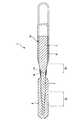
図1は、ガイドワイヤの実施形態を示す縦断面図、図2は、ガイドワイヤにおけるワイヤ本体の接合部付近を拡大して示す縦断面図である。なお、説明の都合上、図1および図2中の右側を「基端」、左側を「先端」という。また、図1および図2中では、理解を容易にするため、ガイドワイヤの長さ方向を短縮し、ガイドワイヤの太さ方向を誇張して模式的に図示しており、長さ方向と太さ方向の比率は実際とは異なる。Figure 1 isa longitudinal sectional view showing an embodiment of agas guide wire, FIG. 2is a longitudinal sectional view showing an enlarged vicinity of the joint portion of the wire body inmoth guide wire. For convenience of explanation, the right side in FIGS. 1 and 2 is referred to as “base end”, and the left side is referred to as “tip”. Further, in FIG. 1 and FIG. 2, for easy understanding, the length direction of the guide wire is shortened and the thickness direction of the guide wire is exaggerated and schematically illustrated. The vertical ratio is different from the actual one.
図1に示すガイドワイヤ1は、カテーテル(内視鏡も含む)の内腔に挿入して用いられるカテーテル用ガイドワイヤであって、先端側に配置された第1ワイヤ2と、第1ワイヤ2の基端側に配置された第2ワイヤ3とを溶接により接合(連結)してなるワイヤ本体10と、螺旋状のコイル4とを有している。ガイドワイヤ1の全長は、特に限定されないが、200〜5000mm程度であるのが好ましい。 A guide wire 1 shown in FIG. 1 is a guide wire for a catheter that is used by being inserted into the lumen of a catheter (including an endoscope), and includes a
第1ワイヤ2は、柔軟性または弾性を有する線材で構成されている。第1ワイヤ2の長さは、特に限定されないが、20〜1000mm程度であるのが好ましい。 The
本実施形態では、第1ワイヤ2は、その外径が一定である部分と、外径が先端方向へ向かって漸減しているテーパ状の部分(外径漸減部)とを有する。後者は、一箇所でも二箇所以上でもよく、図示の実施形態では、一箇所の外径漸減部15を有している。 In the present embodiment, the
このような外径漸減部15を有することにより、第1ワイヤ2の剛性(曲げ剛性、ねじり剛性)を先端方向に向かって徐々に減少させることができ、その結果、ガイドワイヤ1は、先端部に良好な柔軟性を得て、血管等への追従性、安全性が向上すると共に、折れ曲がり等も防止することができる。 By having the outer diameter gradually decreasing
外径漸減部15のテーパ角度(外径の減少率)は、ワイヤ長手方向に沿って一定でも、長手方向に沿って変化する部位があってもよい。例えば、テーパ角度(外径の減少率)が比較的大きい箇所と比較的小さい箇所とが複数回交互に繰り返して形成されているようなものでもよい。 The taper angle (decrease rate of the outer diameter) of the outer diameter gradually decreasing
第1ワイヤ2の基端側の部分(外径漸減部15より基端側の部分)は、その外径が第1ワイヤ2の基端まで一定となっている。 The portion of the
第1ワイヤ2の基端には、第2ワイヤ3の先端が例えば溶接により接続(連結)されている。第2ワイヤ3は、柔軟性または弾性を有する線材で構成されている。第2ワイヤ3の長さは、特に限定されないが、20〜4800mm程度であるのが好ましい。 The distal end of the second wire 3 is connected (coupled) to the proximal end of the
第2ワイヤ3の先端部には、その先端(第2ワイヤ3の最先端)から基端方向に向かって外径が漸増するテーパ部16が形成されている。そして、第2ワイヤ3のテーパ部16より基端側においては、その外径はワイヤ長手方向に沿ってほぼ一定である。そして、第2ワイヤ3の先端(テーパ部16の先端)の外径は、第1ワイヤ2の基端の外径と同一である。 A tapered
このように、第1ワイヤ2の平均外径が第2ワイヤ3の平均外径より小さいことにより、ガイドワイヤ1は、その先端側である第1ワイヤ2上では柔軟性に富み、基端側である第2ワイヤ3上では比較的剛性が高いものとなるので、先端部の柔軟性と優れた操作性(押し込み性、トルク伝達性等)とを両立することができる。そして、第2ワイヤ3の先端部にテーパ部16を有することにより、第2ワイヤ3から第1ワイヤ2への物理的特性、特に弾性が滑らかに変化し、両ワイヤ2、3の接合部(接合面)14の前後において優れた押し込み性やトルク伝達性が発揮され、耐キンク性も向上する。 Thus, since the average outer diameter of the
第1ワイヤ2および第2ワイヤ3の構成材料は、特に限定されず、それぞれ、例えば、ステンレス鋼(例えば、SUS304、SUS303、SUS316、SUS316L、SUS316J1、SUS316J1L、SUS405、SUS430、SUS434、SUS444、SUS429、SUS430F、SUS302等SUSの全品種)、ピアノ線、コバルト系合金などの各種金属材料を使用することができるが、そのなかでも特に、擬弾性を示す合金(超弾性合金を含む。)が好ましい。より好ましくは超弾性合金である。 The constituent materials of the
超弾性合金は、比較的柔軟であるとともに、復元性があり、曲がり癖が付き難いので、第1ワイヤ2を超弾性合金で構成することにより、ガイドワイヤ1は、その先端側の部分に十分な柔軟性と曲げに対する復元性が得られ、複雑に湾曲・屈曲する血管に対する追従性が向上し、より優れた操作性が得られるとともに、第1ワイヤ2が湾曲・屈曲変形を繰り返しても、第1ワイヤ2に備わる復元性により曲がり癖が付かないので、ガイドワイヤ1の使用中に第1ワイヤ2に曲がり癖が付くことによる操作性の低下を防止することができる。 Since the superelastic alloy is relatively flexible, has a resilience, and is difficult to bend, the guide wire 1 can be sufficiently formed at the tip side by configuring the
擬弾性合金には、引張りによる応力−ひずみ曲線のいずれの形状も含み、As、Af、Ms、Mf等の変態点が顕著に測定できるものも、できないものも含み、応力により大きく変形(歪)し、応力の除去により元の形状にほぼ戻るものは全て含まれる。 Pseudoelastic alloys include any shape of stress-strain curve due to tension, including those that can measure the transformation point of As, Af, Ms, Mf, etc., and those that cannot be measured. However, everything that returns to its original shape by removing stress is included.
超弾性合金の好ましい組成としては、49〜52原子%NiのNi−Ti合金等のNi−Ti系合金、38.5〜41.5重量%ZnのCu−Zn合金、1〜10重量%XのCu−Zn−X合金(Xは、Be、Si、Sn、Al、Gaのうちの少なくとも1種)、36〜38原子%AlのNi−Al合金等が挙げられる。このなかでも特に好ましいものは、上記のNi−Ti系合金である。なお、Ni−Ti系合金に代表される超弾性合金は、後述する樹脂被覆層8、9の密着性にも優れている。 The preferred composition of the superelastic alloy is Ni-Ti alloy such as Ni-Ti alloy of 49-52 atomic% Ni, Cu-Zn alloy of 38.5-41.5 wt% Zn, 1-10 wt% X Cu-Zn-X alloy (X is at least one of Be, Si, Sn, Al, and Ga), 36-38 atomic% Al-Ni-Al alloy, and the like. Of these, the Ni-Ti alloy is particularly preferable. In addition, the superelastic alloy represented by the Ni-Ti system alloy is excellent also in the adhesiveness of the
コバルト系合金は、ワイヤとしたときの弾性率が高く、かつ適度な弾性限度を有している。このため、コバルト系合金で構成されたワイヤは、トルク伝達性に優れ、座屈等の問題が極めて生じ難い。コバルト系合金としては、構成元素としてCoを含むものであれば、いかなるものを用いてもよいが、Coを主成分として含むもの(Co基合金:合金を構成する元素中で、Coの含有率が重量比で最も多い合金)が好ましく、Co−Ni−Cr系合金を用いるのがより好ましい。このような組成の合金を用いることにより、前述した効果がさらに顕著なものとなる。また、このような組成の合金は、弾性係数が高く、かつ高弾性限度としても冷間成形可能で、高弾性限度であることにより、座屈の発生を十分に防止しつつ、小径化することができ、所定部位に挿入するのに十分な柔軟性と剛性を備えるものとすることができる。 The cobalt-based alloy has a high elastic modulus when used as a wire and has an appropriate elastic limit. For this reason, the wire comprised by the cobalt type alloy is excellent in torque transferability, and problems, such as buckling, do not arise very much. Any cobalt-based alloy may be used as long as it contains Co as a constituent element, but it contains Co as a main component (Co-based alloy: Co content in the elements constituting the alloy) Is preferable, and a Co—Ni—Cr alloy is more preferably used. By using an alloy having such a composition, the above-described effects become more remarkable. In addition, an alloy having such a composition has a high elastic modulus and can be cold-formed even as a high elastic limit, and by reducing the diameter while sufficiently preventing buckling from occurring due to the high elastic limit. And can have sufficient flexibility and rigidity to be inserted into a predetermined portion.
Co−Ni−Cr系合金としては、例えば、28〜50wt%Co−10〜30wt%Ni−10〜30wt%Cr−残部Feの組成からなる合金や、その一部が他の元素(置換元素)で置換された合金等が好ましい。置換元素の含有は、その種類に応じた固有の効果を発揮する。例えば、置換元素として、Ti、Nb、Ta、Be、Moから選択される少なくとも1種を含むことにより、第2ワイヤ3の強度のさらなる向上等を図ることができる。なお、Co、Ni、Cr以外の元素を含む場合、その(置換元素全体の)含有量は30wt%以下であるのが好ましい。 Examples of the Co—Ni—Cr alloy include alloys having a composition of 28 to 50 wt% Co-10 to 30 wt% Ni-10 to 30 wt% Cr—remainder Fe, and a part of the other elements (substitution elements). Alloys substituted with are preferred. The inclusion of a substitution element exhibits a unique effect depending on the type. For example, the strength of the second wire 3 can be further improved by including at least one selected from Ti, Nb, Ta, Be, and Mo as the substitution element. In addition, when an element other than Co, Ni, and Cr is included, the content (of the entire substituted element) is preferably 30 wt% or less.
また、Co、Ni、Crの一部は、他の元素で置換してもよい。例えば、Niの一部をMnで置換してもよい。これにより、例えば、加工性のさらなる改善等を図ることができる。また、Crの一部をMoおよび/またはWで置換してもよい。これにより、弾性限度のさらなる改善等を図ることができる。Co−Ni−Cr系合金の中でも、Moを含む、Co−Ni−Cr−Mo系合金が特に好ましい。 Further, a part of Co, Ni, and Cr may be substituted with other elements. For example, a part of Ni may be substituted with Mn. Thereby, the further improvement of workability etc. can be aimed at, for example. Further, a part of Cr may be replaced with Mo and / or W. Thereby, the further improvement of an elastic limit, etc. can be aimed at. Among Co—Ni—Cr alloys, Co—Ni—Cr—Mo alloys containing Mo are particularly preferable.
Co−Ni−Cr系合金の具体的な組成としては、例えば、[1]40wt%Co−22wt%Ni−25wt%Cr−2wt%Mn−0.17wt%C−0.03wt%Be−残部Fe、[2]40wt%Co−15wt%Ni−20wt%Cr−2wt%Mn−7wt%Mo−0.15wt%C−0.03wt%Be−残部Fe、[3]42wt%Co−13wt%Ni−20wt%Cr−1.6wt%Mn−2wt%Mo−2.8wt%W−0.2wt%C−0.04wt%Be−残部Fe、[4]45wt%Co−21wt%Ni−18wt%Cr−1wt%Mn−4wt%Mo−1wt%Ti−0.02wt%C−0.3wt%Be−残部Fe、[5]34wt%Co−21wt%Ni−14wt%Cr−0.5wt%Mn−6wt%Mo−2.5wt%Nb−0.5wt%Ta−残部Fe等が挙げられる。本発明でいうCo−Ni−Cr系合金とはこれらの合金を包含する概念である。 As a specific composition of the Co—Ni—Cr alloy, for example, [1] 40 wt% Co-22 wt% Ni-25 wt% Cr-2 wt% Mn—0.17 wt% C-0.03 wt% Be—balance Fe [2] 40 wt% Co-15 wt% Ni-20 wt% Cr-2 wt% Mn-7 wt% Mo-0.15 wt% C-0.03 wt% Be-balance Fe, [3] 42 wt% Co-13 wt% Ni- 20 wt% Cr-1.6 wt% Mn-2 wt% Mo-2.8 wt% W-0.2 wt% C-0.04 wt% Be-balance Fe, [4] 45 wt% Co-21 wt% Ni-18 wt% Cr- 1 wt% Mn-4 wt% Mo-1 wt% Ti-0.02 wt% C-0.3 wt% Be-balance Fe, [5] 34 wt% Co-21 wt% Ni-14 wt% Cr-0.5 wt% Mn-6w % Mo-2.5wt% Nb-0.5wt% Ta- balance being Fe, and the like. The Co—Ni—Cr alloy referred to in the present invention is a concept that includes these alloys.
第1ワイヤ2と第2ワイヤ3とは、異なる材料で構成されていてもよいが、同一または同種(合金において主とする金属材料が等しい)の金属材料で構成されているのが好ましい。これにより、接合部(溶接部)14の接合強度がより高くなり、接合部14の外径が小さくても、離脱等を生じることなく、優れたトルク伝達性等を発揮する。 The
この場合、第1ワイヤ2および第2ワイヤ3は、それぞれ、前述した超弾性合金で構成されているのが好ましく、その中でもNi−Ti系合金で構成されているのがより好ましい。これにより、ワイヤ本体10のテーパ部16より先端側において優れた柔軟性を確保するとともに、ワイヤ本体10の基端側の部分では、十分な剛性(曲げ剛性、ねじり剛性)を確保することができる。その結果、ガイドワイヤ1は、優れた押し込み性やトルク伝達性を得て良好な操作性を確保しつつ、先端側においては良好な柔軟性、復元性を得て血管、胆管、膵管への追従性、安全性が向上する。 In this case, each of the
第1ワイヤ2の先端部外周には、コイル4が配置されている。このコイル4は、線材(細線)を螺旋状に巻回してなる部材であり、第1ワイヤ2の少なくとも先端側の部分を覆うように設置されている。図示の構成では、第1ワイヤ2の先端側の部分は、コイル4の内側のほぼ中心部に挿通されている。また、第1ワイヤ2の先端側の部分は、コイル4の内面と非接触で挿通されている。接合部14は、コイル4の基端より基端側に位置している。 A coil 4 is disposed on the outer periphery of the distal end portion of the
なお、図示の構成では、コイル4は、外力を付与しない状態で、螺旋状に巻回された線材同士の間にやや隙間が空いているが、図示と異なり、外力を付与しない状態で、螺旋状に巻回された線材同士が隙間なく密に配置されていてもよい。 In the configuration shown in the figure, the coil 4 has a slight gap between the spirally wound wires in a state where no external force is applied, but unlike the illustration, the coil 4 is spiraled in a state where no external force is applied. Wires wound in a shape may be densely arranged without a gap.
コイル4は、金属材料で構成されているのが好ましい。コイル4を構成する金属材料としては、例えば、ステンレス鋼、超弾性合金、コバルト系合金や、金、白金、タングステン等の貴金属またはこれらを含む合金(例えば白金−イリジウム合金)等が挙げられる。特に、貴金属のようなX線不透過材料で構成した場合には、ガイドワイヤ1にX線造影性が得られ、X線透視下で先端部の位置を確認しつつ生体内に挿入することができ、好ましい。また、コイル4は、その先端側と基端側とを異なる材料で構成してもよい。例えば、先端側をX線不透過材料のコイル、基端側をX線を比較的透過する材料(ステンレス鋼など)のコイルにて各々構成してもよい。なお、コイル4の全長は、特に限定されないが、5〜500mm程度であるのが好ましい。 The coil 4 is preferably made of a metal material. Examples of the metal material constituting the coil 4 include stainless steel, superelastic alloy, cobalt-based alloy, noble metals such as gold, platinum, tungsten, and alloys containing these (for example, platinum-iridium alloy). In particular, when the guide wire 1 is made of an X-ray opaque material such as a noble metal, X-ray contrast can be obtained in the guide wire 1, and the guide wire 1 can be inserted into the living body while confirming the position of the tip under X-ray fluoroscopy. It is possible and preferable. Further, the coil 4 may be composed of different materials on the distal end side and the proximal end side. For example, the distal end side may be constituted by a coil made of an X-ray opaque material, and the proximal end side may be constituted by a coil made of a material that relatively transmits X-rays (such as stainless steel). The total length of the coil 4 is not particularly limited, but is preferably about 5 to 500 mm.
コイル4の基端部および先端部は、それぞれ、固定材料11および12により第1ワイヤ2に固定されている。また、コイル4の中間部(先端寄りの位置)は、固定材料13により第1ワイヤ2に固定されている。固定材料11、12および13は、半田(ろう材)で構成されている。なお、固定材料11、12および13は、半田に限らず、接着剤でもよい。また、コイル4の固定方法は、固定材料によるものに限らず、例えば、溶接でもよい。また、血管等の体腔の内壁の損傷を防止するために、固定材料12の先端面は、丸みを帯びているのが好ましい。 The proximal end portion and the distal end portion of the coil 4 are fixed to the
本実施形態では、このようなコイル4が設置されていることにより、第1ワイヤ2は、コイル4に覆われて接触面積が少ないので、摺動抵抗を低減することができ、よって、ガイドワイヤ1の操作性がより向上する。 In the present embodiment, since such a coil 4 is installed, the
なお、本実施形態の場合、コイル4は、線材の横断面が円形のものを用いているが、これに限らず、線材の断面が例えば楕円形、四角形(特に長方形)等のものであってもよい。 In the case of the present embodiment, the coil 4 has a circular cross section of the wire. However, the present invention is not limited to this, and the cross section of the wire is, for example, elliptical or quadrangular (particularly rectangular). Also good.
ガイドワイヤ本体10を構成する第1ワイヤ2と第2ワイヤ3とは、溶接により接続、固定されている。これにより、簡単な方法で、第1ワイヤ2と第2ワイヤ3との接合部(溶接部)14に高い接合強度が得られ、よって、ガイドワイヤ1は、第2ワイヤ3からのねじりトルクや押し込み力が確実に第1ワイヤ2に伝達される。 The
第1ワイヤ2と第2ワイヤ3との溶接方法としては、特に限定されず、例えば、摩擦圧接、レーザを用いたスポット溶接、バットシーム溶接等の突き合わせ抵抗溶接などが挙げられるが、比較的簡単で高い接合強度が得られることから、突き合わせ抵抗溶接が特に好ましい。 The method for welding the
前述したように、第1ワイヤ2の基端の外径と第2ワイヤ3の先端(テーパ部16の先端)の外径とは同一であり、従って、両ワイヤ2、3の接合端面の形状(好ましくは円形)は一致している。従って、両ワイヤ2、3を溶接するために付き合わせた際、外径差による段差は生じない。 As described above, the outer diameter of the proximal end of the
そして、両ワイヤ2、3を溶接により接合した後、両ワイヤ2、3の接合部14の外周部に、金属被覆層6が形成される。以下、この金属被覆層6の形状について説明する。 And after joining both the
図2に示すように、接合部14の先端側は、外径がほぼ一定の第1ワイヤ2であり、接合部14の基端側は、外径が基端方向に向かって漸増する第2ワイヤ3のテーパ部16であり、金属被覆層6は、これらにまたがるように形成されている。そして、金属被覆層6は、その全部または一部が、外径が基端方向に向かって漸増するテーパ状部分61で構成されている。 As shown in FIG. 2, the distal end side of the
ここで、テーパ部16のテーパ角度(ワイヤの軸線に対する外周面の角度)をα、金属被覆層6のテーパ状部分61のテーパ角度をβとすると、α>βの関係が成り立っている(図2参照)。すなわち、金属被覆層6は、第1ワイヤ2の基端部外周面とテーパ部16の外周面との角度の差を緩和するように形成されている。 Here, when the taper angle of the taper portion 16 (angle of the outer peripheral surface with respect to the axis of the wire) is α and the taper angle of the
このような金属被覆層6を形成したことにより、接合部14の前後(先端側と基端側)における急峻な角度の変化(剛性の変化)を緩和して、溶接部14における応力集中を排除または緩和することができるとともに、第2ワイヤ3から第1ワイヤ2への物理的特性、特に剛性と弾性が滑らかに変化し、両ワイヤ2、3の接合部14の前後において優れた押し込み性やトルク伝達性が発揮され、耐キンク性も向上する。 By forming the
金属被覆層6は、両ワイヤ2、3の溶接により生じた溶融金属(溶融物)の固化物で構成されている。従って、金属被覆層6の構成材料は、第1ワイヤ2の構成金属と第2ワイヤ3の構成金属の双方を含む。特に、前述したように、第1ワイヤ2と第2ワイヤ3とが同一または同種の金属材料で構成されている場合には、金属被覆層6の構成材料もそれらと同様の金属組成となる。 The
また、金属被覆層6は、前記溶融金属の固化物に対し機械加工を施して得られたものであるのが好ましい。これにより、金属被覆層6を所望の形状や表面性状にすることができ、ガイドワイヤ1の押し込み性、トルク伝達性、耐キンク性をより向上することができる。なお、機械加工としては、例えば、研削、研磨、レーザ加工等のうちの1種または2種以上を組み合わせて行うことができる。また、機械加工に代えて、あるいは機械加工の後に、エッチング等の化学処理を施してもよい。 Moreover, it is preferable that the
金属被覆層6の平均厚さは、特に限定されないが、1〜100μm程度であるのが好ましく、1〜30μm程度であるのがより好ましい。金属被覆層6の厚さが薄すぎると、上述した金属被覆層6の機能を十分に発揮することができないおそれがあり、また厚さが厚すぎると、第1ワイヤ2、第2ワイヤ3間での物理的特性(剛性、弾性等)の移行が滑らかに変化しないおそれがある。 The average thickness of the
金属被覆層6のワイヤ長手方向の長さは、特に限定されないが、0.5〜2.0mm程度であるのが好ましく、0.5〜1.0mm程度であるのがより好ましい。 The length of the
このような金属被覆層6は、例えば次のようにして形成される。
第1ワイヤ2と第2ワイヤ3とは、例えばバット溶接機によって、所定の電圧を印加されながら第1ワイヤ2の基端と第2ワイヤ3の先端とが加圧接触される。この加圧接触により、接触部分には薄い(例えば0.01〜50μm程度)溶融層が形成され、この溶融層が冷却固化すると接合部14が形成され、第1ワイヤ2と第2ワイヤ3とが強固に接合される。この溶接の際に、接合部14を含む所定の領域(例えば、接合部14から前後0.2〜8mm程度の範囲)に外径が増大した隆起部分が形成される。この隆起部分は、第1ワイヤ2および第2ワイヤ3の溶融物が固化したものである。Such a
The
この溶融物の隆起部分を適度に除去して整形する(形状を整える)ことにより、所望形状の金属被覆層6を得る。整形方法としては、隆起部分に対し、例えば、研削、研磨、レーザ加工等の機械加工や、エッチング等の化学処理が挙げられる。機械加工を施した後、仕上げ等の目的で化学処理を施してもよい。このような整形により、金属被覆層6の外周面は、実質的に平滑な面とすることができる。 The
金属被覆層6は、第1ワイヤ2および第2ワイヤ3の溶融固化物を整形したものとして説明したが、これに限らず、溶融固化物を一部分残して凸状とし、またはほぼ取り除いた後に、その表面に別の金属被覆物を上記したように被覆して構成したものでもよい。この場合、別の金属被覆物としては、第1ワイヤ2や第2ワイヤ3と同じ種類の材料にて形成することができる。また、金属被覆層6の代わりに、プラスチックによる被覆層(樹脂被覆層)を形成してもよい。もちろん、金属被覆層6の全部または一部をプラスチック等による被覆層で被覆した構成でもよい。 Although the
金属被覆層6のテーパ状部分61は、図2に示すように、その外径が基端方向に向かって直線的に漸増しているが、テーパ状部分61は、凹面を形成していてもよく、または逆に凸面を形成していてもよい。 As shown in FIG. 2, the tapered
図1に示すように、ワイヤ本体10は、その外周面(外表面)の全部または一部を覆う樹脂被覆層8、9を有している。図示の実施形態では、第1ワイヤ2および第2ワイヤ3の外周に、それぞれ、樹脂被覆層8および9が設けられている。
これらの樹脂被覆層8、9は、種々の目的で形成することができるが、その一例として、ガイドワイヤ1の摩擦(摺動抵抗)を低減し、摺動性を向上させることによってガイドワイヤ1の操作性を向上させることがある。As shown in FIG. 1, the
Although these
また、図示と異なり、樹脂被覆層8または9が、金属被覆層6の外周を覆うように設けられていてもよい。これにより、ワイヤ本体10の外径変化(テーパ角度の変化)をさらに緩和することができ、ガイドワイヤ1の押し込み性、トルク伝達性、耐キンク性をより向上することができるとともに、ガイドワイヤ1の長手方向の移動操作性を向上することができる。 Unlike the illustration, the
ガイドワイヤ1の摩擦(摺動抵抗)の低減を図るためには、樹脂被覆層8、9は、以下に述べるような摩擦を低減し得る材料で構成されているのが好ましい。これにより、ガイドワイヤ1とともに用いられるカテーテルの内壁との摩擦抵抗(摺動抵抗)が低減されて摺動性が向上し、カテーテル内でのガイドワイヤ1の操作性がより良好なものとなる。また、ガイドワイヤ1の摺動抵抗が低くなることで、ガイドワイヤ1をカテーテル内で移動および/または回転した際に、ガイドワイヤ1のキンク(折れ曲がり)やねじれ、特に接合部14付近におけるキンクやねじれをより確実に防止することができる。 In order to reduce the friction (sliding resistance) of the guide wire 1, the
このような摩擦を低減し得る材料としては、例えば、ポリエチレン、ポリプロピレン等のポリオレフィン、ポリ塩化ビニル、ポリエステル(PET、PBT等)、ポリアミド、ポリイミド、ポリウレタン、ポリスチレン、ポリカーボネート、シリコーン樹脂、フッ素系樹脂(PTFE、ETFE等)、またはこれらの複合材料が挙げられる。 Examples of materials that can reduce such friction include polyolefins such as polyethylene and polypropylene, polyvinyl chloride, polyesters (PET, PBT, etc.), polyamides, polyimides, polyurethanes, polystyrenes, polycarbonates, silicone resins, fluorine resins ( PTFE, ETFE, etc.) or a composite material thereof.
その中でも特に、フッ素系樹脂(またはこれを含む複合材料)を用いた場合には、ガイドワイヤ1とカテーテルの内壁との摩擦抵抗(摺動抵抗)をより効果的に低減し、摺動性を向上させることができ、カテーテル内でのガイドワイヤ1の操作性がより良好なものとなる。また、これにより、ガイドワイヤ1をカテーテル内で移動および/または回転した際に、ガイドワイヤ1のキンク(折れ曲がり)やねじれ、特に溶接部付近におけるキンクやねじれをより確実に防止することができる。 In particular, when a fluorine-based resin (or a composite material containing the same) is used, the frictional resistance (sliding resistance) between the guide wire 1 and the inner wall of the catheter is more effectively reduced, and slidability is improved. This can improve the operability of the guide wire 1 in the catheter. In addition, this makes it possible to more reliably prevent kinking (bending) and twisting of the guide wire 1, particularly kinking and twisting in the vicinity of the welded portion, when the guide wire 1 is moved and / or rotated in the catheter.
また、フッ素系樹脂(またはこれを含む複合材料)を用いた場合には、焼きつけ、吹きつけ等の方法により、樹脂材料を加熱した状態で、ワイヤ本体10への被覆を行うことができる。これにより、ワイヤ本体10と、樹脂被覆層8、9との密着性は特に優れたものとなる。 In addition, when a fluororesin (or a composite material containing the same) is used, the
また、樹脂被覆層8、9がシリコーン樹脂(またはこれを含む複合材料)で構成されたものであると、樹脂被覆層8、9を形成する(ワイヤ本体10に被覆する)際に、加熱しなくても、ワイヤ本体10に確実かつ強固に密着した樹脂被覆層8、9を形成することができる。すなわち、樹脂被覆層8、9をシリコーン樹脂(またはこれを含む複合材料)で構成されたものとする場合、反応硬化型の材料等を用いることができるため、樹脂被覆層8、9の形成を室温にて行うことができる。このように、室温にて樹脂被覆層8、9を形成することにより、簡便にコーティングができるとともに、溶接部14における第1ワイヤ2と第2ワイヤ3との接合強度を十分に維持した状態にてガイドワイヤの操作ができる。 Further, when the
また、樹脂被覆層8、9(特に先端側の樹脂被覆層8)は、ガイドワイヤ1を血管等に挿入する際の安全性の向上を目的として設けることもできる。この目的のためには、樹脂被覆層8、9は柔軟性に富む材料(軟質材料、弾性材料)で構成されているのが好ましい。 Further, the resin coating layers 8 and 9 (particularly, the resin coating layer 8 on the distal end side) can be provided for the purpose of improving safety when the guide wire 1 is inserted into a blood vessel or the like. For this purpose, the
このような柔軟性に富む材料としては、例えば、ポリエチレン、ポリプロピレン等のポリオレフィン、ポリ塩化ビニル、ポリエステル(PET、PBT等)、ポリアミド、ポリイミド、ポリウレタン、ポリスチレン、シリコーン樹脂、ポリウレタンエラストマー、ポリエステルエラストマー、ポリアミドエラストマー等の熱可塑性エラストマー、ラテックスゴム、シリコーンゴム等の各種ゴム材料、またはこれらのうちに2以上を組み合わせた複合材料が挙げられる。 Examples of such flexible materials include polyolefins such as polyethylene and polypropylene, polyvinyl chloride, polyester (PET, PBT, etc.), polyamide, polyimide, polyurethane, polystyrene, silicone resin, polyurethane elastomer, polyester elastomer, polyamide. Examples thereof include thermoplastic elastomers such as elastomers, various rubber materials such as latex rubber and silicone rubber, or composite materials in which two or more thereof are combined.
特に、樹脂被覆層8、9が前述した熱可塑性エラストマーや各種ゴム材料で構成されたものである場合には、ガイドワイヤ1の先端部の柔軟性がより向上するため、血管等への挿入時に、血管内壁等を傷つけることをより確実に防止することができ、安全性が極めて高い。 In particular, when the
このような樹脂被覆層8、9は、それぞれ、2層以上の積層体でもよい。また、樹脂被覆層8と樹脂被覆層9とは、同一材料で構成されていても、異なる材料で構成されていてもよい。例えば、ガイドワイヤ1の先端側に位置する樹脂被覆層8は、前述した柔軟性に富む材料(軟質材料、弾性材料)で構成し、ガイドワイヤ1の基端側に位置する樹脂被覆層9は、前述した摩擦を低減し得る材料で構成することができる。これにより、摺動性(操作性)の向上と安全性の向上の両立を図ることができる。 Each of the
樹脂被覆層8、9の厚さは、特に限定されず、樹脂被覆層8、9の形成目的や構成材料、形成方法等を考慮して適宜されるが、通常は、樹脂被覆層8、9共に、厚さ(平均)が1〜100μm程度であるのが好ましく、1〜30μm程度であるのがより好ましい。樹脂被覆層8、9の厚さが薄すぎると、樹脂被覆層8、9の形成目的が十分に発揮されないことがあり、また、樹脂被覆層8、9の剥離が生じるおそれがある。また、樹脂被覆層8、9の厚さが厚すぎると、ワイヤ本体10の物理的特性に影響を与えるおそれがあり、また樹脂被覆層8、9の剥離が生じるおそれがある。 The thickness of the
なお、本発明では、ワイヤ本体10の外周面(表面)に、樹脂被覆層8、9の密着性を向上するための処理(粗面加工、化学処理、熱処理等)を施したり、樹脂被覆層8、9の密着性を向上し得る中間層を設けたりすることもできる。 In the present invention, the outer peripheral surface (surface) of the
ガイドワイヤ1の少なくとも先端部の外面には、親水性材料がコーティングされているのが好ましい。本実施形態では、ガイドワイヤ1の先端からテーパ部16の基端付近に至るまでの領域におけるガイドワイヤ1の外周面に、親水性材料がコーティングされている。これにより、親水性材料が湿潤して潤滑性を生じ、ガイドワイヤ1の摩擦(摺動抵抗)が低減し、摺動性が向上する。従って、ガイドワイヤ1の操作性が向上する。 It is preferable that the outer surface of at least the distal end portion of the guide wire 1 is coated with a hydrophilic material. In this embodiment, the hydrophilic material is coated on the outer peripheral surface of the guide wire 1 in the region from the distal end of the guide wire 1 to the vicinity of the proximal end of the tapered
親水性材料としては、例えば、セルロース系高分子物質、ポリエチレンオキサイド系高分子物質、無水マレイン酸系高分子物質(例えば、メチルビニルエーテル−無水マレイン酸共重合体のような無水マレイン酸共重合体)、アクリルアミド系高分子物質(例えば、ポリアクリルアミド、ポリグリシジルメタクリレート−ジメチルアクリルアミド(PGMA−DMAA)のブロック共重合体)、水溶性ナイロン、ポリビニルアルコール、ポリビニルピロリドン等が挙げられる。 Examples of hydrophilic materials include cellulose-based polymer materials, polyethylene oxide-based polymer materials, and maleic anhydride-based polymer materials (for example, maleic anhydride copolymers such as methyl vinyl ether-maleic anhydride copolymer). Acrylamide polymer substances (for example, polyacrylamide, polyglycidyl methacrylate-dimethylacrylamide (PGMA-DMAA) block copolymer), water-soluble nylon, polyvinyl alcohol, polyvinylpyrrolidone and the like.
このような親水性材料は、多くの場合、湿潤(吸水)により潤滑性を発揮し、ガイドワイヤ1とともに用いられるカテーテルの内壁との摩擦抵抗(摺動抵抗)を低減する。これにより、ガイドワイヤ1の摺動性が向上し、カテーテル内でのガイドワイヤ1の操作性がより良好なものとなる。 In many cases, such a hydrophilic material exhibits lubricity by wetting (water absorption) and reduces frictional resistance (sliding resistance) with the inner wall of the catheter used together with the guide wire 1. Thereby, the slidability of the guide wire 1 is improved, and the operability of the guide wire 1 in the catheter becomes better.
図3は、ガイドワイヤの他の実施形態を示す縦断面図である。以下、図3に示すガイドワイヤについて説明するが、図1および図2に示すガイドワイヤと同様の事項にいてはその説明を省略し、相違点を中心に説明する。また、説明の都合上、図3中の右側を「基端」、左側を「先端」という。また、図3中では、理解を容易にするため、ガイドワイヤの長さ方向を短縮し、ガイドワイヤの太さ方向を誇張して模式的に図示しており、長さ方向と太さ方向の比率は実際とは異なる。Figure 3is a longitudinal sectional view showing another embodiment of agas guide wire. Hereinafter, the guide wire shown in FIG. 3 will be described, but the description of the same matters as those of the guide wire shown in FIG. 1 and FIG. 2 will be omitted, and differences will be mainly described. For convenience of explanation, the right side in FIG. 3 is referred to as “base end”, and the left side is referred to as “tip”. Further, in FIG. 3, for ease of understanding, the length direction of the guide wire is shortened and the thickness direction of the guide wire is exaggerated and schematically illustrated. The ratio is different from the actual.
図3に示すガイドワイヤ1は、コイル4を有さない以外は、図1および図2に示すガイドワイヤ1と同様である。すなわち、図3に示すガイドワイヤ1は、先端側に配置された第1ワイヤ2と、第1ワイヤ2の基端側に配置された第2ワイヤ3とを溶接により接合(連結)してなるワイヤ本体10を有し、第1ワイヤ2と第2ワイヤ3との接合部14の外周部は、金属被覆層6により覆われている。 The guide wire 1 shown in FIG. 3 is the same as the guide wire 1 shown in FIGS. 1 and 2 except that the coil 4 is not provided. That is, the guide wire 1 shown in FIG. 3 is formed by joining (connecting) the
ワイヤ本体10の先端側の部分(第1ワイヤ2の外周面)および基端側の部分(第2ワイヤ3の外周面)は、それぞれ、樹脂被覆層8および9により被覆されている。 A portion on the distal end side (the outer peripheral surface of the first wire 2) and a portion on the proximal end side (the outer peripheral surface of the second wire 3) of the
樹脂被覆層8、9の形成目的や構成材料等については、前記と同様である。本実施形態では、特に、ガイドワイヤ1の先端側に位置する樹脂被覆層8を、前述した柔軟性に富む材料(軟質材料、弾性材料)で構成し、ガイドワイヤ1の基端側に位置する樹脂被覆層9を、前述した摩擦を低減し得る材料で構成するのが好ましい。これにより、摺動性(操作性)の向上と安全性の向上の両立を図ることができからである。この場合の具体例としては、樹脂被覆層8をポリウレタンで構成し、樹脂被覆層9をフッ素系樹脂(PTFE、ETFE等)で構成する場合が挙げられる。 The purpose of forming the
また、樹脂被覆層8は、第1ワイヤ2の先端を露出することなく覆っており、しかも、樹脂被覆層8の先端は、丸みを帯びた形状であるのが好ましい。これにより、ガイドワイヤ1を血管等の体腔に挿入する際、その内壁の損傷をより有効に防止し、安全性を高めることができる。 Moreover, the resin coating layer 8 covers the
樹脂被覆層8中には、造影性を有する材料(前記X線不透過材料等)によるフィラー(粒子)が分散され、これにより造影部を構成するようにしてもよい。 In the resin coating layer 8, fillers (particles) made of a contrasting material (such as the X-ray opaque material) may be dispersed, thereby forming a contrast portion.
また、ガイドワイヤ1の少なくとも先端部の外面には、親水性材料がコーティングされているのが好ましい。本実施形態では、ガイドワイヤ1の先端からテーパ部16の基端付近に至るまでの領域におけるガイドワイヤ1の外周面に、親水性材料がコーティングされている。これにより、親水性材料が湿潤して潤滑性を生じ、ガイドワイヤ1の摩擦(摺動抵抗)が低減し、摺動性が向上する。従って、ガイドワイヤ1の操作性が向上する。 Further, it is preferable that a hydrophilic material is coated on at least the outer surface of the guide wire 1. In this embodiment, the hydrophilic material is coated on the outer peripheral surface of the guide wire 1 in the region from the distal end of the guide wire 1 to the vicinity of the proximal end of the tapered
また、親水性材料は、樹脂被覆層8の外表面の一部または外表面の全面のみに形成されていてもよい。なお、親水性材料の具体例については、前記と同様である。 Further, the hydrophilic material may be formed on a part of the outer surface of the resin coating layer 8 or only on the entire outer surface. Specific examples of the hydrophilic material are the same as described above.
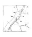
図4および図5は、それぞれ、ガイドワイヤ1をPTCA術に用いた場合における使用状態を示す図である。4 and 5are diagrams showing a use state in the case of using thegas guide wire 1 to PTCA surgery.
図4および図5中、符号40は大動脈弓、符号50は心臓の右冠状動脈、符号60は右冠状動脈開口部、符号70は血管狭窄部(病変部)である。また、符号30は大腿動脈からガイドワイヤ1を確実に右冠状動脈に導くためのガイディングカテーテル、符号20はその先端部分に拡張・収縮自在なバルーン201を有する狭窄部拡張用のバルーンカテーテルである。以下の操作は、X線透視下で行われる。 4 and 5,
図4に示すように、ガイドワイヤ1の先端をガイディングカテーテル30の先端から突出させ、右冠状動脈開口部60から右冠状動脈50内に挿入する。さらに、ガイドワイヤ1を進め、先端から右冠状動脈50内に挿入し、先端が血管狭窄部70を超えた位置で停止する。これにより、バルーンカテーテル20の通路が確保される。なお、このとき、ガイドワイヤ1の接合部14(金属被覆層6)は、大動脈弓40の下行大動脈側(生体内)に位置している。 As shown in FIG. 4, the distal end of the guide wire 1 is projected from the distal end of the guiding
次に、図5に示すように、ガイドワイヤ1の基端側から挿通されたバルーンカテーテル20の先端をガイディングカテーテル30の先端から突出させ、さらにガイドワイヤ1に沿って進め、右冠状動脈開口部60から右冠状動脈50内に挿入し、バルーン201が血管狭窄部70の位置に到達したところで停止する。 Next, as shown in FIG. 5, the distal end of the
次に、バルーンカテーテル20の基端側からバルーン拡張用の流体を注入して、バルーン201を拡張させ、血管狭窄部70を拡張する。このようにすることによって、血管狭窄部70の血管に付着堆積しているコレステロール等の堆積物は物理的に押し広げられ、血流阻害が解消できる。 Next, a balloon expansion fluid is injected from the proximal end side of the
以上、本発明のガイドワイヤの製造方法およびこの製造方法によって製造されたガイドワイヤを図示の実施形態に基づいて説明したが、本発明は、これに限定されるものではなく、ガイドワイヤを構成する各部は、同様の機能を発揮し得る任意の構成のものと置換することができる。また、任意の構成物が付加されていてもよい。Theguide wire manufacturing method of the present invention and theguide wire manufactured by this manufacturing method have been described based on the illustrated embodiment. However, the present invention is not limited to this and constitutes a guide wire. Each part can be replaced with any component that can exhibit the same function. Moreover, arbitrary components may be added.
また、本発明のガイドワイヤの製造方法によって製造されたガイドワイヤの用途は、上述したPTCA術において使用される場合に限られず、例えば血管造影や経内視鏡手技などに使用される。The use of theguide wire manufactured by theguide wire manufacturing method of the present invention is not limited to the use in the above-described PTCA operation, and is used for, for example, angiography and transendoscopy.
1 ガイドワイヤ
10 ワイヤ本体
2 第1ワイヤ
3 第2ワイヤ
4 コイル
6 金属被覆層
61 テーパ状部分
8、9 樹脂被覆層
11、12、13 固定材料
14 接合部(溶接部)
15 外径漸減部
16 テーパ部
20 バルーンカテーテル
201 バルーン
30 ガイディングカテーテル
40 大動脈弓
50 右冠状動脈
60 右冠状動脈開口部
70 血管狭窄部
DESCRIPTION OF SYMBOLS 1
15 gradually decreasing
Claims (5)
Translated fromJapanese前記第1工程の前記第1ワイヤと前記第2ワイヤとの溶接により生じた溶融金属の固化物の一部を除去して整形することにより、前記第1ワイヤと前記第2ワイヤの接合面の外周部に、前記第1ワイヤの基端部外周面と前記テーパ部の外周面との角度の差を緩和する金属被覆層を形成する第2工程とを有することを特徴とするガイドワイヤの製造方法。 By removing and shaping a part of the solidified product of the molten metal generated by welding the first wire and the second wire in the first step, the bonding surface of the first wire and the second wire A guide wire manufacturing method comprising: a second step of forming a metal coating layer on the outer peripheral portion for reducing an angle difference between the outer peripheral surface of the proximal end portion of the first wire and the outer peripheral surface of the tapered portion. Method.
前記第1工程の前記第1ワイヤと前記第2ワイヤとの溶接により生じた溶融金属の固化物の一部を除去して整形することにより、前記第1ワイヤと前記第2ワイヤの接合面の外周部に、その外径が基端方向に向かって漸増するテーパ状部分を有し、かつ当該テーパ状部分のテーパ角度が前記テーパ部のテーパ角度より小さい金属被覆層を形成する第2工程とを有することを特徴とするガイドワイヤの製造方法。 By removing and shaping a part of the solidified product of the molten metal generated by welding the first wire and the second wire in the first step, the bonding surface of the first wire and the second wire A second step of forming, on the outer peripheral portion, a metal covering layer having a tapered portion whose outer diameter gradually increases in the proximal direction and a taper angle of the tapered portion smaller than the taper angle of the tapered portion; A method of manufacturing a guide wire, comprising:
Priority Applications (6)
| Application Number | Priority Date | Filing Date | Title |
|---|---|---|---|
| JP2005118613AJP4734015B2 (en) | 2005-04-15 | 2005-04-15 | Guide wire manufacturing method |
| DE602006014047TDE602006014047D1 (en) | 2005-04-15 | 2006-04-11 | guidewire |
| CN2006100724028ACN1846803B (en) | 2005-04-15 | 2006-04-11 | Guide wire |
| AT06112479TATE466620T1 (en) | 2005-04-15 | 2006-04-11 | GUIDE WIRE |
| EP06112479AEP1712251B1 (en) | 2005-04-15 | 2006-04-11 | Guide Wire |
| US11/402,796US20060235336A1 (en) | 2005-04-15 | 2006-04-13 | Guide wire |
Applications Claiming Priority (1)
| Application Number | Priority Date | Filing Date | Title |
|---|---|---|---|
| JP2005118613AJP4734015B2 (en) | 2005-04-15 | 2005-04-15 | Guide wire manufacturing method |
Publications (2)
| Publication Number | Publication Date |
|---|---|
| JP2006296478A JP2006296478A (en) | 2006-11-02 |
| JP4734015B2true JP4734015B2 (en) | 2011-07-27 |
Family
ID=37076681
Family Applications (1)
| Application Number | Title | Priority Date | Filing Date |
|---|---|---|---|
| JP2005118613AExpired - Fee RelatedJP4734015B2 (en) | 2005-04-15 | 2005-04-15 | Guide wire manufacturing method |
Country Status (2)
| Country | Link |
|---|---|
| JP (1) | JP4734015B2 (en) |
| CN (1) | CN1846803B (en) |
Families Citing this family (11)
| Publication number | Priority date | Publication date | Assignee | Title |
|---|---|---|---|---|
| NZ585523A (en)* | 2007-11-21 | 2014-03-28 | Becton Dickinson Co | Safety stylet |
| JP5806441B2 (en)* | 2008-08-07 | 2015-11-10 | テルモ株式会社 | Guide wire |
| WO2010044473A1 (en)* | 2008-10-17 | 2010-04-22 | 日本軽金属株式会社 | Joining quality management method and joining quality management apparatus |
| EP2554210B1 (en)* | 2010-03-26 | 2019-01-16 | Terumo Kabushiki Kaisha | Guide wire |
| CN102106715B (en)* | 2010-11-09 | 2012-11-28 | 麻树人 | Endoscope guide wire |
| US9636485B2 (en) | 2013-01-17 | 2017-05-02 | Abbott Cardiovascular Systems, Inc. | Methods for counteracting rebounding effects during solid state resistance welding of dissimilar materials |
| JP5718421B2 (en)* | 2013-08-15 | 2015-05-13 | テルモ株式会社 | Guide wire |
| US10071229B2 (en) | 2015-04-14 | 2018-09-11 | Abbott Cardiovascular Systems, Inc. | Mechanisms for improving the stiffness transition across a dissimilar metal weld joint |
| CN111405923A (en)* | 2018-02-01 | 2020-07-10 | 朝日英达科株式会社 | Guide wire |
| JP7557528B2 (en)* | 2020-03-30 | 2024-09-27 | テルモ株式会社 | Guidewires |
| JP2023180260A (en)* | 2020-11-12 | 2023-12-21 | テルモ株式会社 | guide wire |
Family Cites Families (5)
| Publication number | Priority date | Publication date | Assignee | Title |
|---|---|---|---|---|
| US5827201A (en)* | 1996-07-26 | 1998-10-27 | Target Therapeutics, Inc. | Micro-braided guidewire |
| JP4138583B2 (en)* | 2002-08-08 | 2008-08-27 | テルモ株式会社 | Guide wire |
| JP4203358B2 (en)* | 2002-08-08 | 2008-12-24 | テルモ株式会社 | Guide wire |
| US7722551B2 (en)* | 2002-08-09 | 2010-05-25 | Terumo Kabushiki Kaisha | Guide wire |
| JP4138582B2 (en)* | 2002-08-23 | 2008-08-27 | テルモ株式会社 | Guide wire |
- 2005
- 2005-04-15JPJP2005118613Apatent/JP4734015B2/ennot_activeExpired - Fee Related
- 2006
- 2006-04-11CNCN2006100724028Apatent/CN1846803B/ennot_activeExpired - Fee Related
Also Published As
| Publication number | Publication date |
|---|---|
| CN1846803B (en) | 2010-11-10 |
| CN1846803A (en) | 2006-10-18 |
| JP2006296478A (en) | 2006-11-02 |
Similar Documents
| Publication | Publication Date | Title |
|---|---|---|
| JP4203358B2 (en) | Guide wire | |
| JP4138582B2 (en) | Guide wire | |
| JP4138583B2 (en) | Guide wire | |
| JP6759069B2 (en) | Guide wire | |
| JP4980605B2 (en) | Guide wire | |
| JP4734015B2 (en) | Guide wire manufacturing method | |
| JP2005270466A (en) | Guide wire | |
| JP2018079246A (en) | Guide wire | |
| JP4376048B2 (en) | Guide wire | |
| JP4783343B2 (en) | Guide wire | |
| JP4375951B2 (en) | Guide wire | |
| JP4734029B2 (en) | Guide wire manufacturing method | |
| JP5328835B2 (en) | Guide wire manufacturing method | |
| JP4405252B2 (en) | Medical wire | |
| JP4447597B2 (en) | Guide wire | |
| JP5073713B2 (en) | Guide wire | |
| JP4138467B2 (en) | Guide wire | |
| JP4376078B2 (en) | Guide wire | |
| JP5019868B2 (en) | Guide wire | |
| JP4455808B2 (en) | Guide wire | |
| JP5296143B2 (en) | Guide wire | |
| JP4376073B2 (en) | Guide wire | |
| JP5135452B2 (en) | Guide wire | |
| JP4783344B2 (en) | Guide wire | |
| JP2004130087A (en) | Guide wire |
Legal Events
| Date | Code | Title | Description |
|---|---|---|---|
| A621 | Written request for application examination | Free format text:JAPANESE INTERMEDIATE CODE: A621 Effective date:20080404 | |
| A977 | Report on retrieval | Free format text:JAPANESE INTERMEDIATE CODE: A971007 Effective date:20100812 | |
| A131 | Notification of reasons for refusal | Free format text:JAPANESE INTERMEDIATE CODE: A131 Effective date:20100817 | |
| A521 | Request for written amendment filed | Free format text:JAPANESE INTERMEDIATE CODE: A523 Effective date:20101015 | |
| TRDD | Decision of grant or rejection written | ||
| A01 | Written decision to grant a patent or to grant a registration (utility model) | Free format text:JAPANESE INTERMEDIATE CODE: A01 Effective date:20110412 | |
| A01 | Written decision to grant a patent or to grant a registration (utility model) | Free format text:JAPANESE INTERMEDIATE CODE: A01 | |
| A61 | First payment of annual fees (during grant procedure) | Free format text:JAPANESE INTERMEDIATE CODE: A61 Effective date:20110425 | |
| FPAY | Renewal fee payment (event date is renewal date of database) | Free format text:PAYMENT UNTIL: 20140428 Year of fee payment:3 | |
| R150 | Certificate of patent or registration of utility model | Ref document number:4734015 Country of ref document:JP Free format text:JAPANESE INTERMEDIATE CODE: R150 Free format text:JAPANESE INTERMEDIATE CODE: R150 | |
| R250 | Receipt of annual fees | Free format text:JAPANESE INTERMEDIATE CODE: R250 | |
| R250 | Receipt of annual fees | Free format text:JAPANESE INTERMEDIATE CODE: R250 | |
| R250 | Receipt of annual fees | Free format text:JAPANESE INTERMEDIATE CODE: R250 | |
| R250 | Receipt of annual fees | Free format text:JAPANESE INTERMEDIATE CODE: R250 | |
| R250 | Receipt of annual fees | Free format text:JAPANESE INTERMEDIATE CODE: R250 | |
| LAPS | Cancellation because of no payment of annual fees |