JP4732960B2 - Gradient liquid feeding method and apparatus - Google Patents
Gradient liquid feeding method and apparatusDownload PDFInfo
- Publication number
- JP4732960B2 JP4732960B2JP2006159068AJP2006159068AJP4732960B2JP 4732960 B2JP4732960 B2JP 4732960B2JP 2006159068 AJP2006159068 AJP 2006159068AJP 2006159068 AJP2006159068 AJP 2006159068AJP 4732960 B2JP4732960 B2JP 4732960B2
- Authority
- JP
- Japan
- Prior art keywords
- valve
- solution
- gradient
- pump unit
- flow path
- Prior art date
- Legal status (The legal status is an assumption and is not a legal conclusion. Google has not performed a legal analysis and makes no representation as to the accuracy of the status listed.)
- Expired - Fee Related
Links
Images

Landscapes
- Treatment Of Liquids With Adsorbents In General (AREA)
Description
Translated fromJapanese本発明は、グラジェント送液方法及び装置に関し、特に低圧グラジェント送液方法及び装置に関する。 The present invention relates to a gradient liquid feeding method and apparatus, and more particularly, to a low pressure gradient liquid feeding method and apparatus.
液体クロマトグラフィーに於いて、分析時間の短縮や分離の改善、ピーク形状の改善のために移動相の組成を変化させながら、試料成分を分離、溶出させるグラジェント溶離法を用いている。
又、グラジェント作成方法には、低圧混合方式(低圧グラジェント)と高圧混合方式(高圧グラジェント)がある。In liquid chromatography, a gradient elution method is used in which sample components are separated and eluted while changing the composition of the mobile phase in order to shorten analysis time, improve separation, and improve peak shape.
In addition, the gradient preparation method includes a low pressure mixing method (low pressure gradient) and a high pressure mixing method (high pressure gradient).
低圧グラジェントは、電磁弁などを用いて溶液の混合比率を変化させながら、ポンプの入口側で溶液を混合して、後にカラムに送り出す方法である。
一方、高圧グラジェントは、2つ以上のポンプを用いて、夫々のポンプにて溶液を送液し、その流量を調節し、ポンプの出口側で溶液を混合し、送液する方法である。The low pressure gradient is a method in which the solution is mixed on the inlet side of the pump while changing the mixing ratio of the solution using a solenoid valve or the like and then sent to the column.
On the other hand, the high-pressure gradient is a method in which two or more pumps are used to send a solution with each pump, the flow rate is adjusted, the solution is mixed on the outlet side of the pump, and the solution is sent.
従来のシングルシリンジ送液ポンプシステムに於いては、吸入と吐出を交互に繰り返す必要がある。吸入行程では、送液が行われないため送液量に脈動を来すのが通例である。この脈動を防ぐためダブルシリンジ方式がとられ、脈動のない安定した送液が行われるが、ポンプ流路切り換えバルブの設置により装置の大型化、複雑化を来し、コスト高になる問題がある。
この点を解決するために、特開2003−107065記載の発明に於いて、二台のポンプ1,2を備え、一のバルブを用いてポンプ1が送液先流路に接続され、ポンプ2が供給源流路に接続される第一状態、逆にポンプ1が供給源流路に接続され、ポンプ2が送液先流路に接続される第ニ状態、ポンプ1,2共に送液先流路に接続された第三の状態とを切り換えるバルブ3を備え、このバルブ3をポンプ1,2の吸入、吐出動作に同期して切り換える装置が提案されている。(特許文献1)In the conventional single syringe liquid feed pump system, it is necessary to alternately repeat suction and discharge. In the inhalation stroke, since the liquid feeding is not performed, it is usual that the liquid feeding amount pulsates. In order to prevent this pulsation, the double syringe system is adopted, and stable liquid feeding without pulsation is performed. However, the installation of the pump flow path switching valve increases the size and complexity of the device, which increases the cost. .
In order to solve this point, in the invention described in Japanese Patent Laid-Open No. 2003-107065, two
この構成は、ポンプシリンダ内の全容積が一度に加圧されて、送液先流路(所謂システム系)に流される。この構成は、このポンプシリンダの作動が始動、停止モード、即ち断続的であり、所謂遷移的作用が生じることが避けられない。近時使用される毛管カラムを使用する液体クロマトグラフィーに於いては、従来のクロマトグラフィーに於いては、無視しても良いような微細なる流量の変化であっても、極めて大きな乱れとなって了う。従来技術では、毛管カラムを使用する連続した流量変化のない流体流を求められる技術に対遮することは困難である。 In this configuration, the entire volume in the pump cylinder is pressurized at a time and flows into the liquid supply destination flow path (so-called system system). In this configuration, the operation of the pump cylinder is in the start / stop mode, that is, intermittent, and it is inevitable that a so-called transitional action occurs. In liquid chromatography using a capillary column that has been used recently, even a minute change in flow rate that can be ignored in conventional chromatography is extremely disturbing. End. In the prior art, it is difficult to counteract the technology that requires a fluid flow without a continuous flow rate change using a capillary column.
この従来の送液溶液を大気圧から分析システム圧力にまで圧縮する結果としての所謂遷移過程中の容積変動が生ずるのを避けるために、分析システム系に対する圧力変動又は流量変動が発生しないように、HPLCポンプ作動の溶液圧縮段階と溶液送給段階を完全に隔離する方法として、特許第3491948号(特許文献2)が提案されている。 In order to avoid volume fluctuations during the so-called transition process as a result of compressing this conventional solution from atmospheric pressure to analysis system pressure, pressure fluctuations or flow fluctuations to the analysis system system do not occur. Japanese Patent No. 3491948 (Patent Document 2) has been proposed as a method of completely isolating the solution compression stage and the solution delivery stage of the HPLC pump operation.
この発明は、第1,第2シリンジ手段と夫々に設けた駆動手段は各シリンジ手段に各々を独立に作動させるように連結される。第1,第2シリンジ手段は流体導管によって接続され、少なくとも一方が流体を送給するように受け取り、システム系に流体連通させてある。又、弁手段は第1シリンジ手段を隔絶するため前記導管に設けている。 In this invention, the first and second syringe means and the driving means provided respectively are connected to each syringe means so as to operate each independently. The first and second syringe means are connected by a fluid conduit, at least one receiving and delivering fluid to be in fluid communication with the system system. A valve means is provided in the conduit for isolating the first syringe means.
又、第1,第2シリンジには夫々の内部圧力を測定する圧力検出手段を設けている。第1,第2シリンジ手段及び弁手段の作動を制御する制御手段を設け、この制御手段は第1,第2圧力検出手段の各出力を受け、第1シリンジが隔絶されている際には、第1シリンジ内に第2圧力検出手段によって測定された受け取りシステム内の圧力を表す第2シリンジ内の圧力に等しい圧力が充填された後に、弁手段を作動させて、第1シリンジを受け取りシステムへ連通させ、実質的に一定の流量を該受け取りシステムへ送給するポンプ送り装置である。 The first and second syringes are provided with pressure detection means for measuring the internal pressures. Control means for controlling the operation of the first and second syringe means and the valve means are provided, the control means receives the outputs of the first and second pressure detection means, and when the first syringe is isolated, After the first syringe is filled with a pressure equal to the pressure in the second syringe representing the pressure in the receiving system measured by the second pressure detecting means, the valve means is activated to receive the first syringe into the receiving system. A pumping device that communicates and delivers a substantially constant flow rate to the receiving system.
この発明によれば、ポンプ作動の溶液圧縮段階とポンプ作動の溶液送給段階を完全に隔離するので、溶液が大気圧からシステム圧力(系統圧力)にまで圧縮され、その結果、受け取りシステム、クロマトグラフィーシステムに圧力変動又は流動変動が生じない。
又、クロマトグラフィーシステムへのオフライン状態からオンライン状態での溶液送給段階への遷移過程中の容積変動を回避できる等の効果を有するとされている。
しかし、該発明に於いては、第1シリンジには第1圧力測定手段、第2シリンジには第2圧力測定手段と夫々のユニットに圧力センサー及び弁手段を持つ構成であり、夫々のユニット構成が複雑となり且、又その制御も複雑となり、設備も大型化し、製造コストも高額化する結果となっている。According to the invention, the pumped solution compression stage and the pumped solution delivery stage are completely isolated, so that the solution is compressed from atmospheric pressure to the system pressure (system pressure), resulting in a receiving system, chromatogram. There are no pressure or flow fluctuations in the graphic system.
Further, it is said that it has an effect of avoiding volume fluctuations during the transition process from the offline state to the chromatography system to the solution feeding stage in the online state.
However, in the present invention, the first syringe has the first pressure measuring means, the second syringe has the second pressure measuring means, and each unit has a pressure sensor and a valve means. As a result, the control is complicated, the equipment is enlarged, and the manufacturing cost is increased.
又、最も問題となるのは圧力測定手段、即ち圧力センサーを2個使用する場合、その精度が問題である。何故なら、圧力センサーは個体差が存在するので、同一圧力条件でも異なる出力レベルを示す。高速液体クロマトグラフィーに使われている圧力センサーのレンジは0〜500MPaが多く、また0〜100MPaのものもある。圧力センサーの校正により、ある程度で圧力センサーの個体差を小さくすることが出来るが、広いレンジにわたって個体差をなくすことが出来ない。従って、特許文献2に示した発明のように、個々のポンプユニットに夫々の圧力センサーを設けて、各自の圧力センサーに出力された圧力値に基づいて圧縮工程が制御される場合、各自の圧力センサーに基づいて、各ポンプユニットの内部圧力とシステム圧力との差がそれぞれ異なる場合があり、安定した圧力で連続送液が不可能となる。 Further, the most serious problem is the accuracy when two pressure measuring means, that is, two pressure sensors are used. This is because there are individual differences in the pressure sensor, and thus output levels differ even under the same pressure condition. The range of pressure sensors used in high performance liquid chromatography is often 0 to 500 MPa, and there is also a range of 0 to 100 MPa. Pressure sensor calibration can reduce individual differences in pressure sensors to some extent, but individual differences cannot be eliminated over a wide range. Therefore, as in the invention shown in
該特許文献2に於いて、制御装置49が主シリンダー3aの圧力センサー23aとアキュムレーターの圧力センサー23bからの出力を比較して、両圧力センサーの相互校正を実施できるとしている。しかし、この状態はその明細書で述べているように、この流体連通は何れか一方の主シリンダーの送給準備完了の状態「0」、即ちピストン速度0の時に起こるもので、他のピストン速度は「正」であり、アンバランスの状態の下での測定となり、正確な値は得られず、正確な校正は出来ない。 In
又、特許文献2と同様に2個のシリンジと2個のバルブ使用し、更に2個のトランジューサーにより、二つのシリンジと共にクロマトグラフィーシステムに同時送液し、圧力の平衡化および圧力センサーの校正可能なシステムが提案されている(特許文献3)。
しかし、このシステムもセンサーとしてのトランスジューサー23,24は、共にシリンジ12とシリンジ14のそれぞれの圧力を感知するものであり、特許文献2の発明と同様にセンサー間の個体差の影響を受けて了うことは避けられない。又、バルブは図上ではロータリーバルブ16と18であるが、実施にはスイッチングバルブ20及びON/OFFバルブ21も必要となり、連続送液のためには4個のバルブが必要となり、構造も複雑となる。
更に、センサーの校正についてふれている処もあるも、送液予備加圧の配管経路は、ポンプからバルブ18内を通った後、システム26もしくは連通されていないバルブ16のポート42に行くのに対し、校正の場合(FIG4)では、バルブ18とバルブ16の両方を通過した後、合流しシステム26に向かうため配管経路が異なり、配管の圧力損失の分だけ差が生じ、正確な比較校正はできない等の問題がある。Also, as in
However, in this system, the transducers 23 and 24 as sensors both detect the pressures of the
In addition, although there are some references to sensor calibration, the pre-pressurization piping path goes from the pump through the valve 18 to the system 26 or the port 42 of the
又、電磁弁を用いたポンプの入口側で、溶媒の混合比率を変化させながら、送液する方法は特開2004−271409、特開2005−351717に記載されている(特許文献4,5)。
しかし、この発明は、2つのポンプを用い、2つのループに一時的に保留した溶液を第一のポンプによって混合溶媒を第1ループに送りながら、第2ポンプによって第2ループの溶媒を送る工程と、第1ポンプから第2ループに送りながら、第2ポンプによって第1ループの溶液を試料導入部側へ押し出す状態を交互に繰り返すようにしたものであり、切換えバルブのポンプ側の圧力測定をし、両ポンプ圧力の均衡を図らんとするものであり、切換えバルブのポンプ側と外側の分析カラムや検出器側の圧力比較は無視されており、依然として前記送給段階への遷移過程中の容積変動をクリアー出来るものではない。Also, methods for feeding liquid while changing the mixing ratio of the solvent on the inlet side of the pump using a solenoid valve are described in Japanese Patent Application Laid-Open Nos. 2004-271409 and 2005-351717 (
However, the present invention uses two pumps to send the second loop solvent by the second pump while the solution temporarily held in the two loops is sent to the first loop by the first pump. And the state in which the solution of the first loop is pushed out by the second pump to the sample introduction part while being sent from the first pump to the second loop, and the pressure on the pump side of the switching valve is measured. However, the balance between the pressures of the two pumps is intended to be balanced, and the pressure comparison between the pump side of the switching valve and the analytical column and detector side of the detector is ignored, and the pump is still in the process of transition to the feeding stage. The volume fluctuation cannot be cleared.
クロマトグラフィー分離、就中毛管カラムを使用するようなナノ、ミクロの極めて微小流量の送液を正確に確実に行なうことが出来ると共に、その構成手段が簡便であり、コストが廉価に行なえる送液手段が必要とされ、更には二つの送液機構を使用する場合の送液機構間の圧力調整を極めて正確に行うことが出来、尚且つ、より簡単な機構にてそれを達成することが求められている。
又、微小流量の送液機構に於いては、精密さに重点を置くために少量の送液にこだわり、量的に多量な送液に適さない構成になることが指摘されている。
又、試料を導入する際に、サンプルバンドの拡散による影響を避けて安定した導入を図れることが求められている。Chromatographic separation, especially nano- and micro-flows such as those using capillary columns can be performed accurately and reliably, and the means of construction is simple and the cost is low. It is required to adjust the pressure between the liquid feeding mechanisms when using two liquid feeding mechanisms, and to achieve this with a simpler mechanism. It has been.
In addition, it has been pointed out that in a minute flow rate liquid feeding mechanism, a small amount of liquid feeding is emphasized in order to focus on precision, and the configuration is not suitable for a large amount of liquid feeding.
In addition, when introducing a sample, it is required that stable introduction can be achieved while avoiding the influence of diffusion of the sample band.
低圧グラジェント法に於いて、特定の時間毎の送液に伴う段階的な溶液の組成および容量の変化しか出来ず、直線的なグラジェントを得ることが求められている。 In the low-pressure gradient method, only a stepwise change in the composition and volume of the solution accompanying liquid feeding at a specific time can be made, and it is required to obtain a linear gradient.
本発明は、低圧グラジェント法に於いて、溶液の段階状の組成の変化を極めて小さく出来るようにし、同一溶液を送液する時間(ステップ保持時間)を極めて短く出来るようにし、リニアグラジェントのような直線的なグラジェントに近づける方法および装置を得る事を目的とする。 In the low-pressure gradient method, the present invention makes it possible to make the change in the stepwise composition of the solution extremely small, and to make the time for feeding the same solution (step holding time) extremely short. An object of the present invention is to obtain a method and an apparatus for approaching such a linear gradient.
本発明は、2つ以上のポンプユニットに於いて、ポンプ内の溶液を圧縮する際に、同一圧力センサーから夫々のポンプチャンバーの内部圧力値を得ることができ、従って、同一圧力センサーに基づいて、制御部が各ポンプユニットの内部圧力を制御するので、吐き出し始めの内部圧力とシステム圧力との差が異なることが無くなり、安定した圧力でグラジェント連続送液することが出来ることを目的とする。
又、本発明は、クロマトグラフィーシステム圧力をモニタリングするシステム圧力センサーと複数のユニットの内部圧力を観測する内部圧力センサーとは、所定の流量では圧力損失がほぼ無い流路を形成させて、実際に使用されるクロマトグラフィーシステムの分離・分析条件に対応できるように圧力センサー間の誤差を校正する装置を得ることを目的とする。The present invention can obtain the internal pressure value of each pump chamber from the same pressure sensor when compressing the solution in the pump in two or more pump units, and therefore based on the same pressure sensor. Since the control unit controls the internal pressure of each pump unit, the difference between the internal pressure at the beginning of discharge and the system pressure is not different, and the purpose is to enable continuous continuous liquid feeding at a stable pressure. .
Further, the present invention provides a system pressure sensor for monitoring the chromatography system pressure and an internal pressure sensor for observing the internal pressures of a plurality of units. It is an object of the present invention to obtain an apparatus for calibrating an error between pressure sensors so as to correspond to separation / analysis conditions of a chromatography system to be used.
本発明の目的は、上記の目的を達成するため複数の送液手段を用いて正確な、且円滑な送液を行なうために、ポンプ作動の溶液圧縮段階とポンプ作動の溶液送給段階とを隔離する構成をとりながら、送液手段たる各ポンプに圧力測定手段を設けるのでなく、ポンプ作動の送給段階とポンプ作動の溶液圧縮段階の隔離を行なうものである。そのために送給段階で一つ、圧縮段階で一つの圧力測定を行ない、圧縮段階での複数の圧力測定による誤差の発生を防ぎ、送給段階と圧縮段階の隔離が行なわれ、尚且つ、送給段階と圧縮段階の接続が円滑、且確実に行なわれ、このため各送液手段は、弁手段を介して接続することにより、一つの圧力測定により圧縮段階での圧力を測定し、且送液段階に於いては送液されるクロマトグラフィーシステムの圧力と圧縮段階の圧力を制御した事により、グラジェント送液の極めて円滑な送液することが出来ることを目的とする。 An object of the present invention is to provide a solution compression stage of pump operation and a solution supply stage of pump operation in order to perform accurate and smooth liquid supply using a plurality of liquid supply means to achieve the above object. Instead of providing a pressure measuring means for each pump as a liquid feeding means while adopting an isolating configuration, the pump feeding operation stage and the pump working solution compression stage are separated. For this purpose, one pressure measurement is performed at the feeding stage and one at the compression stage to prevent an error due to a plurality of pressure measurements at the compression stage, the feeding stage and the compression stage are separated, and the feeding stage is separated. The supply stage and the compression stage are smoothly and reliably connected. For this reason, each liquid feeding means measures the pressure in the compression stage by one pressure measurement by connecting through the valve means, and sends it. In the liquid stage, the purpose of the present invention is to make it possible to send the gradient liquid very smoothly by controlling the pressure of the chromatography system to be fed and the pressure in the compression stage.
本発明は、上記課題を解決し目的を達成するため、第一に、多方バルブに複数のポンプユニットを連結し、更に分析システムへの供給流路と溶液の吸入流路を連通させるシステムに於いて、一ポンプユニットが供給流路に送液中に、他の一ポンプユニットは混合溶液を吸入する工程と混合溶液はグラジェントバルブにより、そこに連通した溶液貯蔵槽の選択的開通を以って混合溶液を形成させる行程と、一ポンプユニットの送液終了と共に他の位置ポンプの一定圧までの加圧する行程と、多方バルブの切り換えにより、他の一ポンプユニットの送液開始と一ポンプユニットの新混合溶液を吸入する行程と、以上の行程を順次行なう事よりなるグラジェント送液方法を提案する。 In order to solve the above problems and achieve the object, the present invention is a system in which a plurality of pump units are connected to a multi-way valve, and a supply flow path to an analysis system and a solution suction flow path are connected. While one pump unit feeds liquid to the supply channel, the other pump unit sucks the mixed solution and the mixed solution is selectively opened by the gradient valve through the solution storage tank. The process of forming the mixed solution, the process of pressurizing to the constant pressure of the other position pump at the end of the liquid feeding of one pump unit, and the liquid feeding start of one other pump unit and the one pump unit by switching the multi-way valve We propose a gradient liquid feeding method consisting of the process of inhaling the new mixed solution and the above process.
又、第ニに、多方バルブを切り換え送液するポンプユニット交代の際に、供給流路及び吸入流路に設けた圧力センサーにより、両流路の圧力を均衡させて圧力差のない送液をすることを特徴とするグラジェント送液方法を提案する。 Secondly, when the pump unit is switched to switch the multi-way valve, the pressure sensors provided in the supply flow channel and the suction flow channel balance the pressure in both flow channels so that there is no pressure difference. A gradient liquid feeding method is proposed.
又、第三に、多方バルブを切り換え送液するポンプユニット交代の際に、グラジェントステップに合わせて混合溶液をグラジェントバルブにより形成させる事を特徴とするグラジェント送液方法を提案する。 Thirdly, a gradient liquid feeding method is proposed in which a mixed solution is formed by a gradient valve in accordance with the gradient step when the pump unit for switching and feeding the multi-way valve is changed.
又、第四に、1ポンプユニット送液終了後、多方バルブの切り換えの際に、該ポンプユニットは溶液を吸入してポンプユニット及びその流路を通過洗浄させて排出させる事を特徴とするグラジェント送液方法を提案する。 In addition, a fourth feature of the present invention is that the pump unit sucks the solution after the pump unit has finished liquid feeding and switches the multi-way valve, and the pump unit and its flow path are washed and discharged. We propose a Gent solution feeding method.
又、第五に、多方バルブに複数のポンプユニットを連結し、該多方バルブには分析システムへの供給流路と溶液の吸入流路を連結させる一方、吸入流路には吸入バルブを設け、該吸入流路の断続と多方バルブの切り換えによる一ポンプユニットへの連通、他ポンプユニットとの断路機能を有させると共に、該吸入バルブには溶液流路Wを介して、複数の溶液貯蔵槽に連通し、選択的開閉を為すグラジェントバルブを連結させたことを特徴とするグラジェント送液装置を提案する。 Fifth, a multi-way valve is connected to a plurality of pump units, and the multi-way valve is connected to a supply channel to the analysis system and a solution suction channel, while the suction channel is provided with a suction valve. The connection to one pump unit by the intermittent connection of the suction flow path and the switching of the multi-way valve and the disconnection function with other pump units are provided, and the suction valve is connected to a plurality of solution storage tanks via the solution flow path W. The present invention proposes a gradient liquid feeding device characterized by connecting a gradient valve that communicates and selectively opens and closes.
又、第六に、吸入バルブには、排出流路を設けたことを特徴とするグラジェント送液装置を提案する。 Sixth, a gradient liquid feeding device is proposed in which a discharge passage is provided in the suction valve.
又、第七に、分析システム流路への供給及び多方バルブ、吸入バルブ間の吸入流路には夫々制御機構に連結した圧力センサーを設置したことを特徴とするグラジェント送液装置を提案する。 Seventh, we propose a gradient liquid feeding device characterized in that a pressure sensor connected to the control mechanism is installed in the suction flow path between the supply to the analysis system flow path and between the multi-way valve and the suction valve. .
本願明細書に於いて、分析システムとは各種測定法に基づく測定、検出、分析機器を云い、システムを総括したものであるが、個々の検出、分析機器をも含むものとする。
ポンプユニットは、1つのシリンダーとそれに適応するプランジャー及びプランジャーを駆動するアクチュエーターから成るが、アクチュエーターとしてはステップモーターその他の従来公知のものが使用される。シリンダーの駆動に関しては、モーターによるネジの回転駆動によるプランジャー押出し形式を使用するのが便である。In the present specification, an analysis system refers to measurement, detection, and analysis equipment based on various measurement methods, and is an overall system, but also includes individual detection and analysis equipment.
The pump unit is composed of one cylinder and a corresponding plunger and an actuator for driving the plunger. As the actuator, a step motor or other conventionally known one is used. Regarding the driving of the cylinder, it is convenient to use a plunger push-out type by rotating the screw by a motor.
以下、本発明装置を使用した低圧グラジェエント送液について説明する。
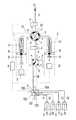
低圧グラジェント送液システムの基本機構は、流体またはその混合物を送るポンプユニット1、ポンプユニット2、クロマトグラフィー等の分析システム圧力をモニタリングするシステム圧力センサー3、吸入流路Y、ループ51、ループ52の内部圧力およびポンプユニット1、ポンプユニット2の内部圧力を測定する内部圧力センサー4、ループ51またはループ52を介して供給流路Xと前記吸入流路Y、又は前記吸入流路Yと前記ポンプユニット1もしくは前記ポンプユニット2を接続するためのスイッチングバルブたる多方バルブ(ここでは8方バルブ)5、前記吸入流路Yと溶液流路Wの接続および隔絶、又は前記吸入流路Yと排出流路Zの接続および隔絶を可能とする1−4方または1−3方スイッチングバルブたる吸入バルブ6、それぞれ前記ポンプユニット1のポンプチャンバー11と前記ポンプユニット2のポンプチャンバー12の内に往復運動し、ポンプシール15と16を有するプランジャー13と14及びそれを駆動するリニアアクチュエーター9と10、前記システム圧力センサー3と前記内部圧力センサー4の測定値を比較し、プランジャーのストローク長などの所定値に基づいて、前記多方バルブ5と前記吸入バルブ6の切り換え、前記リニアアクチュエーター9と10の駆動を制御する制御部8から構成されている。
又、該基本機構は、吸入バルブ6に連通してグラジェントバルブ700を設け、グラジェントバルブ700には複数の溶液貯蔵槽75,76,77,78を電磁弁701,702,703,704、インレット71,72,73,74を介して接続してある。Hereinafter, low pressure gradient liquid feeding using the device of the present invention will be described.
The basic mechanism of the low-pressure gradient liquid feeding system includes a
The basic mechanism is provided with a
圧力センサー3,4は、圧力を電気的な信号に変換する半導体素子またはピエゾ素子(圧電素子)からなる検知部、前記検知部をケーシングするケース、検知した信号を出力・増幅するための内蔵回路から構成されている。また、該圧力センサーは、流体の流れる流路、インレットとアウトレット、配管接続部を有する。この圧力センサーは、圧力を計測しようとする流路に用いられる配管の一部として接続してもよく、その配管にかかる圧力を測定し、電気的な信号として出力される。 The
制御部8は、圧力センサーからの圧力情報(センサーからの信号)、プランジャーの位置情報(駆動部からの信号)、ユーザーが指定した流速などの入力情報(インターフェースからの信号)を基に記憶し、内部での演算を行ない、プランジャーを駆動するリニアアクチュエーター9,10及びスイッチングバルブ5,6,グラジェントバルブ700を動作させる信号を出力する機構の全体を合わせたコンピューターを制御部8と称する。 The
ポンプユニット1,2は、夫々ポンプチャンバー11,12内を往復運動し、且ポンプシール15,16されるプランジャー13,14とプランジャー13,14を駆動するリニアアクチュエーター9,10より構成される。これらポンプユニット1,2に於いて、プランジャー13,14を駆動するリニアアクチュエーター9,10はステップモーター、マイクロステップモーター等を使用し、減速歯車モジュールや軸受、ナット等による直線送動変換機構等の従来各種公知機構を使用して行なわれる。 The
ポンプユニット1,2は多方バルブ5の夫々ポートC,Gに接続してあり、多方バルブ5はここでは多方バルブたる8方弁を使用している。多方バルブ5のポートAには、受取り装置たるクロマトグラフィー等の分析システムX1への供給流路Xが、システム圧力センサー3を介して接続されている。
又、多方バルブ5にはそのポートEに、内部圧力センサー4を介して吸入バルブ6に接続する吸入流路Yが、そのポートaに接続されている。吸入バルブ6には、そのポートeに排出流路Z、例えばドレインチューブが連結してあり、そのポートaと連通するポートcにはグラジェントバルブ700を介して、溶液貯蔵槽75,76,77,78が連結してある。The
The
システム圧力センサー3は、多方バルブ5に連結した分析システムX1への供給流路Xの圧力、即ちクロマトグラフィー等X1のシステム圧力を感知するものである。内部圧力センサー4は、供給流路Yに設置され、多方バルブ5を介して、ポンプユニット1及びポンプユニット2に連結され、ポンプユニット1及びポンプユニット2及び吸入流路Yの圧力を測定し、制御部8に連結している。
吸入バルブ6は、吸入流路Yとグラジェントバルブ700の接続及び隔絶、また吸入流路Yと排出流路Zの接続及び隔絶を行なっている。The
The suction valve 6 connects and isolates the suction flow path Y and the
ポンプユニット1,2の作動制御のための制御部8は前記システム圧力センサー3と前記内部圧力センサーの測定値により、又ポンプチャンバー11,12を往復動するプランジャー13,14のストローク長を得て、それを駆動するリニアアクチュエーター9,10の駆動を制御する如く構成されている。又、多方バルブ5のポートB,D間とポートF,H間は夫々チューブにより接続され、ループ51、ループ52が形成されている。該多方バルブ5の8方スイッチングバルブは、4方スイッチングバルブを使用することも可能である。吸入バルブ6のポートbとdとは、プラグ栓で密栓するのが便である。 The
ここで使用されるグラジェントバルブ700は、例えば溶液貯蔵槽75,76,77,78に収容の4種類の溶液O、P、Q、Rに対して夫々4つのインレット71,72,73,74と4つの開閉電磁弁701,702,703,704を有する。開閉電磁弁が開いた場合に、前記の溶液がバルブ中央部の共通アウトレットSからポンプユニット1もしくはポンプユニット2により吸引される。予め設定されたグラジェントプログラムに従って、前期の複数開閉電磁弁が混合組成に等しい時間比例に基づいて開閉を繰り返すと共に、共通アウトレットSでの混合された溶液は、ポンプユニット1もしくはポンプユニット2により吸引され、トータル容積が極めて小さい溶液流路W、吸入バルブ6と供給流路Yを通って、多方バルブ5に取り付けられたループ51もしくはループ52内に入る。 The
ループ51に入った一定組成または一定組成範囲の混合溶液は、多方バルブ5を切り換えた後に、ポンプユニット1により分析システムへの供給流路Xを介して、クロマトグラフィー等の分析システムX1へ送られる。ループ51の混合溶液を送出した直後に、スイッチングバルブ5を反対方向に切り換え、ループ52に入った混合溶液がポンプユニット2により分析システムX1へ送られる。ループ51とループ52に交互に充満させた混合溶液の組成が、グラジェントプログラムに基づいて経時変化し、ポンプユニット1とポンプユニット2により交互に分析システムX1へ送られる。供給される混合溶液の各セグメントは前後に繋ぎ、流れ方向に沿って正しい組成変化が形成される。混合溶液組成の経時変化は直線的なものが多いが、階段状、指数的、対数的なものもある。制御部8が設定されたグラジェントプログラムに基づいて、グラジェントバルブ700を制御し、開閉電磁弁により混合溶液を組成し、前記の如き送液により低圧グラジェント溶出システムを制御する。 After the
低圧グラジェント送液システムの基本動作と制御
(a)複数の溶液O、P、Q、Rは、グラジェントバルブ700によって、その組成比を制御されると共に、多方バルブ5のポートE,F間とH,G間が連通され、且吸入バルブ6のポートa,c間が連通された状態でポンプユニット1が混合溶液を吸引し、ループ51内を満たす。
(b)多方バルブ5が切り換り、A,H間、F,G間、B,C間、D,E間が連通される。
(c)ポンプユニット1により、ループ51内の溶液が供給流路Xを通って分析システムX1へ供給される。その時、ポンプユニット2は新たな組成比の溶液を吸引し、ループ52内を満たす。Basic operation and control of low-pressure gradient liquid feeding system (a) The composition ratio of a plurality of solutions O, P, Q, and R is controlled by a
(B) The
(C) The solution in the
(d)ループ52内が溶液で満たされた後、吸入バルブ6がポートa,d連通に切り換り、吸入流路Yが密栓される。
(e)ポンプユニット1の送液により、供給流路X内の圧力上昇がシステム圧力センサー3に感受され、その測定値は制御部8に伝えられる。一方、ポンプユニット2は溶液を加圧し、ポンプチャンバー12内の圧力はセンサー4に感知され、その内部圧力がシステム圧力と同等に加圧され、待機する。
(f)ポンプユニット1がループ51内の溶液を全て分析システムX1へ供給した直後に、多方バルブ5はポートA,B間、C,D間、E,F間、G,H間が連通される状態からF,G間、A,H間、B,C間、D,E間が連通される状態に、吸入バルブ6はポートa,c間が連通される状態に切り換る。(D) After the inside of the
(E) Due to the liquid feeding of the
(F) Immediately after the
(g)ポンプユニット2がループ52内の溶液を吐出し、分析システムX1へ溶液が供給される。この時、ポンプユニット1は新たな組成比の溶液を高速吸引し、吸入流路Y、溶液流路Wおよびループ51などを洗浄する。吸入バルブ6はポートa,e間が連通される状態に切り換えられ、洗浄液を排出流路Zを通って吐出する。吸入バルブ6は再びポートa,c間が連通される状態に切り換えられ、ポンプユニット1は新たな組成比の溶液を高速吸引し、ループ51内を満たす。(G) The
(h)ループ51内が溶液で満たされた後、スイッチングバルブ6がポートa,dに切り換り、吸入流路Yが密栓される。
(i)ポンプユニット1は、チャンバー11内の溶液を圧縮し、その圧力が供給流路Xの圧力センサー3の圧力(システム圧力)と同等になるようになるまで、ポンプ1が溶液を加圧し、待機する。
(a)から(i)の動作を連続して行なうことで、グラジェントを生成させる。(H) After the inside of the
(I) The
A gradient is generated by continuously performing the operations (a) to (i).
低圧グラジェント法では、それぞれの溶液が入っている溶液貯蔵槽から目的の混合比率の溶液を作成する工程が必要不可欠となる。この混合溶液作成の調整を行なうのが、グラジェントバルブ700である。このバルブは、上記に述べた如く開閉電磁弁である。つまり、開口と閉鎖の2つの状態しか持ち合わせないため、開口率(開口部分の大きさ)を調整して混合溶液を作成することは出来ない。このバルブを用いて混合溶液を作成するには、混合比率に応じた開口時間を設定する事により、混合溶液の作成が可能となる。 In the low pressure gradient method, a step of preparing a solution having a target mixing ratio from a solution storage tank containing each solution is indispensable. The
例えば、A液:B液=80%:20%を5μL/min1分間で送液するために混合溶液を作成する場合、5μL/minでポンプチャンバー内に吸引される時に、A液のバルブの開口時間を0.8分、B液の開口時間を0.2分とする事で作成可能である。しかし、この条件ではA液とB液は完全には混合されずに、層となって送液される恐れがある。これを解決する方法として、単位時間に区切ってその中でA液およびB液のバルブの開口を繰り返すことにより、混合比率をより正確(均一)に出来る。つまり上述の例で言えば、A液の開口を0.08分、B液の開口を0.02分行なう動作を10回繰り返す事によって、より正確(均一)な混合比率で行なうことが出来る。この単位時間は、より短いほうが混合溶液の均一性は向上する事になる。実際に単位時間を設定する場合は、使用するバルブ制御の性能および使用溶液の混合のし易さに依存するものである。 For example, when preparing a mixed solution to send liquid A: liquid B = 80%: 20% at 5 μL / min for 1 minute, when the liquid is sucked into the pump chamber at 5 μL / min, the valve opening of liquid A is opened. It can be created by setting the time to 0.8 minutes and the B liquid opening time to 0.2 minutes. However, under these conditions, the liquid A and the liquid B are not completely mixed and may be fed as a layer. As a method for solving this, the mixing ratio can be made more accurate (uniform) by dividing the unit A into unit time and repeating the opening of the A liquid and B liquid valves therein. That is, in the above example, the operation of opening the A liquid for 0.08 minutes and the B liquid for 0.02 minutes is repeated 10 times, so that the mixture can be performed with a more accurate (uniform) mixing ratio. The shorter the unit time, the better the uniformity of the mixed solution. When the unit time is actually set, it depends on the performance of the valve control to be used and the ease of mixing the used solution.
上記のように、調整された混合溶液をグラジェントとなるようにクロマトグラフィーシステムに送液する低圧グラジェント方法として下記の2種類がある。
1.低圧グラジェント方法1:ループ内単一組成ステップ
この方法は、低圧グラジェント用基本構造図1に示したループ51、ループ52から交互に単一組成の溶液を順次送液する事により、ステップグラジェントを形成する方法である。
つまり、ステップ毎に送出されるループが切り換わりながら、グラジェントを形成する。例として、A液:B液が100%:0%から0%:100%までを10ステップで行なうとする。As described above, there are the following two types of low-pressure gradient methods for feeding the adjusted mixed solution to the chromatography system so as to form a gradient.
1. Low Pressure Gradient Method 1: Single Composition Step in Loop This method is a step structure in which a single composition solution is alternately fed from the
That is, a gradient is formed while the loop sent out at each step is switched. As an example, assume that liquid A: liquid B is performed in 10 steps from 100%: 0% to 0%: 100%.
(1)システムの平衡化のために、初期組成であるA液:B液=100%:0%を送液
する。グラジェントバルブ700は、A液のみが開口(連通)され、基本的な連続送液動作が行なわれる。
(2)グラジェントの開始
1)ポンプユニット2が上死点に達すると、バルブ5の切り換えと同時にポンプユ
ニット1から100%:0%溶液が送液され始める。同時に、ポンプユニット2はグラジェントバルブ700を介して、混合比90%:10%の溶液がループ52内に充填され、予備加圧される。
2)ポンプユニット1による初期組成溶液の設定時間分の送液が完了した段階で、
バルブ5の切り換えと同時にポンプユニット2によるループ52内の溶液(90%:10%)の送液が開始される。(1) For equilibration of the system, liquid A: B liquid = 100%: 0% which is the initial composition is sent. In the
(2) Start of gradient 1) When
2) At the stage when the
Simultaneously with the switching of the
3)ポンプユニット1のシリンダ及びループ51内には、設定時間で送出されなかった残存溶液が存在するため、吸入バルブ6のポートeを介して排出する。(ポンプユニット2は送液中)
4)次いで、次の組成の溶液をグラジェントバルブ700を介してループ51に充填し、予備加圧を行なう。(ポンプユニット2は送液中)
5)ポンプユニット2による設定時間分の送液が完了すると共に、バルブ5の切り換えと同時に、ポンプユニット1の送液が開始される。
6)以降、2)からの繰り返し(低圧グラジェントバルブによる組成調整は変化する)3) Since there is a residual solution that has not been delivered in the set time in the cylinder and
4) Next, a solution having the following composition is filled into the
5) Liquid supply for the set time by the
6) After that, repeat from 2) (Composition adjustment by low pressure gradient valve changes)
上記の設定を表にすると、以下のようになる。
以下、本発明装置一実施例のポンプ動作を表にして示す。
多方バルブ5のバルブポジションは、以下に示すように略する。
バルブポジション「1」…ポートA,B、C,D、E,F、G,Hが連通状態
バルブポジション「2」…ポートB,C、D,E、F,G、H,Aが連通状態
Hereinafter, the pump operation of the embodiment of the present invention device is shown in a table.
The valve position of the
Valve position “1”: Ports A, B, C, D, E, F, G, H are in communication state Valve position “2”: Ports B, C, D, E, F, G, H, A are in communication state
低圧グラジェント方式の説明に於いては、説明の便宜上、10%刻みのステップグラジェントを例として用いたが、ステップ間の混合比率推移および混合比率毎の継続時間を単位時間当たり極限的に細分割する事によって、リニアグラジェントと同様のグラジェントを形成できる。本方法では、ステップ保持時間内に、「残存溶液の排出」「溶液の吸引」「予備加圧」の3行程を行なう必要があるため、ステップ数の設定はこれらの行程のスピードに依存する。 In the description of the low-pressure gradient method, a step gradient in 10% increments is used as an example for convenience of explanation, but the transition of the mixing ratio between steps and the duration for each mixing ratio are extremely limited per unit time. By dividing, a gradient similar to a linear gradient can be formed. In this method, since it is necessary to perform three steps of “discharge of residual solution”, “suction of solution”, and “pre-pressurization” within the step holding time, the setting of the number of steps depends on the speed of these steps.
2.低圧グラジェント方法2:ループ内グラジェント形成
この方法は、ポンプユニットの吸引時にループ内に一定範囲のグラジェント(複数のステップ)を形成させ、それを順次送液し続ける事により、全体としてグラジェントを形成させる方法である。
基本的な動作は、上記の低圧グラジェント方法1と同様であるが、方法1がループ内に充填する送液が単一組成であったのに対して、方法2(ループ内グラジェント法)に於いては、ループ内に溶液を吸引する際に低圧グラジェントバルブ700の電磁弁の開口時間比率を経時的に変化させる事によって、ループ内にグラジェントを形成させた溶液が充填される。2. Low-pressure gradient method 2: In-loop gradient formation This method forms a gradient (multiple steps) in the loop at the time of suction of the pump unit, and continuously feeds the gradient so that the entire gradient is obtained. This is a method of forming a gent.
The basic operation is the same as that of the low-
このようにポンプユニットは基本送液動作を行ないながら、グラジェントバルブ700の開口時間比率を経時的に変化するように調整する事により、システムにグラジェント溶液を送液する事が可能となる。
実際は、グラジェントバルブ700は、ステップ状の溶液混合しか行えないため、ループ内に充填されるグラジェント溶液も厳密にはステップ状である。In this manner, the pump unit can perform the basic liquid feeding operation, and adjust the opening time ratio of the
Actually, since the
1 ポンプユニット
2 ポンプユニット
3 システム圧力センサー
4 内部圧力センサー
5 多方バルブ
6 吸入バルブ
8 制御部
9 リニアアクチュエーター
10 リニアアクチュエーター
11 ポンプチャンバー
12 ポンプチャンバー
13 プランジャー
14 プランジャー
15 ポンプシール
16 ポンプシール
17 試料導入ユニット
51 ループ
52 ループ
71 インレット
72 インレット
73 インレット
74 インレット
75 溶液貯蔵槽
76 溶液貯蔵槽
77 溶液貯蔵槽
78 溶液貯蔵槽
700 グラジェントバルブ
701 電磁弁
702 電磁弁
703 電磁弁
704 電磁弁
A ポート
B ポート
C ポート
D ポート
E ポート
F ポート
G ポート
H ポート
Q 溶液混合具
U 流路
W 溶液流路
X 供給流路
X1 分析システム
Y 吸入流路
Z 排出流路
a ポート
b ポート
c ポート
d ポート
e ポートDESCRIPTION OF
Claims (7)
Translated fromJapanesePriority Applications (1)
| Application Number | Priority Date | Filing Date | Title |
|---|---|---|---|
| JP2006159068AJP4732960B2 (en) | 2006-06-07 | 2006-06-07 | Gradient liquid feeding method and apparatus |
Applications Claiming Priority (1)
| Application Number | Priority Date | Filing Date | Title |
|---|---|---|---|
| JP2006159068AJP4732960B2 (en) | 2006-06-07 | 2006-06-07 | Gradient liquid feeding method and apparatus |
Publications (2)
| Publication Number | Publication Date |
|---|---|
| JP2007327846A JP2007327846A (en) | 2007-12-20 |
| JP4732960B2true JP4732960B2 (en) | 2011-07-27 |
Family
ID=38928411
Family Applications (1)
| Application Number | Title | Priority Date | Filing Date |
|---|---|---|---|
| JP2006159068AExpired - Fee RelatedJP4732960B2 (en) | 2006-06-07 | 2006-06-07 | Gradient liquid feeding method and apparatus |
Country Status (1)
| Country | Link |
|---|---|
| JP (1) | JP4732960B2 (en) |
Families Citing this family (9)
| Publication number | Priority date | Publication date | Assignee | Title |
|---|---|---|---|---|
| DE102008006266B4 (en) | 2008-01-25 | 2011-06-09 | Dionex Softron Gmbh | Sampler for liquid chromatography, in particular for high performance liquid chromatography |
| AU2009347432B2 (en)* | 2009-06-03 | 2015-01-29 | Agilent Technologies, Inc. | Sample injector with metering device balancing pressure differences in an intermediate valve state |
| JP6055720B2 (en)* | 2013-05-27 | 2016-12-27 | 株式会社日立ハイテクノロジーズ | Liquid chromatograph |
| DE202016100451U1 (en) | 2015-06-25 | 2016-02-16 | Dionex Softron Gmbh | Sampler for liquid chromatography, in particular for high performance liquid chromatography |
| WO2017006410A1 (en)* | 2015-07-06 | 2017-01-12 | 株式会社島津製作所 | Autosampler and liquid chromatograph |
| CN112740029B (en)* | 2018-11-14 | 2023-08-04 | 株式会社岛津制作所 | Low-pressure gradient liquid delivery system and liquid chromatograph |
| CN110057814B (en)* | 2019-05-16 | 2025-01-24 | 山东省科学院海洋仪器仪表研究所 | High-precision seawater pH in-situ measurement system and method based on integrated valve island device |
| CN112697989B (en)* | 2020-12-07 | 2024-07-02 | 赛默飞世尔(上海)仪器有限公司 | Water quality analyzer, liquid taking and delivering method for water quality analyzer and water quality on-line monitoring system |
| CN115166119B (en)* | 2022-06-30 | 2024-06-14 | 华谱科仪(北京)科技有限公司 | High-precision low-pressure gradient method of high-performance liquid chromatograph |
Family Cites Families (9)
| Publication number | Priority date | Publication date | Assignee | Title |
|---|---|---|---|---|
| JPH02238358A (en)* | 1989-03-13 | 1990-09-20 | Shimadzu Corp | Method for controlling solvent composition in liquid chromatograph |
| JP3491948B2 (en)* | 1993-03-05 | 2004-02-03 | ウォーターズ・インベストメンツ・リミテッド | Solvent pump feeder |
| JP2636699B2 (en)* | 1993-09-07 | 1997-07-30 | 株式会社島津製作所 | Liquid chromatograph |
| JPH07280789A (en)* | 1994-04-13 | 1995-10-27 | Sekisui Chem Co Ltd | Liquid chromatography |
| JP2003098166A (en)* | 2001-09-27 | 2003-04-03 | Gl Sciences Inc | Liquid sending method and gradient method of liquid chromatography |
| JP2003185646A (en)* | 2001-12-13 | 2003-07-03 | Moore Kk | High-pressure stepwise gradient of liquid delivering system |
| JP4077674B2 (en)* | 2002-07-24 | 2008-04-16 | 憲一 工藤 | Gradient liquid feeding device and liquid feeding method for nano / micro liquid chromatograph |
| JP3898688B2 (en)* | 2003-11-07 | 2007-03-28 | 株式会社日立ハイテクノロジーズ | Gradient liquid feeder |
| JP4254958B2 (en)* | 2004-06-09 | 2009-04-15 | 株式会社日立ハイテクノロジーズ | Gradient liquid feeding system |
- 2006
- 2006-06-07JPJP2006159068Apatent/JP4732960B2/ennot_activeExpired - Fee Related
Also Published As
| Publication number | Publication date |
|---|---|
| JP2007327846A (en) | 2007-12-20 |
Similar Documents
| Publication | Publication Date | Title |
|---|---|---|
| JP4732960B2 (en) | Gradient liquid feeding method and apparatus | |
| JP4812524B2 (en) | Liquid supply method and apparatus | |
| US20230135114A1 (en) | Sample Injector With Metering Device Balancing Pressure Differences In An Intermediate Valve State | |
| CN107449851B (en) | Sample injection using a fluid connection between a fluid drive unit and a sample receiving space | |
| US7278329B2 (en) | Chromatography system with blockage determination | |
| US7921696B2 (en) | Liquid chromatograph device | |
| JP3491948B2 (en) | Solvent pump feeder | |
| US8160751B2 (en) | Devices, systems and methods for flow-compensating pump-injector synchronization | |
| CN105308448B (en) | Metering device switchable between different fluid paths cleaned by solvent from the analytical path of the fluid separation system | |
| US20080047611A1 (en) | Fluid pump having low pressure metering and high pressure delivering | |
| US10473632B2 (en) | Metering device with defined enabled flow direction | |
| JP2004150402A (en) | Liquid chromatograph pump | |
| US20140318224A1 (en) | High-pressure constant flow rate pump and high-pressure constant flow rate liquid transfer method | |
| JP4377900B2 (en) | Liquid chromatograph | |
| EP2665549A1 (en) | Gradient systems and methods | |
| US20240060939A1 (en) | Sample metering and injection for liquid chromatography | |
| EP3759382B1 (en) | System and valve for liquid chromatography | |
| JP4732961B2 (en) | Gradient liquid feeding method and apparatus | |
| JP2006118374A (en) | Liquid feeding system | |
| WO2006087037A1 (en) | Fluid pump having high pressure metering and high pressure delivering |
Legal Events
| Date | Code | Title | Description |
|---|---|---|---|
| A621 | Written request for application examination | Free format text:JAPANESE INTERMEDIATE CODE: A621 Effective date:20090421 | |
| A977 | Report on retrieval | Free format text:JAPANESE INTERMEDIATE CODE: A971007 Effective date:20110316 | |
| A01 | Written decision to grant a patent or to grant a registration (utility model) | Free format text:JAPANESE INTERMEDIATE CODE: A01 Effective date:20110322 | |
| A61 | First payment of annual fees (during grant procedure) | Free format text:JAPANESE INTERMEDIATE CODE: A61 Effective date:20110421 | |
| FPAY | Renewal fee payment (event date is renewal date of database) | Free format text:PAYMENT UNTIL: 20140428 Year of fee payment:3 | |
| R150 | Certificate of patent or registration of utility model | Free format text:JAPANESE INTERMEDIATE CODE: R150 | |
| R250 | Receipt of annual fees | Free format text:JAPANESE INTERMEDIATE CODE: R250 | |
| LAPS | Cancellation because of no payment of annual fees |