JP4732491B2 - Vehicle equipment - Google Patents
Vehicle equipmentDownload PDFInfo
- Publication number
- JP4732491B2 JP4732491B2JP2008195334AJP2008195334AJP4732491B2JP 4732491 B2JP4732491 B2JP 4732491B2JP 2008195334 AJP2008195334 AJP 2008195334AJP 2008195334 AJP2008195334 AJP 2008195334AJP 4732491 B2JP4732491 B2JP 4732491B2
- Authority
- JP
- Japan
- Prior art keywords
- vehicle
- light receiving
- receiving sensor
- illuminance
- mirror
- Prior art date
- Legal status (The legal status is an assumption and is not a legal conclusion. Google has not performed a legal analysis and makes no representation as to the accuracy of the status listed.)
- Expired - Fee Related
Links
Images


Classifications
- B—PERFORMING OPERATIONS; TRANSPORTING
- B60—VEHICLES IN GENERAL
- B60J—WINDOWS, WINDSCREENS, NON-FIXED ROOFS, DOORS, OR SIMILAR DEVICES FOR VEHICLES; REMOVABLE EXTERNAL PROTECTIVE COVERINGS SPECIALLY ADAPTED FOR VEHICLES
- B60J3/00—Antiglare equipment associated with windows or windscreens; Sun visors for vehicles
- B60J3/04—Antiglare equipment associated with windows or windscreens; Sun visors for vehicles adjustable in transparency
Landscapes
- Engineering & Computer Science (AREA)
- Mechanical Engineering (AREA)
- Electrochromic Elements, Electrophoresis, Or Variable Reflection Or Absorption Elements (AREA)
Description
Translated fromJapanese本発明は、フロントガラスに貼り付けられてサンバイザーとして機能する調光シートと、車両の後方視界を確保するためのルームミラーとを含む車両装備品に関するものである。 The present invention relates to a vehicle accessory including a light control sheet that is attached to a windshield and functions as a sun visor, and a room mirror for securing a rear view of the vehicle.
車両走行中、太陽光が運転者の目に入り、その眩しさから前方確認が困難になることがある。そこで、特許文献1のようなサンバイザーが従来用いられている。特許文献1記載のサンバイザーは、フロントガラスの上部に固定されるケース本体と、ケース本体に進退可能に収容された遮光板と、ケース本体に突設され車両の前方から入射した太陽光を検出する2つの受光センサと、を備えている。一方の受光センサは運転手の目線より僅か下方に位置しており、他方の受光センサは太陽光の入射線と運転者の目線とを結ぶ線上に位置している。少なくともどちらかの受光センサが光を検出している間は、遮光板がケース本体から突出して太陽光を遮る。その後、いずれの受光センサも光を検出しなくなると、遮光板は後退してケース本体に収容される。
特許文献1記載のサンバイザーでは、機械的な動きを伴うため、構成が複雑になる。また、2つの受光センサの位置を正確に調整する必要があり、調整が不十分だと、運転者が眩しいと感じているにもかかわらず遮光板がケース本体から出てこないことがある。 The sun visor described in
そこで本発明は、機械的に動作させることなく太陽光を確実に遮光できる車両装備品を提供することを目的とする。 Then, an object of this invention is to provide the vehicle equipment which can shade sunlight reliably, without operating mechanically.
本発明の車両装備品は、車両のフロントガラスに貼付され、電圧の値に応じて光透過率が変化する調光シートと、車両の後方視界を確保するルームミラーと、を備え、
ルームミラーは、車両前方から入射する太陽光の照度を測定する前方用受光センサと、車内の照度を測定する後方用受光センサと、調光シートへの電圧の印加を制御する回路基板と、を有し、
回路基板は、調光シートに電圧を印加するための、太陽光の照度と車内の照度との組み合わせを予め記憶した記憶手段と、前方用受光センサによって受光される太陽光の照度と後方用受光センサによって受光される車内の照度との組み合わせと、記憶手段に記憶された組み合わせと、を比較し、比較結果に基づいて調光シートに電圧を印加する電圧出力手段と、を含み、
ルームミラーには、フロントガラス側で開口を有する筒状部が設けられ、筒状部の孔内には、前方用受光センサが開口から後退した位置に配置され、筒状部の孔の軸線は、車両の進行方向に沿って延在することを特徴とする。The vehicle equipment of the present invention includes a light control sheet that is affixed to a windshield of a vehicle and whose light transmittance changes according to a voltage value, and a room mirror that secures a rear view of the vehicle,
The rearview mirror includes a front light receiving sensor that measures the illuminance of sunlight incident from the front of the vehicle, a rear light receiving sensor that measures the illuminance in the vehicle, and a circuit board that controls the application of voltage to the light control sheet. Have
The circuit board has a storage means for storing a combination of the illuminance of sunlight and the illuminance in the vehicle for applying a voltage to the light control sheet, and the illuminance of sunlight received by the front light receiving sensor and the rear light reception. A combination of the illuminance in the vehicle received by the sensor and a combination stored in the storage means, and a voltage output means for applying a voltage to the light control sheet based on the comparison result,
The rear-view mirror is provided with a cylindrical portion having an opening on the windshield side, and the front light receiving sensor is disposed at a position retracted from the opening in the hole of the cylindrical portion, and the axis of the hole of the cylindrical portion is It extends along the traveling direction of the vehicle .
この車両装備品によれば、太陽光の遮光は、フロントガラスに貼付した調光シートの光透過率を変化させることで実現できる。よって、部材を機械的に動かすことで遮光する装置に比べて、より電気的に遮光することができる。 According to this vehicle accessory, the shading of sunlight can be realized by changing the light transmittance of the light control sheet attached to the windshield. Therefore, it can shield light more electrically than a device that shields light by mechanically moving the member.
ところで、運転者が太陽光を眩しいと感じるのは、太陽が運転者の頭上にあるときではなく、太陽がフロントガラス越しに見えるときである。太陽が運転者の頭上にあって運転者から見えないときは、車外は明るいが車内は暗い。一方、太陽がフロントガラス越しに見えるときは、太陽光が車内に差し込むため、車外も車内も明るい。よって、前方用受光センサで車両前方からの太陽光の照度を測定し、後方用受光センサで車内の照度を測定することにより、太陽が眩しい位置にあるか否か、換言すると遮光を行うべきか否かを判別することができる。太陽光の照度だけで遮光の要否を判断しようとすると、運転者が眩しいと感じる方向と前方用受光センサの向きとを厳密に調整しなくてはならないが、本実施形態のように太陽光の照度だけではなく車内の照度も測定し、これらの組み合わせに基づいて調光シートを動作させれば、前方用受光センサの位置が多少ずれていても、運転者が眩しいと感じる太陽光を調光シートで確実に遮光できる。 By the way, the driver feels dazzling sunlight not when the sun is above the driver's head, but when the sun is seen through the windshield. When the sun is above the driver and cannot be seen by the driver, the outside of the vehicle is bright but the inside of the vehicle is dark. On the other hand, when the sun can be seen through the windshield, sunlight enters the car, so the outside and the car are bright. Therefore, by measuring the illuminance of sunlight from the front of the vehicle with the front light receiving sensor and measuring the illuminance inside the vehicle with the rear light receiving sensor, whether or not the sun is in a dazzling position, in other words, should the light be blocked? It can be determined whether or not. When trying to determine the necessity of shading only by the illuminance of sunlight, the direction in which the driver feels dazzling and the direction of the front light receiving sensor must be adjusted strictly. By measuring not only the illuminance but also the illuminance in the car and operating the light control sheet based on these combinations, the sunlight that the driver feels dazzling can be adjusted even if the position of the front light receiving sensor is slightly shifted. The light sheet can reliably block light.
また、この車両装備品によれば、太陽光の照度と車内の照度との組み合わせを予め記憶手段に記憶しておき、前方用受光センサによって受光された太陽光の照度と後方用受光センサによって受光された車内の照度との組み合わせと、記憶手段に記憶された組み合わせとを比較し、比較結果に応じて調光シートに電圧を印加する。よって、記憶手段に複数の組み合わせを記憶しておけば、調光シートに対する電圧の印加を細かく制御することができる。
更に、ルームミラーには、フロントガラス側で開口を有する筒状部が設けられ、筒状部の孔内には、前方用受光センサが開口から後退した位置に配置され、筒状部の孔の軸線は、車両の進行方向に沿って延在する。この車両装備品によれば、筒状部の孔の軸線方向と太陽とがなす角度が大きくなると、太陽光が筒状部の孔内に入らなくなり、筒状部の開口から後退した位置にある前方用受光センサは太陽光を受光しなくなる。よって、眩しさが気になる方向からの太陽光と、眩しさが気にならない方向からの太陽光とで、前方用受光センサの測定照度を大きく変えることができる。その結果、調光シートをより正確に動作させることが可能になる。Further, according to this vehicle accessory, the combination of the illuminance of sunlight and the illuminance in the vehicle is stored in advance in the storage means, and the illuminance of sunlight received by the front light receiving sensor and received by the rear light receiving sensor. The combination of the illuminance in the vehicle and the combination stored in the storage means are compared, and a voltage is applied to the light control sheet according to the comparison result. Therefore, if a plurality of combinations are stored in the storage means, it is possible to finely control the application of voltage to the light control sheet.
Further, the rear mirror is provided with a cylindrical portion having an opening on the windshield side, and the front light receiving sensor is disposed at a position retracted from the opening in the hole of the cylindrical portion. The axis extends along the traveling direction of the vehicle. According to this vehicle accessory, when the angle formed by the axial direction of the hole in the cylindrical portion and the sun increases, sunlight does not enter the hole in the cylindrical portion, and is in a position retracted from the opening of the cylindrical portion. The front light receiving sensor does not receive sunlight. Therefore, the measurement illuminance of the front light receiving sensor can be greatly changed between the sunlight from the direction in which the dazzling is concerned and the sunlight from the direction in which the dazzling is not concerned. As a result, the light control sheet can be operated more accurately.
また、ルームミラーは、ミラー板を保持するミラーハウジングと、ミラーハウジングとステーを介して連結されると共にフロントガラスに固定されるベースと、を含み、筒状部は、ルームミラーのベースに設けられていると好適である。この車両装備品によれば、ミラーハウジングを動かしても前方用受光センサの位置は変わらないため、運転者がミラー板の角度を調整すべくミラーハウジングの向きを変えた場合でも、フロントガラスに対する前方用受光センサの位置を一定に保つことができる。The rear mirror includes a mirror housing that holds a mirror plate, and a base that is connected to the mirror housing via a stay and is fixed to the windshield, and thecylindrical portion is provided on the base of the rearmirror. It is preferable that According to this vehicle accessory, since the position of the front light receiving sensor does not change even if the mirror housing is moved, even if the driver changes the direction of the mirror housing to adjust the angle of the mirror plate, The position of the light receiving sensor for use can be kept constant.
また、ルームミラーは、前方用受光センサを、筒状部の孔の軸線に沿って移動させる位置調整手段を有すると好適である。車両の進行方向に対するベースの取り付け角度は、フロントガラスの傾きによって異なる。この角度が異なると、ベースに収容された前方用受光センサの受光角度が変わってしまい、運転者が眩しいと感じる太陽光を受光できなくなってしまうことがある。位置調整手段を有することで、前方用受光センサを筒上部の開口に近づけたり、あるいは遠ざけたりすることが可能となり、その結果、運転者が眩しいと感じる方向からの太陽光を前方用受光センサに確実に受光させることができ、調光シートをより正確に動作させることが可能になる。 In addition, the room mirror preferably includes a position adjusting unit that moves the front light receiving sensor along the axis of the hole of the cylindrical portion. The mounting angle of the base with respect to the traveling direction of the vehicle varies depending on the inclination of the windshield. If this angle is different, the light receiving angle of the front light receiving sensor housed in the base changes, and it may become impossible to receive sunlight that the driver feels dazzling. By having the position adjusting means, the front light receiving sensor can be moved closer to or away from the opening at the top of the cylinder, and as a result, sunlight from the direction that the driver feels dazzling is sent to the front light receiving sensor. Light can be reliably received, and the light control sheet can be operated more accurately.
本発明によれば、機械的に動作させることなく太陽光を確実に遮光することができる。 According to the present invention, sunlight can be reliably shielded without mechanically operating.
以下、図面を参照しつつ本発明に係る車両装備品の好適な実施形態について詳細に説明する。 Hereinafter, preferred embodiments of vehicle equipment according to the present invention will be described in detail with reference to the drawings.
[第1実施形態]
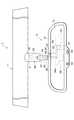
図1〜図3に示すように、車両装備品1は、太陽光による眩しさを防ぐための調光シート7と、車両2の後方視界を確保するためのルームミラー8とを備えている。図1に示すように、調光シートはフロントガラス5に貼付され、ルームミラー8はフロントガラス5に固定されている。[First Embodiment]
As shown in FIGS. 1 to 3, the
調光シート7は可撓性を有する透明シートであって、図1に示すように、フロントガラス5の上側部分に太陽光を遮るように貼付されている。調光シート7は長方形状を呈しており、長手方向がフロントガラス5の延在方向と沿うように貼付される。図2に示すように、調光シート7の下縁(図1のダッシュボード13側に位置する縁)からは調光シート7に電圧を印加するための一対の電極取り出し部9,10が突出しており、この電極取り出し部9,10は調光シート7の長手方向における中央付近に位置している。電極取り出し部9,10は、ルームミラー8のベース68によって覆われている。 The
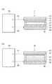
光透過率が変化する調光シート7は、図4(a)に示すように、ゲストホスト液晶層21を一対の透明フィルム15,16の間に設けている。ゲストホスト液晶層21は、液晶と色素とを含む層であり、電圧をかけない時は光をそのまま通すが、電圧をかけるとゲストホスト液晶層21の配向方向が変わって着色状態となり、光透過率が低下する。ゲストホスト液晶層21は一対の配向膜17,19に挟まれており、ゲストホスト液晶層21の周りは接着剤23でシールされている。透明フィルム15,16と配向膜17,19との間には、ゲストホスト液晶層21に電圧を印加するための透明導電膜25,26が設けられている。透明導電膜25,26の一部は接着剤23から突出しており、これが調光シート7の電極取り出し部9,10となる。調光シート7では、ゲストホスト液晶層21を用いることで光の透過可変率を広範囲としている。このような構成の調光シート7は、印加される電圧の大きさに応じて、光透過率が変化する。 As shown in FIG. 4A, the
各構成要素の材料について述べると、透明フィルム15,16の材料としてはPET(ポリエチレンテレフタレート)が例示される。透明フィルム15,16にPETを用いた場合には、調光シート7の可撓性が極めて良好となるうえ、フロントガラス5に対して調光シート7を接着剤で貼り付けることが可能となる。配向膜17,19の材料としてはポリイミド樹脂が例示され、透明導電膜25,26の材料としてはITO(インジウムスズ酸化物)やSnO2(酸化物スズ)が例示される。また、調光シート7は、ゲストホスト液晶層21の光透過率にかかわらず常に無彩色となっている。そのため、調光シート7を貼り付けた状態でも、信号の色や標識等を常に識別することができる。なお、ゲストホスト液晶層21については、無彩色であって、色調をL*a*b*表色系で表したときに、a*、b*値が、プラスマイナス30以下より好ましくはプラスマイナス20であるとする。When the material of each component is described, PET (polyethylene terephthalate) is exemplified as the material of the
図2及び図3に示すように、運転者の斜め前方に配置されたルームミラー8は、樹脂からなるミラーハウジング31を備えている。ミラーハウジング31は、前面が車両2の後方を向き、背面が車両2の前方を向くように設置される。 As shown in FIGS. 2 and 3, the
ミラーハウジング31の前面には、ミラー板33が固定されている。ミラー板33は電圧に応じて光反射率が変化するものであって、電極取り出し部43,44を有している。図4(b)に示すように、ミラー板33では、周りが接着剤42でシールされたエレクトロクロミック層41が一対の透明なガラス板35,36の間に設けられている。エレクトロクロミック層41は、エレクトロクロミック材料と溶媒とを含む層であり、電圧をかけない時は光をそのまま通すが、電圧をかけると酸化還元反応により着色状態となって光透過率が低下する。エレクトロクロミック層41への電圧の印加は、エレクトロクロミック層41を挟む透明導電膜37及び反射膜39を介して行われる。透明導電膜37及び反射膜39は、その一部が接着剤42から突出しており、これがミラー板33の電極取り出し部43,44となる。 A
上記した構成のミラー板33では、透明導電膜37及び反射膜39を介して印加された電圧の値に応じてエレクトロクロミック層41の光透過率が変わり、これによって反射膜39に入射する光量も変わる。そのため、ミラー板33は電圧の大きさに応じて光反射率が変化するものとなる。なお、エレクトロクロミック材料としてはビオロゲンが例示され、溶媒としてはプロピレンカーボネートが例示される。また、透明導電膜37の材料としてはITOやSnO2が例示され、反射膜39の材料としてはRh、Ag、Al、Cr、Ruが例示される。In the
図2に示すように、ミラーハウジング31の前面の中央下側からは、車内の照度を測定するための後方用受光センサ58が露出している。後方用受光センサ58は車両2の後方を向いているため、車両2の後続車から照射された光も検出可能である。後方用受光センサ58は、ミラー板33及び調光シート7に電圧を印加する回路基板54に接続されており、測定照度に応じた電気信号を回路基板54に出力する。 As shown in FIG. 2, a rear
また、ミラーハウジング31の前面の中央下側からは、押しボタン式のスイッチ59が露出している。スイッチ59は、後方用受光センサ58と後述する前方用受光センサ60とのオンオフを制御するためのものであり、スイッチ59がオン状態にあるとき、後方用受光センサ58及び前方用受光センサ60は受光可能になる。 A push
図2及び図3に示すように、回路基板54は、ミラーハウジング31の内部に収容されている。制御用IC54aが搭載された回路基板54は、スイッチ59がオン状態にあるとき、後方用受光センサ58の測定照度と前方用受光センサ60の測定照度とに基づいて、リード線からなる配線61,62を介してミラー板33に電圧を印加すると共に、リード線からなる配線63,64を介して調光シート7に電圧を印加する。回路基板54の動作については、後に詳しく説明する。 As shown in FIGS. 2 and 3, the
図2及び図3に示すように、ミラーハウジング31の内部には、回路基板54に電力を供給するための電源部55が収容されている。電源部55には電池が内蔵されており、電源部55と回路基板54とはリード線からなる配線56,57で接続されている。この配線56,57を通して、電源部55から回路基板54に電力が供給される。電源部55がミラーハウジング31内にあるので、回路基板54に電力を供給するための配線が短くて済む。 As shown in FIGS. 2 and 3, a
図3に示すように、ミラーハウジング31の背面には、ピボット88をボールジョイント構造で連結するための球状凹部31aが形成されている。ピボット88は、フロントガラス5から車室に向けて突出するステー67の一端に設けられており、このピボット88を介してミラーハウジング31はステー67に支持されている。ステー67の他端にはピボット89が設けられており、このピボット89は、フロントガラス5に固定されたベース68の球状凹部68aにボールジョイント構造によって連結されている。 As shown in FIG. 3, a
ステー67及びピボット88,89の内部は中空であり、これらの内部は連通している。また、ピボット88の内部は球状凹部31aに設けられた貫通孔を介してミラーハウジング31の内部と連通しており、ピボット89の内部は球状凹部68aに設けられた貫通孔を介してベース68の内部と連通している。ステー67及びピボット88,89の内部には、ベース68内にある調光シート7の電極取り出し部9とミラーハウジング31内にある回路基板54とをつなぐための配線63と、調光シート7の電極取り出し部10と回路基板54とをつなぐための配線64と、ベース68内にある前方用受光センサ60と回路基板54とをつなぐための配線65が挿通されている。ステー67及びピボット88,89は不透明な樹脂又は金属で成形されているため、配線63〜65は外から見えなくなっている。 The interiors of the
図3に示すように、ステー67を支持するベース68は、フロントガラス5に接着固定された取り付けプレート50に着脱自在に装着される。ベース68は、取り付けプレート50及び取り付けプレート50を弾性保持するためのスプリング75を収容するためのプレート収容空間72と、調光シート7の電極取り出し部9,10を収容するための電極収容空間74とを内部に有している。 As shown in FIG. 3, the base 68 that supports the
プレート収容空間72は、ベース68の第1の壁部76に囲まれている。第1の壁部76は取り付けプレート50と嵌合し、第1の壁部76のうちフロントガラス5の上側に位置する上側壁部76aは、取り付けプレート50に突き当てられている。第1の壁部76を取り付けプレート50と嵌合させ、さらに上側壁部76aを取り付けプレート50に突き当てることにより、ベース68は取り付けプレート50に固定される。上側壁部76aには、プレート収容空間72と電極収容空間74とを連通するための貫通孔78が形成されている。 The
電極収容空間74は、プレート収容空間72よりもフロントガラス5の上側に位置しており、上側壁部76aと、上側壁部76aに対して着脱可能なカバー部材80とで囲まれている。電極収容空間74には、調光シート7の電極取り出し部9,10の他に、車両前方から入射した太陽光の照度を測定するための前方用受光センサ60が収容されている。 The
前方用受光センサ60は、電極収容空間74に設けられた筒状部82に配置されている。筒状部82の一端部は上側壁部76aと一体になっており、筒状部82の一端側の開口84はフロントガラス5に対向している。また、筒状部82の孔の軸線方向は、車両の進行方向と略平行になっている。前方用受光センサ60は、筒状部82の他端側の開口83から挿入されており、筒状部82の一方の開口84から後退した位置に配されている。 The front
筒状部82の孔の軸線上に太陽がある場合には、太陽光が筒状部82の孔内に入射するため、前方用受光センサ60の測定照度が大きくなる。一方、太陽の位置が筒状部82の孔の軸線よりもある程度高くなると、太陽光は筒状部82の孔内に入射しなくなるため、前方用受光センサ60の測定照度は小さくなる。 When the sun is on the axis of the hole of the
前方用受光センサ60及び調光シート7の電極取り出し部9,10からは、回路基板54に繋がる配線63〜65が延びている。これらの配線63〜65は、上側壁部76aの貫通孔78を通ってプレート収容空間72に至り、更にベース68の球状凹部68a、ピボット88、ステー67、ピボット89、ミラーハウジング31の球状凹部31aを通って、ミラーハウジング31内の回路基板54に至っている。なお、カバー部材80が着脱可能なため、カバー部材80を外した状態で電極取り出し部9,10及び前方用受光センサ60と配線63〜65とを繋ぐことができ、配線の接続作業が容易になる。
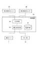
続いて、調光シート7の電極取り出し部9,10及び前方用受光センサ60が接続された回路基板54の動作について、詳しく述べる。制御用IC54aが搭載された回路基板54は、図5に示すように、前方用受光センサ60と後方用受光センサ58とから測定照度に応じた電気信号を受け取る入力手段90と、太陽光の照度と車内の照度との組み合わせが予め記憶された記憶手段91と、入力手段90が前方用受光センサ60と後方用受光センサ58とから受け取った電気信号と記憶手段91に記憶された組み合わせとに基づき調光シート7に電圧を印加する電圧出力手段92と、を有している。 Next, the operation of the
入力手段90が前方用受光センサ60と後方用受光センサ58とから電気信号をそれぞれ受け取ると、電圧出力手段92はこれらの電気信号から、前方用受光センサ60によって受光された太陽光の照度と、後方用受光センサ58によって受光された車内の照度とを特定する。そして、特定した太陽光の照度及び車内の照度と、記憶手段91に記憶された太陽光の照度と車内の照度との組み合わせとを比較し、調光シート7に電圧を印加するか否かを判断する。 When the
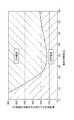
記憶手段91には、調光シート7に電圧を印加するための、車両前方から入射する太陽光の照度と車内の照度との組み合わせが予め記憶されている。図6は、実験で得られた、車両前方から入射する太陽光の照度と、車内の照度と、運転者が感じる眩しさとの関係を示すグラフである。図6に示す「ON領域」は、運転者が眩しいと感じた範囲であり、「OFF領域」は、運転者が眩しいと感じなかった範囲である。記憶手段91には、図6に示す「ON領域」に含まれる車両前方から入射する太陽光の照度と車内の照度との組み合わせが、テーブルとして記憶されている。 The
運転者が眩しさを感じるのは、太陽がフロントガラス越しに見えるときである。太陽がフロントガラス越しに見える場合、太陽光はフロントガラス5を強く照射すると共に、車内にも差し込む。図6において、車両前方から入射する太陽光の照度と、車内の照度とがいずれもある程度大きい領域が「ON領域」(運転者が眩しいと感じた範囲)になるのは、このことによる。 The driver feels dazzled when the sun is seen through the windshield. When the sun can be seen through the windshield, the sunlight shines strongly on the
これに対して、太陽が、運転者から見えないほど高い位置にあるときは、運転者は眩しさを感じない。太陽がこのような位置にある場合、太陽光はフロントガラス5には当たるが車内にはあまり差し込まない。図6において、車両前方から入射する太陽光の照度が大きく、車内の照度が小さい領域が「OFF領域」(運転者が眩しさをさほど感じなかった範囲)になるのは、このことによる。また、日没後・曇天時も、運転者は眩しさを感じない。日没後・曇天時は、車内も車外も暗い。図6において、車両前方から入射する太陽光の照度と車内の照度とが共に小さい領域が「OFF領域」になるのは、このことによる。 On the other hand, when the sun is at a position that is so high that the driver cannot see it, the driver does not feel dazzling. When the sun is in such a position, the sunlight hits the
電圧出力手段92は、前方用受光センサ60によって受光された太陽光の照度と後方用受光センサ58によって受光された車内の照度との組み合わせと、テーブルの内容と、を比較する。前方用受光センサ60によって受光された太陽光の照度と後方用受光センサ58によって受光された車内の照度との組み合わせが、記憶手段91のテーブルに含まれる場合、調光シート7に電圧を印加する。これにより、運転者が眩しさを感じたときに、調光シート7の光透過率を低下させ、太陽光を遮光することができる。一方、前方用受光センサ60によって受光された太陽光の照度と、後方用受光センサ58によって受光された車内の照度との組み合わせが、記憶手段91のテーブルに含まれない場合、電圧出力手段92は調光シート7に対する電圧の印加を禁止する。これにより、運転者が眩しさを感じていないときに調光シート7の光透過率が低下してしまうことがなくなる。 The voltage output means 92 compares the combination of the illuminance of sunlight received by the front
なお、調光シート7に印加する電圧は、前方用受光センサ60によって受光された太陽光の照度に基づく値であっても良く、前方用受光センサ60によって受光された太陽光の照度と後方用受光センサ58によって受光された車内の照度との差分に基づく値であっても良い。また、テーブルを、太陽光の照度と車内の照度との組み合わせに、調光シート7に印加する電圧値を対応付けたものとし、テーブルが示す電圧値を調光シート7に印加してもよい。また、一定値であっても良い。 The voltage applied to the
また、回路基板54の電圧出力手段92は、前方用受光センサ60による測定照度と後方用受光センサ58による測定照度とを比較し、後方用受光センサ58による測定照度の方が多い場合には、これらの差分に応じた電圧を配線61,62を介してミラー板33に印加する。これにより、夜間等に後続車両から強い光が照射された場合には、ミラー板33の光透過率が変化することになり、ミラー板33をいわゆる防眩ミラーとして機能させることができる。なお、本実施形態では、測定照度の差分に応じた電圧をミラー板33に印加するとしたが、後方用受光センサ58による測定照度のみに応じた電圧をミラー板33に印加するとしてもよい。 Further, the voltage output means 92 of the
以上述べたように、車両装備品1では、太陽光の遮光は、フロントガラス5に貼付した調光シート7の光透過率を変化させることによって行われる。よって、部材を機械的に動かすことで遮光する装置に比べ、より電気的に遮光することができる。 As described above, in the
また、車両装備品1では、前方用受光センサ60で車両前方から入射する太陽光の照度を測定し、後方用受光センサ58で車内の照度を測定することにより、太陽が眩しい位置にあるか否か、換言すると遮光を行うべきか否かを判別することができる。前方用受光センサ60の測定結果のみで遮光の要否を判断しようとすると、前方用受光センサ60の向きを運転者が眩しいと感じる太陽の方向に厳密に合わせなくてはならないが、本実施形態のように太陽光の明るさだけではなく車内の明るさも測定すれば、前方用受光センサ60の位置が多少ずれていても、運転者が眩しい時により確実に遮光を行うことが可能になる。 Further, in the
また、車両装備品1では、前方用受光センサ60によって受光された太陽光の照度と後方用受光センサ58によって受光された車内の照度との組み合わせが記憶手段91に記憶された組み合わせであった場合に、調光シート7に電圧を印加する。よって、複数の太陽光の照度と車内の照度との組み合わせを記憶手段91にテーブルとして記憶させれば、調光シート7に対する電圧印加の要否を細かく制御することができる。 Further, in the
また、車両装備品1において、前方用受光センサ60はベース68に収容されているため、ミラーハウジング31を動かしても前方用受光センサ60の位置は変わらない。したがって、運転者がミラー板33の角度調整をした場合でも、フロントガラス5に対する前方用受光センサ60の向きを一定に保つことができる。 In the
また、車両装備品1において、筒状部82は、ベース68という比較的運転者の近くに位置する部材に設けられ、しかも孔の軸線方向が車両の進行方向に沿っている。つまり筒状部82の孔の軸線方向は、運転者の目線とほぼ一致している。よって、筒状部82の孔内にある前方用受光センサ60は、運転者からフロントガラス越しに見える位置に太陽がある場合は、測定照度が大きくなり、運転者から見えないほど太陽が高い位置にある場合は、測定照度が小さくなる。したがって、眩しさが気になる方向からの太陽光と、眩しさが気にならない方向からの太陽光とで、前方用受光センサ60の測定照度を大きく変えることができ、調光シート7をより正確に動作させることが可能になる。 Further, in the
次に、第1実施形態のミラー板33に適用する種々の変形例について説明する。 Next, various modifications applied to the
図7(a)に示すように、第1の変形例であるミラー板120は、一対の透明なガラス板121,122と、ガラス板121,122の間に位置すると共に透明導電膜123,124に挟まれた電解液層125と、を有している。透明導電膜123,124の間には環状の接着剤126が設けられており、接着剤126で囲まれた領域に電解液層125が設けられている。電解液層125と透明導電膜123との間には、WO3からなる層128が形成されている。ガラス板122の透明導電膜124とは反対側の面には反射膜129が設けられ、反射膜129の露出面は保護材130で覆われている。透明導電膜123,124はその一部が接着剤126から突出しており、これがミラー板120の電極取り出し部となって、回路基板54と配線61,62を介して接続される。As shown in FIG. 7A, a
透明導電膜123,124の材料は第1実施形態における透明導電膜37と同様であり、電解液層125の材料は、LiI、LiClO4などの電解質、プロピレンカーボネートなどの溶媒である。反射膜129の材料は第1実施形態における反射膜39と同様である。The materials of the transparent
図7(b)に示すように、第2の変形例であるミラー板140は、透明なガラス板141と、透明導電膜142と、IrOxからなる層143と、Ta2O5からなる層144と、WO3からなる層145と、反射膜146と、透明なガラス板147とがこの順で積層されてなる。透明導電膜142とガラス板147、及び反射膜146とガラス板147は、接着剤148でそれぞれ接合されている。また、透明導電膜142と反射膜146とについても接着剤149で接合されている。ミラー板140では、透明導電膜142と反射膜146とが配線61,62を介して回路基板54と接続される。As shown in FIG. 7B, the
接着剤148,149の材料としてはエポキシ樹脂が例示される。透明導電膜142の材料は第1実施形態における透明導電膜37と同様であり、反射膜146の材料は第1実施形態における反射膜39と同様である。 An example of the material of the
図8(a)に示すように、第3の変形例であるミラー板150は、一対の透明なガラス板151,152と、ガラス板151,152の間に位置する一対の透明導電膜153,154とを有している。透明導電膜153,154は環状の接着剤155で接合されており、接着剤155で囲まれた領域に、一対の配向膜156,157に挟まれたゲストホスト液晶層158が設けられている。透明導電膜154とガラス板152との間には、反射膜159が設けられている。ミラー板150では、透明導電膜153,154が配線61,62を介して回路基板54と接続される。 As shown in FIG. 8A, a
透明導電膜153,154の材料は第1実施形態における透明導電膜37と同様であり、反射膜159の材料は第1実施形態における反射膜39と同様である。配向膜156,157の材料としてはポリイミド樹脂が例示される。 The material of the transparent
図8(b)に示すように、第4の変形例であるミラー板160は、一対の透明なガラス板161,162と、ガラス板161,162の間に位置する一対の透明導電膜163,164とを有している。透明導電膜163,164は環状の接着剤165で接合されており、接着剤165で囲まれた領域に、一対の配向膜166,167に挟まれたゲストホスト液晶層168が設けられている。ガラス板161と透明導電膜163との間にはプラスチックシート169が設けられており、プラスチックシート169はガラス板161に接着剤170で接着固定されている。ガラス板162と透明導電膜164との間には反射膜171が設けられており、反射膜171と透明導電膜164との間にはプラスチックシート172が設けられている。プラスチックシート172は反射膜171に接着剤173で接着固定されている。ミラー板160では、透明導電膜163,164が配線61,62を介して回路基板54と接続される。 As shown in FIG. 8B, a
透明導電膜163,164の材料は第1実施形態における透明導電膜37と同様であり、反射膜171の材料は第1実施形態における反射膜39と同様であり、配向膜166,167の材料は第3の変形例における配向膜156,157と同様である。プラスチックシート169,172の材料としてはPETが例示され、接着剤170,173の材料としてはPVB(ポリビニルブチラール)、EVA(エチレンビニルアセテート)、アクリル、エポキシ樹脂等が例示される。 The materials of the transparent
[第2実施形態]
図9に示すように、第2実施形態に係る車両装備品では、前方用受光センサ60が筒状部82の孔の軸線に沿って移動可能になっている。[Second Embodiment]
As shown in FIG. 9, in the vehicle accessory according to the second embodiment, the front
第2実施形態に係る車両装備品では、前方用受光センサ60が、台座(位置調整手段)202に固定されている。台座202は、その一端側が筒状部82の孔内に収容されており、筒状部82の孔の軸線に沿って進退可能になっている。台座202の一端側は、筒状部82から抜け落ちることがないように、筒状部82の孔内に圧入されている。台座202が筒状部82の孔の軸線方向に摺動することにより、台座202に固定された前方用受光センサ60の、筒状部82の孔内における位置が変わる。そして、前方用受光センサ60の位置が変わることにより、前方用受光センサ60の受光角度が変化する。例えば、筒状部82の開口83寄りにあった前方用受光センサ60を筒状部82の開口84近くに移動させた場合、前方用受光センサ60の受光可能な角度範囲が広くなる。 In the vehicle equipment according to the second embodiment, the front
台座202の他端には、台座の移動量を規制するための鍔部203が設けられており、鍔部203は開口83に挿通不可能な大きさになっている。鍔部203が筒状部82の一端面に当接することで台座202の移動が規制され、開口84からの前方用受光センサ60の突出が防止される。また、台座202及び鍔部203は中空になっており、前方用受光センサ60から延びる配線65が挿通されている。 The other end of the
ベース68の取り付け角度は、車両2の進行方向に対するフロントガラス5の傾きによって異なる。この角度が異なると、ベースに収容された前方用受光センサの受光角度が変わってしまい、運転者が眩しいと感じる太陽光を受光できなくなってしまうことがある。第2実施形態に係る車両装備品では、台座202を移動させることで筒状部82の孔内における前方用受光センサ60の位置を変えることができ、これにより前方用受光センサ60を開口84に近づけたり、あるいは遠ざけたりすることができる。これにより、前方用受光センサ60の受光角度を調整でき、運転者が眩しいと感じる角度からの太陽光を前方用受光センサ60で確実に受光させることが可能になる。よって、遮光が必要な時に調光シート7をより確実に動作させることができる。 The mounting angle of the
[第3実施形態]
図10に示すように、第3実施形態に係る車両装備品では、前方用受光センサ60が第2実施形態とは異なる機構により移動可能になっている。[Third Embodiment]
As shown in FIG. 10, in the vehicle equipment according to the third embodiment, the front
第3実施形態に係る車両装備品では、前方用受光センサ60が、雄螺子224に連結された台座(位置調整手段)222に固定されている。台座222は前方用受光センサ60と共に筒状部82の孔内に収容され、台座222から延びる雄螺子224は筒状部82の一端側の開口83に設けられた雌螺子228と螺合している。雄螺子224と雌螺子228と螺合作用により、台座222に固定された前方用受光センサ60が移動する。筒状部82の孔内において、台座222と筒状部82の一端との間には、雄螺子224の緩みを防止するためのコイルバネ229が設けられている。コイルバネ229は、雄螺子224を取り囲むと共に、台座222と筒状部82の一端とに当接している。 In the vehicle equipment according to the third embodiment, the front
雄螺子224の一端部は、台座222に形成された凹部に収容保持されている。螺合時の雄螺子224の回転が台座222に伝わらないよう、雄螺子224の一端部と台座222の凹部の内周面との間には隙間が設けられている。筒状部82の開口83の外に位置する雄螺子224の他端部には、作業者による把持が可能な操作つまみ229が設けられている。操作つまみ229を回すと雄螺子224が回転し、台座222及び前方用受光センサ60は筒状部82の孔の軸線に沿って進退する。台座222及び雄螺子224の内部には前方用受光センサ60から延びる配線65が挿通されているが、螺合時の雄螺子224の回転が台座222に伝わらない構成となっているため、雄螺子224を回転させても台座222は回転せず、よって配線65の捩れは生じない。 One end of the
第3実施形態に係る車両装備品では、螺合作用により台座222が移動可能になっており、台座222を移動させることによって、筒状部82の孔内における前方用受光センサ60の位置を調整することができ、前方用受光センサ60の位置を調整することで前方用受光センサ60が受光角度を変えることができる。よって、運転者が眩しいと感じる角度からの太陽光を、前方用受光センサ60に確実に受光させることができる。 In the vehicle equipment according to the third embodiment, the
[第4実施形態]
図11に示すように、第4実施形態に係る車両装備品では、筒状部が第3実施形態と異なり、回動可能になっている。[Fourth Embodiment]
As shown in FIG. 11, in the vehicle equipment according to the fourth embodiment, the cylindrical portion is rotatable unlike the third embodiment.
第4実施形態に係る車両装備品では、前方用受光センサ60及び台座222を収容した筒状部252が、上側壁部76aから分離して形成されている。筒状部252には舌片254が設けられており、この舌片254にはピン255を通すための軸穴が形成されている。筒状部252及び舌片254は、軸穴に通されたピン255に軸支され、このピン255を中心に回動可能になっている。またピン255は、筒状部252が振動等で位置ずれしないように軸穴に圧入されている。 In the vehicle equipment according to the fourth embodiment, the
第4実施形態に係る車両装備品では、筒状部252を回動させ、筒状部252の孔の軸線方向を運転者が眩しいと感じる太陽の向きに合わせておけば、この向きから照射される太陽光を筒状部252内の前方用受光センサ60に確実に受光させることができる。その結果、遮光が必要な時に調光シート7をより確実に動作させることができる。なお、本実施形態では舌片254をピン255で軸支することにより筒状部252を回動可能にしているが、ボールジョイント構造を利用しても良い。 In the vehicle equipment according to the fourth embodiment, if the
1…車両装備品、5…フロントガラス、7…調光シート、8…ルームミラー、31…ミラーハウジング、33…ミラー板、58…後方用受光センサ、60…前方用受光センサ、67…ステー、68…ベース、82…筒状部、91…記憶手段、92…電圧出力手段、202,222…台座(位置調整手段)、252…筒状部。 DESCRIPTION OF
Claims (3)
Translated fromJapanese前記ルームミラーは、車両前方から入射する太陽光の照度を測定する前方用受光センサと、車内の照度を測定する後方用受光センサと、前記調光シートへの電圧の印加を制御する回路基板と、を有し、
前記回路基板は、
前記調光シートに電圧を印加するための、前記太陽光の照度と前記車内の照度との組み合わせを予め記憶した記憶手段と、
前記前方用受光センサによって受光される前記太陽光の照度と前記後方用受光センサによって受光される前記車内の照度との組み合わせと、前記記憶手段に記憶された前記組み合わせと、を比較し、比較結果に基づいて前記調光シートに電圧を印加する電圧出力手段と、を含み、
前記ルームミラーには、前記フロントガラス側で開口を有する筒状部が設けられ、前記筒状部の孔内には、前記前方用受光センサが前記開口から後退した位置に配置され、
前記筒状部の前記孔の軸線は、車両の進行方向に沿って延在することを特徴とする車両装備品。A light-adjusting sheet that is affixed to a windshield of a vehicle and whose light transmittance changes according to a voltage value, and a room mirror that secures a rear view of the vehicle,
The room mirror includes a front light receiving sensor that measures the illuminance of sunlight incident from the front of the vehicle, a rear light receiving sensor that measures the illuminance in the vehicle, and a circuit board that controls application of a voltage to the light control sheet; Have
The circuit board is
Storage means for preliminarily storing a combination of the illuminance of sunlight and the illuminance in the vehicle for applying a voltage to the light control sheet;
The combination of the illuminance of the sunlight received by the front light receiving sensor and the illuminance in the vehicle received by the rear light receiving sensor and the combination stored in the storage means are compared, and the comparison result Voltage output means for applying a voltage to the light control sheet based on
The room mirror is provided with a cylindrical portion having an opening on the windshield side, and the front light receiving sensor is disposed at a position retracted from the opening in the hole of the cylindrical portion,
The vehicle equipmentaccording to claim 1, wherein an axis of the hole of the cylindrical portion extends along a traveling direction of the vehicle.
Priority Applications (4)
| Application Number | Priority Date | Filing Date | Title |
|---|---|---|---|
| JP2008195334AJP4732491B2 (en) | 2008-07-29 | 2008-07-29 | Vehicle equipment |
| DE102009020402ADE102009020402A1 (en) | 2008-07-29 | 2009-05-08 | Vehicle accessory |
| US12/466,003US8017896B2 (en) | 2008-07-29 | 2009-05-14 | Vehicle accessory having a rear light receiving sensor for measuring illumination intensity inside the vehicle |
| CN2009101395479ACN101638044B (en) | 2008-07-29 | 2009-06-29 | Vehicle accessory |
Applications Claiming Priority (1)
| Application Number | Priority Date | Filing Date | Title |
|---|---|---|---|
| JP2008195334AJP4732491B2 (en) | 2008-07-29 | 2008-07-29 | Vehicle equipment |
Publications (2)
| Publication Number | Publication Date |
|---|---|
| JP2010030468A JP2010030468A (en) | 2010-02-12 |
| JP4732491B2true JP4732491B2 (en) | 2011-07-27 |
Family
ID=41461808
Family Applications (1)
| Application Number | Title | Priority Date | Filing Date |
|---|---|---|---|
| JP2008195334AExpired - Fee RelatedJP4732491B2 (en) | 2008-07-29 | 2008-07-29 | Vehicle equipment |
Country Status (4)
| Country | Link |
|---|---|
| US (1) | US8017896B2 (en) |
| JP (1) | JP4732491B2 (en) |
| CN (1) | CN101638044B (en) |
| DE (1) | DE102009020402A1 (en) |
Families Citing this family (19)
| Publication number | Priority date | Publication date | Assignee | Title |
|---|---|---|---|---|
| US8786704B2 (en) | 2007-08-09 | 2014-07-22 | Donnelly Corporation | Vehicle mirror assembly with wide angle element |
| JP2012148675A (en)* | 2011-01-19 | 2012-08-09 | Stanley Electric Co Ltd | Sun visor device |
| US8434812B2 (en)* | 2011-07-11 | 2013-05-07 | Ford Global Technologies, Llc | Vehicle visor having mirror assembly |
| US10744947B2 (en)* | 2012-01-24 | 2020-08-18 | SMR Patents S.à.r.l. | Head section for a rear view device |
| DE102012108480B3 (en) | 2012-09-11 | 2014-02-20 | SMR Patents S.à.r.l. | headboard |
| DE102012220192B3 (en)* | 2012-11-06 | 2014-05-22 | Magna Mirrors Holding Gmbh | Auto-dimming rearview mirror assembly for motor vehicles and method of making a mirror assembly for a rearview mirror assembly |
| KR102051656B1 (en)* | 2013-01-22 | 2019-12-03 | 삼성전자주식회사 | Transparent display apparatus and method thereof |
| CN103991366A (en)* | 2013-02-17 | 2014-08-20 | 法国圣戈班玻璃公司 | Sun shading device, vehicle and glass sun shading method |
| KR101592737B1 (en)* | 2014-07-17 | 2016-02-12 | 현대자동차주식회사 | Integrated inside mirror assembly of vehicle |
| DE102015203074B4 (en)* | 2015-02-20 | 2019-11-14 | Bayerische Motoren Werke Aktiengesellschaft | Sensor device, system and method for protecting an occupant, in particular driver, a vehicle from glare and motor vehicle |
| DE102015216999A1 (en)* | 2015-09-04 | 2017-03-09 | Bayerische Motoren Werke Aktiengesellschaft | Interior mirror base assembly for a motor vehicle |
| DE102016101441A1 (en)* | 2016-01-27 | 2017-07-27 | SMR Patents S.à.r.l. | Adjustment system for a rearview element of a rearview device for a vehicle |
| JP6629092B2 (en)* | 2016-02-15 | 2020-01-15 | 株式会社東海理化電機製作所 | Visual recognition device for vehicles |
| US11878575B2 (en)* | 2017-03-31 | 2024-01-23 | Ford Global Technologies, Llc | Vehicle window tinting |
| WO2018227597A1 (en)* | 2017-06-16 | 2018-12-20 | Boe Technology Group Co., Ltd. | Vision-based interactive control apparatus and method of controlling rear-view mirror for vehicle |
| CN112351914B (en)* | 2018-07-10 | 2024-01-23 | 金泰克斯公司 | Optical measurement system for passenger compartment of vehicle |
| DE102018125065B3 (en)* | 2018-10-10 | 2019-11-21 | Bayerische Motoren Werke Aktiengesellschaft | Holding device for holding at least one driver assistance sensor unit and arrangement of a holding device |
| JP7177684B2 (en)* | 2018-12-19 | 2022-11-24 | 株式会社日立製作所 | vehicle controller |
| CN109683421B (en)* | 2019-03-06 | 2022-09-30 | 京东方科技集团股份有限公司 | Refractive index adjusting method and device, smart window and vehicle |
Family Cites Families (15)
| Publication number | Priority date | Publication date | Assignee | Title |
|---|---|---|---|---|
| JPS6049062B2 (en)* | 1979-11-22 | 1985-10-30 | 三井造船株式会社 | Billet feeding device |
| CN2043932U (en)* | 1988-08-29 | 1989-09-06 | 诸殿淙 | Full-automatic dizziness-proof apparatus for driving |
| JPH0535494A (en) | 1991-07-29 | 1993-02-12 | Nec Corp | Interactive optimization compile system for high-level program language |
| JP3103270B2 (en) | 1994-06-07 | 2000-10-30 | 正典 西海 | Automatic sun visor for vehicles |
| CN2415958Y (en)* | 2000-03-15 | 2001-01-24 | 成祠高 | Antiglare device for driver & passenger on vehicle |
| CN1412023A (en)* | 2001-10-16 | 2003-04-23 | 徐文东 | Light-operated intelligent light-barrier for motor vehicle |
| EP1422092B1 (en)* | 2002-11-25 | 2005-11-09 | Fico I.T.M., S.A. | Sun visor with accessories |
| WO2005014319A1 (en) | 2003-08-04 | 2005-02-17 | Robert Bosch Gmbh | Antidazzle system for a vehicle |
| US7014244B1 (en)* | 2005-02-02 | 2006-03-21 | Baldwin Jeffrey B | Auxiliary sun visor |
| JP2006347275A (en)* | 2005-06-14 | 2006-12-28 | Asmo Co Ltd | Sun visor device for vehicle |
| JP2007125984A (en)* | 2005-11-02 | 2007-05-24 | Denso Corp | Vehicular light shielding device |
| JP2007145158A (en)* | 2005-11-28 | 2007-06-14 | Fujitsu Ten Ltd | In-vehicle display device and display control method thereof |
| JP2008044603A (en)* | 2006-07-18 | 2008-02-28 | Tokai Rika Co Ltd | Glare-proof device for vehicle |
| CN101161491A (en)* | 2006-10-13 | 2008-04-16 | 冯冠 | Automobile sun sheet |
| JP2008195334A (en) | 2007-02-15 | 2008-08-28 | Kubota Corp | Variable speed transmission |
- 2008
- 2008-07-29JPJP2008195334Apatent/JP4732491B2/ennot_activeExpired - Fee Related
- 2009
- 2009-05-08DEDE102009020402Apatent/DE102009020402A1/ennot_activeWithdrawn
- 2009-05-14USUS12/466,003patent/US8017896B2/ennot_activeExpired - Fee Related
- 2009-06-29CNCN2009101395479Apatent/CN101638044B/ennot_activeExpired - Fee Related
Also Published As
| Publication number | Publication date |
|---|---|
| US8017896B2 (en) | 2011-09-13 |
| CN101638044B (en) | 2012-09-12 |
| CN101638044A (en) | 2010-02-03 |
| DE102009020402A1 (en) | 2010-02-04 |
| US20100026035A1 (en) | 2010-02-04 |
| JP2010030468A (en) | 2010-02-12 |
Similar Documents
| Publication | Publication Date | Title |
|---|---|---|
| JP4732491B2 (en) | Vehicle equipment | |
| US11794648B2 (en) | Exterior rearview mirror assembly | |
| ES2834890T3 (en) | Rear view mirror assembly without housing | |
| US5223814A (en) | Sensor for vehicle accessories | |
| US9827913B2 (en) | Exterior rearview mirror assembly | |
| EP0144053B1 (en) | Glare-shielding type reflector | |
| JP5577038B2 (en) | Vehicle rear view assembly including high brightness display | |
| EP2817172B1 (en) | Exterior rearview mirror assembly | |
| US20080068717A1 (en) | Auto dimming vehicle mirror | |
| US20090244707A1 (en) | Vehicle accessory | |
| CN210792757U (en) | Light-adjustable sun shield and automobile | |
| US20250026267A1 (en) | Vehicular exterior rearview mirror system | |
| JP2009029245A (en) | Anti-dazzle device for vehicle | |
| CN215971056U (en) | Automobile sun visor with light-adjustable LCD lens and automobile | |
| US11840174B2 (en) | Vehicular overhead console with light transmissive panel | |
| CN212243160U (en) | Mounting structure of automatic anti-glare rearview mirror of automobile | |
| JPH0425174B2 (en) | ||
| CN214564517U (en) | Sun-shading device and automobile | |
| CN219029272U (en) | Light-adjusting rearview mirror | |
| CN219029268U (en) | Dimming rearview mirror with automobile data recorder | |
| CN220577147U (en) | Ultra-thin anti-glare inner rearview mirror | |
| JP2019077366A (en) | Vehicular door mirror device | |
| CN120517147A (en) | Anti-dazzle device for vehicle | |
| JPH0535494U (en) | Vehicle rearview mirror device | |
| KR20130107944A (en) | Sensing module and control device of rear view mirror in a vehicle using the same |
Legal Events
| Date | Code | Title | Description |
|---|---|---|---|
| A621 | Written request for application examination | Free format text:JAPANESE INTERMEDIATE CODE: A621 Effective date:20100611 | |
| A977 | Report on retrieval | Free format text:JAPANESE INTERMEDIATE CODE: A971007 Effective date:20101012 | |
| A131 | Notification of reasons for refusal | Free format text:JAPANESE INTERMEDIATE CODE: A131 Effective date:20101109 | |
| A521 | Request for written amendment filed | Free format text:JAPANESE INTERMEDIATE CODE: A523 Effective date:20110111 | |
| A01 | Written decision to grant a patent or to grant a registration (utility model) | Free format text:JAPANESE INTERMEDIATE CODE: A01 Effective date:20110412 | |
| A01 | Written decision to grant a patent or to grant a registration (utility model) | Free format text:JAPANESE INTERMEDIATE CODE: A01 | |
| A61 | First payment of annual fees (during grant procedure) | Free format text:JAPANESE INTERMEDIATE CODE: A61 Effective date:20110420 | |
| FPAY | Renewal fee payment (event date is renewal date of database) | Free format text:PAYMENT UNTIL: 20140428 Year of fee payment:3 | |
| R150 | Certificate of patent or registration of utility model | Free format text:JAPANESE INTERMEDIATE CODE: R150 | |
| FPAY | Renewal fee payment (event date is renewal date of database) | Free format text:PAYMENT UNTIL: 20140428 Year of fee payment:3 | |
| R250 | Receipt of annual fees | Free format text:JAPANESE INTERMEDIATE CODE: R250 | |
| R250 | Receipt of annual fees | Free format text:JAPANESE INTERMEDIATE CODE: R250 | |
| LAPS | Cancellation because of no payment of annual fees |