JP4732119B2 - Intake control device for saddle-ride type vehicles - Google Patents
Intake control device for saddle-ride type vehiclesDownload PDFInfo
- Publication number
- JP4732119B2 JP4732119B2JP2005303312AJP2005303312AJP4732119B2JP 4732119 B2JP4732119 B2JP 4732119B2JP 2005303312 AJP2005303312 AJP 2005303312AJP 2005303312 AJP2005303312 AJP 2005303312AJP 4732119 B2JP4732119 B2JP 4732119B2
- Authority
- JP
- Japan
- Prior art keywords
- valve shaft
- throttle
- electric motor
- saddle
- vehicle
- Prior art date
- Legal status (The legal status is an assumption and is not a legal conclusion. Google has not performed a legal analysis and makes no representation as to the accuracy of the status listed.)
- Expired - Fee Related
Links
Images


Classifications
- F—MECHANICAL ENGINEERING; LIGHTING; HEATING; WEAPONS; BLASTING
- F02—COMBUSTION ENGINES; HOT-GAS OR COMBUSTION-PRODUCT ENGINE PLANTS
- F02D—CONTROLLING COMBUSTION ENGINES
- F02D11/00—Arrangements for, or adaptations to, non-automatic engine control initiation means, e.g. operator initiated
- F02D11/06—Arrangements for, or adaptations to, non-automatic engine control initiation means, e.g. operator initiated characterised by non-mechanical control linkages, e.g. fluid control linkages or by control linkages with power drive or assistance
- F02D11/10—Arrangements for, or adaptations to, non-automatic engine control initiation means, e.g. operator initiated characterised by non-mechanical control linkages, e.g. fluid control linkages or by control linkages with power drive or assistance of the electric type
- F—MECHANICAL ENGINEERING; LIGHTING; HEATING; WEAPONS; BLASTING
- F02—COMBUSTION ENGINES; HOT-GAS OR COMBUSTION-PRODUCT ENGINE PLANTS
- F02D—CONTROLLING COMBUSTION ENGINES
- F02D9/00—Controlling engines by throttling air or fuel-and-air induction conduits or exhaust conduits
- F02D9/08—Throttle valves specially adapted therefor; Arrangements of such valves in conduits
- F02D9/10—Throttle valves specially adapted therefor; Arrangements of such valves in conduits having pivotally-mounted flaps
- F02D9/1035—Details of the valve housing
- F02D9/105—Details of the valve housing having a throttle position sensor
- F—MECHANICAL ENGINEERING; LIGHTING; HEATING; WEAPONS; BLASTING
- F02—COMBUSTION ENGINES; HOT-GAS OR COMBUSTION-PRODUCT ENGINE PLANTS
- F02D—CONTROLLING COMBUSTION ENGINES
- F02D9/00—Controlling engines by throttling air or fuel-and-air induction conduits or exhaust conduits
- F02D9/08—Throttle valves specially adapted therefor; Arrangements of such valves in conduits
- F02D9/10—Throttle valves specially adapted therefor; Arrangements of such valves in conduits having pivotally-mounted flaps
- F02D9/109—Throttle valves specially adapted therefor; Arrangements of such valves in conduits having pivotally-mounted flaps having two or more flaps
- F02D9/1095—Rotating on a common axis, e.g. having a common shaft
- F—MECHANICAL ENGINEERING; LIGHTING; HEATING; WEAPONS; BLASTING
- F02—COMBUSTION ENGINES; HOT-GAS OR COMBUSTION-PRODUCT ENGINE PLANTS
- F02M—SUPPLYING COMBUSTION ENGINES IN GENERAL WITH COMBUSTIBLE MIXTURES OR CONSTITUENTS THEREOF
- F02M35/00—Combustion-air cleaners, air intakes, intake silencers, or induction systems specially adapted for, or arranged on, internal-combustion engines
- F02M35/16—Combustion-air cleaners, air intakes, intake silencers, or induction systems specially adapted for, or arranged on, internal-combustion engines characterised by use in vehicles
- F02M35/162—Motorcycles; All-terrain vehicles, e.g. quads, snowmobiles; Small vehicles, e.g. forklifts
Landscapes
- Engineering & Computer Science (AREA)
- Chemical & Material Sciences (AREA)
- Combustion & Propulsion (AREA)
- Mechanical Engineering (AREA)
- General Engineering & Computer Science (AREA)
- Control Of Throttle Valves Provided In The Intake System Or In The Exhaust System (AREA)
- Controls For Constant Speed Travelling (AREA)
- Control Of Vehicle Engines Or Engines For Specific Uses (AREA)
Description
Translated fromJapanese 本発明は、鞍乗り型車両の車体フレームに搭載される機関本体のシリンダヘッドに接続される吸気路形成体に、該吸気路形成体に形成される吸気路を横切って車体フレームの左
右方向に延びる弁軸が回動可能に支承され、バタフライ形のスロットル弁が前記吸気路の開度を制御するようにして前記弁軸に固定される鞍乗り型車両における吸気制御装置に関する。The present invention relates to an intake path forming body connected to a cylinder head of an engine body mounted on a body frame of a saddle-ride type vehicle, in a lateral direction of the body frame across the intake path formed in the intake path forming body. The present invention relates to an intake control device in a saddle-ride type vehicle in which an extending valve shaft is rotatably supported and a butterfly throttle valve is fixed to the valve shaft so as to control the opening degree of the intake passage.
車両に搭載される内燃機関の吸気量を制御するために、吸気路形成体に回動可能に支承される弁軸の一端に、電動モータを含むアクチュエータが連結されるようにした吸気制御装置が、たとえば特許文献1で開示されている。
本発明は、コンパクト化を可能とした鞍乗り型車両における吸気制御装置を提供することを目的とする。 It is an object of the present invention to provide an intake control device for a saddle-ride type vehicle that can be made compact.
上記目的を達成するために、請求項1記載の発明は、前端のヘッドパイプと、該ヘッドパイプから左右に分かれて後方に延びる一対のメインフレームとを備えた車体フレームに機関本体が搭載されると共に、その機関本体のシリンダヘッドに接続される吸気路形成体に、該吸気路形成体に並列して形成した複数の吸気路を横切って車体フレームの左右方向に延びる弁軸が回動可能に支承され、この弁軸には、軸方向に並列した複数のバタフライ形のスロットル弁が前記吸気路の開度を制御するようにして固定され、前記弁軸を回動駆動する動力を発揮し得る電動モータを含むアクチュエータが前記弁軸に連結されてなる、鞍乗り型車両における吸気制御装置において、前記弁軸の軸線と平行な回転軸線を有して車両上面視で前記一対のメインフレーム間に配置される前記電動モータが、一部の前記吸気路の側方で前記吸気路形成体に一体に形成した膨出部に設けた収納凹部に収納、支持され、前記アクチュエータは、前記電動モータの回転動力を減速して前記弁軸に伝動する減速ギヤ機構を備えており、それら減速ギヤ機構及び電動モータは、前記吸気路形成体とは別体に形成されて該形成体に取付けたカバーにより覆われていて、それら減速ギヤ機構及び電動モータが、前記吸気路形成体とは別体に形成されて該形成体に取付けたカバーにより覆われており、車両運転者のスロットル操作に応じて回動するスロットルドラムが、前記弁軸の端部に相対回動を可能として装着され、前記吸気路形成体には、前記カバーとは別個独立に構成されて前記スロットルドラムを覆う支持枠が着脱可能に装着されると共に、その支持枠には、前記弁軸と同軸の回転軸線を有して該スロットルドラムに対向配置したスロットル操作量センサが取付けられ、前記弁軸の、前記スロットルドラム側の一端より延びるアームに係合して、前記スロットルドラムの前記弁軸に対する閉じ方向への相対回動を規制可能な突部と、前記スロットル操作量センサに対し前記弁軸の軸線方向に抜差可能に係合して前記スロットルドラムに前記スロットル操作量センサを連動させる係合部とが、前記弁軸の周方向に互いにオフセットした位置で前記スロットルドラムの支持枠側の一側面に設けられることを特徴とする。In order to achieve the above object, according to a first aspect of the present invention, an engine body is mounted on a vehicle body frame including a head pipe at a front end and a pair of main frames that are separated from the head pipe and extend rearward. In addition, a valve shaft extending in the left-right direction of the body frame across the plurality of intake passages formed in parallel to the intake passage formation body is rotatable on the intake passage formation body connected to the cylinder head of the engine body A plurality of butterfly-shaped throttle valves arranged in parallel in the axial direction are fixed to the valve shaft so as to control the opening degree of the intake passage, and the valve shaft can be driven to rotate. An intake control device for a saddle-ride type vehicle, wherein an actuator including an electric motor is coupled to the valve shaft, and has a rotation axis parallel to the axis of the valve shaft and the pair of mains as viewed from above the vehicle The electric motor arranged between the frames is housed and supported in a housing recess provided in a bulging portion formed integrally with the air intake path forming body on a side of a part of the air intake path, and the actuator is A reduction gear mechanism that reduces the rotational power of the electric motor and transmits it to the valve shaft is provided. The reduction gear mechanism and the electric motor are formed separately from the intake passage forming body and are attached to the forming body. wascovered by acover, their reduction gear mechanism and the electricmotor, wherein the air intake path forming body is formed separatelycovered by a cover attached to the transformantadult, the vehicle driver's throttle operation A throttle drum that rotates in response to the valve shaft is attached to the end of the valve shaft so as to be relatively rotatable, and the intake passage forming body is configured independently of the cover and covers the throttle drum. But A throttle operation amount sensor that is mounted detachably and has a rotation axis coaxial with the valve shaft and disposed opposite to the throttle drum is attached to the support frame, and the throttle shaft side of the valve shaft is mounted on the throttle drum side. A protrusion that engages with an arm extending from one end of the throttle drum to restrict relative rotation of the throttle drum in the closing direction with respect to the valve shaft, and is inserted and removed in an axial direction of the valve shaft with respect to the throttle operation amount sensor. An engaging portion that engages the throttle drum with the throttle operation amount sensor in a possible manneris provided on one side surface of the support frame side of the throttle drum at a position offset from each other in the circumferential direction of the valve shaft. theshall be thefeature.
また請求項2記載の発明は、請求項1記載の発明の構成に加えて、前記減速ギヤ機構は、前記電動モータの回転動力を二段階に減速して前記弁軸に伝動すべく、互いに軸方向に隣接配置された2つのギヤ列を備えていて、その一段目のギヤ列の被動側ギヤの外周側方に、前記弁軸の回動位置を検出するスロットル開度センサが配置されることを特徴とする。According to asecond aspect of the present invention, in addition to the configuration of thefirst aspect of the invention, the reduction gear mechanism is configured so that the rotational power of the electric motor is reduced with two stages and transmitted to the valve shaft. A throttle opening sensor for detecting the rotational position of the valve shaft is provided on the outer peripheral side of the driven gear of the first gear train. theshall be thefeature.
また請求項3記載の発明は、請求項1または2記載の発明の構成に加えて、前記機関本体が前記両メインフレームよりも下方に配置され、前記スロットル操作量センサが鞍乗り型車両を側方から見た側面視で前記両メインフレームおよび前記機関本体間に配置される
ことを特徴とする。According to athird aspect of the invention, in addition to the configuration of thefirst orsecond aspect of the invention, the engine main body is disposed below the main frames, and the throttle operation amount sensor is located on the saddle type vehicle. It is arranged between the main frames and the engine body in a side view as viewed from the side.
請求項4記載の発明は、請求項1〜3のいずれかに記載の発明の構成に加えて、前記電動モータが、鞍乗り型車両の前後方向に沿って前記弁軸よりも前方に配置されることを特徴とする。According to afourth aspect of the invention, in addition to the configuration of the invention according to any one of the first tothird aspects, the electric motor is disposed forward of the valve shaft along the front-rear direction of the saddle-ride type vehicle. It is characterized by that.
請求項5記載の発明は、請求項1〜4のいずれかに記載の発明の構成に加えて、水平対向型に構成される前記機関本体が、クランク軸線を鞍乗り型車両の前後方向に沿わせた姿勢で前記車体フレームに搭載され、鞍乗り型車両を側方から見た側面視で前記クランク軸線と略平行にして機関本体の上方に配置される仮想直線上に前記弁軸の軸線および前記電動モータの回転軸線が配置されることを特徴とする。According to afifth aspect of the invention, in addition to the configuration of the invention according to any one of the first tofourth aspects, the engine body configured to be horizontally opposed has a crank axis line along the longitudinal direction of the saddle-ride type vehicle. Mounted on the vehicle body frame in a swaying posture, and the axis of the valve shaft on an imaginary straight line disposed above the engine body in a side view when the saddle riding type vehicle is viewed from the side and substantially parallel to the crank axis. A rotation axis of the electric motor is arranged.
請求項6記載の発明は、請求項1〜5のいずれかに記載の発明の構成に加えて、オートクルーズ状態の選択時に車速を一定に保持するように前記電動モータの作動を制御する制御ユニットと、オートクルーズ状態で前記弁軸の回動に追随するように該弁軸に連動、連結されるスロットルドラムにオートクルーズ状態で車両運転者が閉じ側の操作力を加えるのに応じてスイッチング態様を変化するキャンセルスイッチとを備え、前記制御ユニットは、前記キャンセルスイッチのスイッチング態様変化に応じて前記オートクルーズ状態を解除することを特徴とする。Invention according to
さらに請求項7記載の発明は、請求項1〜6の何れかに記載の発明の構成に加えて、前記両メインフレームよりも下方に前記機関本体が配置され、前記アクチュエータが、車両側面視で前記両メインフレームおよび前記機関本体間に配置されることを特徴とする。Furthermore, in the invention according to
請求項1記載の発明によれば、弁軸の軸線と平行な回転軸線を有し車両上面視で一対のメインフレーム間に配置されて弁軸を駆動する電動モータが、一部の吸気路の側方で吸気路形成体に一体に形成した膨出部に設けた収納凹部に収納、支持される。またその電動モータとそれの回転動力を減速して弁軸に伝動する減速ギヤ機構が、前記吸気路形成体とは別体に形成されて該形成体に取付けたカバーにより覆われる。 According to the first aspect of the present invention, an electric motor that has a rotation axis parallel to the axis of the valve shaft and is disposed between the pair of main frames in a top view of the vehicle and drives the valve shaft, It is housed and supported in a housing recess provided in a bulge formed integrally with the intake passage forming body on the side. The electric motor and a reduction gear mechanism for reducing the rotational power of the electric motor and transmitting it to the valve shaft are formed separately from the intake passage forming body and covered with a cover attached to the forming body.
また車両運転者のスロットル操作に応じて回動するスロットルドラムと、スロットル操作量センサを連結するにあたってリンク機構等の複雑な連結構造が不要であり、スロットルドラムおよびスロットル操作量センサを簡単な連結構造で連結することができる。In addition, a complicated connecting structure such as a link mechanism is not required to connect the throttle drum that rotates according to the throttle operation of the vehicle driver and the throttle operation amount sensor, and the throttle drum and the throttle operation amount sensor are simply connected. Can be connected.
請求項3記載の発明によれば、鞍乗り型車両を側方から見たときに、車体フレームの両メインフレームおよび機関本体間にスロットル操作量センサを配置して吸気制御装置のコンパクト化を図るとともに、スロットル操作量センサを鞍乗り型車両の側方から視認し得るようにしてスロットル操作量センサの整備性を高めることができる。According to thethird aspect of the present invention, when the saddle-ride type vehicle is viewed from the side, the throttle operation amount sensor is disposed between the main frames of the vehicle body frame and the engine body, so that the intake control device is made compact. At the same time, the maintainability of the throttle operation amount sensor can be improved by making the throttle operation amount sensor visible from the side of the saddle-ride type vehicle.
請求項4記載の発明によれば、鞍乗り型車両の走行時の走行風によって電動モータを効果的に冷却することができ、所謂熱だれ現象の発生を防止して電動モータの作動性を高めることができる。According to thefourth aspect of the present invention, the electric motor can be effectively cooled by the traveling wind during the traveling of the saddle-ride type vehicle, so that the so-called heat dripping phenomenon is prevented and the operability of the electric motor is enhanced. be able to.
請求項5記載の発明によれば、アクチュエータおよびスロットル操作量センサを含む吸気制御装置を機関本体の上面に近接させて配置することが可能であり、吸気系のコンパクト化が可能となる。According to thefifth aspect of the present invention, the intake control device including the actuator and the throttle operation amount sensor can be disposed close to the upper surface of the engine body, and the intake system can be made compact.
請求項6記載の発明によれば、オートクルーズ状態で車両運転者がスロットル閉じ側の操作をしたときに、キャンセルスイッチがスイッチング態様を変化させてオートクルーズ
状態を解除するので、オークルーズ状態を解除する構成を簡略化することができる。According to thesixth aspect of the present invention, when the vehicle driver performs an operation on the throttle closing side in the auto-cruise state, the cancel switch changes the switching mode to cancel the auto-cruise state. The structure to perform can be simplified.
請求項7記載の発明によれば、鞍乗り型車両を側方から見たときに、車体フレームの両メインフレームおよび機関本体間にアクチュエータを配置して吸気制御装置のコンパクト化を図るとともに、アクチュエータを鞍乗り型車両の側方から視認し得るようにしてアクチュエータの整備性を高めることができる。According to theseventh aspect of the present invention, when the saddle-ride type vehicle is viewed from the side, the actuator is arranged between the main frames of the vehicle body frame and the engine body to reduce the size of the intake control device. Can be viewed from the side of the saddle-ride type vehicle, so that the maintainability of the actuator can be improved.
以下、本発明の実施形態を、添付図面に示す本発明の一実施例に基づいて説明する。 Embodiments of the present invention will be described below based on one embodiment of the present invention shown in the accompanying drawings.
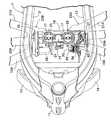
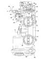
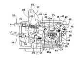
図1〜図10は本発明の一実施例を示すものであり、図1は自動二輪車の要部側面図、図2はエアクリーナを省略した状態での図1の2矢視平面図、図3は吸気制御装置の側面図、図4は図3の4矢視平面図、図5は図3の5矢視底面図、図6は図3の6矢視図、図7は図3の7−7線に沿う切欠き断面図、図8はスロットル操作量センサを省略した状態での図3に対応した側面図、図9は図6の9−9線断面図、図10はスロットル制御系を示すブロック図である。 FIGS. 1 to 10 show an embodiment of the present invention, FIG. 1 is a side view of a main part of a motorcycle, FIG. 2 is a plan view as viewed in the direction of arrow 2 in FIG. 1 with an air cleaner omitted, and FIG. 4 is a side view of the intake control device, FIG. 4 is a plan view taken along the
先ず図1および図2において、鞍乗り型車両である自動二輪車の車体フレームFは、その前端のヘッドパイプ11と、該ヘッドパイプ11から左右に分かれて後下がりに傾斜しつつ後方に延出する左右一対のメインフレーム12…と、両メインフレーム12…の後部に結合されるピボットプレート13…と、前記両メインフレーム12…の下方で左右に分かれて前記ヘッドパイプ11に連設されるとともに前記両メインフレーム12…よりも急角度で後下がりに傾斜したダウンパイプ14…とを備える。 1 and 2, a body frame F of a motorcycle, which is a saddle-ride type vehicle, is divided into a left and
この車体フレームFには、自動二輪車の前後方向に並ぶ3気筒を左右両側にそれぞれ有する6気筒の水平対向型に構成される機関本体15が、前記両メインフレーム12…よりも下方に位置するとともにクランク軸線CCを自動二輪車の前後方向に沿わせるようにして搭載されるものであり、該機関本体15は、前記メインフレーム12…の中間部、前記ピボットプレート13…および前記ダウンパイプ14…で支持される。 In the vehicle body frame F, a six-cylinder horizontally-opposed
前記機関本体15の上方で前記車体フレームFにはエアクリーナ16が搭載されており、このエアクリーナ16および前記機関本体15間に、車体フレームFの左右方向に並ぶ一対の吸気路17,17を形成する吸気路形成体18が配置される。この吸気路形成体18の上部は、前記両吸気路17…の上流端を前記エアクリーナ16内の浄化室(図示せず)内に連通させるようにして前記エアクリーナ16の下部に接続される。また吸気路形成体18の下部には、前記両吸気路17…の一方の下流端に共通に通じる3本の吸気管19A,20A,21Aを有する吸気マニホールド22Aと、前記両吸気路17…の他方の下流端に共通に通じる3本の吸気管19B,20B,21Bを有する吸気マニホールド22Bとが接続されており、それらの吸気マニホールド22A,22Bが備える各吸気管19A〜21A,19B〜21Bは、前記機関本体15が備える左右のシリンダヘッド23…に接続される。 An
図3〜図7を併せて参照して、前記吸気路形成体18には、前記両吸気路17,17を横切って車体フレームFの左右方向に延びる弁軸24が回動可能に支承されており、両吸気路17…の開度を制御するバタフライ形のスロットル弁25,25が前記弁軸24に固定される。 Referring also to FIGS. 3 to 7, a
しかも弁軸24の一端部には該弁軸24を回動駆動するアクチュエータ26が連結され、自動二輪車のライダーが図示しない操向ハンドルに装着されたスロットルグリップを回動操作したときの回動操作量すなわちスロットル操作量を検出するスロットル操作量セン
サ27が、吸気路形成体18に支持されて弁軸24の他端に連結される。In addition, an
図7に特に注目して、前記アクチュエータ26は、弁軸24の軸線と平行な回転軸線を有する電動モータ28と、該電動モータ28の回転動力を減速して前記弁軸24の一端部に伝動する減速ギヤ機構29とを備え、電動モータ28は、前記弁軸24の軸線と平行にして吸気路形成体18に設けられる収納凹部30に収納、支持される。その収納凹部30は、一方の吸気路17の側方で吸気路形成体18に一体に形成した膨出部に設けられる。また吸気路形成体18には前記アクチュエータ26を覆うカバー33が取付けられており、このカバー33内には、スロットル弁25…の開度すなわち弁軸24の回動位置を検出するスロットル開度センサ34が前記弁軸24の一端に連結されるようにして収納される。 With particular attention to FIG. 7, the
前記減速ギヤ機構29は、図7から明らかなように、電動モータ28の回転動力を二段階に減速して弁軸24に伝動すべく、互いに軸方向に隣接配置された2つのギヤ列を備えており、その一段目のギヤ列の被動側ギヤの外周側方に前記スロットル開度センサ34が配置される。 As is apparent from FIG. 7, the
ところで、前記電動モータ28は、図2で明示するように、自動二輪車を上方から見た上面視では車体フレームFにおける両メインフレーム12…間に配置されるとともに、自動二輪車の前後方向に沿って前記弁軸24よりも前方に配置される。また機関本体15は、そのクランク軸線CCを自動二輪車の前後方向に沿わせた姿勢で車体フレームFに搭載されるのであるが、自動二輪車を側方から見た側面視で、クランク軸線CCと略平行にして機関本体15の上方に配置される仮想直線SL上に前記弁軸24の軸線C1および前記電動モータ28の回転軸線C2が配置される。 Incidentally, as clearly shown in FIG. 2, the
図8を併せて参照して、弁軸24の他端部にはスロットルドラム35が相対回動を可能として装着され、該スロットルドラム35を覆うようにして吸気路形成体18に複数のねじ部材36…で締結される支持枠37に、前記弁軸24と同軸の回転軸線を有するスロットル操作量センサ27が取付けられる。而してスロットル操作量センサ27は前記弁軸24と同軸にしてスロットルドラム35側に突出する検出軸38を有しており、この検出軸38の先端部には該検出軸38の半径方向に延びる検出アーム39が固定される。一方、前記弁軸24の軸線C1からオフセットした位置で前記スロットルドラム35には、前記弁軸24の周方向に沿う両側から前記検出アーム39の先端部を挟む一対の係合部40a,40aを有する係合アーム40が固着される。すなわちスロットルドラム35が弁軸24の軸線C1まわりに回動すると、係合アーム40および検出アーム39を介して検出軸38が回動することになり、スロットル操作量センサ27が、スロットルドラム35の回動量すなわちスロットル操作量を検出することになる。 Referring also to FIG. 8, a
しかも前記スロットル操作量センサ27および前記アクチュエータ26は、自動二輪車を側方から見た側面視で、車体フレームFの両メインフレーム12…および機関本体15間に配置される。 Moreover, the throttle
また前記弁軸24の軸線C1からオフセットした位置で前記スロットルドラム35には、前記スロットル操作量センサ27側に突出する当接突部41が突設される。一方、スロットルドラム35およびスロットル操作量センサ27間で前記弁軸24の他端には、弁軸24の半径方向に延びる当接アーム42の基端部が固定されており、この当接アーム42の先端部には、前記当接突部41を当接させ得るねじ部材43が進退位置を調節可能として螺合される。しかも前記当接アーム42は、弁軸24に対してスロットルドラム35が図8の矢印で示す閉じ方向44に相対回動するのに応じて前記当接突部41を前記ねじ部材43に当接させるようにして弁軸24に固定されている。 In addition, a
またスロットルドラム35および吸気路形成体18間には、捩じりばねである戻しばね46(図7参照)が設けられており、この戻しばね46によって前記スロットルドラム35は、閉じ方向に回動付勢される。 A return spring 46 (see FIG. 7), which is a torsion spring, is provided between the
さらにスロットルドラム35には、その外周から半径方向外方に突出する規制突部47が突設されており、吸気路形成体18には、前記閉じ方向44へのスロットルドラム35の回動端で前記規制突部47に当接する規制用ねじ部材48が、前記吸気路形成体18に設けられる支持部49に進退位置を調節可能として螺合される。而してスロットルドラム35が、その規制突部47を前記規制用ねじ部材48に当接させた閉じ方向44への回動端に在り、前記弁軸24がスロットル弁25…を閉じ状態とした回動端にあるときに、前記当接突部41および前記ねじ部材43間には、図8で示すように多少の間隙が生じている。 Further, the
前記スロットルドラム35には、図示しない操向ハンドルに装着されたスロットルグリップを開き側に回動するのに応じて牽引される開き側スロットルケーブル52と、前記スロットルグリップを閉じ側に回動するのに応じて牽引される閉じ側スロットルケーブル56とが連結される。開き側スロットルケーブル52および閉じ側スロットルケーブル56は、アウターケーブル53,57内にインナーケーブル54,58が移動可能に挿通されて成るプッシュプルケーブルである。 The
開き側スロットルケーブル52におけるアウターケーブル53の一端から引き出されたインナーケーブル54は、その一端に設けられた係合駒55をスロットルドラム35に係合しつつスロットルドラム35の外周に巻き掛けられるのであるが、その巻き掛け方向は、牽引時にスロットルドラム35を図8の矢印で示す開き方向45に回動駆動する方向に設定される。また閉じ側スロットルケーブル56におけるアウターケーブル57の一端から引き出されたインナーケーブル58は、その一端に設けられた係合駒59をスロットルドラム35に係合しつつスロットルドラム35の外周に巻き掛けられるのであるが、その巻き掛け方向は、牽引時にスロットルドラム35を前記閉じ方向44に回動駆動する方向に設定される。 The
図9を併せて参照して、前記開き側スロットルケーブル52におけるアウターケーブル53の一端は、前記支持枠37に複数のねじ部材61…で締結される固定支持部材62に支持、固定される。一方、閉じ側スロットルケーブル56におけるアウターケーブル57の一端は、前記スロットルドラム35および前記弁軸24の軸線C1と平行な支軸63を介して前記固定支持部材62に回動可能に支承される可動支持部材64に支持、固定される。 Referring also to FIG. 9, one end of the
可動支持部材64の2箇所には、前記支軸63の軸線を中心とする円弧状の長孔65,66が設けられており、それらの長孔65,66にそれぞれ挿通される軸67,68が前記固定支持部材62に固定される。したがって可動支持部材64は、長孔65,66内で前記軸67,68が移動し得る範囲で前記支軸63の軸線まわりに回動可能である。しかも固定支持部材62および可動支持部材64間には、コイル状のばね69が縮設されており、このばね69が発揮するばね荷重によって前記可動支持部材64は、閉じ側スロットルケーブル56におけるアウターケーブル57の一端の前記可動支持部材64への支持、固定部分が、スロットルドラム35から離反する方向に回動付勢される。 Arc-shaped
一方、固定支持部材62には検出軸71を有するキャンセルスイッチ70が固定されており、前記検出軸71に当接し得るねじ部材72が進退位置を調節可能として可動支持部材64に螺合される。而してキャンセルスイッチ70は、前記検出軸71から前記ねじ部
材72が離間したときにスイッチング態様を変化させるものであり、前記ねじ部材72は、前記可動支持部材64が前記ばね69のばね力に抗して回動したときに前記検出軸71から離間する位置で可動支持部材64に螺合される。On the other hand, a cancel
図10において、アクチュエータ26における電動モータ28の作動は制御ユニット75で制御されるものであり、この制御ユニット75には、スロットル開度センサ34、スロットル操作量センサ27、前記キャンセルスイッチ70および車速センサ76からの信号が入力されるとともに、吸気路17…の吸気圧を検出すべく吸気路形成体18の前面に取付けられる吸気圧センサ77、エアクリーナ16内の温度を検出する吸気温センサ78、ならびに自動二輪車のオークルーズ状態および非オートクルーズ状態を切換えるオートクルーズ選択スイッチ79からの信号が入力される。 In FIG. 10, the operation of the
而してオートクルーズ選択スイッチ79が非オートクルーズ状態を選択している状態で、制御ユニット75は、自動二輪車のライダーがスロットルグリップを回動操作するのに応じたスロットルドラム35の回動量がスロットル操作量センサ27から入力されるのに応じて、スロットル操作量に応じたスロットル開度となるように電動モータ28の作動を制御する。 Thus, in a state where the auto-
またオートクルーズ選択スイッチ79がオートクルーズ状態を選択したときに、制御ユニット75は、そのオートクルーズ選択スイッチ79の切換え操作時において車速センサ76で得られた車速を維持するように、吸気圧および吸気温を考慮しつつスロットル開度を制御すべく電動モータ28の作動を制御する。 When the auto
このようなオートクルーズ状態で、スロットルグリップ側からスロットルドラム35に回動力は入力されていないが、弁軸24の他端に設けられる当接アーム42の先端部のねじ部材43と、スロットルドラム35の当接突部41とが当接することにより、スロットルドラム35は弁軸24の回動に追随して回動することになる。すなわちスロットルドラム35は、オートクルーズ状態では弁軸24の回動に追随するように該弁軸24に連動、連結されている。 In such an auto-cruise state, no rotational force is input to the
またスロットルドラム35に前記弁軸24側からの荷重が上述のように作用しているオークルーズ状態で、ライダーがスロットルグリップを戻し側に操作したときには、戻し側スロットルケーブル56のアウターケーブル57には、それを短縮する側の荷重が作用することになり、その反力によって可動支持部材64がばね69のばね力に抗して回動することにより、可動支持部材64のねじ部材72がキャンセルスイッチ70の検出軸71から離間してキャンセルスイッチ70のスイッチング態様が変化し、そのスイッチング態様の変化に応じて制御ユニット75は、オートクルーズ状態を解除することになる。 When the rider operates the throttle grip to the return side in the auto cruise state where the load from the
すなわちオークルーズ状態でスロットルドラム35にライダーが閉じ側の操作力を加えるのに応じてキャンセルスイッチ70がスイッチング態様を変化し、それに応じて制御ユニット75が、オートクルーズ状態を解除することになる。 That is, the cancel
次にこの実施例の作用について説明すると、車体フレームFの左右方向に延びて吸気路形成体18に回動可能に支承される弁軸24の一端に、該弁軸24を回動駆動する動力を発揮し得る電動モータ28を含むアクチュエータ26が連結され、ライダーのスロットル操作量を検出するスロットル操作量センサ27が吸気路形成体18に支持されて弁軸24の他端に連結されるので、スロットル操作量センサ27を吸気路形成体18にユニット化して組付けて組付け性を高めるとともにコンパクト化を図ることが可能であり、しかも車体フレームFの左右方向中央部に吸気路形成体18が配置された状態で、車体フレーム18の左右方向中央部から吸気制御装置の両端までの距離を略等しくすることができる。 Next, the operation of this embodiment will be described. The power for rotating the
また車体フレームFは、その前端のヘッドパイプ11と、該ヘッドパイプ11から左右に分かれて後方に延びる一対のメインフレーム12…とを備え、弁軸24の軸線C1と平行な回転軸線C2を有する前記電動モータ28が、自動二輪車を上方から見た上面視では両メインフレーム12…間に配置されるので、アクチュエータ26の一部を構成する電動モータ28を左右一対のメインフレーム12…で囲んで保護することができる。 Further, the vehicle body frame F includes a
また電動モータ28が自動二輪車の前後方向に沿って弁軸24よりも前方に配置されることにより、自動二輪車の走行風によって電動モータ28を効果的に冷却することができ、熱だれ現象の発生を防止して電動モータ28の作動性を高めることができる。 Further, since the
またライダーのスロットル操作に応じて回動するスロットルドラム35が、前記弁軸24の他端部に相対回動を可能として装着され、弁軸24と同軸であるスロットル操作量センサ27が、スロットルドラム35に連結されつつ該スロットルドラム35に対向して吸気路形成体18に支持されているので、スロットルドラム35およびスロットル操作量センサ27を連結するにあたってリンク機構等の複雑な連結構造が不要であり、スロットルドラム35およびスロットル操作量センサ27を簡単な連結構造で連結することができる。 A
しかも機関本体15が両メインフレーム12…よりも下方に配置されて車体フレームFに搭載され、アクチュエータ26およびスロットル操作量センサ27が自動二輪車を側方から見た側面視で両メインフレーム12…および機関本体15間に配置されるので、吸気制御装置のコンパクト化を図ることができ、また自動二輪車を側方から見たときに両メインフレーム12…および機関本体15間でアクチュエータ26およびスロットル操作量センサ27を視認することができ、アクチュエータ26およびスロットル操作量センサ27の整備性が向上する。 In addition, the
ところで、水平対向型に構成される機関本体15はクランク軸線CCを自動二輪車の前後方向に沿わせた姿勢で車体フレームFに搭載されており、自動二輪車を側方から見た側面視でクランク軸線CCと略平行にして機関本体15の上方に配置される仮想直線SL上に弁軸24の軸線C1および電動モータ28の回転軸線C2が配置されるので、吸気制御装置を機関本体15の上面に近接させて配置することが可能であり、吸気系のコンパクト化が可能となる。 By the way, the
さらにスロットルドラム35は、オートクルーズ状態で弁軸24の回動に追随するように該弁軸24に連動、連結されるものであり、このスロットルドラム35にオートクルーズ状態でライダーが閉じ側の操作力を加えると、キャンセルスイッチ70がスイッチング態様を変化し、それに応じて制御ユニット75がオートクルーズ状態を解除するものであり、オークルーズ状態を解除する構成を簡略化することができる。 Further, the
以上、本発明の実施例を説明したが、本発明は上記実施例に限定されるものではなく、特許請求の範囲に記載された本発明を逸脱することなく種々の設計変更を行うことが可能である。 Although the embodiments of the present invention have been described above, the present invention is not limited to the above-described embodiments, and various design changes can be made without departing from the present invention described in the claims. It is.
たとえば電動モータ28を、自動二輪車の前後方向に沿って弁軸24よりも後方に配置することも可能であり、そうすると、走行風による電動モータ28の冷却効果が薄れるが、吸気路形成体18の前側上方に配置されるエアクリーナ16の容量増加に寄与することができる。 For example, the
また本発明は、自動二輪車だけでなく鞍乗り型車両に関して広く実施することができる
。The present invention can be widely implemented not only for motorcycles but also for saddle riding type vehicles.
11・・・ヘッドパイプ
12・・・メインフレーム
15・・・機関本体
17・・・吸気路
18・・・吸気路形成体
23・・・シリンダヘッド
24・・・弁軸
25・・・スロットル弁
26・・・アクチュエータ
27・・・スロットル操作量センサ
28・・・電動モータ
35・・・スロットルドラム
70・・・キャンセルスイッチ
75・・・制御ユニット
C1・・・弁軸の軸線
C2・・・電動モータの回転軸線
CC・・・クランク軸線
SL・・・仮想直線
F・・・・車体フレームDESCRIPTION OF
Claims (7)
Translated fromJapanese前記弁軸(24)の軸線(C1)と平行な回転軸線(C2)を有して車両上面視で前記一対のメインフレーム(12)間に配置される前記電動モータ(28)が、一部の前記吸気路(17)の側方で前記吸気路形成体(18)に一体に形成した膨出部に設けた収納凹部(30)に収納、支持され、
前記アクチュエータ(26)は、前記電動モータ(28)の回転動力を減速して前記弁軸(24)に伝動する減速ギヤ機構(29)を備えていて、それら減速ギヤ機構(29)及び電動モータ(28)が、前記吸気路形成体(18)とは別体に形成されて該形成体(18)に取付けたカバー(33)により覆われており、
車両運転者のスロットル操作に応じて回動するスロットルドラム(35)が、前記弁軸(24)の端部に相対回動を可能として装着され、
前記吸気路形成体(18)には、前記カバー(33)とは別個独立に構成されて前記スロットルドラム(35)を覆う支持枠(37)が着脱可能に装着されると共に、その支持枠(37)には、前記弁軸(24)と同軸の回転軸線を有して該スロットルドラム(35)に対向配置したスロットル操作量センサ(27)が取付けられ、
前記弁軸(24)の、前記スロットルドラム(35)側の一端より延びるアーム(42)に係合して、前記スロットルドラム(35)の前記弁軸(24)に対する閉じ方向(44)への相対回動を規制可能な突部(41)と、前記スロットル操作量センサ(27)に対し前記弁軸(24)の軸線方向に抜差可能に係合して前記スロットルドラム(35)に前記スロットル操作量センサ(27)を連動させる係合部(40a)とが、前記弁軸の周
方向に互いにオフセットした位置で前記スロットルドラム(35)の支持枠(37)側の一側面に設けられることを特徴とする、鞍乗り型車両における吸気制御装置。The engine body (15) is mounted on a vehicle body frame (F) having a head pipe (11) at the front end and a pair of main frames (12) extending from the head pipe (11) to the left and right. The intake passage forming body (18) connected to the cylinder head (23) of the engine body (15) crosses the plurality of intake passages (17) formed in parallel with the intake passage forming body (18). A valve shaft (24) extending in the left-right direction of the vehicle body frame (F) is rotatably supported. A plurality of butterfly throttle valves (25) arranged in parallel in the axial direction are attached to the valve shaft (24). An actuator (26) including an electric motor (28) that is fixed so as to control the opening degree of the passage (17) and that can exert power for rotationally driving the valve shaft (24) is provided by the valve shaft (24). A saddle riding type In the intake control device in both,
The electric motor (28) having a rotation axis (C2) parallel to the axis (C1) of the valve shaft (24) and disposed between the pair of main frames (12) in a top view of the vehicle is partially Is housed and supported in a housing recess (30) provided in a bulge formed integrally with the air intake passage forming body (18) on the side of the air intake passage (17)
Said actuator (26), said valve shaft by decelerating the rotational power of the electric motor (28)equipped with a reduction gear mechanism for transmitting (24)(29), which reduction gear mechanism (29) and the electric motor (28)is covered with a cover (33) formed separately from the intake passage forming body (18) and attached to the forming body (18),
A throttle drum (35) that rotates according to the throttle operation of the vehicle driver is attached to the end of the valve shaft (24) so as to be relatively rotatable,
A support frame (37), which is configured separately from the cover (33) and covers the throttle drum (35), is detachably mounted on the intake passage forming body (18). 37) is attached with a throttle operation amount sensor (27) having a rotation axis coaxial with the valve shaft (24) and disposed opposite to the throttle drum (35),
The valve shaft (24) is engaged with an arm (42) extending from one end on the throttle drum (35) side, and the throttle drum (35) in the closing direction (44) with respect to the valve shaft (24). A protrusion (41) capable of restricting relative rotation and a throttle operation amount sensor (27) are detachably engaged in the axial direction of the valve shaft (24), and are engaged with the throttle drum (35). An engagement portion (40a) for interlocking the throttle operation amount sensor (27) is connected to the circumference of the valve shaft.
An intake control device for a saddle-ride type vehicle, whichis provided on one side surface of the throttle drum (35) side of the throttle drum (35) at a position offset from each other in the direction.
Priority Applications (3)
| Application Number | Priority Date | Filing Date | Title |
|---|---|---|---|
| JP2005303312AJP4732119B2 (en) | 2005-10-18 | 2005-10-18 | Intake control device for saddle-ride type vehicles |
| EP06018697.0AEP1777396B1 (en) | 2005-10-18 | 2006-09-06 | Intake air control device |
| US11/581,519US7431013B2 (en) | 2005-10-18 | 2006-10-16 | Intake air control device, and vehicle including same |
Applications Claiming Priority (1)
| Application Number | Priority Date | Filing Date | Title |
|---|---|---|---|
| JP2005303312AJP4732119B2 (en) | 2005-10-18 | 2005-10-18 | Intake control device for saddle-ride type vehicles |
Publications (2)
| Publication Number | Publication Date |
|---|---|
| JP2007113416A JP2007113416A (en) | 2007-05-10 |
| JP4732119B2true JP4732119B2 (en) | 2011-07-27 |
Family
ID=37682881
Family Applications (1)
| Application Number | Title | Priority Date | Filing Date |
|---|---|---|---|
| JP2005303312AExpired - Fee RelatedJP4732119B2 (en) | 2005-10-18 | 2005-10-18 | Intake control device for saddle-ride type vehicles |
Country Status (3)
| Country | Link |
|---|---|
| US (1) | US7431013B2 (en) |
| EP (1) | EP1777396B1 (en) |
| JP (1) | JP4732119B2 (en) |
Families Citing this family (18)
| Publication number | Priority date | Publication date | Assignee | Title |
|---|---|---|---|---|
| JP4745258B2 (en)* | 2007-01-29 | 2011-08-10 | 川崎重工業株式会社 | Electronically controlled throttle device and motorcycle |
| JP5053159B2 (en)* | 2007-09-18 | 2012-10-17 | ヤマハ発動機株式会社 | Saddle riding vehicle |
| JP2009154713A (en) | 2007-12-26 | 2009-07-16 | Yamaha Motor Co Ltd | Control device for saddle-ride type vehicle and saddle-ride type vehicle |
| JP5048621B2 (en)* | 2008-09-25 | 2012-10-17 | 株式会社ケーヒン | Control device for vehicle engine |
| JP5372571B2 (en)* | 2009-03-30 | 2013-12-18 | 本田技研工業株式会社 | Motorcycle |
| US9162573B2 (en) | 2010-06-03 | 2015-10-20 | Polaris Industries Inc. | Electronic throttle control |
| US20120240898A1 (en)* | 2011-03-23 | 2012-09-27 | Visteon Global Technologies, Inc. | Integrated plastic throttle body, electronic control unit, and sensors for small engine |
| JP5727828B2 (en)* | 2011-03-23 | 2015-06-03 | 本田技研工業株式会社 | Saddle riding vehicle |
| JP5745301B2 (en)* | 2011-03-25 | 2015-07-08 | 本田技研工業株式会社 | Throttle sensor mounting structure |
| JP5874527B2 (en)* | 2012-05-15 | 2016-03-02 | スズキ株式会社 | Intake control device for motorcycle |
| JP2014025348A (en) | 2012-07-24 | 2014-02-06 | Yamaha Motor Co Ltd | Saddle-type vehicle |
| US9205717B2 (en) | 2012-11-07 | 2015-12-08 | Polaris Industries Inc. | Vehicle having suspension with continuous damping control |
| CN107406094B (en) | 2014-10-31 | 2020-04-14 | 北极星工业有限公司 | System and method for controlling a vehicle |
| CN110121438B (en) | 2016-11-18 | 2023-01-31 | 北极星工业有限公司 | vehicles with adjustable suspension |
| US10406884B2 (en) | 2017-06-09 | 2019-09-10 | Polaris Industries Inc. | Adjustable vehicle suspension system |
| US10987987B2 (en) | 2018-11-21 | 2021-04-27 | Polaris Industries Inc. | Vehicle having adjustable compression and rebound damping |
| US12397878B2 (en) | 2020-05-20 | 2025-08-26 | Polaris Industries Inc. | Systems and methods of adjustable suspensions for off-road recreational vehicles |
| MX2022015902A (en) | 2020-07-17 | 2023-01-24 | Polaris Inc | Adjustable suspensions and vehicle operation for off-road recreational vehicles. |
Family Cites Families (16)
| Publication number | Priority date | Publication date | Assignee | Title |
|---|---|---|---|---|
| JPH0629578B2 (en)* | 1984-02-21 | 1994-04-20 | ヤマハ発動機株式会社 | Synchronous opening / closing device for intake throttle valve of multi-cylinder internal combustion engine in motorcycle |
| JPS616032A (en)* | 1984-06-15 | 1986-01-11 | Honda Motor Co Ltd | Motorcycle constant speed maintenance device |
| JP2645711B2 (en)* | 1987-10-03 | 1997-08-25 | 本田技研工業株式会社 | Exhaust heat supply device for intake system of motorcycle |
| JPH04203431A (en) | 1990-11-30 | 1992-07-24 | Honda Motor Co Ltd | Intake air control for multi-cylinder internal combustion engine |
| JPH07324636A (en)* | 1994-04-04 | 1995-12-12 | Nippondenso Co Ltd | Throttle valve controller |
| JPH09112299A (en)* | 1995-10-12 | 1997-04-28 | Denso Corp | Throttle valve control device |
| JP3795199B2 (en)* | 1997-09-30 | 2006-07-12 | 本田技研工業株式会社 | Low floor motorcycle |
| JP2002256903A (en)* | 2001-03-05 | 2002-09-11 | Yamaha Motor Co Ltd | Throttle control device of motorcycle |
| US7156074B2 (en)* | 2002-10-11 | 2007-01-02 | Mikuni Corporation | Throttle device |
| JP4463488B2 (en)* | 2003-03-27 | 2010-05-19 | 本田技研工業株式会社 | Throttle body |
| JP2004300944A (en)* | 2003-03-28 | 2004-10-28 | Denso Corp | Throttle device for internal combustion engine |
| JP2005042565A (en)* | 2003-07-23 | 2005-02-17 | Suzuki Motor Corp | Throttle valve device |
| JP4093173B2 (en)* | 2003-10-31 | 2008-06-04 | 株式会社デンソー | Throttle control device for internal combustion engine |
| ES2381005T3 (en)* | 2003-11-12 | 2012-05-22 | Yamaha Hatsudoki Kabushiki Kaisha | Electronic butterfly and motorcycle valve control system |
| JP2005147012A (en)* | 2003-11-17 | 2005-06-09 | Aisan Ind Co Ltd | Throttle control device and its manufacturing method |
| US7237528B2 (en)* | 2004-03-26 | 2007-07-03 | Kawasaki Jukogyo Kabushiki Kaisha | Throttle valve control device for leisure vehicle |
- 2005
- 2005-10-18JPJP2005303312Apatent/JP4732119B2/ennot_activeExpired - Fee Related
- 2006
- 2006-09-06EPEP06018697.0Apatent/EP1777396B1/ennot_activeCeased
- 2006-10-16USUS11/581,519patent/US7431013B2/enactiveActive
Also Published As
| Publication number | Publication date |
|---|---|
| US7431013B2 (en) | 2008-10-07 |
| EP1777396A2 (en) | 2007-04-25 |
| JP2007113416A (en) | 2007-05-10 |
| US20070084440A1 (en) | 2007-04-19 |
| EP1777396B1 (en) | 2017-10-25 |
| EP1777396A3 (en) | 2014-11-12 |
Similar Documents
| Publication | Publication Date | Title |
|---|---|---|
| EP1777396B1 (en) | Intake air control device | |
| EP1777150B1 (en) | Saddle type vehicle | |
| EP1777395B1 (en) | Intake air control device | |
| JP4671356B2 (en) | Saddle type vehicle | |
| US8051939B2 (en) | Throttle control apparatus for a vehicle and vehicle incorporating same | |
| JP4732272B2 (en) | Intake system structure of a V-type internal combustion engine for motorcycles | |
| US20080178840A1 (en) | Electronic control throttle system for a vehicle and vehicle equipped therewith | |
| US10029567B2 (en) | Throttle control module and vehicle | |
| JP2006336638A (en) | Straddle type vehicle | |
| US10718424B2 (en) | Motorcycle | |
| US11022211B2 (en) | Vehicle shift control device | |
| JP5215092B2 (en) | Engine and vehicle equipped with this | |
| JP2008088877A (en) | Intake device for V-type internal combustion engine | |
| JP4815252B2 (en) | Constant vehicle speed control device | |
| JP5874527B2 (en) | Intake control device for motorcycle | |
| US20180056772A1 (en) | Tractor | |
| US10953954B2 (en) | Motorcycle | |
| JP2013204512A (en) | Throttle device of engine | |
| JP5129773B2 (en) | Intake control device for vehicle engine | |
| JP2010127199A (en) | Throttle device | |
| JP5102747B2 (en) | Throttle operating device and vehicle equipped with the same | |
| JP4620367B2 (en) | Arrangement structure of fuel injection device in motorcycle | |
| JP4990058B2 (en) | Fuel injection valve mounting structure for small vehicle engine | |
| JP2007138849A (en) | Vehicle mounting internal combustion engine equipped with idling speed control system |
Legal Events
| Date | Code | Title | Description |
|---|---|---|---|
| A621 | Written request for application examination | Free format text:JAPANESE INTERMEDIATE CODE: A621 Effective date:20071127 | |
| A977 | Report on retrieval | Free format text:JAPANESE INTERMEDIATE CODE: A971007 Effective date:20090629 | |
| A131 | Notification of reasons for refusal | Free format text:JAPANESE INTERMEDIATE CODE: A131 Effective date:20090701 | |
| A521 | Request for written amendment filed | Free format text:JAPANESE INTERMEDIATE CODE: A523 Effective date:20090831 | |
| A02 | Decision of refusal | Free format text:JAPANESE INTERMEDIATE CODE: A02 Effective date:20100106 | |
| A521 | Request for written amendment filed | Free format text:JAPANESE INTERMEDIATE CODE: A523 Effective date:20100405 | |
| A911 | Transfer to examiner for re-examination before appeal (zenchi) | Free format text:JAPANESE INTERMEDIATE CODE: A911 Effective date:20100408 | |
| A912 | Re-examination (zenchi) completed and case transferred to appeal board | Free format text:JAPANESE INTERMEDIATE CODE: A912 Effective date:20100604 | |
| A01 | Written decision to grant a patent or to grant a registration (utility model) | Free format text:JAPANESE INTERMEDIATE CODE: A01 | |
| A61 | First payment of annual fees (during grant procedure) | Free format text:JAPANESE INTERMEDIATE CODE: A61 Effective date:20110420 | |
| FPAY | Renewal fee payment (event date is renewal date of database) | Free format text:PAYMENT UNTIL: 20140428 Year of fee payment:3 | |
| R150 | Certificate of patent or registration of utility model | Ref document number:4732119 Country of ref document:JP Free format text:JAPANESE INTERMEDIATE CODE: R150 Free format text:JAPANESE INTERMEDIATE CODE: R150 | |
| LAPS | Cancellation because of no payment of annual fees |