Movatterモバイル変換


[0]ホーム

URL:


JP4732015B2 - Concentrating solar power generation unit and concentrating solar power generation device - Google Patents

Concentrating solar power generation unit and concentrating solar power generation device
Download PDF

Info

Publication number
JP4732015B2
JP4732015B2JP2005167526AJP2005167526AJP4732015B2JP 4732015 B2JP4732015 B2JP 4732015B2JP 2005167526 AJP2005167526 AJP 2005167526AJP 2005167526 AJP2005167526 AJP 2005167526AJP 4732015 B2JP4732015 B2JP 4732015B2
Authority
JP
Japan
Prior art keywords
power generation
solar power
solar cell
plate
frame
Prior art date
Legal status (The legal status is an assumption and is not a legal conclusion. Google has not performed a legal analysis and makes no representation as to the accuracy of the status listed.)
Expired - Fee Related
Application number
JP2005167526A
Other languages
Japanese (ja)
Other versions
JP2006344698A (en
Inventor
修 安沢
正雄 田中
Current Assignee (The listed assignees may be inaccurate. Google has not performed a legal analysis and makes no representation or warranty as to the accuracy of the list.)
Sharp Corp
Original Assignee
Sharp Corp
Priority date (The priority date is an assumption and is not a legal conclusion. Google has not performed a legal analysis and makes no representation as to the accuracy of the date listed.)
Filing date
Publication date
Application filed by Sharp CorpfiledCriticalSharp Corp
Priority to JP2005167526ApriorityCriticalpatent/JP4732015B2/en
Priority to EP06757110Aprioritypatent/EP1895597A1/en
Priority to PCT/JP2006/311403prioritypatent/WO2006132265A1/en
Priority to US11/921,465prioritypatent/US8237044B2/en
Priority to AU2006256136Aprioritypatent/AU2006256136B8/en
Publication of JP2006344698ApublicationCriticalpatent/JP2006344698A/en
Application grantedgrantedCritical
Publication of JP4732015B2publicationCriticalpatent/JP4732015B2/en
Anticipated expirationlegal-statusCritical
Expired - Fee Relatedlegal-statusCriticalCurrent

Links

Images

Classifications

Landscapes

Description

Translated fromJapanese

本発明は、集光レンズを用いて太陽光を集光することにより発電容量を大きくすることが可能な集光型太陽光発電ユニット、およびそのような集光型太陽光発電ユニットを備える集光型太陽光発電装置に関する。  The present invention relates to a concentrating solar power generation unit capable of increasing power generation capacity by concentrating sunlight using a condensing lens, and a condensing unit including such a concentrating solar power generation unit. Type solar power generation apparatus.

太陽エネルギーを電力に変換する太陽光発電装置が実用化されているが、低コスト化を実現し、さらに大電力を得るために、集光レンズで集光した太陽光を集光レンズの受光面積より小さい太陽電池素子に照射して電力を取り出すタイプの集光型太陽光発電装置が実用化されている。  Solar power generation devices that convert solar energy into electric power have been put into practical use, but in order to achieve lower costs and to obtain higher power, the sunlight received by the condensing lens is received by the condensing lens. A concentrating solar power generation apparatus of a type that takes out electric power by irradiating a smaller solar cell element has been put into practical use.

集光型太陽光発電装置は、太陽光を集光レンズで集光することから、太陽電池素子としては、光学系で集光された太陽光を受光できる小さい受光面積を備えれば良い。つまり、集光レンズの受光面積より小さいサイズの太陽電池素子で良いことから、太陽電池素子のサイズを縮小することができ、太陽光発電装置において高価な構成物である太陽電池素子の使用量を減らすことができ、コストを低減することが可能となる。このような利点から、集光型太陽光発電装置は、広大な面積を利用して発電することが可能な地域などで、電力供給用に利用されつつある。  Since the concentrating solar power generation device condenses sunlight with a condensing lens, the solar cell element only needs to have a small light receiving area capable of receiving sunlight condensed by the optical system. In other words, since the solar cell element having a size smaller than the light receiving area of the condenser lens may be used, the size of the solar cell element can be reduced, and the usage amount of the solar cell element, which is an expensive component in the solar power generation device, can be reduced. The cost can be reduced. Due to such advantages, the concentrating solar power generation apparatus is being used for power supply in an area where power can be generated using a large area.

集光型太陽光発電装置として、太陽電池モジュールを支持板に取り付けるという簡単な構成により、重量の増大を招くことなく充分な強度、剛性が得られ、充分な放熱性が得られるようにしたものが提案されている(例えば特許文献1参照。)。
特開平11−284217号公報
As a concentrating solar power generation device, a simple structure in which a solar cell module is attached to a support plate provides sufficient strength and rigidity without increasing weight, and sufficient heat dissipation. Has been proposed (see, for example, Patent Document 1).
Japanese Patent Laid-Open No. 11-284217

しかし、集光型太陽光発電装置の集光レンズは、太陽電池素子に対して適正な位置関係に配置されなければならず、高度な位置合わせが要求される。さらに、受光位置での集光によるエネルギーは極めて大きく、太陽電池素子周辺への照射による損傷防止対策などが放熱対策として必要である。  However, the condensing lens of the concentrating solar power generation apparatus must be disposed in an appropriate positional relationship with respect to the solar cell element, and high-level alignment is required. Furthermore, the energy by condensing at the light receiving position is extremely large, and measures for preventing damage due to irradiation around the solar cell element are necessary as measures for heat dissipation.

また、集光型太陽光発電装置は、砂漠等の温度変化の激しい地域に設置されることもしばしばであり、温度上昇に対する熱膨張対策も必要である。  In addition, the concentrating solar power generation apparatus is often installed in a region such as a desert where the temperature change is severe, and it is necessary to take measures against thermal expansion against a temperature rise.

すなわち、確実に太陽光から電力を取り出す太陽光発電装置とするために、太陽電池素子の実装、太陽電池素子と光学系との間の位置関係の調整などにおいて、熱、集光に対する適切な対策を施すことが極めて重要である。  In other words, in order to obtain a solar power generation device that reliably extracts power from sunlight, appropriate measures against heat and light collection in the mounting of solar cell elements, adjustment of the positional relationship between the solar cell elements and the optical system, etc. Is very important.

本発明はこのような状況に鑑みてなされたものであり、太陽電池素子を実装する実装板と、太陽光を透過させる透過穴を有し実装板を覆う遮光板と、太陽電池素子の受光領域に太陽光を集光する集光レンズと、太陽電池素子と集光レンズとの位置を合わせるフレームとを備えることにより、組み立てが容易で生産性および保守(維持・点検)の作業性を向上させ、光学部材の位置合わせが容易で、熱、太陽光に対して優れた作用を生じる集光型太陽光発電ユニットおよび集光型太陽光発電装置を提供することを目的とする。  The present invention has been made in view of such a situation, a mounting plate for mounting a solar cell element, a light shielding plate having a transmission hole that transmits sunlight, and covering the mounting plate, and a light receiving region of the solar cell element With a condensing lens that condenses sunlight and a frame that aligns the position of the solar cell element and the condensing lens, making assembly easy and improving productivity and maintenance (maintenance / inspection) workability It is an object of the present invention to provide a concentrating solar power generation unit and a concentrating solar power generation device that can easily align optical members and produce excellent effects on heat and sunlight.

本発明に係る集光型太陽光発電ユニットは、集光レンズで集光した太陽光を太陽電池素子に照射して発電する集光型太陽光発電ユニットにおいて、前記太陽電池素子を実装してある実装板と、前記太陽電池素子の受光領域に太陽光を照射させる透過穴を有し前記実装板を覆う遮光板と、該遮光板に対向して配置され前記受光領域に太陽光を集光する集光レンズと、前記太陽電池素子と前記集光レンズとの位置を合わせて保持するフレームとを備え、前記遮光板と前記フレームとは一体の金属板で形成された構造体とされ、前記遮光板は前記構造体の底部を構成し、前記フレームは前記構造体の側壁を構成し、前記実装板は、前記遮光板に装着されて長手方向の端辺の略中央が前記遮光板に固定されていることを特徴とする。A concentrating solar power generation unit according to the present invention is a concentrating solar power generation unit that generates power by irradiating solar cell elements with sunlight condensed by a condensing lens, wherein the solar cell elements are mounted. A mounting plate, a light shielding plate that has a transmission hole for irradiating sunlight to the light receiving region of the solar cell element, covers the mounting plate, and is disposed opposite to the light shielding plate to collect sunlight in the light receiving region. A light collecting plate, and a frame that holds the solar cell element and the light collecting lens in alignment with each other, wherein the light shielding plate and the frame are a structure formed of an integral metal plate, and the light shielding The plate constitutes the bottom of the structure, the frame constitutes the side wall of the structure, the mounting plate is mounted on the light shielding plate, and the approximate center of the end in the longitudinal direction is fixed to the light shielding plate. It is characterized by.

好ましくは、前記遮光板は、前記透過穴の周縁を前記実装板側に折り曲げた屈曲部を有することを特徴とする。  Preferably, the light shielding plate has a bent portion in which a peripheral edge of the transmission hole is bent toward the mounting plate.

好ましくは、前記実装板は、前記太陽電池素子を複数配置してあることを特徴とする。  Preferably, the mounting board is provided with a plurality of the solar cell elements.

好ましくは、前記集光レンズは、前記複数の太陽電池素子それぞれに対応して透光性保護板に配置され保持されていることを特徴とする。  Preferably, the condensing lens is arranged and held on a translucent protective plate corresponding to each of the plurality of solar cell elements.

好ましくは、前記透光性保護板は長手方向の端辺の略中央を前記フレームの上端に固定してあることを特徴とする。  Preferably, the translucent protective plate is characterized in that the approximate center of the end in the longitudinal direction is fixed to the upper end of the frame.

好ましくは、前記実装板および前記透光性保護板は、前記フレームの長手方向で複数に分割してあることを特徴とする。  Preferably, the mounting plate and the translucent protective plate are divided into a plurality in the longitudinal direction of the frame.

本発明に係る集光型太陽光発電装置は、集光型太陽光発電ユニットを備える集光型太陽光発電装置において、前記集光型太陽光発電ユニットは、本発明に係る集光型太陽光発電ユニットであり、追尾駆動される構成としてあることを特徴とする。  A concentrating solar power generation device according to the present invention is a concentrating solar power generation device including a concentrating solar power generation unit, wherein the concentrating solar power generation unit is a concentrating solar power generation device according to the present invention. The power generation unit is configured to be driven to be tracked.

本発明に係る集光型太陽光発電ユニットおよび集光型太陽光発電装置によれば、太陽電池素子を実装した実装板および太陽電池素子を覆う遮光板と、太陽電池素子および集光レンズの位置関係を画定するフレームとを備える構成としてあり、実装板とフレームとを別構成としてあることから、実装板への太陽電池素子の実装などでの生産性が向上し、保守・点検が容易になり、作業性、信頼性を高めることができるという効果を奏する。
また、遮光板とフレームとを一体の金属板で形成した構造体とすることから、集光型太陽光発電ユニットの構造体(構造骨格)の強度を確実に向上することができる。
According to the concentrating solar power generation unit and the concentrating solar power generation device according to the present invention, the mounting plate on which the solar cell element is mounted, the light shielding plate that covers the solar cell element, the position of the solar cell element and the condensing lens Since the mounting board and the frame are configured separately, the productivity for mounting solar cell elements on the mounting board is improved, and maintenance and inspection are facilitated. There is an effect that workability and reliability can be improved.
Moreover, since the light shielding plate and the frame are made of a single metal plate, the strength of the structure (structural skeleton) of the concentrating solar power generation unit can be reliably improved.

また、構造体(フレーム、遮光板)を基準形状として透過穴に対する実装板、透光性保護板(集光レンズ)の位置合わせを行うことができるので、光学部材(集光レンズ、透光性保護板)と太陽電池素子との位置合わせ精度の確保が容易になる。また、位置合わせ精度を向上できることから、照射される太陽光の利用効率を大きくすることができるという効果を奏する。  In addition, since the structure (frame, light-shielding plate) is used as a reference shape, the mounting plate and the translucent protective plate (condensing lens) can be aligned with the transmission hole, so that the optical member (condensing lens, translucent) It is easy to ensure alignment accuracy between the protective plate and the solar cell element. Moreover, since the alignment accuracy can be improved, there is an effect that the utilization efficiency of the irradiated sunlight can be increased.

また、本発明に係る集光型太陽光発電ユニットおよび集光型太陽光発電装置によれば、太陽電池素子を実装する実装板への太陽光は遮光板で阻止されることから、太陽電池素子を搭載する実装板での損傷を防ぐことができるという効果を奏する。  In addition, according to the concentrating solar power generation unit and the concentrating solar power generation device according to the present invention, the sunlight to the mounting plate on which the solar cell element is mounted is blocked by the light shielding plate. There is an effect that it is possible to prevent damage on the mounting board on which is mounted.

以下、本発明の実施の形態を図面に基づいて説明する。  Hereinafter, embodiments of the present invention will be described with reference to the drawings.

<実施の形態1>
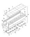
図1は、本発明の実施の形態1に係る集光型太陽光発電ユニットの要部の配置関係を部分的に示す分解斜視図である。図2は、図1の集光型太陽光発電ユニットの実装板とフレーム底部との位置決め・固定の状態を説明する説明図であり、(A)は実装板の斜視図、(B)は位置決め固定状態を示す断面図、(C)は緩い固定状態を示す断面図である。図3は、図1の集光型太陽光発電ユニットの透光性保護板とフレーム上端との位置決め・固定の状態を説明する説明図であり、(A)は透光性保護板などの斜視図、(B)は位置決め固定状態を示す断面図、(C)は緩い固定状態を示す断面図である。
<Embodiment 1>
FIG. 1 is an exploded perspective view partially showing an arrangement relationship of main parts of a concentrating solar power generation unit according toEmbodiment 1 of the present invention. 2A and 2B are explanatory views for explaining the positioning / fixing state between the mounting plate and the bottom of the frame of the concentrating solar power generation unit of FIG. 1, wherein FIG. 2A is a perspective view of the mounting plate, and FIG. Sectional drawing which shows a fixed state, (C) is sectional drawing which shows a loose fixing state. FIG. 3 is an explanatory view for explaining the positioning / fixing state between the translucent protective plate and the upper end of the frame of the concentrating solar power generation unit of FIG. 1, and (A) is a perspective view of the translucent protective plate and the like. FIG. 4B is a cross-sectional view showing a positioning and fixing state, and FIG. 4C is a cross-sectional view showing a loose fixing state.

本実施の形態の集光型太陽光発電ユニット10は、太陽電池素子1、レシーバ2に接着された太陽電池素子1を実装してある実装板3、実装板3を覆う遮光板4、遮光板4の対向する2辺の端部から垂直方向に配置されたフレーム5、遮光板4に対向してフレーム5の上端に対応して配置され太陽電池素子1の受光領域に太陽光Lsを集光する集光レンズ7、集光レンズ7を固定(固着)してフレーム5の上端に装着される透光性保護板6を備える。  The concentrating solarpower generation unit 10 according to the present embodiment includes asolar cell element 1, amounting plate 3 on which thesolar cell element 1 bonded to thereceiver 2 is mounted, alight shielding plate 4 that covers themounting plate 3, and a light shielding plate. The sunlight is focused on the light receiving region of thesolar cell element 1 which is arranged in correspondence with the upper end of theframe 5 facing thelight shielding plate 4 and theframe 5 arranged in the vertical direction from the ends of the two opposite sides of 4. Acondensing lens 7 and a translucentprotective plate 6 fixed to (fixed to) thecondensing lens 7 and attached to the upper end of theframe 5.

機能に対応した構成部材として部品点数を少なくしてあることから、組み立てが容易で、小型・軽量化が可能となり、機械的強度の大きい集光型太陽光発電ユニット10とすることができる。つまり、機能に対応した部材構成となり簡略化した構造となることから、機械的強度および生産性を向上させることができる。また、機械的強度の強いフレーム5により光学的距離を画定することから安定した確実な集光が可能となり、遮光板4により実装板3を覆うことから損傷の恐れのない信頼性の高い発電が可能となる。  Since the number of parts is reduced as a constituent member corresponding to the function, assembly is easy, the size and weight can be reduced, and the concentrating solarpower generation unit 10 having high mechanical strength can be obtained. That is, since the member configuration corresponding to the function is obtained and the structure is simplified, mechanical strength and productivity can be improved. In addition, since the optical distance is defined by theframe 5 having high mechanical strength, stable and reliable light collection is possible, and since themounting plate 3 is covered by thelight shielding plate 4, highly reliable power generation with no risk of damage is achieved. It becomes possible.

実装板3には、レシーバ2に搭載された太陽電池素子1が例えば5個ずつ2列に計10個配置してある。太陽電池素子1は、集光レンズ7の集光位置に対応して配置される。実装板3は、太陽電池素子1、レシーバ2を10個単位として収納する空間を確保する窪みを持つ皿状に形成され、周縁には遮光板4へ取り付けるための鍔3aが形成してある。  For example, a total of tensolar cell elements 1 mounted on thereceiver 2 are arranged on themounting board 3 in two rows of five each. Thesolar cell element 1 is arranged corresponding to the condensing position of thecondensing lens 7. Themounting plate 3 is formed in a dish shape having a recess that secures a space for storing thesolar cell element 1 and thereceiver 2 in units of ten, and aflange 3 a for attaching to thelight shielding plate 4 is formed at the periphery.

実装板3は、放熱性、軽量化などを考慮して例えばアルミニウムで形成することが望ましい。アルミニウムについてはアルマイト加工などの、適当な絶縁処理が施されていても良い。また、実装板3は、遮光板4に装着され、遮光板4と共に10個の太陽電池素子1を収納し、外部環境から保護する保護空間を形成する。  Themounting board 3 is preferably formed of, for example, aluminum in consideration of heat dissipation and weight reduction. The aluminum may be subjected to an appropriate insulation treatment such as anodizing. Themounting plate 3 is attached to thelight shielding plate 4 and houses the tensolar cell elements 1 together with thelight shielding plate 4 to form a protective space for protection from the external environment.

集光レンズ7は、10個の太陽電池素子1のそれぞれに対応するように5個ずつ2列に計10個が透光性保護板6に配置、固定されレンズアレイ(6、7)を構成している。集光レンズ7は加工性、透光性などを考慮して例えばアクリル樹脂で形成してある。なお、レンズ材料としては、ポリカーボネート、ガラスでもよい。  A total of 10condenser lenses 7 are arranged and fixed on the translucentprotective plate 6 in two rows so as to correspond to each of the tensolar cell elements 1 to constitute a lens array (6, 7). is doing. Thecondensing lens 7 is made of, for example, an acrylic resin in consideration of processability and translucency. The lens material may be polycarbonate or glass.

透光性保護板6は、透光性、強度、耐環境性などを考慮して例えばガラスで形成してあり、周囲環境からの風雨の影響を防止することができる。集光レンズ7は、透光性を有する適宜の接着剤で透光性保護板6に接着され保持されている。なお、透光性保護板6の材料としては、アクリル樹脂や、ポリカーボネートでもよい。  The translucentprotective plate 6 is made of, for example, glass in consideration of translucency, strength, environmental resistance, and the like, and can prevent the influence of wind and rain from the surrounding environment. The condensinglens 7 is bonded and held on the translucentprotective plate 6 with an appropriate translucent adhesive. In addition, as a material of thetranslucent protection board 6, an acrylic resin and a polycarbonate may be sufficient.

集光レンズ7は、太陽電池素子1の受光領域に集光するように光学的距離(焦点距離に基づいて規定される)を調整してあることから、集光レンズ7により集光された太陽光Lsは、太陽電池素子1の配置面で極めて大きなエネルギーとなる。また、太陽光Lsを追尾する構成とした場合に、集光された太陽光Lsに太陽電池素子1が常に正対する関係を維持できるとは限らず、さらに、異常事態の発生によって追尾装置が停止する事態も想定される。つまり、集光した太陽光Lsが、太陽電池素子1の受光領域ではなく、受光領域以外の実装板3の周囲部材もしくは実装板3に照射される恐れがあり、そのような場合、照射部分が焼損などにより損傷する恐れがある。  Since the condensinglens 7 is adjusted in optical distance (defined based on the focal length) so as to condense in the light receiving region of thesolar cell element 1, the sun condensed by the condensinglens 7. The light Ls becomes extremely large energy on the arrangement surface of thesolar cell element 1. Moreover, when it is set as the structure which tracks sunlight Ls, thesolar cell element 1 may not always be able to maintain the relationship where it always opposes the condensed sunlight Ls, and also a tracking apparatus stops by generation | occurrence | production of an abnormal condition. It is also assumed that That is, the condensed sunlight Ls may be irradiated not on the light receiving area of thesolar cell element 1 but on the peripheral member of the mountingboard 3 or the mountingboard 3 other than the light receiving area. There is a risk of damage from burning.

したがって、遮光板4は、集光された太陽光Lsによる損傷の発生を防止するように太陽光Lsを遮光する構造としてあり、太陽電池素子1の受光領域以外には太陽光Lsが影響しないように構成してある。また、遮光機能に併せて太陽電池素子1での受光を可能にするため、集光した太陽光Lsを透過させて太陽電池素子1の受光領域に照射する透過穴4aを太陽電池素子1の受光領域に対向させるように位置合わせして設けてある。  Therefore, thelight shielding plate 4 has a structure for shielding the sunlight Ls so as to prevent the occurrence of damage due to the concentrated sunlight Ls, and the sunlight Ls does not affect the light receiving area other than the light receiving region of thesolar cell element 1. It is configured. In addition, in order to enable thesolar cell element 1 to receive light in conjunction with the light shielding function, thesolar cell element 1 receives thetransmission hole 4a that transmits the concentrated sunlight Ls and irradiates the light receiving region of thesolar cell element 1. Positioning is provided so as to face the region.

つまり、実装板3に実装された10個の太陽電池素子1のそれぞれに対応して透過穴4aが穿設してあり、透過穴4aの位置に太陽電池素素子1の位置および集光レンズ7の集光位置を整合させることが発電効率を確保するために極めて重要である。また、遮光板4は、透過穴4aの作用を確実に実現するために、実装板3と近接してフレーム5の底部に対応して配置される。  That is, thetransmission hole 4a is formed corresponding to each of the tensolar cell elements 1 mounted on the mountingplate 3, and the position of thesolar cell element 1 and thecondenser lens 7 are formed at the position of thetransmission hole 4a. In order to ensure power generation efficiency, it is extremely important to align the light condensing positions. Further, thelight shielding plate 4 is disposed in the vicinity of the mountingplate 3 and corresponding to the bottom of theframe 5 in order to reliably realize the function of thetransmission hole 4a.

集光型太陽光発電ユニット10の機械的強度を確保、向上するため、また、生産性を向上するために、フレーム5は連続成形により一体として形成することが好ましい。また、対向する2つのフレーム5の中間に位置する遮光板4もフレーム5と一体であることが好ましい。そのために、遮光板4およびフレーム5は、例えば鉄板、鋼板などの金属板をロールフォーミング加工することにより一体に形成してある。なお、鉄板、鋼板については亜鉛メッキなどの防錆処理が施されていることが望ましい。  In order to ensure and improve the mechanical strength of the concentrating solarpower generation unit 10, and to improve productivity, theframe 5 is preferably formed integrally by continuous molding. Further, it is preferable that thelight shielding plate 4 positioned in the middle of the twoopposed frames 5 is also integral with theframe 5. Therefore, thelight shielding plate 4 and theframe 5 are integrally formed by roll forming a metal plate such as an iron plate or a steel plate. In addition, about an iron plate and a steel plate, it is desirable that rust prevention processing, such as galvanization, is given.

したがって、遮光板4は集光型太陽光発電ユニット10の構造体11の底部を、フレーム5は構造体11の側壁をそれぞれ構成することとなり、集光型太陽光発電ユニット10の構造体(構造骨格)11の強度を確実に向上することができる。  Therefore, thelight shielding plate 4 constitutes the bottom of thestructure 11 of the concentrating solarpower generation unit 10, and theframe 5 constitutes the side wall of thestructure 11. The strength of theskeleton 11 can be reliably improved.

遮光板4をフレーム5と一体とすることにより、遮光板4として別部材を用いる必要がなく生産性を向上することができる。また、遮光板4(透過穴4a)の位置が画定されることから、集光レンズ7に対する実装板3の位置合わせを精度良く行うことができる。  By integrating thelight shielding plate 4 with theframe 5, it is not necessary to use another member as thelight shielding plate 4, and productivity can be improved. Further, since the position of the light shielding plate 4 (transmission hole 4a) is demarcated, the mountingplate 3 can be accurately aligned with thecondenser lens 7.

ロールフォーミング加工時にフレーム5と一体に形成された遮光板4は、実装板3を装着するためにフレーム5の上端側に凸状とされたフレーム底部4bを構成する。以下、フレーム5と一体化して形成された遮光板4を便宜上フレーム底部4bと記載することがある。  Thelight shielding plate 4 formed integrally with theframe 5 at the time of the roll forming process constitutes aframe bottom portion 4 b that is convex on the upper end side of theframe 5 in order to mount the mountingplate 3. Hereinafter, thelight shielding plate 4 formed integrally with theframe 5 may be referred to as aframe bottom 4b for convenience.

つづいて、透過穴4aの位置に太陽電池素素子1の位置を整合させる具体的な構造について説明する。フレーム底部4bに実装板用突起部4dを設け、実装板用突起部4dに対応する実装板位置合わせ部3bを実装板3(鍔3a)に形成することにより(図2(A)参照)、太陽光Lsと交差する方向での実装板3の位置決めが容易に行える。つまり、フレーム底部4bの実装板用突起部4dと実装板3の実装板位置合わせ部3bを嵌合し、ビス30などで固定する(図2(B)参照)。本実施の形態では実装板3の長手方向で対向する2つの端辺(鍔3a)の略中央に実装板位置合わせ部3bをそれぞれ設けて、フレーム底部4bに実装板3を固定している。  Next, a specific structure for aligning the position of thesolar cell element 1 with the position of thetransmission hole 4a will be described. By providing a mountingplate projection 4d on theframe bottom 4b and forming a mountingplate alignment portion 3b corresponding to the mountingplate projection 4d on the mounting plate 3 (鍔 3a) (see FIG. 2A), The mountingboard 3 can be easily positioned in the direction intersecting with the sunlight Ls. That is, the mountingplate protrusion 4d on theframe bottom 4b and the mountingplate alignment portion 3b on the mountingplate 3 are fitted and fixed withscrews 30 or the like (see FIG. 2B). In the present embodiment, a mountingplate alignment portion 3b is provided at substantially the center of two end sides (ridges 3a) facing each other in the longitudinal direction of the mountingplate 3, and the mountingplate 3 is fixed to theframe bottom portion 4b.

さらに、フレーム底部4bに実装板用突起部4dとは別に実装板用突起部4eを設け、実装板用突起部4eに対応する嵌合部3cを実装板3(鍔3a)に形成することにより(図2(A)参照)、実装板3をフレーム底部4bに緩やかに固定することができる。つまり、フレーム底部4bの実装板用突起部4eと実装板3の嵌合部3cとの間のスペースSを介して実装板用突起部4eと嵌合部3cを嵌合し、ビス30などで固定する(図2(C)参照)。なお、フレーム底部4bと実装板3との間には緩衝材33を挟み込んでおいても構わない。  Further, by providing a mountingplate projection 4e separately from the mountingplate projection 4d on theframe bottom 4b, and forming afitting portion 3c corresponding to the mountingplate projection 4e on the mounting plate 3 (鍔 3a). (See FIG. 2A), the mountingplate 3 can be loosely fixed to theframe bottom 4b. That is, the mountingplate projection 4e and thefitting portion 3c are fitted via the space S between the mountingplate projection 4e of theframe bottom 4b and thefitting portion 3c of the mountingplate 3, and thescrew 30 or the like. Fix (see FIG. 2C). Thebuffer material 33 may be sandwiched between theframe bottom 4b and the mountingboard 3.

また、フレーム底部4bに設けた実装板用突起部4d、4eが凹部で、実装板位置合わせ部3b、嵌合部3cが凸部でも構わず、位置決め、固定を行えるものであれば形状は問わない。  Further, the mountingplate projections 4d and 4e provided on theframe bottom 4b may be concave portions, and the mountingplate alignment portion 3b and thefitting portion 3c may be convex portions. Absent.

つづいて、透過穴4aの位置に集光レンズ7の集光位置を整合させる具体的な構造について説明する。フレーム5の上端には、透光性保護板6(集光レンズ7)を支持するための鍔5aがロールフォーミング加工時に一体に形成してあり、集光レンズ7の位置決めを確実に行うことが可能となる。  Next, a specific structure for aligning the condensing position of the condensinglens 7 with the position of thetransmission hole 4a will be described. Aflange 5a for supporting the translucent protective plate 6 (condensing lens 7) is integrally formed at the upper end of theframe 5 at the time of roll forming, so that the condensinglens 7 can be positioned reliably. It becomes possible.

また、フレーム5の鍔5aに鍔突起部5cを設け(図1参照)、鍔突起部5cに対応する保護板枠位置合わせ部6bを透光性保護板6の長手方向の端辺(枠部6a)の略中央に形成することにより(図3(A)参照)、太陽光Lsと交差する方向での透光性保護板6(集光レンズ7)の位置決めが容易に行える。なお、鍔5aに設けた鍔突起部5cは、凹部でも構わず、位置決めを行えるものであれば形状は問わない。  Further, theflange 5a of theframe 5 is provided with aflange projection 5c (see FIG. 1), and the protective plateframe alignment portion 6b corresponding to theflange projection 5c is connected to the longitudinal side edge (frame portion) of thetranslucent protection plate 6. By forming it at the approximate center of 6a) (see FIG. 3A), the translucent protective plate 6 (condensing lens 7) can be easily positioned in the direction intersecting with the sunlight Ls. Thehook protrusion 5c provided on thehook 5a may be a recess, and the shape is not limited as long as it can be positioned.

また、鍔突起部5cを用いずに、保護板枠位置合わせ部6bに常温で硬化するシリコーン系樹脂などを流し込むことで、枠部6aを鍔5aに固定しても構わない。位置決めに際しては太陽電池素子1と集光レンズ7の光学的位置合せを幾何学的測定や発電電力測定などにより行い、透光性保護板6を鍔5aに仮止めした後樹脂にて固定すればよい。  Alternatively, theframe portion 6a may be fixed to theflange 5a by pouring a silicone resin or the like that cures at room temperature into the protective plateframe alignment portion 6b without using theflange protrusion 5c. At the time of positioning, optical alignment between thesolar cell element 1 and thecondenser lens 7 is performed by geometric measurement or generated power measurement, and the light-transmittingprotective plate 6 is temporarily fixed to theflange 5a and then fixed with resin. Good.

透光性保護板6の長手方向で端辺の略中央に保護板枠位置合わせ部6bを近距離の位置に一対形成することにより、回転することなく透光性保護板6(集光レンズ7)の姿勢を固定することができ、また、透光性保護板6は熱膨張によるストレスの少ない状態で鍔5aに固定されることとなる(図3(B)参照)。  By forming a pair of protective plateframe alignment portions 6b at a short distance in the longitudinal center of the translucentprotective plate 6 at a short distance, the translucent protective plate 6 (the condensing lens 7) is rotated without rotation. ), And the translucentprotective plate 6 is fixed to theflange 5a in a state where there is little stress due to thermal expansion (see FIG. 3B).

また、透光性保護板6の枠部6aは押え部材9によって、透光性保護板6が伸縮可能となるように押えることが好ましく、透光性保護板6の端面に緩衝材32を巻き付け、押え部材9を押え穴9aを通るボルト31で鍔5aに固定することで、透光性保護板6の機械的ストレスからの保護と止水機能を持たせることができる。つまり、透光性保護板6は保護板枠位置合わせ部6bのみで固定され、押え部材9により緩やかに押えられた状態となることから、熱膨張などによる伸縮のストレスがかからないこととなる(図3(C)参照)。  Further, theframe portion 6 a of the translucentprotective plate 6 is preferably pressed by the pressingmember 9 so that the translucentprotective plate 6 can be expanded and contracted, and thebuffer material 32 is wound around the end surface of the translucentprotective plate 6. By fixing thepressing member 9 to theflange 5a with abolt 31 passing through thepressing hole 9a, the translucentprotective plate 6 can be protected from mechanical stress and have a water stopping function. That is, the translucentprotective plate 6 is fixed only by the protective plateframe aligning portion 6b and is gently pressed by the pressingmember 9, so that the expansion and contraction stress due to thermal expansion is not applied (FIG. 3 (C)).

したがって、フレーム5および遮光板4を構造体の基準位置(基本形状)として、実装板3と透光性保護板6との位置合わせを正確に行うことができ、正確な集光を可能にすることができる。  Therefore, theframe 5 and thelight shielding plate 4 can be used as the reference position (basic shape) of the structure, and the mountingplate 3 and the translucentprotective plate 6 can be accurately aligned, thereby enabling accurate light collection. be able to.

集光レンズ7を固定する透光性保護板6は、フレーム5の上端(鍔5a)に装着される。また、集光レンズ7を通過した太陽光Lsが太陽電池素子1の受光領域に集光するように集光レンズ7を配置する必要があることから、フレーム5(構造体11の側壁)の高さは、集光レンズ7の焦点距離を考慮して、太陽電池素子1と集光レンズ7との間に必要な光学的距離(最大電力の発電とするのに必要な距離)を画定するように設定してある。  The translucentprotective plate 6 for fixing thecondenser lens 7 is attached to the upper end (theridge 5a) of theframe 5. Moreover, since it is necessary to arrange | position the condensinglens 7 so that the sunlight Ls which passed the condensinglens 7 may condense on the light-receiving area | region of thesolar cell element 1, the height of the flame | frame 5 (side wall of the structure 11) is high. In consideration of the focal length of the condensinglens 7, an optical distance (a distance necessary for generating the maximum power) is defined between thesolar cell element 1 and the condensinglens 7. It is set to.

つまり、フレーム5の高さは、太陽電池素子1と太陽光Lsとを正対状態とした場合に、集光レンズ7のレンズ領域に入射した太陽光Lsが、遮光板4の透過穴4aを通過してレシーバ2上に搭載された太陽電池素子1の受光領域全域に確実に照射されるように設定してある。  That is, the height of theframe 5 is such that the sunlight Ls incident on the lens region of thecondenser lens 7 passes through thetransmission hole 4a of thelight shielding plate 4 when thesolar cell element 1 and the sunlight Ls are in a face-to-face state. It is set so as to reliably irradiate the entire light receiving region of thesolar cell element 1 that passes and is mounted on thereceiver 2.

フレーム5の長手方向には、フレーム5を相互に嵌合できる嵌合溝5bがロールフォーミング加工時に一体に形成してある。嵌合溝5bを嵌合させて、長手方向と交差する短手方向にフレーム5を複数連結して、集光型太陽光発電装置20(実施の形態2参照)を構成することができる。嵌合溝5bは、フレーム5を相互に嵌合することから、複数連結した場合でも機械的強度の大きい構造体11を維持することが可能となる。  In the longitudinal direction of theframe 5, afitting groove 5b capable of fitting theframes 5 to each other is integrally formed at the time of roll forming. The concentrating solar power generation apparatus 20 (see Embodiment 2) can be configured by fitting thefitting grooves 5b and connecting a plurality offrames 5 in the short direction intersecting the longitudinal direction. Since thefitting grooves 5b fit theframes 5 to each other, thestructure 11 having a high mechanical strength can be maintained even when a plurality of thefitting grooves 5b are connected.

実装板3および透光性保護板6は、フレーム5の長手方向に対して複数に分割して装着してある。この構成により、集光型太陽光発電ユニット10を大型化するためにフレーム5の長手方向の長さを長くした状態でも、組み立ての容易性を確保できることから生産性を向上でき、また、保守点検、補修などを容易に行うことが可能となる。  The mountingboard 3 and the translucentprotective plate 6 are divided into a plurality of parts in the longitudinal direction of theframe 5 and attached. With this configuration, even when the longitudinal length of theframe 5 is increased in order to increase the size of the concentrating photovoltaicpower generation unit 10, the ease of assembly can be secured, so that productivity can be improved, and maintenance and inspection can be performed. This makes it possible to easily perform repairs.

また、長手方向でフレーム5の長さに対して実装板3および透光性保護板6を短くすることにより、フレーム5に対する太陽電池素子1、集光レンズ7の位置合わせは、フレーム5(透過穴4a)に対して狭い範囲(分割した範囲)で行えば良くなることから、正確な位置合わせを行うことが可能となる。  Further, by shortening the mountingplate 3 and the translucentprotective plate 6 with respect to the length of theframe 5 in the longitudinal direction, the alignment of thesolar cell element 1 and thecondenser lens 7 with respect to theframe 5 is adjusted to the frame 5 (transmission). Since it is sufficient to perform within a narrow range (divided range) with respect to thehole 4a), it is possible to perform accurate positioning.

特に実装板3、フレーム5、透光性保護板6は、それぞれ異なる素材で構成される場合、それぞれの熱膨張率が異なるので、長さが長くなるほど熱膨張の影響が大きくなり、温度変化による位置ずれにより集光された太陽光Lsが太陽電池素子1に照射されなくなる恐れがある。しかし、実装板3および透光性保護板6を分割して短くすることにより、短い長さ(狭い範囲)での熱膨張を考慮すれば良いこととなるので、熱膨張の影響を低減することが可能となる。  In particular, when the mountingplate 3, theframe 5, and the translucentprotective plate 6 are made of different materials, the coefficients of thermal expansion are different, so that the longer the length, the greater the influence of thermal expansion, which is due to temperature changes. There is a possibility that the sunlight Ls collected by the positional shift is not irradiated to thesolar cell element 1. However, by dividing and shortening the mountingboard 3 and the translucentprotective plate 6, it is only necessary to consider the thermal expansion in a short length (narrow range), thereby reducing the influence of thermal expansion. Is possible.

つまり、実装板3および透光性保護板6は、フレーム5の長手方向で複数に分割してある場合、実装板3、透光性保護板6およびフレーム5の材料の相違に伴う熱膨張の差異による位置ずれを低減することが可能となり、高温の環境下でも正確な集光、発電が可能となり、信頼性の高い集光型太陽光発電ユニット10となる。  That is, when the mountingboard 3 and the translucentprotective plate 6 are divided into a plurality of parts in the longitudinal direction of theframe 5, the thermal expansion caused by the difference in the materials of the mountingboard 3, the translucentprotective plate 6 and theframe 5 occurs. The positional shift due to the difference can be reduced, and accurate condensing and power generation are possible even in a high-temperature environment, and the highly reliable concentrating solarpower generation unit 10 is obtained.

また、透光性保護板6の長手方向の端辺の略中央をフレーム5の上端(鍔5a)に固定することにより、熱膨張による位置ずれの影響を低減することが可能となる。  In addition, by fixing the approximate center of the longitudinal side edge of the translucentprotective plate 6 to the upper end (theridge 5a) of theframe 5, it is possible to reduce the influence of misalignment due to thermal expansion.

さらに、透光性保護板6の少なくとも2箇所でフレーム5の上端(鍔5a)に固定することにより、熱膨張による回転ずれの影響を低減することが可能となる。  Furthermore, by fixing to the upper end (theridge 5a) of theframe 5 at at least two places on the translucentprotective plate 6, it becomes possible to reduce the influence of rotational deviation due to thermal expansion.

実装板3および透光性保護板6は複数の太陽電池素子1に対応している場合が好ましいが、実装板3および透光性保護板6が個々の太陽電池素子1に対応して個別に構成してある場合においても、本実施の形態に係る技術事項が適用できることは言うまでもない。つまり、個々の太陽電池素子1にそれぞれ対応させて実装板3の端辺の略中央を遮光板4に固定し、集光レンズ7の端辺の略中央をフレーム5の上端に固定することにより、集光型太陽光発電ユニット10を構成することができる。  The mountingplate 3 and the translucentprotective plate 6 preferably correspond to a plurality ofsolar cell elements 1, but the mountingplate 3 and the translucentprotective plate 6 individually correspond to the individualsolar cell elements 1. Needless to say, the technical matters according to the present embodiment can be applied even in the case of the configuration. That is, by fixing the approximate center of the end side of the mountingplate 3 to thelight shielding plate 4 in correspondence with eachsolar cell element 1 and fixing the approximate center of the end side of thecondenser lens 7 to the upper end of theframe 5. The concentrating solarpower generation unit 10 can be configured.

図4は、本発明の実施の形態1に係る集光型太陽光発電ユニットの長手方向での側面から見た要部の配置関係を透視的に示す概略側面図である。図5は、図4の矢符A−Aでの断面概要を示す拡大断面図である。なお、図4では太陽電池素子1、レシーバ2は図示を省略してある。  FIG. 4 is a schematic side view transparently showing an arrangement relationship of main parts viewed from the side surface in the longitudinal direction of the concentrating solar power generation unit according toEmbodiment 1 of the present invention. FIG. 5 is an enlarged cross-sectional view showing a cross-sectional outline at the arrow AA in FIG. 4. In FIG. 4, thesolar cell element 1 and thereceiver 2 are not shown.

フレーム5は、例えば鉄板、鋼板などのロール状金属板を平板状に引き出し、透過穴4a、実装板用突起部4d、4e(図2参照)、鍔突起部5c(図3参照)を画定した平面金型によりプレス加工して平板に連続的に転写し、プレス加工された部位についてロールフォーミング加工により三次元加工を行う。このとき、金型は実装板3もしくは透光性保護板6で規定される単位長さでプレス加工することが好ましい。このようにロールフォーミング加工で連続的に曲げ加工して形成した母材を、集光型太陽光発電装置20(実施の形態2参照)を構成する集光型太陽光発電ユニット10に適した大きさとして長手方向に約3m程度に切断して形成してある。  Theframe 5 draws out a roll-shaped metal plate such as an iron plate or a steel plate in a flat plate shape, and defines atransmission hole 4a, mountingplate projections 4d and 4e (see FIG. 2), and ahook projection 5c (see FIG. 3). It is pressed by a flat die and continuously transferred to a flat plate, and the pressed part is three-dimensionally processed by roll forming. At this time, it is preferable to press the mold with a unit length defined by the mountingplate 3 or the translucentprotective plate 6. Thus, the base material formed by bending continuously by roll forming is a size suitable for the concentrating solarpower generation unit 10 constituting the concentrating solar power generation device 20 (see Embodiment 2). It is formed by cutting about 3 m in the longitudinal direction.

つまり、本実施の形態に係る集光型太陽光発電ユニット10では、金属板のロールフォーミング加工により遮光板4およびフレーム5を成形することで、生産性良く精度の高い構造体を必要な長さで形成することが可能となる。  That is, in the concentrating solarpower generation unit 10 according to the present embodiment, thelight shielding plate 4 and theframe 5 are formed by roll forming processing of a metal plate, so that a structure with high productivity and high accuracy is required. Can be formed.

フレーム5の長手方向には、複数(例えば3個)に分割され約1m程度の長さとした実装板3、透光性保護板6がそれぞれフレーム5の下部、上部に配置され、固定(装着)してある。実装板3、透光性保護板6は、複数に分割してあることから、分割数に応じて熱膨張の影響を低減することができる。例えば、透光性保護板6の長さは約1m程度であることから、長手方向で5個の配列とされた集光レンズ7は約200mm角程度となる。したがって、透光性保護板6、遮光板4の幅は約400mm程度となる。また、実装板3の幅は、300mm程度としてある。  In the longitudinal direction of theframe 5, a mountingboard 3 and a translucentprotective plate 6 that are divided into a plurality of pieces (for example, three pieces) and have a length of about 1 m are disposed at the lower part and the upper part of theframe 5 and fixed (mounted) It is. Since the mountingboard 3 and the translucentprotective plate 6 are divided into a plurality of parts, the influence of thermal expansion can be reduced according to the number of divisions. For example, since the length of the translucentprotective plate 6 is about 1 m, the condensinglenses 7 arranged in the longitudinal direction are about 200 mm square. Therefore, the width of the translucentprotective plate 6 and thelight shielding plate 4 is about 400 mm. The width of the mountingboard 3 is about 300 mm.

透光性保護板6の表面から入射して集光レンズ7を透過した太陽光Lsは、集光されて遮光板4の透過穴4aを通過して実装板3に実装された太陽電池素子1に照射される。  The sunlight Ls incident from the surface of the translucentprotective plate 6 and transmitted through the condensinglens 7 is collected, passes through thetransmission hole 4a of thelight shielding plate 4, and is mounted on the mountingplate 3. Is irradiated.

実装板3は、鍔3aをフレーム底部4bに当接して装着してある。実装板3は、実装板3の長辺(長手方向の端辺)に対応する鍔3aの長手方向の略中央に形成された実装板位置合わせ部3bで位置決めされ、ビス30など適宜の固定金具でフレーム底部4bに強く固定される(図2参照)。その他の位置の鍔3aは嵌合部3cでビス30など適宜の固定金具でフレーム底部4bに係止(緩く固定)される(図2参照)。つまり、実装板3の長手方向の端辺の略中央で位置決め固定することにより、例えば角部で位置決めした場合と比較して熱膨張による位置ずれを半減することが可能となる。  The mountingboard 3 is mounted with theflange 3a in contact with theframe bottom 4b. The mountingboard 3 is positioned by a mountingboard alignment portion 3b formed at a substantially center in the longitudinal direction of theflange 3a corresponding to the long side (longitudinal end side) of the mountingboard 3, and an appropriate fixing bracket such as ascrew 30. Is firmly fixed to theframe bottom 4b (see FIG. 2). Theflange 3a at other positions is locked (loosely fixed) to theframe bottom portion 4b by an appropriate fixing fitting such as ascrew 30 at thefitting portion 3c (see FIG. 2). That is, by positioning and fixing at substantially the center of the end in the longitudinal direction of the mountingboard 3, for example, it is possible to halve the positional deviation due to thermal expansion as compared with the case of positioning at the corner.

また、実装板3の4辺の全体を同じ強度で固定する場合には熱膨張による反りなどの影響が大きくなるが実装板3(鍔3a)の長辺の中点付近のみを強く固定し、他の位置を係止状態として緩く固定することにより反り(撓み)などの発生を防止することができ、熱膨張の影響を低減することができる。  Further, when the entire four sides of the mountingboard 3 are fixed with the same strength, the influence of warpage due to thermal expansion is increased, but only the middle point of the long side of the mounting board 3 (鍔 3a) is strongly fixed, By loosely fixing the other positions as the locked state, it is possible to prevent the occurrence of warping (bending) and the like, and to reduce the influence of thermal expansion.

つまり、長さが約1mの鍔3a(実装板3)の長辺の中点付近で位置決め固定することにより、熱膨張による位置ずれの影響が生じる範囲を半分の約0.5mに抑えることが可能となる。なお、固定に際して鍔3a(実装板3)の長辺の略中央には分離した2つの固定点を設けることにより、実装板3の回転による位置ずれが生じないようにすることが好ましい。分離した2つの固定点は同一長辺の中点付近に近接して配置しても構わなく、固定される双方の材質の熱膨張率が同等の場合は対辺の中点付近に設けても構わない。  That is, by positioning and fixing in the vicinity of the midpoint of the long side of theflange 3a (mounting board 3) having a length of about 1 m, the range in which the influence of the positional deviation due to thermal expansion occurs can be suppressed to about 0.5 m. It becomes possible. In fixing, it is preferable to provide two separated fixing points at the approximate center of the long side of theflange 3a (mounting board 3) so as not to cause displacement due to rotation of the mountingboard 3. The two fixed points separated may be arranged near the midpoint of the same long side, or may be provided near the midpoint of the opposite side if both the fixed materials have the same coefficient of thermal expansion. Absent.

透光性保護板6は、集光レンズ7を貼り付けた面を遮光板4に対向させ、集光レンズ7を貼り付けた領域の周囲に形成される枠部6aで、実装板3と同様に、透光性保護板6(枠部6a)の長辺(長手方向の端辺)の中点付近で鍔5aに対して位置決めされる。透光性保護板6の場合にも実装板3と同様の作用効果を生じることから位置ずれを抑制することができる。なお、枠部6aは押え部材9など適宜の固定金具で鍔5aに対して適宜固定される(図3参照)。隣接する透光性保護板6相互間では、相互間を差し渡す形状の固定金具(不図示)により固定すれば良い。  The translucentprotective plate 6 is aframe portion 6a formed around the region where the condensinglens 7 is pasted with the surface on which the condensinglens 7 is pasted facing thelight shielding plate 4, and is the same as the mountingplate 3 Next, it is positioned with respect to theflange 5a in the vicinity of the midpoint of the long side (end side in the longitudinal direction) of the translucent protective plate 6 (frame portion 6a). In the case of the translucentprotective plate 6, the same effect as that of the mountingplate 3 is produced, so that the displacement can be suppressed. Theframe portion 6a is appropriately fixed to theflange 5a with an appropriate fixing bracket such as a pressing member 9 (see FIG. 3). What is necessary is just to fix between the adjacenttranslucent protection boards 6 with the fixing metal fitting (not shown) of the shape which passes between each other.

このとき、枠部6aに形成された保護板枠位置合わせ部6bに対応する鍔5aの固定点に鍔突起部5cを設けて、鍔5aを保護板枠位置合わせ部6bに嵌合させて(図3参照)、押え部材9により固定することが好ましく、最大発電出力が得られるように透光性保護板6の固定位置を位置決めする操作なしで容易に設置もしくは交換が行える。  At this time, thehook protrusion 5c is provided at the fixing point of theflange 5a corresponding to the protection plateframe alignment portion 6b formed on theframe portion 6a, and theflange 5a is fitted to the protection plateframe alignment portion 6b ( 3) and is preferably fixed by the pressingmember 9, and can be easily installed or replaced without an operation of positioning the fixing position of the translucentprotective plate 6 so that the maximum power generation output can be obtained.

また、透光性保護板6の他の固定方法として、透光性保護板6を位置決めした後、保護板枠位置合わせ部6bに接着剤を流し込んで枠部6aを鍔5aに固定する構成としても構わない。  Further, as another fixing method of the translucentprotective plate 6, after positioning the translucentprotective plate 6, an adhesive is poured into the protective plateframe alignment portion 6 b to fix theframe portion 6 a to theflange 5 a. It doesn't matter.

実装板3および透光性保護板6の位置決め、固定は、共通(同一)の構造体11(遮光板4、鍔5a)に対して同等の精度で行えることから、集光型太陽光発電ユニット10全体として位置決め精度を向上することができ、太陽光の利用効率を確実に向上することができる。  Since the mountingplate 3 and the translucentprotective plate 6 can be positioned and fixed with the same accuracy with respect to the common (same) structure 11 (thelight shielding plate 4 and theflange 5a), the concentrating solar power generation unit As a whole, positioning accuracy can be improved, and sunlight utilization efficiency can be improved with certainty.

集光レンズ7は、成型時の加工性を考慮して、太陽電池素子1それぞれに対応して約200mm角のサイズで設けられ、フレネルレンズ状の金型に例えばアクリル樹脂を流し込んで一面が平板なフレネルレンズとして成型してある。フレネルレンズとすることにより、集光レンズの軽量化が行え、大面積の集光レンズ7で小面積の太陽電池素子1への集光が可能となる。太陽電池素子1毎に個別に成型する代わりに、複数の太陽電池素子1に対応するように複数のフレネルレンズを一体に成型して構成することも可能である。また、集光レンズ7は透光性保護板6に貼り合わされて強度および平面性を確保できることから、薄型化が可能となり集光特性の良いレンズ形状とすることが可能となる。  The condensinglens 7 is provided with a size of about 200 mm square corresponding to each of thesolar cell elements 1 in consideration of processability at the time of molding. For example, an acrylic resin is poured into a Fresnel lens-shaped mold so that one surface is a flat plate. Molded as a unique Fresnel lens. By using the Fresnel lens, the condensing lens can be reduced in weight, and the condensinglens 7 having a large area can condense on thesolar cell element 1 having a small area. Instead of individually molding eachsolar cell element 1, a plurality of Fresnel lenses may be integrally molded so as to correspond to the plurality ofsolar cell elements 1. Further, since thecondenser lens 7 is bonded to the translucentprotective plate 6 to ensure strength and flatness, thecondenser lens 7 can be reduced in thickness and formed into a lens shape with good condensing characteristics.

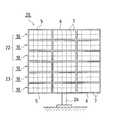
図6は、本発明の実施の形態1に係る集光型太陽光発電ユニットに搭載された太陽電池素子のレシーバでの配置状態を示す平面図である。  FIG. 6 is a plan view showing an arrangement state of the solar cell elements mounted on the concentrating solar power generation unit according toEmbodiment 1 of the present invention at the receiver.

本実施の形態では、太陽電池素子1は、GaAs系の化合物半導体を用いて公知の半導体製造プロセスによりPN接合、電極などを形成してウエファから受光領域7mm角のチップに加工されている。太陽電池素子1は、約60mm角の銅製のレシーバ2に裏面電極によって電気的、機械的に接続、接着(搭載)されている。レシーバ2の対角位置のコーナー部に基準穴2pが高精度に穿設され、この基準穴2pを基準に太陽電池素子1が位置決めされ接着される。  In the present embodiment, thesolar cell element 1 is processed from a wafer into a 7 mm square chip by forming a PN junction, an electrode, and the like by a known semiconductor manufacturing process using a GaAs compound semiconductor. Thesolar cell element 1 is electrically and mechanically connected and bonded (mounted) to acopper receiver 2 of about 60 mm square by a back electrode. Areference hole 2p is drilled with high accuracy in a corner portion of the diagonal position of thereceiver 2, and thesolar cell element 1 is positioned and bonded with reference to thereference hole 2p.

太陽電池素子1と並列にバイパスダイオードDiが接続してあり、太陽光Lsの遮断などにより太陽電池素子1が抵抗として動作する場合に隣接する太陽電池素子1への電流経路を構成して、特定の太陽電池素子1が発電機能を果たさない場合でも全体として発電機能を維持できる構成としてある。  When a bypass diode Di is connected in parallel with thesolar cell element 1 and thesolar cell element 1 operates as a resistance by blocking sunlight Ls or the like, a current path to the adjacentsolar cell element 1 is configured and specified. Even if thesolar cell element 1 does not perform the power generation function, the power generation function can be maintained as a whole.

レシーバ2の表面は、電気的接続が必要となる太陽電池素子1の基板電極、バイパスダイオードDiの基板電極が接続される領域、基板電極接続部2bの領域で露出してあり、他の表面領域は絶縁性レジスト2iで被覆してある。絶縁性レジスト2iの表面の一部に出力取り出しのための電極となる表面電極接続部2tが適宜の薄板状の導体で形成してある。  The surface of thereceiver 2 is exposed in the region of the substrate electrode of thesolar cell element 1 that requires electrical connection, the region to which the substrate electrode of the bypass diode Di is connected, and the region of the substrateelectrode connection portion 2b. Is covered with an insulating resist 2i. A surfaceelectrode connection portion 2t serving as an electrode for extracting output is formed on a part of the surface of the insulating resist 2i with an appropriate thin plate-like conductor.

太陽電池素子1の対向するチップ両端部に形成された表面電極1aは、ワイヤWsを介して表面電極接続部2tにワイヤボンディングしてあり、基板電極接続部2bとの間で出力を取り出すことができる。また、バイパスダイオードDiの表面電極は、ワイヤWdを介して表面電極接続部2tにワイヤボンディングしてあり、バイパス動作を行うことができる。  Thesurface electrodes 1a formed on the opposite ends of the chip of thesolar cell element 1 are wire-bonded to the surfaceelectrode connection portion 2t via the wire Ws, and the output can be taken out with the substrateelectrode connection portion 2b. it can. Further, the surface electrode of the bypass diode Di is wire-bonded to the surfaceelectrode connecting portion 2t via the wire Wd, and a bypass operation can be performed.

本実施の形態では太陽電池素子1のチップ表面に反射防止膜が形成されており、反射防止膜内の多重反射のため波長によって反射率は変化するが、入射角の増加に伴って反射率は高くなる傾向があるため、受光領域表面における反射損失を低減することができる。反射防止膜としてはTiO/Al22膜を採用してある。表面電極1aを部分的に露出させて電気的に接続する必要があるが、厚さ100nm程度の厚みであるため、ワイヤーヘッドを摩擦により溶解させて圧着接続させるウエッジボンディングを行う。つまり、表面電極1a上の反射防止膜を研磨し、表面電極1aを部分的に露出させてワイヤボンディングを行う。したがって、反射防止膜を取り除く工程なしに表面電極1aを表面電極接続部2tに電気的に接続することが可能である。In the present embodiment, an antireflection film is formed on the chip surface of thesolar cell element 1, and the reflectivity changes depending on the wavelength due to multiple reflection in the antireflection film, but the reflectivity increases with an increase in incident angle. Since it tends to increase, reflection loss on the surface of the light receiving region can be reduced. A TiO / Al2 O2 film is employed as the antireflection film. Thesurface electrode 1a needs to be partially exposed and electrically connected. However, since the thickness is about 100 nm, wedge bonding is performed in which the wire head is melted by friction to be crimped. That is, the antireflection film on thesurface electrode 1a is polished, and thesurface electrode 1a is partially exposed to perform wire bonding. Therefore, it is possible to electrically connect thesurface electrode 1a to the surfaceelectrode connecting portion 2t without removing the antireflection film.

ワイヤボンディングに際し、ワイヤーヘッドを摩擦する方向は、表面電極1aのパターン形状の長手方向として振幅させることにより、表面電極1aの短辺幅を短く設定することが可能となる。本実施の形態においては、ワイヤWsの直径の約2倍程度の摩擦幅があれば十分でありワイヤ径が250μm程度の場合、圧着部の幅は約750μm程度である。  When wire bonding is performed, the direction in which the wire head is rubbed is amplified as the longitudinal direction of the pattern shape of thesurface electrode 1a, whereby the short side width of thesurface electrode 1a can be set short. In the present embodiment, a friction width of about twice the diameter of the wire Ws is sufficient, and when the wire diameter is about 250 μm, the width of the crimping portion is about 750 μm.

また、各表面電極1aに対してワイヤWsを1本にする場合は、効率よく集電するためにワイヤWsの圧着位置は表面電極1aの中央付近とすることが好ましい。本実施の形態では各表面電極1aに対してワイヤWsを1本としてあるが、各表面電極1aに対して複数本接続しても良い。表面電極1aのパターン形状の長手方向にワイヤーヘッドを摩擦させれば、ワイヤWsの表面電極接続部2tへの張り出し方向はいずれでも構わないが、表面電極接続部2tへ最短距離の経路を辿るのが好ましい。  Further, when one wire Ws is used for eachsurface electrode 1a, the crimping position of the wire Ws is preferably near the center of thesurface electrode 1a in order to collect current efficiently. In the present embodiment, one wire Ws is provided for eachsurface electrode 1a, but a plurality of wires may be connected to eachsurface electrode 1a. If the wire head is rubbed in the longitudinal direction of the pattern shape of thesurface electrode 1a, the protruding direction of the wire Ws to the surfaceelectrode connecting portion 2t may be any, but the route of the shortest distance to the surfaceelectrode connecting portion 2t is followed. Is preferred.

表面電極接続部2tは太陽電池素子1とバイパスダイオードDiとの並列接続を容易にするために、各表面電極1aの長手方向に対して直交方向に配置されるのが好ましい。太陽電池素子1の対向するチップ両端部に形成された表面電極1aをワイヤボンディングにより表面電極接続部2tに電気的に接続することで、電極形状の短辺幅を短く設定でき、太陽電池素子1のチップあたりの発電面積比率を大きくすることができることから製造コストを削減することができる。  The surfaceelectrode connection part 2t is preferably arranged in a direction orthogonal to the longitudinal direction of eachsurface electrode 1a in order to facilitate parallel connection of thesolar cell element 1 and the bypass diode Di. By electrically connecting thesurface electrodes 1a formed at the opposite ends of the chip of thesolar cell element 1 to the surfaceelectrode connection part 2t by wire bonding, the short side width of the electrode shape can be set short, and thesolar cell element 1 Since the power generation area ratio per chip can be increased, the manufacturing cost can be reduced.

太陽電池素子1の表面に不透明で厚みを有する電極などが存在する場合は入射角の増大により電極の陰による入射光損失が大きくなるが、チップ両端部に表面電極1aを形成する本実施の形態によればそのような問題が抑制されることから発電効率が向上する。また、ワイヤWsを用いることにより太陽電池素子1の表面を被覆する電極の面積が小さくなり、発電効率が向上する。  In the case where an electrode having an opaque thickness is present on the surface of thesolar cell element 1, the incident light loss due to the shadow of the electrode increases due to the increase of the incident angle, but this embodiment forms thesurface electrode 1a at both ends of the chip. Therefore, since such a problem is suppressed, power generation efficiency is improved. Moreover, the area of the electrode which coat | covers the surface of thesolar cell element 1 becomes small by using the wire Ws, and electric power generation efficiency improves.

なお、太陽電池素子1、及びバイパスダイオードDiの接合はワイヤボンディングが好ましいが、半田接合や、溶接による接合でも良い。  Thesolar cell element 1 and the bypass diode Di are preferably joined by wire bonding, but may be joined by soldering or welding.

表面電極接続部2t、基板電極接続部2bに対して隣接する太陽電池素子1との接続を行うための導電リード2cがそれぞれ接続してあり、導電リード2cを直列あるいは並列に接続することにより大容量の発電が可能となる。  Conductive leads 2c for connecting to the adjacentsolar cell element 1 are connected to the surfaceelectrode connecting portion 2t and the substrateelectrode connecting portion 2b, respectively, and large by connecting the conductive leads 2c in series or in parallel. Capacity power generation is possible.

本実施の形態では太陽電池素子1としてGaAs系化合物半導体太陽電池を用いたが、これに限定されずSi太陽電池や、それら太陽電池を組み合わせたメカニカルスタック型太陽電池などを使用してもよい。  In the present embodiment, a GaAs-based compound semiconductor solar cell is used as thesolar cell element 1. However, the present invention is not limited to this, and a Si solar cell, a mechanical stack type solar cell combining these solar cells, or the like may be used.

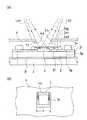
図7は、本発明の実施の形態1に係る集光型太陽光発電ユニットに搭載された太陽電池素子の実装状態および透過穴の配置状態を示す説明図であり、(A)は側面から見た状態を透視的に示す側面透視図であり、(B)は集光レンズの側から遮光板(透過穴)を見た平面図である。  FIG. 7 is an explanatory view showing the mounting state of the solar cell elements and the arrangement state of the transmission holes mounted on the concentrating solar power generation unit according toEmbodiment 1 of the present invention, and (A) is a side view. FIG. 6B is a side perspective view showing the state in a transparent manner, and FIG. 5B is a plan view of the light shielding plate (transmission hole) viewed from the condenser lens side.

レシーバ2の露出表面に半田接合された太陽電池素子1およびバイパスダイオードDiは、封止ダム2sdにより周囲(平面状周囲)を囲まれ、封止樹脂2srで樹脂封止される。封止樹脂の表面に封止ガラス2sgを配置することにより(遮光板4側の表面での)樹脂封止の耐湿性を向上することができる。なお、封止ガラスの上には、MgF2などの適当な反射防止膜が形成されていても良い。封止ダム2sdは例えば白色などのシリコーン樹脂、封止樹脂2srは例えば透光性の大きいシリコーン樹脂で形成する。樹脂封止の工程は、まず封止ダム4sdを形成する工程、次に封止ダム4sdの内側に封止樹脂2srを注入充填する工程、適宜の硬度とした封止樹脂2srの表面にガラスを載置する工程で構成される。Solar cell element 1 and bypass diode Di solder-bonded to the exposed surface ofreceiver 2 are surrounded by a sealing dam 2sd (planar periphery) and are resin-sealed with sealing resin 2sr. By disposing the sealing glass 2sg on the surface of the sealing resin, the moisture resistance of the resin sealing (on the surface on thelight shielding plate 4 side) can be improved. An appropriate antireflection film such as MgF2 may be formed on the sealing glass. The sealing dam 2sd is formed of, for example, a white silicone resin, and the sealing resin 2sr is formed of, for example, a highly transparent silicone resin. The resin sealing step includes a step of first forming the sealing dam 4sd, a step of injecting and filling the sealing resin 2sr inside the sealing dam 4sd, and a glass on the surface of the sealing resin 2sr having an appropriate hardness. It is comprised by the process to mount.

本実施の形態ではレシーバ2は銅製であり、集光された太陽光Lsが照射されることによって極めて高温になる太陽電池素子1に対して放熱手段としても機能する。太陽電池素子1を搭載したレシーバ2は、アルミニウム製の実装板3に絶縁熱伝導シート3iを介して接着され、絶縁状態を維持しながら太陽電池素子1の熱を実装板3から大気に放熱する。なお、絶縁熱伝導シート3iとしては、酸化アルミニウムなどの絶縁性金属を金属フィラとして含むシリコーン系ゴムを適用することができる。また、実装板3には適宜放熱フィン(不図示)を設けることが可能であり、特にレシーバ2に対応する位置に配置することにより大きな放熱効果を得ることができる。  In this embodiment, thereceiver 2 is made of copper, and also functions as a heat radiating unit for thesolar cell element 1 that becomes extremely high when irradiated with the concentrated sunlight Ls. Thereceiver 2 on which thesolar cell element 1 is mounted is bonded to analuminum mounting plate 3 via an insulating heat conductive sheet 3i, and dissipates heat of thesolar cell element 1 from the mountingplate 3 to the atmosphere while maintaining an insulating state. . As the insulating heat conductive sheet 3i, a silicone rubber containing an insulating metal such as aluminum oxide as a metal filler can be applied. Further, the mountingboard 3 can be appropriately provided with heat radiating fins (not shown), and in particular, by disposing it at a position corresponding to thereceiver 2, a large heat radiating effect can be obtained.

レシーバ2と実装板3の相互間の位置決め、固定は、レシーバ2に設けられた基準穴2pに対して、実装板3に正確に位置合わせした受穴3pを形成し、基準穴2pおよび受穴3pに絶縁被覆されたリベット2rを挿通して固定することにより精度良く行うことができる。  Positioning and fixing between thereceiver 2 and the mountingboard 3 are performed by forming a receivinghole 3p accurately aligned with the mountingboard 3 with respect to thereference hole 2p provided in thereceiver 2, and thereference hole 2p and the receiving hole. By inserting and fixing therivet 2r that is covered withinsulation 3p, it can be performed with high accuracy.

透過穴4aの形状およびサイズは、受光領域7mm角の太陽電池素子1、焦点距離(太陽電池素子1の受光領域に平面状に集光する距離:光学的距離)300mmの集光レンズ7に対して、長さb=13mm角の開口としてある。なお、遮光板4と実装板3との間隔を適宜調整しておくことは言うまでもない。  The shape and size of thetransmission hole 4a are as follows for thesolar cell element 1 having a light receiving area of 7 mm square and the condensinglens 7 having a focal length (distance condensing in a planar shape on the light receiving area of the solar cell element 1: optical distance). Thus, the opening has a length b = 13 mm square. Needless to say, the interval between thelight shielding plate 4 and the mountingplate 3 is appropriately adjusted.

また、透過穴4aの形状はb=13mm角のサイズに打ち抜きすることもできるが、透過穴4aの周囲を絞り加工して周辺に屈曲部4cを形成し、斜めから透過して太陽電池素子1以外の部分を照射する恐れのある太陽光Lsdを遮断する機能(角度)を持たせて形成することが好ましい。  Although the shape of thetransmission hole 4a can be punched to a size of b = 13 mm square, the periphery of thetransmission hole 4a is drawn to form a bent portion 4c around thetransmission hole 4a, and is transmitted obliquely to thesolar cell element 1. It is preferable to form it with the function (angle) which interrupts sunlight Lsd which may irradiate other parts.

つまり、遮光板4は、透過穴4aの周縁を実装板3の側に折り曲げた屈曲部4cを有する構成により、透過穴4aに対して斜めに照射する太陽光Lsが遮光板4の裏側(すなわち実装板3および太陽電池素子1側)へ透過することを防止できることから、太陽電池素子1の周辺部での太陽光Lsによる損傷を防止することが可能となる。  That is, thelight shielding plate 4 has a bent portion 4c in which the periphery of thetransmission hole 4a is bent to the mountingplate 3 side, so that the sunlight Ls irradiated obliquely to thetransmission hole 4a is behind the light shielding plate 4 (that is, Since it is possible to prevent transmission to the mountingplate 3 and thesolar cell element 1 side), damage due to sunlight Ls in the peripheral portion of thesolar cell element 1 can be prevented.

さらに、屈曲部4cの集光レンズ7側の表面(入射側表面)4sを鏡面加工することにより、屈曲部4cに照射された太陽光Lsを太陽電池素子1側に反射させて入射効率を高めることができる。  Further, the surface (incident side surface) 4s on thecondenser lens 7 side of the bent portion 4c is mirror-finished, so that the sunlight Ls irradiated to the bent portion 4c is reflected to thesolar cell element 1 side to increase the incident efficiency. be able to.

<実施の形態2>
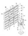
図8は、本発明の実施の形態2に係る集光型太陽光発電装置の受光面を垂直状態とした正面概要を示す正面図である。図9は、図8の集光型太陽光発電装置の背面概要を分解して示す分解斜視図である。
<Embodiment 2>
FIG. 8: is a front view which shows the front outline which made the light-receiving surface of the concentrating solar power generation device which concerns onEmbodiment 2 of this invention a vertical state. FIG. 9 is an exploded perspective view showing the rear outline of the concentrating solar power generation device of FIG. 8 in an exploded manner.

本実施の形態の集光型太陽光発電装置20は、実施の形態1に係る集光型太陽光発電ユニット10をフレーム5の長手方向と交差する短手方向で複数連結してある。この構成により、垂直方向と水平方向で重量バランスの取れた受光平面とすることができ、追尾駆動に適した平面形状とすることができる。  In the concentrating solarpower generation device 20 of the present embodiment, a plurality of concentrating solarpower generation units 10 according toEmbodiment 1 are connected in the short direction intersecting the longitudinal direction of theframe 5. With this configuration, it is possible to obtain a light receiving plane having a weight balance in the vertical direction and the horizontal direction, and to have a planar shape suitable for tracking drive.

つまり、嵌合溝5bを相互に嵌合して1群(例えば3個)のフレーム5を短手方向で連結し、また、分割して配置された実装板3相互間の短手方向にU字状の主桁部21を1群のフレーム5に対応配置して支持、連結することにより、垂直方向の上部側に発電モジュール22、下部側に発電モジュール23を構成してある。つまり、全体で集光型太陽光発電ユニット10の数は6個で良く、少ないユニット数で集光型太陽光発電装置20を構成することができることから機械的強度を確保し、生産性、量産性を向上することができる。  That is, thefitting grooves 5b are fitted to each other to connect a group (for example, three) of theframes 5 in the short direction, and the U in the short direction between the mountingboards 3 arranged separately. Apower generation module 22 is configured on the upper side in the vertical direction and apower generation module 23 is configured on the lower side by supporting and connecting the letter-shapedmain girder 21 corresponding to the group offrames 5. That is, the total number of concentrating solarpower generation units 10 may be six, and the concentrating solarpower generation device 20 can be configured with a small number of units, so that mechanical strength is ensured, and productivity and mass production are ensured. Can be improved.

フレーム5の長手方向を水平方向に配置することから、大面積で(フレーム5の全面を利用して)フレーム5を相互に押圧することができるのでフレーム5相互間の連結強度をより大きくでき、機械的強度が大きく安定した連結が可能となる。また、フレーム5相互を主桁部21で支持することから、機械的強度をさらに向上させることができる。  Since the longitudinal direction of theframes 5 is arranged in the horizontal direction, theframes 5 can be pressed against each other with a large area (using the entire surface of the frame 5), so that the connection strength between theframes 5 can be further increased. High mechanical strength and stable connection are possible. Further, since theframes 5 are supported by themain beam portion 21, the mechanical strength can be further improved.

また、実装板3は主桁部21に重ならないように配置されていることにより、太陽光発電装置20を現地に設置した後でもフレーム5を固定したままで実装板3を遮光板4から取り外すことが可能となり、保守点検、補修の作業性が向上する。  Further, since the mountingboard 3 is arranged so as not to overlap themain beam portion 21, the mountingboard 3 is removed from thelight shielding plate 4 while theframe 5 is fixed even after the photovoltaicpower generation device 20 is installed on site. This improves the workability of maintenance inspection and repair.

つまり、集光型太陽光発電装置20は、実施の形態1に係る集光型太陽光発電ユニット10を複数連結してあり、集光型太陽光発電ユニット10は、フレーム5の長手方向と交差する短手方向に連結する構成とした場合、構造的に安定したモジュールを構成することから、機械的強度が大きく自動追尾に適した平面形状とすることができ、大きな発電容量を生産性、作業性、信頼性良く、確実に実現することが可能となる。  That is, the concentrating solarpower generation device 20 is formed by connecting a plurality of concentrating solarpower generation units 10 according to the first embodiment, and the concentrating solarpower generation unit 10 intersects the longitudinal direction of theframe 5. When configured to be connected in the short direction, a module that is structurally stable can be configured, so that it can have a planar shape with high mechanical strength and suitable for automatic tracking. It is possible to realize with high reliability and reliability.

また、集光型太陽光発電装置20では、フレーム5の長手方向を水平方向に配置する構成とした場合、フレーム5相互間の連結をより強固にできることから機械的強度が大きく安定した連結が可能となる。  Further, in the concentrating solarpower generation device 20, when the longitudinal direction of theframes 5 is arranged in the horizontal direction, the connection between theframes 5 can be further strengthened, so that the mechanical strength is large and stable connection is possible. It becomes.

また、集光型太陽光発電装置20では、フレーム5の長手方向と交差する短手方向で、フレーム5を連結する主桁部21を備える構成とした場合、連結したフレーム5を確実に支持、連結することができることから、機械的強度のより大きい集光型太陽光発電装置を構成することができる。  Further, in the concentrating solarpower generation device 20, when themain girder portion 21 that connects theframes 5 is provided in a short direction that intersects the longitudinal direction of theframes 5, theconnected frames 5 are reliably supported. Since it can connect, the concentrating solar power generation device with larger mechanical strength can be comprised.

また、集光型太陽電池装置20では、現地に設置した後でもフレーム5を固定したままで実装板3および透光性保護板6をフレーム5、遮光板4から容易に取り外せることにより、現地での保守点検、補修を容易に行うことが可能となる。  In the concentratingsolar cell device 20, the mountingplate 3 and the translucentprotective plate 6 can be easily detached from theframe 5 and thelight shielding plate 4 while theframe 5 is fixed even after being installed on site. Maintenance inspection and repair can be easily performed.

集光型太陽光発電装置20の設置に際しては、発電モジュール22、23間をさらに、主桁結合部24によって機械的に強固に固定する。主桁結合部24は、追尾駆動部25を介して支柱26により適宜保持される。追尾駆動部25は、太陽光Lsを自動追尾するように水平方向の回動機能を有する旋回駆動部、垂直方向の回動機能を有する傾倒駆動部で構成される。傾倒駆動部が備える制御棒27の先端は発電モジュール22の背面に設けた固定金具27aに連結され制御性、安定性を向上してある。  When installing the concentrating solarpower generation apparatus 20, thepower generation modules 22 and 23 are further mechanically and firmly fixed by the mainbeam coupling portion 24. The maingirder coupling unit 24 is appropriately held by thesupport column 26 via thetracking drive unit 25. The trackingdrive unit 25 includes a turning drive unit having a horizontal rotation function and a tilting drive unit having a vertical rotation function so as to automatically track sunlight Ls. The tip of thecontrol rod 27 provided in the tilting drive unit is connected to afixture 27a provided on the back surface of thepower generation module 22 to improve controllability and stability.

フレーム5の長手方向の端面に対応する端面側壁28は、連結された複数のフレーム5を一体的に覆う板材により構成してあり、発電モジュール22、23それぞれに形成してある。もちろん、端面側壁28は、集光型太陽光発電ユニット10のそれぞれに対応して分割して形成されてもよい。  The endsurface side wall 28 corresponding to the end surface in the longitudinal direction of theframe 5 is formed of a plate material that integrally covers the plurality ofconnected frames 5, and is formed in each of thepower generation modules 22 and 23. Of course, the endsurface side wall 28 may be divided and formed corresponding to each of the concentrating solarpower generation units 10.

また、端面側壁28は、フレーム5内の温度上昇を防止するために通気可能な状態とされることが望ましい。即ち、塵芥などの進入を防ぎながら通気を確保できる通気孔あるいは網材を板材の一部に形成して構成されることが望ましい。  Further, it is desirable that the endface side wall 28 be in a state in which ventilation is possible in order to prevent a temperature rise in theframe 5. In other words, it is desirable to form a ventilation hole or netting material that can ensure ventilation while preventing entry of dust and the like in a part of the plate material.

なお、集光型太陽光発電ユニット10のみで追尾駆動される集光型太陽光発電装置とすることが可能であることは言うまでもない。  Needless to say, it is possible to provide a concentrating solar power generation device that is driven by the concentrating solarpower generation unit 10 alone.

本発明の実施の形態1に係る集光型太陽光発電ユニットの要部の配置関係を部分的に示す分解斜視図である。It is a disassembled perspective view which shows partially the arrangement | positioning relationship of the principal part of the concentrating solar power generation unit which concerns onEmbodiment 1 of this invention.図1の集光型太陽光発電ユニットの実装板とフレーム底部との位置決め・固定の状態を説明する説明図であり、(A)は実装板の斜視図、(B)は位置決め固定状態を示す断面図、(C)は緩い固定状態を示す断面図である。It is explanatory drawing explaining the state of positioning and fixing with the mounting board and frame bottom part of the concentrating photovoltaic power generation unit of FIG. 1, (A) is a perspective view of a mounting board, (B) shows a positioning fixed state. Sectional drawing, (C) is a sectional view showing a loosely fixed state.図1の集光型太陽光発電ユニットの透光性保護板とフレーム上端との位置決め・固定の状態を説明する説明図であり、(A)は透光性保護板などの斜視図、(B)は位置決め固定状態を示す断面図、(C)は固定状態を示す断面図である。It is explanatory drawing explaining the state of positioning and fixing with the translucent protection board and frame upper end of the concentrating photovoltaic power generation unit of FIG. 1, (A) is a perspective view, such as a translucent protection board, (B) ) Is a sectional view showing a positioning and fixing state, and (C) is a sectional view showing a fixing state.本発明の実施の形態1に係る集光型太陽光発電ユニットの長手方向での側面から見た要部の配置関係を透視的に示す概略側面図である。It is a schematic side view which shows perspectively the arrangement | positioning relationship of the principal part seen from the side surface in the longitudinal direction of the concentrating photovoltaic power generation unit which concerns onEmbodiment 1 of this invention.図4の矢符A−Aでの断面概要を示す拡大断面図である。It is an expanded sectional view which shows the cross-sectional outline | summary in the arrow AA of FIG.本発明の実施の形態1に係る集光型太陽光発電ユニットに搭載された太陽電池素子のレシーバでの配置状態を示す平面図である。It is a top view which shows the arrangement state in the receiver of the solar cell element mounted in the concentrating photovoltaic power generation unit which concerns onEmbodiment 1 of this invention.本発明の実施の形態1に係る集光型太陽光発電ユニットに搭載された太陽電池素子の実装状態および透過穴の配置状態を示す説明図であり、(A)は側面から見た状態を透視的に示す側面透視図であり、(B)は集光レンズの側から遮光板(透過穴)を見た平面図である。It is explanatory drawing which shows the mounting state of the solar cell element mounted in the concentrating photovoltaic power generation unit which concerns onEmbodiment 1 of this invention, and the arrangement | positioning state of a permeation | transmission hole, (A) sees through the state seen from the side surface FIG. 2B is a side perspective view schematically showing the light shielding plate (transmission hole) from the condenser lens side.本発明の実施の形態2に係る集光型太陽光発電装置の正面概要を示す正面図である。It is a front view which shows the front outline | summary of the concentrating solar power generation device which concerns onEmbodiment 2 of this invention.図8の集光型太陽光発電装置の背面概要を分解して示す分解斜視図である。It is a disassembled perspective view which decomposes | disassembles and shows the back surface outline | summary of the concentrating solar power generation device of FIG.

符号の説明Explanation of symbols

1 太陽電池素子
2 レシーバ
3 実装板
3a 鍔
3b 実装板位置合わせ部
4 遮光板
4b フレーム底部
4a 透過穴
4c 屈曲部
4d 実装板用突起部
4s 表面(入射側表面)
5 フレーム
5a 鍔
5b 嵌合溝
6 透光性保護板
6a 枠部
6b 保護板枠位置合わせ部
7 集光レンズ
10 集光型太陽光発電ユニット
11 構造体
20 集光型太陽光発電装置
21 主桁部
22 発電モジュール
23 発電モジュール
24 主桁結合部
26 支柱
Ls 太陽光
DESCRIPTION OFSYMBOLS 1Solar cell element 2Receiver 3Mounting board 3a 3 3b Mountingboard alignment part 4Shading board 4b Framebottom part 4a Transmission hole4c Bending part 4d Mounting board projection part 4s Surface (incident side surface)
5Frame 5a5b Fitting groove 6 Translucentprotective plate6a Frame portion 6b Protection plateframe alignment portion 7Condensing lens 10 Concentrating solarpower generation unit 11Structure 20 Concentrating solarpower generation device 21Main girder Section 22Power generation module 23Power generation module 24 Maingirder coupling section 26 Post Ls Sunlight

Claims (7)

Translated fromJapanese
集光レンズで集光した太陽光を太陽電池素子に照射して発電する集光型太陽光発電ユニットにおいて、
前記太陽電池素子を実装してある実装板と、
前記太陽電池素子の受光領域に太陽光を照射させる透過穴を有し前記実装板を覆う遮光板と、
該遮光板に対向して配置され前記受光領域に太陽光を集光する集光レンズと、
前記太陽電池素子と前記集光レンズとの位置を合わせて保持するフレームとを備え、
前記遮光板と前記フレームとは一体の金属板で形成された構造体とされ、前記遮光板は前記構造体の底部を構成し、前記フレームは前記構造体の側壁を構成し
前記実装板は、前記遮光板に装着されて長手方向の端辺の略中央が前記遮光板に固定されていること
を特徴とする集光型太陽光発電ユニット。
In a concentrating solar power generation unit that generates power by irradiating solar cell elements with sunlight condensed by a condensing lens,
A mounting plate on which the solar cell element is mounted;
A light shielding plate having a transmission hole for irradiating sunlight to the light receiving region of the solar cell element and covering the mounting board;
A condensing lens that is disposed to face the light shielding plate and collects sunlight in the light receiving region;
A frame that holds the solar cell element and the condensing lens in alignment with each other;
The light shielding plate and the frame are a structure formed of an integral metal plate, the light shielding plate constitutes the bottom of the structure, the frame constitutes a side wall of the structure,
The concentrating solar power generation unit, wherein the mounting plate is attached to the light shielding plate, and a substantially center of an end in a longitudinal direction is fixed to the light shielding plate .
前記遮光板は、前記透過穴の周縁を前記実装板側に折り曲げた屈曲部を有することを特徴とする請求項1に記載の集光型太陽光発電ユニット。2. The concentrating solar power generation unit according toclaim 1, wherein the light shielding plate has a bent portion obtained by bending the periphery of the transmission hole toward the mounting plate. 前記実装板は、前記太陽電池素子を複数配置してあることを特徴とする請求項1または請求項2に記載の集光型太陽光発電ユニット。The concentrating solar power generation unit according toclaim 1 , wherein the mounting plate includes a plurality of the solar cell elements. 前記集光レンズは、前記複数の太陽電池素子それぞれに対応して透光性保護板に配置され保持されていることを特徴とする請求項3に記載の集光型太陽光発電ユニット。4. The concentrating solar power generation unit according toclaim 3 , wherein the condensing lens is disposed and held on a translucent protective plate corresponding to each of the plurality of solar cell elements. 前記透光性保護板は長手方向の端辺の略中央を前記フレームの上端に固定してあることを特徴とする請求項4に記載の集光型太陽光発電ユニット。5. The concentrating solar power generation unit according toclaim 4 , wherein the translucent protective plate has a substantially center of an end in a longitudinal direction fixed to an upper end of the frame. 前記実装板および前記透光性保護板は、前記フレームの長手方向で複数に分割してあることを特徴とする請求項4または請求項5に記載の集光型太陽光発電ユニット。The concentrating solar power generation unit according toclaim 4 or 5 , wherein the mounting plate and the translucent protective plate are divided into a plurality in the longitudinal direction of the frame. 集光型太陽光発電ユニットを備える集光型太陽光発電装置において、
前記集光型太陽光発電ユニットは、請求項1ないし請求項6のいずれか一つに記載の集光型太陽光発電ユニットであり、追尾駆動される構成としてあることを特徴とする集光型太陽光発電装置。
In the concentrating solar power generation apparatus including the concentrating solar power generation unit,
The concentrating solar power generation unit is the concentrating solar power generation unit according to any one ofclaims 1 to 6 , and is configured to be driven for tracking. Solar power generator.
JP2005167526A2005-06-072005-06-07 Concentrating solar power generation unit and concentrating solar power generation deviceExpired - Fee RelatedJP4732015B2 (en)

Priority Applications (5)

Application NumberPriority DateFiling DateTitle
JP2005167526AJP4732015B2 (en)2005-06-072005-06-07 Concentrating solar power generation unit and concentrating solar power generation device
EP06757110AEP1895597A1 (en)2005-06-072006-06-07Condensing photovoltaic power generation unit and condensing photovoltaic power generation system, and condensing lens, condensing lens structure, and production method of condensing lens structure
PCT/JP2006/311403WO2006132265A1 (en)2005-06-072006-06-07Condensing photovoltaic power generation unit and condensing photovoltaic power generation system, and condensing lens, condensing lens structure, and production method of condensing lens structure
US11/921,465US8237044B2 (en)2005-06-072006-06-07Concentrating solar power generation unit, concentrating solar power generation apparatus, concetrating lens, concentrating lens structure, and method of manufacturing concentrating lens structure
AU2006256136AAU2006256136B8 (en)2005-06-072006-06-07Concentrating solar power generation unit, concentrating solar power generation apparatus, concentrating lens, concentrating lens structure, and method for manufacturing concentrating lens structure

Applications Claiming Priority (1)

Application NumberPriority DateFiling DateTitle
JP2005167526AJP4732015B2 (en)2005-06-072005-06-07 Concentrating solar power generation unit and concentrating solar power generation device

Publications (2)

Publication NumberPublication Date
JP2006344698A JP2006344698A (en)2006-12-21
JP4732015B2true JP4732015B2 (en)2011-07-27

Family

ID=37641452

Family Applications (1)

Application NumberTitlePriority DateFiling Date
JP2005167526AExpired - Fee RelatedJP4732015B2 (en)2005-06-072005-06-07 Concentrating solar power generation unit and concentrating solar power generation device

Country Status (1)

CountryLink
JP (1)JP4732015B2 (en)

Families Citing this family (19)

* Cited by examiner, † Cited by third party
Publication numberPriority datePublication dateAssigneeTitle
JP4571175B2 (en)*2007-09-282010-10-27行政院原子能委員会核能研究所 Concentrating solar power module alignment method
US8093492B2 (en)*2008-02-112012-01-10Emcore Solar Power, Inc.Solar cell receiver for concentrated photovoltaic system for III-V semiconductor solar cell
US8759138B2 (en)2008-02-112014-06-24Suncore Photovoltaics, Inc.Concentrated photovoltaic system modules using III-V semiconductor solar cells
US9331228B2 (en)2008-02-112016-05-03Suncore Photovoltaics, Inc.Concentrated photovoltaic system modules using III-V semiconductor solar cells
JP5153447B2 (en)*2008-05-092013-02-27シャープ株式会社 Concentrating solar power generation unit and concentrating solar power generation device
JP2010034134A (en)*2008-07-252010-02-12Sharp CorpConcentrating solar power generation apparatus, and method and device for manufacturing the same
JP5089564B2 (en)*2008-12-052012-12-05シャープ株式会社 Concentrating solar power generator
US9806215B2 (en)2009-09-032017-10-31Suncore Photovoltaics, Inc.Encapsulated concentrated photovoltaic system subassembly for III-V semiconductor solar cells
US9012771B1 (en)2009-09-032015-04-21Suncore Photovoltaics, Inc.Solar cell receiver subassembly with a heat shield for use in a concentrating solar system
CN103430325A (en)*2011-01-262013-12-04弗兰霍菲尔运输应用研究公司Photovoltaic concentrator receiver and use thereof
KR101203988B1 (en)2011-02-252012-11-22주식회사 상보High efficiency sollar cell grafted assistant condenser
DE202011108836U1 (en)*2011-12-082011-12-29Grenzebach Maschinenbau Gmbh Apparatus for the industrial production of photovoltaic concentrator modules
WO2013132919A1 (en)*2012-03-092013-09-12シャープ株式会社Assembled structure and light collecting type photovoltaic power generating unit
CN102646738B (en)*2012-05-022015-07-01天津蓝天太阳科技有限公司Internal wiring shading structure of spotlight photovoltaic assembly
EP2725628B1 (en)*2012-10-232020-04-08LG Electronics, Inc.Solar cell module
JP6354843B2 (en)*2014-06-272018-07-11住友電気工業株式会社 Solar power generation module and solar power generation panel
US11894804B2 (en)2014-06-272024-02-06Sumitomo Electric Industries, Ltd.Photovoltaic module, photovoltaic panel, and production method for photovoltaic module
JP6631436B2 (en)*2016-08-032020-01-15住友電気工業株式会社 Concentrating solar power module, concentrating solar power panel, and concentrating solar power generation device
US20220029580A1 (en)*2018-10-152022-01-27Sumitomo Electric Industries, Ltd.Shield plate for concentrator photovoltaic power generation module, concentrator photovoltaic power generation module, and method of manufacturing concentrator photovoltaic power generation module

Family Cites Families (6)

* Cited by examiner, † Cited by third party
Publication numberPriority datePublication dateAssigneeTitle
JPS572582A (en)*1980-06-071982-01-07Toyohashi Gijutsu Kagaku DaigakuSolar battery type generator
JP2000268749A (en)*1999-03-152000-09-29Matsushita Electronics Industry CorpFlat-panel display device
JP3580240B2 (en)*2000-10-202004-10-20松下電器産業株式会社 Semiconductor device and method of manufacturing semiconductor device
JP2003174183A (en)*2001-12-072003-06-20Daido Steel Co Ltd Concentrating solar power generator
JP3836401B2 (en)*2002-05-302006-10-25アンリツ株式会社 Optical device
JP4306265B2 (en)*2003-02-042009-07-29株式会社ニコン Solid-state imaging device

Also Published As

Publication numberPublication date
JP2006344698A (en)2006-12-21

Similar Documents

PublicationPublication DateTitle
JP4732015B2 (en) Concentrating solar power generation unit and concentrating solar power generation device
WO2006132265A1 (en)Condensing photovoltaic power generation unit and condensing photovoltaic power generation system, and condensing lens, condensing lens structure, and production method of condensing lens structure
AU2007303511B2 (en)Solar cell, concentrating solar power generation module, concentrating solar power generation unit, method of manufacturing solar cell, and solar cell manufacturing apparatus
AU2009263554B2 (en)Solar cell, concentrating solar power generation module and solar cell manufacturing method
JP4953745B2 (en) Concentrating solar power generation unit and concentrating solar power generation device
US9464783B2 (en)Concentrated photovoltaic panel
US20100236601A1 (en)Solar cell, concentrating photovoltaic power generation module, concentrating photovoltaic power generation unit and solar cell manufacturing method
JP2011138970A (en)Concentrating solar battery, concentrating solar battery module, and method of manufacturing the same
JP4986875B2 (en) Solar cell and concentrating solar power generation module
CN106208949B (en)Light concentrating photovoltaic module, condensation photovoltaic panel and condensation photovoltaic equipment
JP4794402B2 (en) Solar cell and concentrating solar power generation unit
JP2013012605A (en)Light collection type solar light power generation apparatus and manufacturing method of the same
JP2000091612A (en) Concentrating tracking power generator
JP5013684B2 (en) Condensing lens, condensing lens structure, concentrating solar power generation device, and manufacturing method of condensing lens structure
US7868244B2 (en)Solar CPV cell module and method of safely assembling, installing, and/or maintaining the same
JPWO2012160994A1 (en) Concentrating solar cell and manufacturing method thereof
WO2010027083A1 (en)Solar cells, concentrating solar generator modules, and solar cell manufacturing method
JP2001036120A (en) Solar cell assembly and method of manufacturing the same
JP4454666B2 (en) Solar cell, concentrating solar power generation module, concentrating solar power generation unit, and solar cell manufacturing method
JP4693793B2 (en) Solar cell, concentrating solar power generation module, concentrating solar power generation unit, and solar cell manufacturing method
JP2012015406A (en)Concentrating photovoltaic generation module
KR101357200B1 (en)Thin concentrator photovoltaic module
KR20150049336A (en)High concentrating photovoltaic module
KR101437909B1 (en)Secondary optical element having facility protecting carrier and concentrating photovoltaic module including the same
KR20150049757A (en)High concentrating photovoltaic module for easily arraying lens plate

Legal Events

DateCodeTitleDescription
A621Written request for application examination

Free format text:JAPANESE INTERMEDIATE CODE: A621

Effective date:20070822

A131Notification of reasons for refusal

Free format text:JAPANESE INTERMEDIATE CODE: A131

Effective date:20090317

A521Request for written amendment filed

Free format text:JAPANESE INTERMEDIATE CODE: A523

Effective date:20090518

RD02Notification of acceptance of power of attorney

Free format text:JAPANESE INTERMEDIATE CODE: A7422

Effective date:20090518

A131Notification of reasons for refusal

Free format text:JAPANESE INTERMEDIATE CODE: A131

Effective date:20100105

A521Request for written amendment filed

Free format text:JAPANESE INTERMEDIATE CODE: A523

Effective date:20100223

A02Decision of refusal

Free format text:JAPANESE INTERMEDIATE CODE: A02

Effective date:20101221

A521Request for written amendment filed

Free format text:JAPANESE INTERMEDIATE CODE: A523

Effective date:20110314

A911Transfer to examiner for re-examination before appeal (zenchi)

Free format text:JAPANESE INTERMEDIATE CODE: A911

Effective date:20110323

TRDDDecision of grant or rejection written
A01Written decision to grant a patent or to grant a registration (utility model)

Free format text:JAPANESE INTERMEDIATE CODE: A01

Effective date:20110419

A01Written decision to grant a patent or to grant a registration (utility model)

Free format text:JAPANESE INTERMEDIATE CODE: A01

A61First payment of annual fees (during grant procedure)

Free format text:JAPANESE INTERMEDIATE CODE: A61

Effective date:20110420

FPAYRenewal fee payment (event date is renewal date of database)

Free format text:PAYMENT UNTIL: 20140428

Year of fee payment:3

R150Certificate of patent or registration of utility model

Free format text:JAPANESE INTERMEDIATE CODE: R150

LAPSCancellation because of no payment of annual fees

[8]ページ先頭

©2009-2025 Movatter.jp