JP4728067B2 - Seat switch module - Google Patents
Seat switch moduleDownload PDFInfo
- Publication number
- JP4728067B2 JP4728067B2JP2005239129AJP2005239129AJP4728067B2JP 4728067 B2JP4728067 B2JP 4728067B2JP 2005239129 AJP2005239129 AJP 2005239129AJP 2005239129 AJP2005239129 AJP 2005239129AJP 4728067 B2JP4728067 B2JP 4728067B2
- Authority
- JP
- Japan
- Prior art keywords
- sheet
- light
- switch module
- light guide
- light emitting
- Prior art date
- Legal status (The legal status is an assumption and is not a legal conclusion. Google has not performed a legal analysis and makes no representation as to the accuracy of the status listed.)
- Expired - Lifetime
Links
Images


Landscapes
- Push-Button Switches (AREA)
Description
Translated fromJapanese本発明は、各種電子機器の操作パネルに搭載される照明機能を有したシートスイッチモジュールに関するものである。 The present invention relates to a sheet switch module having an illumination function mounted on an operation panel of various electronic devices.
従来、携帯電話機や携帯情報端末機等の各種電子機器に搭載されている操作パネルには、照明機能を組み込んだキースイッチを用いて構成されているものが多い。このような照明機能としては、前記キースイッチを構成する個々の押圧部(キートップ)に光源(発光素子)を個別に対応して配置させたり、導光板を使用することで、最小限の発光素子で効率よく各キートップを照明させたりするといった構成がとられている(特許文献1)。図8は、導光板を使用したキースイッチ1の構成例を示したものである。このキースイッチ1は、固定接点3や配線パターンが形成された回路基板2と、前記固定接点3上に配設されるタクトバネからなる可動接点4と、回路基板2上に配置される導光板5と、この導光板5の側面を照射する発光素子6と、前記導光板5を貫通して可動接点4を押圧するキートップ7とで構成されている。このキースイッチ1では、前記導光板5を貫通するキートップ7の下端部に前記発光素子6から導光された光を照射することでキートップ7全体を照明するようになっている。 2. Description of the Related Art Conventionally, many operation panels mounted on various electronic devices such as a mobile phone and a portable information terminal are configured using a key switch incorporating a lighting function. As such an illumination function, light emission (minimum light emission) can be minimized by individually arranging light sources (light emitting elements) corresponding to the individual pressing portions (key tops) constituting the key switch or using a light guide plate. A configuration is adopted in which each key top is efficiently illuminated with an element (Patent Document 1). FIG. 8 shows a configuration example of the
また、近年の電子機器の薄型化に対応させるため、照明機能を有しながら、さらに薄型化したキースイッチ(特許文献2)も知られている。図9は、特許文献2に記載されているキースイッチ11の断面構造を示したものである。このキースイッチ11は、固定接点13が形成された回路基板12、前記固定接点13上に配置される可動接点14からなるシートスイッチ部18と、このシートスイッチ部18の上方を覆う導光板15と、この導光板15の前記可動接点14が形成されている上部に位置するキートップ17とを有して形成されている。このキースイッチ11にあっては、前記回路基板12の一端に配設された発光素子16から発せられる光を導光板15の側面に照射することで、導光板15全体を発光させ、前記キートップ17を下面側から照明する構造となっている。
上述したような、個々のキートップの近傍に発光素子を個別に配設したような構造のキースイッチにあっては、キートップの数が増えるにしたがって発光素子を増設しなければならないため、消費電力の増加と共に、キースイッチ自体が大型化してしまうといった問題がある。また、図8に示したキースイッチ1にあっては、導光板5によって光をキートップに向けて導光させるため、発光素子6の個数は少なくて済むが、この発光素子6から発せられる光を漏れなく効率よく側面側から導くために、導光板5の厚みを一定以上厚くして形成しなければならない。しかしながら、前記導光板5を厚くすると、これに伴ってキースイッチ1全体の厚みも増すため、薄型化が図られないという問題がある。 In a key switch having a structure in which light emitting elements are individually arranged in the vicinity of individual key tops as described above, the number of light emitting elements must be increased as the number of key tops increases. There is a problem that the key switch itself increases in size as the power increases. Further, in the
一方、上記図9に示したキースイッチ11にあっては、発光素子16から出射される光を導光板15の一端に入射させて全体に導光する構造であるため、発光素子16から離れた箇所のキートップ17の輝度が低くなり、輝度のバラツキが目立つといった問題があった。また、前記導光板15は、シートスイッチ部18の上に載置しただけの構成になっているので、導光板15とシートスイッチ部18との間に隙間が生じやすく、さらに、前記導光板15の端部に配置される発光素子16との間にも隙間が生じやすい構造となっている。このような隙間が前記導光板15の周辺に存在すると、この隙間から発光漏れが生じてしまい、キートップ17に透過する光量の不足や輝度バラツキが発生するといった問題があった。このため、キートップ17のみを集中的に発光させるといったような照明効果が得られなかった。 On the other hand, since the
そこで、本発明の目的は、発光素子から発せられる光を漏れなく且つ効率よく押圧部に向けて導光させると共に、前記押圧部をバラツキなく高輝度で発光表示させることのできるキースイッチと照明機能とが一体となったシートスイッチモジュールを提供することである。 SUMMARY OF THE INVENTION Accordingly, an object of the present invention is to provide a key switch and an illumination function capable of guiding light emitted from a light emitting element toward a pressing portion efficiently without leaking and displaying the pressing portion with high brightness without variation. Is to provide a sheet switch module integrated with the above.
上記課題を解決するために、本発明のシートスイッチモジュールは、固定接点が複数配置された回路基板と、この回路基板上に配置される側面発光型の発光ダイオードと、前記各固定接点の上方に被さるように配置されるドーム型の金属材で形成されたタクトバネと、このタクトバネを前記回路基板上に被覆保持するシート材とを備え、このシート材の上から前記タクトバネの上面を押圧することによって前記固定接点に導通してスイッチング回路を形成するシートスイッチモジュールであって、前記シート材には、前記タクトバネを被覆保持する箇所に対応し且つ各タクトバネの形状に対応する形状からなるエンボス部が設けられると共に、該エンボス部の外周部にはタクトバネの外形形状に沿うような立ち上がり部が形成され、この立ち上がり部からタクトバネの上面に沿って前記発光ダイオードから出射される光を導光する導光性シートで構成されていることを特徴とする。In order to solve the above problems, a seat switch module according to the present invention includes a circuit board on which aplurality of fixed contacts are arranged, aside-emitting light emitting diode arranged on the circuit board, and aboveeach of the fixed contacts.A tact spring formed of adome-shaped metal material disposed so as to be covered; and a sheet materialthat covers and holds thetact spring on the circuit board; and by pressingthe upper surface of thetact spring from above the sheet material a seat switch modules forming a switching circuit electrically connected to the fixed contact,the sheet material isembossed portion is provided comprising a shape corresponding to the shape of the corresponding and respective Takutobane in place covering holds the Takutobane In addition, a rising portion is formed on the outer peripheral portion of the embossed portion so as to follow the outer shape of the tact spring. It characterized in that it consists of a light guiding sheet for guiding light emitted from thelight emitting diode alongthe rising portion on the upper surface of theTakutobane.
本発明のシートスイッチモジュールは、導光性シートがスイッチ操作の押圧部であるドーム型の金属材で形成されたタクトバネの上面に沿って被覆されているため、側面発光型の発光ダイオードから出射された光をタクトバネの上面に沿って導光させながら上方に向けて高輝度で発光表示させることができる。これによって、暗所でのキー入力操作が容易になると共に、キートップを配置した際にもその表面に印刷等で形成されている文字や記号等を視認性よく表示させることができる。
In the sheet switch module of the present invention, since the light guide sheet is covered along the upper surface ofa tact spring formed of adome-shaped metal material that is a pressing portion for switch operation,the light is emitted from aside-emitting light emitting diode. The light can be emitted and displayed with high brightness upward while being guided alongthe upper surface of thetact spring . This facilitates key input operation in a dark place, and even when the key top is arranged, characters, symbols, etc. formed on the surface by printing or the like can be displayed with high visibility.
以下、添付図面に基づいて本発明に係るシートスイッチモジュールの実施形態を詳細に説明する。 Hereinafter, embodiments of a seat switch module according to the present invention will be described in detail with reference to the accompanying drawings.
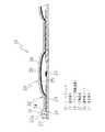
図1及び図2に示すように、本発明のシートスイッチモジュール(以下、単にシートスイッチという)21は、固定接点22及び電極パターン23、その他図示しないコネクタ等が形成されたフレキシブル回路基板(FPC)24と、前記固定接点22上に配置される可動接点25と、この可動接点25の上面に密着してFPC24全体を被覆する導光性シート26と、この導光性シート26の一端に配置される発光素子27とで構成されている。 As shown in FIGS. 1 and 2, a sheet switch module (hereinafter simply referred to as a sheet switch) 21 according to the present invention includes a flexible circuit board (FPC) on which
FPC24は、例えば、携帯電話機の操作パネルのシートスイッチとして形成される場合は、その操作パネルと略同様な形状及び大きさに形成され、数字キーやアルファベットキー、その他のファンクションキー等が配置される箇所に合わせて前記固定接点22が複数設けられる。前記可動接点25は、適度なクリック感を得るために薄い金属材によるドーム型のタクトバネで形成され、前記各固定接点22に対応してその上方に被さるように配置されている。また、可動接点25の上面は、一例では反射率を高めるために鏡面加工が施されており、前記FPC24上に実装されている発光素子27から導光性シート26によって導かれる光を効率よく反射する。 For example, when the FPC 24 is formed as a seat switch of an operation panel of a cellular phone, the FPC 24 is formed to have substantially the same shape and size as the operation panel, and numeric keys, alphabet keys, other function keys, and the like are arranged. A plurality of the
導光性シート26は、前記FPC24と略同じ形状及び大きさに形成された透明若しくは半透明の薄いシート材からなり、例えば、アクリル樹脂、シリコン樹脂、ポリカーボネート樹脂又はポリエチレンテレフタレート樹脂など導光性の高い材料によって形成するのが好ましい。また、導光性シート26の厚みは特に限定されるものではないが、導光効率及び前記可動接点25への密着性を考慮して0.05mm〜0.3mmの範囲、特に0.1mm前後で形成されるのが好ましい。この導光性シート26には、図1乃至図3に示すように、前記可動接点25を被覆保持する箇所にエンボス部29を予め形成しておくのが望ましい。このエンボス部29は、前記可動接点25の外形形状に対応して形成されるもので、その周囲全体に立ち上がり部32が形成されている。この立ち上がり部32は、後述するように、導光性シート26の内部に導かれた光が可動接点25の周囲近傍で光の進路を変更させ易くするためのもので、それによって可動接点25の上面で光を散乱し易くしている。シートスイッチ21を実際に組み立てる際には、エンボス部29を含む導光性シート26の裏面全体に透明な粘着剤28を一様に塗布し、エンボス部29の粘着面に可動接点25を接着保持させ、これを前記固定接点22が形成されているFPC24の上面に位置合わせした後、密着させてFPC24の上面を被覆する。なお、前記導光性シート26に上述したようなエンボス部29を予め設けずに、平面状シートのまま直接前記可動接点25を粘着させ、これを加熱及び加圧等の手段によって、可動接点25の外形形状に沿って密着成形させることも可能であり、この場合にも可動接点25との境には前記のような立ち上がり部32が形成される。 The
なお、FPC24の上面に導光性シート26を被覆する際、図4に示すように、エンボス部29には粘着剤28を塗布せずに可動接点25に直接密着させて被覆保持することもできる。このように、前記可動接点25の上面に粘着剤28を介さずに導光性シート26を直接密着させることで、粘着剤28による光の吸収及び減衰を抑えることができ、より一層上方に向けた高い反射効果が得られることになる。 When the
発光素子27は、図1に示される例では側面発光型の発光ダイオードが使用される。図1及び図2に示されるように、発光素子27の発光面27aを導光性シート26の外周側面33に向けた状態でFPC24の外周部に配置される。その配置箇所や配置数は、FPC24の形状や大きさ、固定接点22及び可動接点25の配列数に応じて適宜設定されるが、例えば、携帯電話機のような数字キーやファンクションキーなどが配置されるような四角形状のシートスイッチであれば、各辺に数個等間隔で配置される。また、この発光素子27の発光面27aから出射される光を漏れなく効率よく前記導光性シート26の外周側面33に入射させるため、前記導光性シート26の端部を発光素子27の発光面27aの高さに合わせて厚く形成した入射部34を設けるとよい。さらに、前記発光素子27の発光面27aと導光性シート26の入射部34の外周側面33との間の隙間に透明樹脂31を充填して塞ぐことによって、前記発光面27aから出射される光を漏れなく導光性シート26の入射部34に導くことができる。この透明樹脂31には上記導光性シート26と同じ樹脂材が使用されるのが好ましく、また、隙間を塞ぐ形状には特に限定されない。なお、発光素子27は上記のようにFPC24の外周部に配置されるだけでなく、各可動接点25の周囲に配置される場合があり、その場合には周囲を均等に照射する必要があることから上面発光型の発光素子が使用される。 In the example shown in FIG. 1, a side-emitting light emitting diode is used as the
次に、図5に基づいて、上記構成によるシートスイッチ21の照明作用について説明する。発光素子27には、FPC24に設けられているコネクタ(図示せず)を介してマザーボード等から電流が供給される。発光素子27の発光面27aから出射された光は、透明樹脂31を介して導光性シート26の外周側面33に形成された入射部34から入射される。入射された光は導光性シート26の内部をFPC24面と平行に導光される。そして、エンボス部29の立ち上がり部32に到達した光は、立ち上がり部32で反射すると共に急激に進路が変更されることで、可動接点25の上面に沿って導光シート26内で反射を繰り返しながら導光される。また、可動接点25が金属バネで形成されていることから、可動接点25の上面全体での反射効率も大きく、可動接点25の上方に向けて放射状に散乱光として反射される。このように、導光性シート26が可動接点25の外形形状に沿って隙間なく密着して形成されているため、発光素子27から出射された光をキー操作の押圧部となる可動接点25の上方を高輝度でバラツキなく照明させることができる。 Next, based on FIG. 5, the illumination action of the
また、前述したように、導光性シート26が密着する可動接点25の上面を鏡面加工し上面全体に鏡面部を設けたり、微細な凹凸加工を施した凹凸部やシボ加工等を施したりすることによって、反射率の向上や光散乱効果による輝度の向上化を図ることもできる。なお、前記可動接点25は、金属材で形成する場合に限らず、例えば、伸縮性を備えた樹脂板をタクトバネのようにエンボス加工してドーム状に成形し、裏面に固定接点22と導通する可動接点電極、表面に反射用の金属膜をメッキ又は蒸着によって形成したり、光反射効果のある微細な金属粒子やガラス粒子を含んだ塗料で塗布したりして形成することもできる。可動接点25を構成する部位をこのような樹脂板で形成することで、前述した全体が金属のタクトバネとは異なった柔らかいクリック感を得ることができる。 Further, as described above, the upper surface of the
また、前記導光性シート26内に取り込んだ光を有効に可動接点25の上方に向けて導光させる手段として、前記導光性シート26の裏面あるいは表面に光反射部材や光散乱部を形成する方法がある。例えば、前記導光性シート26の裏面に白色系又は銀色系の塗料からなる光反射部材を塗布することで、導光性シート26の内部に導いた光がFPC24に吸収されることなく、可動接点25を集中的に照射させることができる。また、前記導光性シート26の上面に多数の凹凸を有する光散乱部を形成することで、この導光性シート26内に導いた光を拡散させながら押圧部に向けて出射させるようにすることができる。このような光散乱部は、導光性シート26を製作する際に用いられる成形金型にシボ加工等を施すことによって、容易に形成が可能である。 Further, as a means for effectively guiding the light taken into the
なお、上記実施形態のシートスイッチ21は、可動接点25上を被覆する導光性シート26に各種のスイッチ操作を表す文字や記号等を印刷することで、押圧部としてそのまま使用することができるが、前記可動接点に対応した箇所以外の導光性シート26面に遮光性を有した塗料を塗布したり、薄い遮光部材を被せたりすることで、前記可動接点25の上方を特に明るく照明させるようにすることができる。 The
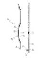
図6は、発光素子52を導光性シート56の端部に配置すると共に、端部以外の所定箇所にも適宜配置することで、光量のアップを図った構成のシートスイッチ51を示したものである。この実施形態のシートスイッチ51にあっては、FPC24上に実装されている発光素子52,53を収納するための凹部が設けられる。この凹部は、導光性シート56の端部に設けられる切欠き部54やこの端部以外の箇所に設けられる孔部55によって形成されている。前記切欠き部54に配置される発光素子52は、側面発光型の発光ダイオードが使用され、前記孔部55内に配置される発光素子53は、四方に均等に発光させるために上面発光型の発光ダイオードが使用される。また、前記切欠き部54や孔部55の内周面に透明樹脂31を充填することで、発光素子52,53との隙間を埋め、導光性シート56内への放射効率を高めることができる。さらに、前記発光素子52,53の高さに合わせて傾斜する入射部34を設けることで、発光素子52,53から出射された光を漏らさず導光性シート56内に導光させることができる。なお、その他の固定接点22、可動接点25、エンボス部29等の構造は、前記シートスイッチ21と同様であるので説明は省略する。 FIG. 6 shows a
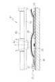
図7は、上記シートスイッチ21を組み込んだ操作パネル41の構成例を示したものである。この操作パネル41は、前記シートスイッチ21をマザーボード等の装置基板46上に両面粘着テープ42を介して接合し、上方には、透光性を有したラバーシート43と、透光性を有したキートップ44が所定箇所に複数設けられる表面シート45とによって構成したものである。 FIG. 7 shows a configuration example of the
前記ラバーシート43は、前記FPC24と略同じ大きさに形成され、そのうちの少なくともキートップ44に対応する部分が透明又は半透明に形成されている。また、前記可動接点25に対応する押圧部が僅かな厚みを持って形成されている。このラバーシート43は、押圧部が可動接点25の上端に接するように、前記シートスイッチ21と平行に配設される。なお、このラバーシート43を前記シートスイッチ21に安定して配設するために、両者間にスペーサ(図示せず)を挟んで高さ調整してもよい。 The
前記表面シート45は、このシートスイッチ21を搭載する電子機器の操作パネルの表示面を構成するものであり、一般にはゴム等の軟質性の樹脂材で形成され、前記可動接点25に対応する部分が肉厚のキートップ44となっている。この表面シート45は、前記ラバーシート43の上方を覆うようにして配置される。また、前記キートップ44は、透光性を有して形成され、その表面には各種の文字や記号等が印刷あるいは凹凸状に形成されている。前記キートップ44を除いた部分は、光を通さない遮光部材で形成される。また、前記遮光部材の裏面側に金属膜を形成することで、前記導光性シート26内での導光作用を高めることもできる。 The
前記シートスイッチ21の発光素子27から出射された光は、導光性シート26内の隅々に向けて導光される。前記可動接点25上に導光されてきた光は、可動接点25の金属面によって上方に向けて反射される。この可動接点25上で反射された光は、ラバーシート43を透過してキートップ44に入射され、このキートップ44の上面(操作面)を明るく照明することができる。上述したように、前記導光性シート26がドーム状に湾曲しているタクトバネの表面に密着しているため、このタクトバネ上に導光されてきた光は周囲に漏れることなく、大部分の光がキートップ44に向けて反射させることができ、高輝度で照明することができる。 The light emitted from the
本発明のシートスイッチ21は、FPC24をベースにして形成され、折り曲げ可能であると共に、導光性シート26が前記FPC24に密着して設けられているため、上記実施形態で示したような平面状の操作パネルに限らず、電子機器等の形状に合わせて曲面形状に形成された操作パネルにも搭載可能である。 The
21 シートスイッチ
22 固定接点
23 電極パターン
24 FPC
25 可動接点
26 導光性シート
27 発光素子
28 粘着剤
29 エンボス部
31 透明樹脂
32 立ち上がり部
33 外側側面
34 入射部
41 操作パネル
42 両面粘着テープ
43 ラバーシート
44 キートップ
45 表面シート
46 装置基板
21
DESCRIPTION OF
Claims (9)
Translated fromJapaneseこの回路基板上に配置される側面発光型の発光ダイオードと、
前記各固定接点の上方に被さるように配置されるドーム型の金属材で形成されたタクトバネと、
このタクトバネを前記回路基板上に被覆保持するシート材とを備え、
このシート材の上から前記タクトバネの上面を押圧することによって前記固定接点に導通してスイッチング回路を形成するシートスイッチモジュールであって、
前記シート材には、前記タクトバネを被覆保持する箇所に対応し且つ各タクトバネの形状に対応する形状からなるエンボス部が設けられると共に、該エンボス部の外周部にはタクトバネの外形形状に沿うような立ち上がり部が形成され、この立ち上がり部からタクトバネの上面に沿って前記発光ダイオードから出射される光を導光する導光性シートで構成されていることを特徴とするシートスイッチモジュール。A circuit board on which aplurality of fixed contacts are arranged;
Aside-emitting LED disposed on the circuit board;
And Takutobane formed of a metal material of a dome type, which is arranged so as to cover above thefixedcontacts,
A sheet materialfor covering and holding thetact spring on the circuit board;
A sheet switch module that forms a switching circuit by conducting to the fixed contact by pressingthe upper surface of thetact spring from above the sheet material,
It said sheet material,with embossed portions made of shape corresponding to the shape of the corresponding and respective Takutobane in place covering holds the Takutobane is provided, on the outer periphery of the embossed portions, such as along the outer shape of Takutobane A sheet switch module comprising a light guide sheet that has arising portion and guides light emitted from the lightemitting diode along the upper surface of atact spring from the rising portion .
Wherein the light guiding sheet is provided a recess for accommodating a light emittingdiode, sheet switch module according to claim 1, wherein closing the gap generated between the inner peripheral surface of the light emittingdiode and a recess housed in the recess in the transparent resin.
Priority Applications (5)
| Application Number | Priority Date | Filing Date | Title |
|---|---|---|---|
| JP2005239129AJP4728067B2 (en) | 2005-08-19 | 2005-08-19 | Seat switch module |
| TW095128441ATW200709243A (en) | 2005-08-19 | 2006-08-03 | Sheet switch, sheet switch module and panel switch |
| DE102006038025ADE102006038025A1 (en) | 2005-08-19 | 2006-08-14 | Foil switch, membrane switch module and built-in switch |
| US11/504,786US7994445B2 (en) | 2005-08-19 | 2006-08-16 | Sheet switch, sheet switch module and panel switch |
| CN2006101159538ACN1917113B (en) | 2005-08-19 | 2006-08-21 | Sheet switch, sheet switch module and panel switch |
Applications Claiming Priority (1)
| Application Number | Priority Date | Filing Date | Title |
|---|---|---|---|
| JP2005239129AJP4728067B2 (en) | 2005-08-19 | 2005-08-19 | Seat switch module |
Publications (2)
| Publication Number | Publication Date |
|---|---|
| JP2007053063A JP2007053063A (en) | 2007-03-01 |
| JP4728067B2true JP4728067B2 (en) | 2011-07-20 |
Family
ID=37738072
Family Applications (1)
| Application Number | Title | Priority Date | Filing Date |
|---|---|---|---|
| JP2005239129AExpired - LifetimeJP4728067B2 (en) | 2005-08-19 | 2005-08-19 | Seat switch module |
Country Status (2)
| Country | Link |
|---|---|
| JP (1) | JP4728067B2 (en) |
| CN (1) | CN1917113B (en) |
Families Citing this family (29)
| Publication number | Priority date | Publication date | Assignee | Title |
|---|---|---|---|---|
| JP2008234863A (en)* | 2007-03-16 | 2008-10-02 | Shin Etsu Polymer Co Ltd | Illuminating sheet structure and operation switch |
| KR20080088324A (en) | 2007-03-29 | 2008-10-02 | 삼성전자주식회사 | Keypad assembly |
| US7718910B2 (en) | 2007-06-20 | 2010-05-18 | Panasonic Corporation | Movable contact assembly and switch using the same |
| JP2009021142A (en) | 2007-07-13 | 2009-01-29 | Citizen Electronics Co Ltd | Sheet switch module |
| JP4190568B1 (en)* | 2007-07-30 | 2008-12-03 | シャープ株式会社 | Mobile device |
| JP2009037848A (en)* | 2007-08-01 | 2009-02-19 | Alps Electric Co Ltd | Illumination member for switch, and switch device using it |
| TWI345719B (en)* | 2007-11-15 | 2011-07-21 | Lite On Technology Corp | Light emitting keyboard |
| JP5239355B2 (en)* | 2007-11-22 | 2013-07-17 | パナソニック株式会社 | Manufacturing method of movable contact body |
| US7946720B2 (en) | 2007-11-22 | 2011-05-24 | Panasonic Corporation | Light guide sheet, movable contact structure using the light guide sheet, method of manufacturing the movable contact structure, and switch using the light guide sheet and the movable contact structure |
| CN101452781B (en)* | 2007-12-06 | 2011-07-20 | 旭丽电子(广州)有限公司 | Push button device |
| JP5298819B2 (en)* | 2007-12-11 | 2013-09-25 | パナソニック株式会社 | Movable contact body with light guiding function and illumination panel switch constructed using the same |
| JP5293068B2 (en)* | 2008-01-07 | 2013-09-18 | パナソニック株式会社 | Movable contact body |
| JP2009205940A (en)* | 2008-02-28 | 2009-09-10 | Panasonic Corp | Light guide sheet, and moving contact body using it |
| JP2009245909A (en)* | 2008-04-01 | 2009-10-22 | Omron Corp | Key illumination switch module, and light guide sheet |
| JP2009283174A (en)* | 2008-05-20 | 2009-12-03 | Shin Etsu Polymer Co Ltd | Illumination structure equipped with light guide layer |
| WO2009157218A1 (en) | 2008-06-26 | 2009-12-30 | 日本メクトロン株式会社 | Key module of portable apparatus |
| JP2010027537A (en)* | 2008-07-24 | 2010-02-04 | Citizen Electronics Co Ltd | Sheet switch module |
| TW201044435A (en)* | 2009-03-31 | 2010-12-16 | Fujikura Ltd | Sheet switch module and manufacturing method thereof |
| JP5466916B2 (en) | 2009-10-15 | 2014-04-09 | 日本メクトロン株式会社 | Switch module |
| FI20096108A7 (en)* | 2009-10-28 | 2011-04-29 | Perlos Oyj | Arrangement |
| JP5427638B2 (en)* | 2010-02-17 | 2014-02-26 | 日本メクトロン株式会社 | Switch module |
| JP5427637B2 (en)* | 2010-02-17 | 2014-02-26 | 日本メクトロン株式会社 | Switch module |
| JP2011222379A (en)* | 2010-04-13 | 2011-11-04 | Alps Electric Co Ltd | Light guide sheet, sheet with contact spring, and switch device |
| TW201140634A (en)* | 2010-05-07 | 2011-11-16 | Primax Electronics Ltd | Luminous keyboard |
| KR101102943B1 (en)* | 2011-07-27 | 2012-01-10 | 박철종 | Waveguide with integrated dome switch |
| CN102853376B (en)* | 2012-08-01 | 2015-10-28 | 惠州Tcl移动通信有限公司 | A kind of leaded light component of screen soft keyboard character and touch-screen mobile phone |
| JP6945186B2 (en)* | 2017-07-10 | 2021-10-06 | パナソニックIpマネジメント株式会社 | Lighting device |
| CN107845521B (en)* | 2017-11-27 | 2020-03-24 | 维沃移动通信有限公司 | Electronic equipment and key lamp |
| CN113661553A (en)* | 2019-04-10 | 2021-11-16 | 松下知识产权经营株式会社 | Key switch and lighting switch device |
Family Cites Families (11)
| Publication number | Priority date | Publication date | Assignee | Title |
|---|---|---|---|---|
| JPH06275169A (en)* | 1993-03-18 | 1994-09-30 | Fujitsu Ltd | Keyboard switch |
| US5613751A (en)* | 1995-06-27 | 1997-03-25 | Lumitex, Inc. | Light emitting panel assemblies |
| JPH1139983A (en)* | 1997-07-14 | 1999-02-12 | Teikoku Tsushin Kogyo Co Ltd | EL illuminated sheet and EL illuminated switch |
| JPH11345532A (en)* | 1998-06-02 | 1999-12-14 | Shin Etsu Polymer Co Ltd | Illuminated pushbutton switch device |
| JP2001155586A (en)* | 1999-11-26 | 2001-06-08 | Shin Etsu Polymer Co Ltd | Push button switch device |
| FI108582B (en)* | 2000-05-02 | 2002-02-15 | Nokia Corp | Keyboard lighting arrangements that allow dynamic and individual lighting of keys, as well as method of utilizing it |
| JP2003100131A (en)* | 2001-09-19 | 2003-04-04 | Matsushita Electric Ind Co Ltd | Surface emitting device |
| JP4080271B2 (en)* | 2002-08-01 | 2008-04-23 | シチズン電子株式会社 | Light guide sheet and key switch incorporating the same |
| JP2004171966A (en)* | 2002-11-21 | 2004-06-17 | Matsushita Electric Ind Co Ltd | Surface lighting device |
| KR100689392B1 (en)* | 2005-05-19 | 2007-03-02 | 삼성전자주식회사 | Keypad and Keypad Assembly Using the Keypad |
| KR100629053B1 (en)* | 2005-05-19 | 2006-09-26 | 삼성전자주식회사 | Key pad assembly |
- 2005
- 2005-08-19JPJP2005239129Apatent/JP4728067B2/ennot_activeExpired - Lifetime
- 2006
- 2006-08-21CNCN2006101159538Apatent/CN1917113B/ennot_activeExpired - Fee Related
Also Published As
| Publication number | Publication date |
|---|---|
| CN1917113B (en) | 2011-07-06 |
| JP2007053063A (en) | 2007-03-01 |
| CN1917113A (en) | 2007-02-21 |
Similar Documents
| Publication | Publication Date | Title |
|---|---|---|
| JP4728067B2 (en) | Seat switch module | |
| JP4926762B2 (en) | Luminescent sheet module | |
| JP4917840B2 (en) | Seat switch module | |
| JP4959164B2 (en) | Seat switch, seat switch module and panel switch | |
| JP4845701B2 (en) | Seat switch module | |
| CN210129448U (en) | Key structure and luminous keyboard | |
| US7994445B2 (en) | Sheet switch, sheet switch module and panel switch | |
| US7651231B2 (en) | Lighting module for use in a keypad device | |
| JP2009021142A (en) | Sheet switch module | |
| KR200424232Y1 (en) | Mobile phone keypad light emitting assembly using light guide plate | |
| TWM528464U (en) | Lighting input device | |
| JPWO2007097117A1 (en) | Side light emitting unit and illumination panel | |
| JP2010015794A (en) | Light guide sheet switch unit | |
| CN104252988A (en) | Illuminated keyboard device | |
| JPWO2008072666A1 (en) | Illuminated input device | |
| TWM486089U (en) | Light emitting keyboard and light emitting structure thereof | |
| JP5136934B2 (en) | Flexible printed wiring board, input module and portable device | |
| JP2005268165A (en) | Lighted key switch | |
| JP5204018B2 (en) | Keyboard device having illumination function | |
| JP2010034008A (en) | Light guide sheet switch unit | |
| KR20070021964A (en) | Seat Switches, Seat Switch Modules & Panel Switches | |
| CN113759595A (en) | Backlight structure and display device | |
| JP7641425B1 (en) | Keyboard device and electronic device | |
| JP4959415B2 (en) | Light guide key sheet and light guide key sheet module | |
| CN205101908U (en) | A thin light emitting module |
Legal Events
| Date | Code | Title | Description |
|---|---|---|---|
| A621 | Written request for application examination | Free format text:JAPANESE INTERMEDIATE CODE: A621 Effective date:20080718 | |
| A977 | Report on retrieval | Free format text:JAPANESE INTERMEDIATE CODE: A971007 Effective date:20100914 | |
| A131 | Notification of reasons for refusal | Free format text:JAPANESE INTERMEDIATE CODE: A131 Effective date:20101221 | |
| A521 | Request for written amendment filed | Free format text:JAPANESE INTERMEDIATE CODE: A523 Effective date:20110218 | |
| A131 | Notification of reasons for refusal | Free format text:JAPANESE INTERMEDIATE CODE: A131 Effective date:20110322 | |
| A521 | Request for written amendment filed | Free format text:JAPANESE INTERMEDIATE CODE: A523 Effective date:20110324 | |
| TRDD | Decision of grant or rejection written | ||
| A01 | Written decision to grant a patent or to grant a registration (utility model) | Free format text:JAPANESE INTERMEDIATE CODE: A01 Effective date:20110412 | |
| A01 | Written decision to grant a patent or to grant a registration (utility model) | Free format text:JAPANESE INTERMEDIATE CODE: A01 | |
| A61 | First payment of annual fees (during grant procedure) | Free format text:JAPANESE INTERMEDIATE CODE: A61 Effective date:20110414 | |
| R150 | Certificate of patent or registration of utility model | Free format text:JAPANESE INTERMEDIATE CODE: R150 | |
| FPAY | Renewal fee payment (event date is renewal date of database) | Free format text:PAYMENT UNTIL: 20140422 Year of fee payment:3 | |
| R250 | Receipt of annual fees | Free format text:JAPANESE INTERMEDIATE CODE: R250 | |
| R250 | Receipt of annual fees | Free format text:JAPANESE INTERMEDIATE CODE: R250 |