JP4726939B2 - Control system, control device, and cable connection state determination method - Google Patents
Control system, control device, and cable connection state determination methodDownload PDFInfo
- Publication number
- JP4726939B2 JP4726939B2JP2008247793AJP2008247793AJP4726939B2JP 4726939 B2JP4726939 B2JP 4726939B2JP 2008247793 AJP2008247793 AJP 2008247793AJP 2008247793 AJP2008247793 AJP 2008247793AJP 4726939 B2JP4726939 B2JP 4726939B2
- Authority
- JP
- Japan
- Prior art keywords
- vehicle
- connector
- signal line
- power
- signal
- Prior art date
- Legal status (The legal status is an assumption and is not a legal conclusion. Google has not performed a legal analysis and makes no representation as to the accuracy of the status listed.)
- Active
Links
Images


Classifications
- B—PERFORMING OPERATIONS; TRANSPORTING
- B60—VEHICLES IN GENERAL
- B60L—PROPULSION OF ELECTRICALLY-PROPELLED VEHICLES; SUPPLYING ELECTRIC POWER FOR AUXILIARY EQUIPMENT OF ELECTRICALLY-PROPELLED VEHICLES; ELECTRODYNAMIC BRAKE SYSTEMS FOR VEHICLES IN GENERAL; MAGNETIC SUSPENSION OR LEVITATION FOR VEHICLES; MONITORING OPERATING VARIABLES OF ELECTRICALLY-PROPELLED VEHICLES; ELECTRIC SAFETY DEVICES FOR ELECTRICALLY-PROPELLED VEHICLES
- B60L53/00—Methods of charging batteries, specially adapted for electric vehicles; Charging stations or on-board charging equipment therefor; Exchange of energy storage elements in electric vehicles
- B60L53/10—Methods of charging batteries, specially adapted for electric vehicles; Charging stations or on-board charging equipment therefor; Exchange of energy storage elements in electric vehicles characterised by the energy transfer between the charging station and the vehicle
- B60L53/14—Conductive energy transfer
- B—PERFORMING OPERATIONS; TRANSPORTING
- B60—VEHICLES IN GENERAL
- B60K—ARRANGEMENT OR MOUNTING OF PROPULSION UNITS OR OF TRANSMISSIONS IN VEHICLES; ARRANGEMENT OR MOUNTING OF PLURAL DIVERSE PRIME-MOVERS IN VEHICLES; AUXILIARY DRIVES FOR VEHICLES; INSTRUMENTATION OR DASHBOARDS FOR VEHICLES; ARRANGEMENTS IN CONNECTION WITH COOLING, AIR INTAKE, GAS EXHAUST OR FUEL SUPPLY OF PROPULSION UNITS IN VEHICLES
- B60K6/00—Arrangement or mounting of plural diverse prime-movers for mutual or common propulsion, e.g. hybrid propulsion systems comprising electric motors and internal combustion engines
- B60K6/20—Arrangement or mounting of plural diverse prime-movers for mutual or common propulsion, e.g. hybrid propulsion systems comprising electric motors and internal combustion engines the prime-movers consisting of electric motors and internal combustion engines, e.g. HEVs
- B60K6/22—Arrangement or mounting of plural diverse prime-movers for mutual or common propulsion, e.g. hybrid propulsion systems comprising electric motors and internal combustion engines the prime-movers consisting of electric motors and internal combustion engines, e.g. HEVs characterised by apparatus, components or means specially adapted for HEVs
- B60K6/36—Arrangement or mounting of plural diverse prime-movers for mutual or common propulsion, e.g. hybrid propulsion systems comprising electric motors and internal combustion engines the prime-movers consisting of electric motors and internal combustion engines, e.g. HEVs characterised by apparatus, components or means specially adapted for HEVs characterised by the transmission gearings
- B60K6/365—Arrangement or mounting of plural diverse prime-movers for mutual or common propulsion, e.g. hybrid propulsion systems comprising electric motors and internal combustion engines the prime-movers consisting of electric motors and internal combustion engines, e.g. HEVs characterised by apparatus, components or means specially adapted for HEVs characterised by the transmission gearings with the gears having orbital motion
- B—PERFORMING OPERATIONS; TRANSPORTING
- B60—VEHICLES IN GENERAL
- B60K—ARRANGEMENT OR MOUNTING OF PROPULSION UNITS OR OF TRANSMISSIONS IN VEHICLES; ARRANGEMENT OR MOUNTING OF PLURAL DIVERSE PRIME-MOVERS IN VEHICLES; AUXILIARY DRIVES FOR VEHICLES; INSTRUMENTATION OR DASHBOARDS FOR VEHICLES; ARRANGEMENTS IN CONNECTION WITH COOLING, AIR INTAKE, GAS EXHAUST OR FUEL SUPPLY OF PROPULSION UNITS IN VEHICLES
- B60K6/00—Arrangement or mounting of plural diverse prime-movers for mutual or common propulsion, e.g. hybrid propulsion systems comprising electric motors and internal combustion engines
- B60K6/20—Arrangement or mounting of plural diverse prime-movers for mutual or common propulsion, e.g. hybrid propulsion systems comprising electric motors and internal combustion engines the prime-movers consisting of electric motors and internal combustion engines, e.g. HEVs
- B60K6/42—Arrangement or mounting of plural diverse prime-movers for mutual or common propulsion, e.g. hybrid propulsion systems comprising electric motors and internal combustion engines the prime-movers consisting of electric motors and internal combustion engines, e.g. HEVs characterised by the architecture of the hybrid electric vehicle
- B60K6/44—Series-parallel type
- B60K6/445—Differential gearing distribution type
- B—PERFORMING OPERATIONS; TRANSPORTING
- B60—VEHICLES IN GENERAL
- B60L—PROPULSION OF ELECTRICALLY-PROPELLED VEHICLES; SUPPLYING ELECTRIC POWER FOR AUXILIARY EQUIPMENT OF ELECTRICALLY-PROPELLED VEHICLES; ELECTRODYNAMIC BRAKE SYSTEMS FOR VEHICLES IN GENERAL; MAGNETIC SUSPENSION OR LEVITATION FOR VEHICLES; MONITORING OPERATING VARIABLES OF ELECTRICALLY-PROPELLED VEHICLES; ELECTRIC SAFETY DEVICES FOR ELECTRICALLY-PROPELLED VEHICLES
- B60L15/00—Methods, circuits, or devices for controlling the traction-motor speed of electrically-propelled vehicles
- B60L15/007—Physical arrangements or structures of drive train converters specially adapted for the propulsion motors of electric vehicles
- B—PERFORMING OPERATIONS; TRANSPORTING
- B60—VEHICLES IN GENERAL
- B60L—PROPULSION OF ELECTRICALLY-PROPELLED VEHICLES; SUPPLYING ELECTRIC POWER FOR AUXILIARY EQUIPMENT OF ELECTRICALLY-PROPELLED VEHICLES; ELECTRODYNAMIC BRAKE SYSTEMS FOR VEHICLES IN GENERAL; MAGNETIC SUSPENSION OR LEVITATION FOR VEHICLES; MONITORING OPERATING VARIABLES OF ELECTRICALLY-PROPELLED VEHICLES; ELECTRIC SAFETY DEVICES FOR ELECTRICALLY-PROPELLED VEHICLES
- B60L50/00—Electric propulsion with power supplied within the vehicle
- B60L50/10—Electric propulsion with power supplied within the vehicle using propulsion power supplied by engine-driven generators, e.g. generators driven by combustion engines
- B60L50/16—Electric propulsion with power supplied within the vehicle using propulsion power supplied by engine-driven generators, e.g. generators driven by combustion engines with provision for separate direct mechanical propulsion
- B—PERFORMING OPERATIONS; TRANSPORTING
- B60—VEHICLES IN GENERAL
- B60L—PROPULSION OF ELECTRICALLY-PROPELLED VEHICLES; SUPPLYING ELECTRIC POWER FOR AUXILIARY EQUIPMENT OF ELECTRICALLY-PROPELLED VEHICLES; ELECTRODYNAMIC BRAKE SYSTEMS FOR VEHICLES IN GENERAL; MAGNETIC SUSPENSION OR LEVITATION FOR VEHICLES; MONITORING OPERATING VARIABLES OF ELECTRICALLY-PROPELLED VEHICLES; ELECTRIC SAFETY DEVICES FOR ELECTRICALLY-PROPELLED VEHICLES
- B60L50/00—Electric propulsion with power supplied within the vehicle
- B60L50/50—Electric propulsion with power supplied within the vehicle using propulsion power supplied by batteries or fuel cells
- B60L50/60—Electric propulsion with power supplied within the vehicle using propulsion power supplied by batteries or fuel cells using power supplied by batteries
- B60L50/61—Electric propulsion with power supplied within the vehicle using propulsion power supplied by batteries or fuel cells using power supplied by batteries by batteries charged by engine-driven generators, e.g. series hybrid electric vehicles
- B—PERFORMING OPERATIONS; TRANSPORTING
- B60—VEHICLES IN GENERAL
- B60L—PROPULSION OF ELECTRICALLY-PROPELLED VEHICLES; SUPPLYING ELECTRIC POWER FOR AUXILIARY EQUIPMENT OF ELECTRICALLY-PROPELLED VEHICLES; ELECTRODYNAMIC BRAKE SYSTEMS FOR VEHICLES IN GENERAL; MAGNETIC SUSPENSION OR LEVITATION FOR VEHICLES; MONITORING OPERATING VARIABLES OF ELECTRICALLY-PROPELLED VEHICLES; ELECTRIC SAFETY DEVICES FOR ELECTRICALLY-PROPELLED VEHICLES
- B60L53/00—Methods of charging batteries, specially adapted for electric vehicles; Charging stations or on-board charging equipment therefor; Exchange of energy storage elements in electric vehicles
- B60L53/10—Methods of charging batteries, specially adapted for electric vehicles; Charging stations or on-board charging equipment therefor; Exchange of energy storage elements in electric vehicles characterised by the energy transfer between the charging station and the vehicle
- B60L53/14—Conductive energy transfer
- B60L53/18—Cables specially adapted for charging electric vehicles
- B—PERFORMING OPERATIONS; TRANSPORTING
- B60—VEHICLES IN GENERAL
- B60L—PROPULSION OF ELECTRICALLY-PROPELLED VEHICLES; SUPPLYING ELECTRIC POWER FOR AUXILIARY EQUIPMENT OF ELECTRICALLY-PROPELLED VEHICLES; ELECTRODYNAMIC BRAKE SYSTEMS FOR VEHICLES IN GENERAL; MAGNETIC SUSPENSION OR LEVITATION FOR VEHICLES; MONITORING OPERATING VARIABLES OF ELECTRICALLY-PROPELLED VEHICLES; ELECTRIC SAFETY DEVICES FOR ELECTRICALLY-PROPELLED VEHICLES
- B60L53/00—Methods of charging batteries, specially adapted for electric vehicles; Charging stations or on-board charging equipment therefor; Exchange of energy storage elements in electric vehicles
- B60L53/20—Methods of charging batteries, specially adapted for electric vehicles; Charging stations or on-board charging equipment therefor; Exchange of energy storage elements in electric vehicles characterised by converters located in the vehicle
- B60L53/22—Constructional details or arrangements of charging converters specially adapted for charging electric vehicles
- B—PERFORMING OPERATIONS; TRANSPORTING
- B60—VEHICLES IN GENERAL
- B60W—CONJOINT CONTROL OF VEHICLE SUB-UNITS OF DIFFERENT TYPE OR DIFFERENT FUNCTION; CONTROL SYSTEMS SPECIALLY ADAPTED FOR HYBRID VEHICLES; ROAD VEHICLE DRIVE CONTROL SYSTEMS FOR PURPOSES NOT RELATED TO THE CONTROL OF A PARTICULAR SUB-UNIT
- B60W10/00—Conjoint control of vehicle sub-units of different type or different function
- B60W10/24—Conjoint control of vehicle sub-units of different type or different function including control of energy storage means
- B60W10/26—Conjoint control of vehicle sub-units of different type or different function including control of energy storage means for electrical energy, e.g. batteries or capacitors
- B—PERFORMING OPERATIONS; TRANSPORTING
- B60—VEHICLES IN GENERAL
- B60W—CONJOINT CONTROL OF VEHICLE SUB-UNITS OF DIFFERENT TYPE OR DIFFERENT FUNCTION; CONTROL SYSTEMS SPECIALLY ADAPTED FOR HYBRID VEHICLES; ROAD VEHICLE DRIVE CONTROL SYSTEMS FOR PURPOSES NOT RELATED TO THE CONTROL OF A PARTICULAR SUB-UNIT
- B60W20/00—Control systems specially adapted for hybrid vehicles
- B60W20/10—Controlling the power contribution of each of the prime movers to meet required power demand
- B60W20/13—Controlling the power contribution of each of the prime movers to meet required power demand in order to stay within battery power input or output limits; in order to prevent overcharging or battery depletion
- B—PERFORMING OPERATIONS; TRANSPORTING
- B60—VEHICLES IN GENERAL
- B60K—ARRANGEMENT OR MOUNTING OF PROPULSION UNITS OR OF TRANSMISSIONS IN VEHICLES; ARRANGEMENT OR MOUNTING OF PLURAL DIVERSE PRIME-MOVERS IN VEHICLES; AUXILIARY DRIVES FOR VEHICLES; INSTRUMENTATION OR DASHBOARDS FOR VEHICLES; ARRANGEMENTS IN CONNECTION WITH COOLING, AIR INTAKE, GAS EXHAUST OR FUEL SUPPLY OF PROPULSION UNITS IN VEHICLES
- B60K1/00—Arrangement or mounting of electrical propulsion units
- B60K1/02—Arrangement or mounting of electrical propulsion units comprising more than one electric motor
- B—PERFORMING OPERATIONS; TRANSPORTING
- B60—VEHICLES IN GENERAL
- B60L—PROPULSION OF ELECTRICALLY-PROPELLED VEHICLES; SUPPLYING ELECTRIC POWER FOR AUXILIARY EQUIPMENT OF ELECTRICALLY-PROPELLED VEHICLES; ELECTRODYNAMIC BRAKE SYSTEMS FOR VEHICLES IN GENERAL; MAGNETIC SUSPENSION OR LEVITATION FOR VEHICLES; MONITORING OPERATING VARIABLES OF ELECTRICALLY-PROPELLED VEHICLES; ELECTRIC SAFETY DEVICES FOR ELECTRICALLY-PROPELLED VEHICLES
- B60L2270/00—Problem solutions or means not otherwise provided for
- B60L2270/30—Preventing theft during charging
- B60L2270/36—Preventing theft during charging of vehicles
- B—PERFORMING OPERATIONS; TRANSPORTING
- B60—VEHICLES IN GENERAL
- B60W—CONJOINT CONTROL OF VEHICLE SUB-UNITS OF DIFFERENT TYPE OR DIFFERENT FUNCTION; CONTROL SYSTEMS SPECIALLY ADAPTED FOR HYBRID VEHICLES; ROAD VEHICLE DRIVE CONTROL SYSTEMS FOR PURPOSES NOT RELATED TO THE CONTROL OF A PARTICULAR SUB-UNIT
- B60W20/00—Control systems specially adapted for hybrid vehicles
- B—PERFORMING OPERATIONS; TRANSPORTING
- B60—VEHICLES IN GENERAL
- B60W—CONJOINT CONTROL OF VEHICLE SUB-UNITS OF DIFFERENT TYPE OR DIFFERENT FUNCTION; CONTROL SYSTEMS SPECIALLY ADAPTED FOR HYBRID VEHICLES; ROAD VEHICLE DRIVE CONTROL SYSTEMS FOR PURPOSES NOT RELATED TO THE CONTROL OF A PARTICULAR SUB-UNIT
- B60W50/00—Details of control systems for road vehicle drive control not related to the control of a particular sub-unit, e.g. process diagnostic or vehicle driver interfaces
- B60W50/08—Interaction between the driver and the control system
- B60W50/14—Means for informing the driver, warning the driver or prompting a driver intervention
- B60W2050/143—Alarm means
- B—PERFORMING OPERATIONS; TRANSPORTING
- B60—VEHICLES IN GENERAL
- B60W—CONJOINT CONTROL OF VEHICLE SUB-UNITS OF DIFFERENT TYPE OR DIFFERENT FUNCTION; CONTROL SYSTEMS SPECIALLY ADAPTED FOR HYBRID VEHICLES; ROAD VEHICLE DRIVE CONTROL SYSTEMS FOR PURPOSES NOT RELATED TO THE CONTROL OF A PARTICULAR SUB-UNIT
- B60W50/00—Details of control systems for road vehicle drive control not related to the control of a particular sub-unit, e.g. process diagnostic or vehicle driver interfaces
- B60W50/08—Interaction between the driver and the control system
- B60W50/14—Means for informing the driver, warning the driver or prompting a driver intervention
- B60W2050/146—Display means
- B—PERFORMING OPERATIONS; TRANSPORTING
- B60—VEHICLES IN GENERAL
- B60W—CONJOINT CONTROL OF VEHICLE SUB-UNITS OF DIFFERENT TYPE OR DIFFERENT FUNCTION; CONTROL SYSTEMS SPECIALLY ADAPTED FOR HYBRID VEHICLES; ROAD VEHICLE DRIVE CONTROL SYSTEMS FOR PURPOSES NOT RELATED TO THE CONTROL OF A PARTICULAR SUB-UNIT
- B60W2520/00—Input parameters relating to overall vehicle dynamics
- B60W2520/10—Longitudinal speed
- B—PERFORMING OPERATIONS; TRANSPORTING
- B60—VEHICLES IN GENERAL
- B60W—CONJOINT CONTROL OF VEHICLE SUB-UNITS OF DIFFERENT TYPE OR DIFFERENT FUNCTION; CONTROL SYSTEMS SPECIALLY ADAPTED FOR HYBRID VEHICLES; ROAD VEHICLE DRIVE CONTROL SYSTEMS FOR PURPOSES NOT RELATED TO THE CONTROL OF A PARTICULAR SUB-UNIT
- B60W2710/00—Output or target parameters relating to a particular sub-units
- B60W2710/30—Auxiliary equipments
- B60W2710/305—Auxiliary equipments target power to auxiliaries
- Y—GENERAL TAGGING OF NEW TECHNOLOGICAL DEVELOPMENTS; GENERAL TAGGING OF CROSS-SECTIONAL TECHNOLOGIES SPANNING OVER SEVERAL SECTIONS OF THE IPC; TECHNICAL SUBJECTS COVERED BY FORMER USPC CROSS-REFERENCE ART COLLECTIONS [XRACs] AND DIGESTS
- Y02—TECHNOLOGIES OR APPLICATIONS FOR MITIGATION OR ADAPTATION AGAINST CLIMATE CHANGE
- Y02T—CLIMATE CHANGE MITIGATION TECHNOLOGIES RELATED TO TRANSPORTATION
- Y02T10/00—Road transport of goods or passengers
- Y02T10/60—Other road transportation technologies with climate change mitigation effect
- Y02T10/62—Hybrid vehicles
- Y—GENERAL TAGGING OF NEW TECHNOLOGICAL DEVELOPMENTS; GENERAL TAGGING OF CROSS-SECTIONAL TECHNOLOGIES SPANNING OVER SEVERAL SECTIONS OF THE IPC; TECHNICAL SUBJECTS COVERED BY FORMER USPC CROSS-REFERENCE ART COLLECTIONS [XRACs] AND DIGESTS
- Y02—TECHNOLOGIES OR APPLICATIONS FOR MITIGATION OR ADAPTATION AGAINST CLIMATE CHANGE
- Y02T—CLIMATE CHANGE MITIGATION TECHNOLOGIES RELATED TO TRANSPORTATION
- Y02T10/00—Road transport of goods or passengers
- Y02T10/60—Other road transportation technologies with climate change mitigation effect
- Y02T10/64—Electric machine technologies in electromobility
- Y—GENERAL TAGGING OF NEW TECHNOLOGICAL DEVELOPMENTS; GENERAL TAGGING OF CROSS-SECTIONAL TECHNOLOGIES SPANNING OVER SEVERAL SECTIONS OF THE IPC; TECHNICAL SUBJECTS COVERED BY FORMER USPC CROSS-REFERENCE ART COLLECTIONS [XRACs] AND DIGESTS
- Y02—TECHNOLOGIES OR APPLICATIONS FOR MITIGATION OR ADAPTATION AGAINST CLIMATE CHANGE
- Y02T—CLIMATE CHANGE MITIGATION TECHNOLOGIES RELATED TO TRANSPORTATION
- Y02T10/00—Road transport of goods or passengers
- Y02T10/60—Other road transportation technologies with climate change mitigation effect
- Y02T10/70—Energy storage systems for electromobility, e.g. batteries
- Y—GENERAL TAGGING OF NEW TECHNOLOGICAL DEVELOPMENTS; GENERAL TAGGING OF CROSS-SECTIONAL TECHNOLOGIES SPANNING OVER SEVERAL SECTIONS OF THE IPC; TECHNICAL SUBJECTS COVERED BY FORMER USPC CROSS-REFERENCE ART COLLECTIONS [XRACs] AND DIGESTS
- Y02—TECHNOLOGIES OR APPLICATIONS FOR MITIGATION OR ADAPTATION AGAINST CLIMATE CHANGE
- Y02T—CLIMATE CHANGE MITIGATION TECHNOLOGIES RELATED TO TRANSPORTATION
- Y02T10/00—Road transport of goods or passengers
- Y02T10/60—Other road transportation technologies with climate change mitigation effect
- Y02T10/7072—Electromobility specific charging systems or methods for batteries, ultracapacitors, supercapacitors or double-layer capacitors
- Y—GENERAL TAGGING OF NEW TECHNOLOGICAL DEVELOPMENTS; GENERAL TAGGING OF CROSS-SECTIONAL TECHNOLOGIES SPANNING OVER SEVERAL SECTIONS OF THE IPC; TECHNICAL SUBJECTS COVERED BY FORMER USPC CROSS-REFERENCE ART COLLECTIONS [XRACs] AND DIGESTS
- Y02—TECHNOLOGIES OR APPLICATIONS FOR MITIGATION OR ADAPTATION AGAINST CLIMATE CHANGE
- Y02T—CLIMATE CHANGE MITIGATION TECHNOLOGIES RELATED TO TRANSPORTATION
- Y02T90/00—Enabling technologies or technologies with a potential or indirect contribution to GHG emissions mitigation
- Y02T90/10—Technologies relating to charging of electric vehicles
- Y02T90/12—Electric charging stations
- Y—GENERAL TAGGING OF NEW TECHNOLOGICAL DEVELOPMENTS; GENERAL TAGGING OF CROSS-SECTIONAL TECHNOLOGIES SPANNING OVER SEVERAL SECTIONS OF THE IPC; TECHNICAL SUBJECTS COVERED BY FORMER USPC CROSS-REFERENCE ART COLLECTIONS [XRACs] AND DIGESTS
- Y02—TECHNOLOGIES OR APPLICATIONS FOR MITIGATION OR ADAPTATION AGAINST CLIMATE CHANGE
- Y02T—CLIMATE CHANGE MITIGATION TECHNOLOGIES RELATED TO TRANSPORTATION
- Y02T90/00—Enabling technologies or technologies with a potential or indirect contribution to GHG emissions mitigation
- Y02T90/10—Technologies relating to charging of electric vehicles
- Y02T90/14—Plug-in electric vehicles
- Y—GENERAL TAGGING OF NEW TECHNOLOGICAL DEVELOPMENTS; GENERAL TAGGING OF CROSS-SECTIONAL TECHNOLOGIES SPANNING OVER SEVERAL SECTIONS OF THE IPC; TECHNICAL SUBJECTS COVERED BY FORMER USPC CROSS-REFERENCE ART COLLECTIONS [XRACs] AND DIGESTS
- Y02—TECHNOLOGIES OR APPLICATIONS FOR MITIGATION OR ADAPTATION AGAINST CLIMATE CHANGE
- Y02T—CLIMATE CHANGE MITIGATION TECHNOLOGIES RELATED TO TRANSPORTATION
- Y02T90/00—Enabling technologies or technologies with a potential or indirect contribution to GHG emissions mitigation
- Y02T90/10—Technologies relating to charging of electric vehicles
- Y02T90/16—Information or communication technologies improving the operation of electric vehicles
Landscapes
- Engineering & Computer Science (AREA)
- Transportation (AREA)
- Mechanical Engineering (AREA)
- Power Engineering (AREA)
- Chemical & Material Sciences (AREA)
- Combustion & Propulsion (AREA)
- Life Sciences & Earth Sciences (AREA)
- Sustainable Development (AREA)
- Sustainable Energy (AREA)
- Automation & Control Theory (AREA)
- Electric Propulsion And Braking For Vehicles (AREA)
- Details Of Connecting Devices For Male And Female Coupling (AREA)
Description
Translated fromJapanese本発明は、車両に搭載された車両駆動用の蓄電装置を充電するための制御システム、制御装置、及びケーブル接続状態判定方法に関する。 The present invention relates to a control system, a control device, and a cable connection state determination method for charging a power storage device for driving a vehicle mounted on a vehicle.
環境に配慮した車両として、電気自動車やハイブリッド車、燃料電池車などが近年注目されている。これらの車両には、走行駆動力を発生する電動機と、その電動機に供給される電力を蓄える蓄電装置とが搭載されている。ハイブリッド車には、動力源として電動機とともに内燃機関がさらに搭載され、燃料電池車には、車両駆動用の直流電源として燃料電池が搭載されている。 In recent years, electric vehicles, hybrid vehicles, fuel cell vehicles, and the like have attracted attention as environmentally friendly vehicles. These vehicles are equipped with an electric motor that generates a driving force and a power storage device that stores electric power supplied to the electric motor. The hybrid vehicle further includes an internal combustion engine as an electric power source as a power source, and the fuel cell vehicle includes a fuel cell as a DC power source for driving the vehicle.
このような車両に搭載された車両駆動用の蓄電装置を、一般家庭の電源から直接充電することが可能な車両が知られている。例えば、家屋に設けられた商用電源のコンセントと車両に設けられた充電口とを充電ケーブルで接続することにより、一般家庭の電源から蓄電装置へ電力が供給される。このように車両外部の電源から車両に搭載された蓄電装置を直接充電することが可能な車両を「プラグイン車」と称する。 2. Description of the Related Art A vehicle that can directly charge a power storage device for driving a vehicle mounted on such a vehicle from a power source of a general household is known. For example, by connecting a commercial power outlet provided in a house and a charging port provided in a vehicle with a charging cable, power is supplied from a general household power source to the power storage device. A vehicle that can directly charge a power storage device mounted on the vehicle from a power source outside the vehicle is referred to as a “plug-in vehicle”.
プラグイン車の規格は、アメリカ合衆国では「エスエーイー エレクトリック ビークル コンダクティブ チャージ カプラ」(非特許文献1)により制定され、日本では「電気自動車用コンダクティブ充電システム一般要求事項」(非特許文献2)により制定されている。 The standard for plug-in vehicles is established in the United States by “SA Electric Vehicle Conductive Charge Coupler” (Non-Patent Document 1), and in Japan by “General Requirements for Conductive Charging Systems for Electric Vehicles” (Non-Patent Document 2). Yes.
「エスエーイー エレクトリック ビークル コンダクティブ チャージ カプラ」及び「電気自動車用コンダクティブ充電システム一般要求事項」では、一例として、コントロールパイロットに関する規格が定められている。コントロールパイロットは、構内配線から車両へ電力を供給するEVSE(Electric Vehicle Supply Equipment)の制御回路と車両の接地部とを車両側の制御回路を介して接続する制御線と定義されており、この制御線を介して通信されるパイロット信号に基づいて、充電ケーブルの接続状態や電源から車両への電力供給の可否、EVSEの定格電流などが判断される。
しかしながら、「エスエーイー エレクトリック ビークル コンダクティブ チャージ カプラ」や「電気自動車用コンダクティブ充電システム一般要求事項」では、パイロット信号が通信される制御線の断線を検出する手法の詳細については特に制定されていない。 However, the “SA Electric Vehicle Conductive Charge Coupler” and “Conductive Charging System General Requirements for Electric Vehicles” do not specifically define the method for detecting the disconnection of the control line through which the pilot signal is communicated.
例えば、単に制御線の電位が接地レベルであるというだけでは、制御線の断線なのか、電源が停電しているのか、それとも充電ケーブルがコンセントから抜けているのか等を区別することはできない。 For example, simply because the potential of the control line is at the ground level, it is not possible to distinguish whether the control line is disconnected, whether the power source is out of power, or whether the charging cable is disconnected from the outlet.
そのため、充電ケーブルが接続されていても、蓄電装置への充電が行なわれない場合には、蓄電装置が放電状態になるまでユーザが気付かないという問題があり、ハイブリッド車両ではガソリン等の燃料でのみの走行を余儀なくされ、燃費が悪化するという問題があった。 Therefore, even if the charging cable is connected, if the power storage device is not charged, there is a problem that the user does not notice until the power storage device is in a discharged state. In hybrid vehicles, only fuel such as gasoline is used. There was a problem that fuel consumption deteriorated due to the forced driving.
上述のように、パイロット信号は、プラグイン車の充電制御において必須の信号であり、パイロット信号の異常検出、特に、パイロット信号が通信される制御線の断線検出は極めて重要である。 As described above, the pilot signal is an indispensable signal in the charge control of the plug-in vehicle, and it is very important to detect abnormality of the pilot signal, particularly detection of disconnection of the control line through which the pilot signal is communicated.
また、充電ケーブルが車両に接続されているか否かを車両側で検出可能にするために、充電ケーブルに通常の状態でオン状態を示すスイッチが設けられている。このスイッチは、抵抗素子と直列接続された接続判定回路を設けて、当該接続判定回路の出力に基づいて充電ケーブルが車両に接続されているか否かを車両側で判断可能に構成されている。 Further, in order to enable the vehicle side to detect whether or not the charging cable is connected to the vehicle, the charging cable is provided with a switch that indicates an ON state in a normal state. The switch includes a connection determination circuit connected in series with a resistance element, and is configured to be able to determine on the vehicle side whether or not the charging cable is connected to the vehicle based on the output of the connection determination circuit.
しかし、当該スイッチは充電ケーブルを車両に着脱操作するための操作部に連動してオフ作動するため、充電ケーブルが車両から離脱した状態であるのか、充電ケーブルが車両に接続された状態で操作部が押圧操作された状態であるのかを識別することができないという問題があった。 However, since the switch is turned off in conjunction with the operation unit for attaching / detaching the charging cable to / from the vehicle, the operation unit is in a state where the charging cable is disconnected from the vehicle or the charging cable is connected to the vehicle. There is a problem that it is not possible to identify whether or not is in a pressed state.
詳述すると、当該操作部は、車両側に備えた充電用のインレットに、機械的なロック機構によりロックされた充電ケーブルのコネクタを離脱させる際に、当該ロック機構を開放操作するための操作ボタンであり、当該操作ボタンを押圧操作すると、それに連動してスイッチがオフするため、実際にインレットからコネクタが引き抜かれた状態と、単に操作ボタンが押圧操作された状態を識別できないという問題があった。 More specifically, the operation unit is an operation button for opening the lock mechanism when the connector of the charging cable locked by the mechanical lock mechanism is detached from the charging inlet provided on the vehicle side. When the operation button is pressed, the switch is turned off in conjunction with the operation button. Therefore, there is a problem that it is impossible to distinguish between the state where the connector is actually pulled out from the inlet and the state where the operation button is simply pressed. .
そこで、接続判定回路の出力に基づいて充電ケーブルが車両に接続されていないと判断可能な場合に、さらにパイロット信号の信号レベルに基づいて充電ケーブルが車両から離脱されているか否かを判断することも考えられるが、パイロット信号の信号線が断線している場合や、外部電源が停電している場合には適正に判断できない。さらには、充電ケーブルが外部電源に接続されていない場合には適正に判断できないため、パイロット信号にかかわらず充電ケーブルの挿脱状態を識別できることが望まれている。 Therefore, when it can be determined that the charging cable is not connected to the vehicle based on the output of the connection determination circuit, it is further determined whether the charging cable is disconnected from the vehicle based on the signal level of the pilot signal. However, if the pilot signal line is broken or if the external power supply is out of power, it cannot be determined properly. Further, since it is not possible to properly determine when the charging cable is not connected to an external power source, it is desired that the insertion / removal state of the charging cable can be identified regardless of the pilot signal.
本発明は、かかる課題を解決するためになされたものであり、その目的は、パイロット信号にかかわらず充電ケーブルの車両への挿脱状態を識別できる制御システム、制御装置、及びケーブル接続状態判定方法を提供する点にある。 The present invention has been made to solve such a problem, and an object of the present invention is to provide a control system, a control device, and a cable connection state determination method capable of identifying the insertion / removal state of a charging cable with respect to a vehicle regardless of a pilot signal. Is to provide
上述の目的を達成するため、本発明による制御システムの特徴構成は、車両外部の電源から車両に備わる蓄電装置へ電力を供給する制御システムであって、車両外部の電源と接続するための車両外部電源側コネクタと、車両と接続するための車両側コネクタとを両端に備え、車両外部電源から前記蓄電装置へ電力を給電するケーブルであり、前記車両側コネクタには、一端を接地する信号ラインに、前記車両側コネクタを車両から離脱させるために押圧部が押圧されるとONからOFFになるスイッチ、該スイッチと並列接続する並列抵抗素子、並びに、該並列抵抗素子と直列接続する直列抵抗素子とが設けられており、ユーザにより車両に接続されるケーブルと、車両に備えられ、前記車両側コネクタと車両を接続させた際に、前記信号ラインを延長する延長信号ラインに、一端を接続して他端を接地する車両の抵抗素子と、車両に備えられ、前記延長信号ラインからの信号に基づいて制御システムの状態を判定する制御装置とを備える点にある。In order to achieve the above-described object, a characteristic configuration of a control system according to the present invention is a control system that supplies electric power from a power supply outside the vehicle to a power storage device provided in the vehicle, and is connected to a power supply outside the vehicle. a power supply side connector, provided at both ends and the vehicle-side connector for connecting with the vehicle, a cable for feeding power from the power supply external to the vehicle tothe power storage device,whereinthe vehicle-side connector,the signal line to ground one endthe vehicle switch pressing portion on both sides connectorfor removal from the vehicle from oN to OFF when it is pressed, the parallel resistance element connected in parallel with the switch, as well as a series resistance element connected said parallel resistive element in seriesIt is provided, thecable connected to the vehicle by the user, provided in the vehicle, when obtained by connectingthe vehicle-side connector and the vehicle,the signal LA The extension signal lines to extend down, a resistance element of the vehicle to ground the other end connected to one end, provided in the vehicle, and determining the control unit the status of the control system on the basis of a signal fromthe extended signal line It is in the point provided with.
上述の構成によれば、充電ケーブルが車両に接続された場合に、延長信号ラインを介して制御装置に入力される信号レベルの変化に基づいて、スイッチが操作部の操作に基づいてオフ作動したのか、充電ケーブルが車両から離脱されたのかが識別できるようになる。 According to the above configuration, when the charging cable is connected to the vehicle, the switch is turned off based on the operation of the operation unit based on the change in the signal level input to the control device via the extension signal line. Or whether the charging cable has been detached from the vehicle.
以上説明した通り、本発明によれば、パイロット信号にかかわらず充電ケーブルの車両への挿脱状態を識別できる制御システム、制御装置、及びケーブル接続状態判定方法を提供することができるようになった。 As described above, according to the present invention, it is possible to provide a control system, a control device, and a cable connection state determination method that can identify the insertion / removal state of a charging cable with respect to a vehicle regardless of a pilot signal. .
以下、本発明による制御システム、制御装置、及びケーブル接続状態判定方法について説明する。 Hereinafter, a control system, a control device, and a cable connection state determination method according to the present invention will be described.
図1に示すように、車両外部の電源から車両に搭載された高圧の蓄電装置150を直接充電することが可能なプラグイン車の一例であるハイブリッド車1(以下、「プラグインハイブリッド車」と記す。)は、動力源としてエンジン100、第1MG(Motor Generator)110、第2MG(Motor Generator)120を備えている。 As shown in FIG. 1, a hybrid vehicle 1 (hereinafter referred to as a “plug-in hybrid vehicle”) that is an example of a plug-in vehicle that can directly charge a high-voltage
プラグインハイブリッド車1は、エンジン100及び第2MG120の少なくとも一方からの駆動力によって走行可能なように、エンジン100、第1MG110及び第2MG120が動力分割機構130に連結されている。 In plug-in
第1MG110及び第2MG120は交流回転電機で構成され、例えば、U相コイル、V相コイル及びW相コイルを備える三相交流同期回転機が用いられる。 1st MG110 and 2nd MG120 are comprised with an alternating current rotating electrical machine, for example, a three phase alternating current synchronous rotating machine provided with a U phase coil, a V phase coil, and a W phase coil is used.
動力分割機構130は、サンギヤと、ピニオンギヤと、キャリアと、リングギヤとを含み、ピニオンギヤがサンギヤ及びリングギヤと係合する遊星歯車機構で構成されている。
ピニオンギヤを自転可能に支持するキャリアがエンジン100のクランクシャフトに連結され、サンギヤが第1MG110の回転軸に連結され、リングギヤが第2MG120の回転軸及び減速機140に連結され、図2に示すように、エンジン100、第1MG110、及び第2MG120の回転数が共線図上に直線で結ばれるように関係付けられている。 A carrier that supports the pinion gear so as to rotate is connected to the crankshaft of the
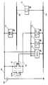
図3に示すように、プラグインハイブリッド車1には、車両の動力を統括制御するハイブリッドビークルECU(以下、「HVECU」と記す。)170、エンジンを制御するエンジンECU171、制動機構を制御するブレーキECU172、盗難防止機能を実現する防盗ECU176等の複数の電子制御装置(以下、「ECU」と記す。)が搭載され、各ECUには単一または複数のCPUが組み込まれている。 As shown in FIG. 3, the plug-in
詳述すると、イグニッションスイッチIGSWがオフ状態であっても低圧の蓄電装置190(例えば、DC12V)から給電可能な第一給電系統180と、イグニッションスイッチIGSWがオン状態の場合に低圧の蓄電装置190から給電可能な第二給電系統181が設けられ、第一給電系統180に防盗ECU176等のボディ監視系のECUが接続され、第二給電系統181にHVECU170、エンジンECU171、ブレーキECU172等のパワートレーン系ECUや、ワイパーやドアミラー等のボディ系ECUが接続されている。 More specifically, from the first
パワートレーン系ECUは、CAN(Controller Area Network)バス185で相互に接続され、ボディ系のECUはLIN(Local Interconnect Network)バス186で相互に接続され、CANバス185とLINバス186とがゲートウェイ191を介して接続され、以って、各ECUに必要な制御情報が送受信可能に構成されている。 The power train ECUs are connected to each other by a CAN (Controller Area Network)
各ECUには、低圧の蓄電装置190から供給されるDC12Vの直流電圧から所定レベルの制御電圧(例えばDC5V)を生成するDCレギュレータが搭載され、DCレギュレータの出力電圧がCPU等の制御回路に供給される。尚、HVECU170には、後述する充電ケーブルを介した蓄電装置150への充電制御を実行するべく、第二給電系統181に加えて第一給電系統180からも給電されている。 Each ECU is equipped with a DC regulator that generates a control voltage (for example, DC5V) of a predetermined level from the DC12V DC voltage supplied from the low-voltage
HVECU170は、イグニッションスイッチIGSWの操作に基づいて、低圧の蓄電装置190から第二給電系統181を介した給電状態を制御する。 The HVECU 170 controls the power supply state from the low-voltage
詳述すると、HVECU170は、イグニッションスイッチIGSWと並列接続された電源リレーRYが開放されている状態でイグニッションスイッチIGSWがオン操作されたことを検出すると、電源リレーRYを閉じて低圧の蓄電装置190から第二給電系統181への給電状態を維持する。 More specifically, when the HVECU 170 detects that the ignition switch IGSW is turned on while the power supply relay RY connected in parallel with the ignition switch IGSW is open, the HVECU 170 closes the power supply relay RY and starts the operation from the low-voltage
この状態で第二給電系統181に接続された各ECUが起動し、夫々所期の制御動作が実行される。 In this state, each ECU connected to the second
さらに、HVECU170は、電源リレーRYが閉じられている状態でイグニッションスイッチIGSWがオフ操作されたことを検出すると、CANバス185を介してイグニッションスイッチIGSWがオフされたことを送信して、第二給電系統181に接続されている各ECUのシャットダウン処理を促す。 Further, when the HVECU 170 detects that the ignition switch IGSW has been turned off while the power supply relay RY is closed, the HVECU 170 transmits that the ignition switch IGSW has been turned off via the
HVECU170は、CANバス185を介して各ECUのシャットダウン処理の終了を認識し、且つ、自身のシャットダウン処理を終えると、電源リレーRYを開放して第二給電系統181への給電状態を停止する。 The HVECU 170 recognizes the end of the shutdown process of each ECU via the CAN
シャットダウン処理とはイグニッションスイッチIGSWのオフに伴って、駆動中の各種のアクチュエータの停止処理や、制御データのメモリへの退避処理等をいい、例えばエンジンECU171であれば、エンジンの停止処理、空燃比等の各種の学習データを含むエンジン制御用のデータの不揮発性メモリへの退避処理をいう。 The shutdown process refers to a process for stopping various actuators being driven, a process for saving control data in a memory, and the like in accordance with the turning off of the ignition switch IGSW. For example, in the case of the engine ECU 171, the engine stop process, air-fuel ratio The process of saving engine control data including various learning data such as the above to a nonvolatile memory.
尚、イグニッションスイッチIGSWは、モーメンタリスイッチまたはオルタネートスイッチの何れの型式のスイッチであってもよく、モーメンタリスイッチを用いる場合には、HVECU170が現在の状態をフラグデータとしてRAMに保持し、そのスイッチの操作エッジでオンされたのかオフされたのかをフラグデータに基づいて判断すればよい。また、従来のキーシリンダにキーを挿入して回転操作するスイッチであってもよい。 The ignition switch IGSW may be either a momentary switch or an alternate switch. When a momentary switch is used, the
HVECU170は、イグニッションスイッチIGSWがオン操作され、電源リレーRYを閉じた後、運転者のアクセル操作等に基づいて車両を走行制御する。 The
HVECU170は、蓄電装置150の充電状態(以下、「SOC(State Of Charge)」と記す。)を監視し、例えばSOCが予め定められた値よりも低くなると、エンジンECU171を介してエンジン100を始動し、動力分割機構130を介して駆動される第1MG110の発電電力を蓄電装置150に蓄える。詳述すると、第1MG110によって発電された電力は、インバータを介して交流から直流に変換され、コンバータを介して電圧が調整された後に蓄電装置150に蓄えられる。このとき、エンジン100で発生した動力の一部は動力分割機構130及び減速機140を介して駆動輪160へ伝達される。
また、HVECU170は、SOCが所定範囲内にあるとき、蓄電装置150に蓄えられた電力または第1MG110により発電された電力の少なくとも一方を用いて第2MG120を駆動し、エンジン100の動力をアシストする。第2MG120の駆動力は減速機140を介して駆動輪160に伝達される。 Further, when the SOC is within a predetermined range,
さらに、HVECU170は、SOCが予め定められた値よりも高くなると、エンジンECU171を介してエンジン100を停止し、蓄電装置150に蓄えられた電力を用いて第2MG120を駆動する。 Further, when the SOC becomes higher than a predetermined value,
一方、車両の制動時等に、HVECU170は、減速機140を介して駆動輪160により駆動される第2MG120を発電機として制御し、第2MG120により発電された電力を蓄電装置150に蓄える。つまり、第2MG120は、制動エネルギーを電力に変換する回生ブレーキとして用いられる。 On the other hand, when braking the vehicle,
つまり、HVECU170は、車両の要求トルクと蓄電装置150のSOC等に基づいて、エンジン100、第1MG110及び第2MG120を制御する。 That is,
図1では、第2MG120による駆動輪160が前輪である場合を示しているが、前輪に代えてまたは前輪とともに後輪を駆動輪160としてもよい。 Although FIG. 1 shows the case where the
高圧の蓄電装置150は充放電可能な直流電源であり、例えば、ニッケル水素やリチウムイオン等の二次電池で構成されている。蓄電装置150の電圧は、例えば200V程度である。蓄電装置150には、第1MG110及び第2MG120によって発電される電力に加えて、車両外部の電源から供給される電力により充電可能に構成されている。 The high-voltage
蓄電装置150として、大容量のキャパシタを採用することも可能であり、第1MG110及び第2MG120による発電電力や車両外部の電源からの電力を一時的に蓄え、その蓄えた電力を第2MG120へ供給可能な電力バッファであればその構成が制限されるものではない。 It is also possible to employ a large-capacity capacitor as
図4に示すように、高圧の蓄電装置150がシステムメインリレー250を介して所定の直流電圧に調整するためのコンバータ200に接続され、コンバータ200の出力電圧が第1インバータ210及び第2インバータ220で交流電圧に変換された後に、第1MG110及び第2MG120に印加されるように構成されている。 As shown in FIG. 4, a high-voltage
コンバータ200は、リアクトルと、電力スイッチング素子である2つのnpn型トランジスタと、2つのダイオードとを含む。リアクトルは、蓄電装置150の正極側に一端が接続され、2つのnpn型トランジスタの接続ノードに他端が接続されている。2つのnpn方トランジスタは直列に接続され、各npn型トランジスタにダイオードが逆並列に接続されている。
npn型トランジスタとして、例えばIGBT(Insulated Gate Bipolar Transistor)を好適に用いることができる。また、npn型トランジスタに代えて、パワーMOSFET(Metal Oxide Semiconductor Field-Effect Transistor)等の電力スイッチング素子を用いることも可能である。 As the npn-type transistor, for example, an IGBT (Insulated Gate Bipolar Transistor) can be suitably used. In place of the npn transistor, a power switching element such as a power MOSFET (Metal Oxide Semiconductor Field-Effect Transistor) can be used.
第1インバータ210は、互いに並列に接続されたU相アーム、V相アーム、及びW相アームを備えている。各相アームは、直列に接続された2つのnpn型トランジスタを含み、各npn型トランジスタにはダイオードが逆並列に接続されている。各相アームを構成する2つのnpn型トランジスタの接続ノードが、第1MG110の対応するコイル端に接続されている。
第1インバータ210は、コンバータ200から供給される直流電力を交流電力に変換して第1MG110へ供給し、或は、第1MG110により発電された交流電力を直流電力に変換してコンバータ200へ供給する。
第2インバータ220も、第1インバータ210と同様に構成され、各相アームを構成する2つのnpn型トランジスタの接続ノードが、第2MG120の対応するコイル端に接続されている。
第2インバータ220は、コンバータ200から供給される直流電力を交流電力に変換して第2MG120へ供給し、或は、第2MG120により発電された交流電力を直流電流に電力してコンバータ200へ供給する。
HVECU170は、イグニッションスイッチIGSWがオン操作されると、システムメインリレー250を閉じ、運転者のアクセル操作等に基づいて、例えば、コンバータ200の電力スイッチング素子を制御して蓄電装置150の出力電圧を所定レベルに昇圧し、第2インバータ220の各相アームを制御して第2MG120を駆動し、例えば、第1インバータ210の各相アームを制御して、第1MG110からの発電電力を直流電力に変換し、コンバータ200で降圧して蓄電装置150を充電する。 When the ignition switch IGSW is turned on, the
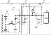
図1及び図4に示すように、プラグインハイブリッド車1には、車両外部の電源から蓄電装置150へ充電電力を供給するための充電ケーブル300を接続するための充電インレット270を備えている。尚、図1では、充電インレット270が車体後部に設けられているが、車体前部に設けられるものであってもよい。 As shown in FIGS. 1 and 4, the plug-in
充電インレット270に接続された充電ケーブル300からの電力が、LCフィルタ280を介して充電回路であるAC/DCコンバータ260により直流電力に変換された後に、高圧の蓄電装置150が充電されるように構成されている。 The power from the charging
充電ケーブル300は、電力ケーブル310の一端側に外部電源、例えば家屋に設けられた電源コンセントと接続するプラグ320が設けられ、他端側に充電インレット270と接続するコネクタ330を備えたアタッチメント340が設けられている。 The charging
図1及び図5に示すように、充電ケーブル300には、当該電力ケーブル310を介して車両に給電可能な定格電流に対応するパルス信号(以下、「コントロールパイロット信号」または「CPLT信号」と記す。)を生成する信号生成部362と、電力ケーブル310を断続するリレー361が組み込まれたCCID(Charging Circuit Interrupt Device)360が設けられ、信号生成部362には、外部電源から供給される電力によって動作するCPU,ROM,RAM及び、コントロールパイロット信号を生成する発振部363とコントロールパイロット信号の信号レベルを検出する電圧検知部364を備えた周辺回路を備えている。 As shown in FIGS. 1 and 5, the charging
また、コネクタ330には、一端が接地されたスイッチ332が抵抗R2と直列接続されるとともに、当該スイッチ332と並列接続された抵抗R3を備えた接続判定回路331が組み込まれ、接続判定回路331の出力がケーブル接続信号PISWとしてHVECU170に入力されるように構成されている。 In addition, the
アタッチメント340には、充電インレット270に挿入されたコネクタ330が離脱しないように機械的なロック機構が設けられ、当該ロック機構を解除するための操作ボタンでなる操作部350が設けられている。 The
充電インレット270から充電ケーブル300のコネクタ330を離脱させる際に、当該操作ボタンを押圧操作することによりロック機構が解除されてコネクタを離脱させることができる。当該操作ボタンが押圧操作されると、それに連動して接続判定回路331のスイッチ332が開成状態に遷移し、押圧操作が解除されると当該スイッチ332が閉成状態に復帰する。 When the
図5に示すように、充電ケーブル300のコネクタ330には、電力ケーブル310と接続された一対の電力端子ピンと、グランド端子ピン、及びコントロールパイロット信号を出力する制御線L1の端子ピンと、接続判定回路331の端子ピンが設けられている。 As shown in FIG. 5, a
充電インレット270には、コネクタ330に設けた各端子ピンと夫々接続する複数の端子ピンと、コントロールパイロット信号が通信される車両側の制御線L2の断線を検出するために、コントロールパイロット信号端子と短絡された断線検出端子ピンが設けられ、さらに、接続判定回路331の端子ピンとグランド間に、接続判定回路331と並列に接続された抵抗R4が設けられている。 Charging
図5に示すように、HVECU170は、上述した第一給電系統180から給電される充電起動制御用のサブCPU1711と、第二給電系統181から給電される充電制御用のメインCPU1710を備えている。各CPUには夫々制御プログラムが格納されたROMが設けられ、メインCPU1710は、ワーキング領域として用いられるRAM及び電源オフ時に制御データを退避する不揮発性メモリを備えている。当該RAMは、サブCPU1711によっても読み書き可能なようにDMAコントローラが設けられている。 As shown in FIG. 5, the
HVECU170には、メインCPU1710の周辺回路として、充電インレット270から出力されるコントロールパイロット信号の信号レベルを検出するとともに、当該信号レベルを二段階に変化させる第一インタフェース回路1712と、コントロールパイロット信号のローレベルを検出する第二インタフェース回路1714と、断線検出端子ピンと接続され、車両側の制御線L2の断線を検出する断線検出回路1713と、接続判定回路331の出力端子と接続された接続状態識別回路1715が設けられている。 The
第一インタフェース回路1712は、ダイオードD1を介して入力されるコントロールパイロット信号の信号レベルを低下させる抵抗R7とスイッチSW1でなる第一降圧回路と、抵抗R8とスイッチSW2でなる第二降圧回路を備えている。 The
第二インタフェース回路1714は、ダイオードD2を介して入力されるコントロールパイロット信号の信号レベルがマイナスレベルになると、メインCPU1710にローレベルの信号を入力し、コントロールパイロット信号の信号レベルがプラスレベルになると、メインCPU1710にハイレベルの信号を入力する抵抗回路(R9,R10,R11)とバッファ回路を備えており、抵抗R9が電源E1(本実施形態ではDC5V)の電源電圧にプルアップされている。 When the signal level of the control pilot signal input via the diode D2 becomes a negative level, the
断線検出回路1713は、断線検出端子ピンを抵抗R12を介して接地するスイッチSW3を備えている。 The
接続状態識別回路1715は、上述した接続判定回路331に並列接続された抵抗R4と、当該並列回路に直列接続され一端が電源E1(本実施形態ではDC5V)に接続された抵抗R5を備えた抵抗分圧回路で構成されている。 The connection
さらに、サブCPU1711の周辺回路として、コントロールパイロット信号の立ち上がりエッジを検出する抵抗R13,R14,R15でなるエッジ検出回路1716が設けられ、当該エッジ検出回路1716の出力がサブCPU1711のウェークアップ用の割込端子WUに接続されている。 Further, as a peripheral circuit of the
イグニッションスイッチIGSWがオフされた後、メインCPU1710がシャットダウン処理を終了して電源リレーRYをオフした状態で、サブCPU1711は低消費電力モードである待機状態に移行している。待機状態とは、CPUがストップ命令またはホールト命令を実行した状態である。 After the ignition switch IGSW is turned off, the
待機状態に移行しているサブCPU1711の割込端子IGに、イグニッションスイッチIGSW信号が入力されると、サブCPU1711は待機状態から通常の動作状態に復帰して、電源リレーRYを閉じてメインCPU1710を立ち上げ、メインCPU1710にイグニッションスイッチIGSWがオンされた通常モードを示す旨の信号を出力する。 When the ignition switch IGSW signal is input to the interrupt terminal IG of the
メインCPU1710は、イグニッションスイッチIGSWがオンされている状態で、上述した車両の要求トルクと蓄電装置150のSOC等に基づいて、エンジン100、第1MG110及び第2MG120を制御する。 The
さらに、メインCPU1710は、接続状態識別回路1715からの入力に基づいて、充電ケーブル300が接続されていないと判断したときに、断線検出回路1713のスイッチSW3をオンして、断線検出端子ピンを抵抗R12を介して接地し、そのときに第一インタフェース回路1712を介して入力されるコントロールパイロット信号のレベルに基づいて、車両側の制御線L2が断線しているか否かを判別するように構成されている。 Further, when the
制御線L2が正常であれば、エッジ検出回路1716のプルダウン抵抗R14により電位がグランドレベルに低下し、制御線L2が断線している場合には、制御電源の電圧にプルアップされた抵抗R9からR10,R11,ダイオードD2,D1,抵抗R13,R14の経路を流れる電流の分圧により電位がグランドレベルより高いレベルに維持される。 If the control line L2 is normal, the potential is lowered to the ground level by the pull-down resistor R14 of the
従って、スイッチSW3をオンした状態で、メインCPU1710に入力されるコントロールパイロット信号のレベルがローレベルであれば正常と判定し、ハイレベルであれば断線していると判定することができる。 Accordingly, it can be determined that the control pilot signal input to the
以下、充電ケーブル300を介して蓄電装置150を充電するHVECU170の充電制御について詳述する。 Hereinafter, the charging control of
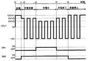
図6に示すように、サブCPU1711が待機状態に移行している場合に、時刻t0で外部電源のコンセントにプラグ320が接続され、充電ケーブル300が充電インレット270に装着されると、信号生成部362から所定レベルの直流電圧V1(例えば、+12V)が出力される。 As shown in FIG. 6, when the
直流電圧V1の立ち上がりエッジ信号がサブCPU1711の割込端子WUに入力されると、サブCPU1711は待機状態から通常の動作状態に復帰して、電源リレーRYを閉じてメインCPU1710を立ち上げ、メインCPU1710に充電モードを示す旨の信号を出力する。 When the rising edge signal of the DC voltage V1 is input to the interrupt terminal WU of the
メインCPU1710は、サブCPU1711から当該充電モードを示す信号を認識し、時刻t1で、第一インタフェース回路1712を介してA/D変換入力端子PCPLTに入力される直流電圧V1を検出すると、第二降圧回路のスイッチSW2をオンして電圧レベルをV1からV2(例えば、+9V)に降圧する。 When the
信号生成部362は、コントロールパイロット信号がV1からV2に低下したことを電圧検知部364により検出すると、時刻t2で、発振部363から所定のデューティサイクルで所定周波数(例えば1KHz)のパルス信号を生成して出力するように制御する。当該パルス信号の信号レベルは±V1であるが、上限レベルは第二降圧回路により降圧されている。 When the
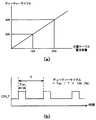
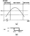
図7(a),(b)に示すように、デューティサイクルは、外部電源から充電ケーブル300を介して車両へ供給可能な電流容量に基づいて設定される値で、充電ケーブル毎に予め設定されている。例えば、電流容量が12Aの場合には20%、電流容量が24Aの場合には40%に設定されている。 As shown in FIGS. 7A and 7B, the duty cycle is a value set based on the current capacity that can be supplied from the external power source to the vehicle via the charging
図6に戻り、メインCPU1710は、第二インタフェース回路1714を介してパルス信号のデューティサイクルを検出して当該充電ケーブル300の電流容量を認識すると、時刻t3で、システムメインリレー250を閉じて(図4参照)、第二降圧回路のスイッチSW2をオンした状態でさらに第一降圧回路のスイッチSW1をオンして、電圧レベルをV2からV3(例えば、+6V)に降圧する。 Returning to FIG. 6, when the
信号生成部362は、コントロールパイロット信号の信号レベルがV2からV3に低下したことを検出すると、リレー361を閉じて車両側に電力ケーブル310から交流電力を供給する。 When the
メインCPU1710は、その後、充電回路としてのAC/DCコンバータ260を制御して(図4参照)、蓄電装置150を充電制御する。 Thereafter,
メインCPU1710は、時刻t4で、蓄電装置150のSOCが所定レベルに達したことを検出すると、AC/DCコンバータ260を停止して充電を終了するとともに、システムメインリレー250を開放して(図4参照)、第一降圧回路のスイッチSW1をオフして、電圧レベルをV3からV2に昇圧する。 When the
信号生成部362は、コントロールパイロット信号がV3からV2に上昇したことを検出すると、リレー361を開放して電力ケーブル310を介した車両側への交流電力の供給を停止する。 When the
メインCPU1710は、時刻t5で、第二降圧回路のスイッチSW2をオフして、コントロールパイロット信号のレベルを当初のV1に戻し、その後信号生成部362からの発振が停止するのを待ってシャットダウン処理に入る。 At time t5, the
サブCPU1711は、メインCPU1710から充電制御が終了した旨の信号を受信すると、電源リレーRYを開放し、その後待機状態に戻る。 When the
上述した充電制御中に、充電インレット270に接続されている充電ケーブル300が引き抜かれると火花放電により端子が劣化する虞があり、適切に充電制御を中断する必要がある。 If the charging
また、充電終了後に充電インレット270に充電ケーブル300が装着された状態でイグニッションスイッチIGSWがオンされると、充電ケーブル300が装着された状態で車両を発進させる虞がある。 Further, when the ignition switch IGSW is turned on with the charging
さらに、充電中にイグニッションスイッチIGSWがオンされ、充電ケーブル300のアタッチメント340に設けられた操作部350が押圧操作されると、充電ケーブル300が引き抜かれたと判断したメインCPU1710によって断線検出回路1713のスイッチSW3がオンされると、CCID360に備えた信号生成部362が誤動作する虞もある。 Further, when the ignition switch IGSW is turned on during charging and the
そこで、本発明では、上述した通り、接続判定回路331の出力端子と接続可能な接続状態識別回路1715を備え、メインCPU1710が、接続状態識別回路1715の出力値に基づいて、スイッチ332が操作部350の操作に基づいてオフ作動したのか、充電ケーブル300が車両から離脱されたのかを識別可能なように構成されている。 Therefore, in the present invention, as described above, the connection
図8(a)に示すように、接続状態識別回路1715は、一端がDC5Vの電源E1に接続された抵抗R5と一端が接地された抵抗R4を直列接続し、抵抗R4,R5の接続ノードを接続判定回路331のケーブル接続信号PISW端子に接続することにより構成され、当該接続ノードが抵抗R6,コンデンサC1を介してメインCPU1710のA/D変換入力端子PPISWに接続されている。尚、抵抗R6は保護用の抵抗であり、コンデンサC1はノイズ吸収のために接続されている。また、A/D変換入力端子のレファレンス電圧はDC5Vに設定されている。 As shown in FIG. 8 (a), the connection
図8(b)に示すように、抵抗R4,R5の接続ノードの電圧レベルは、充電インレット270とHVECU170間の配線が断線しているときに電源E1の電圧と同電位となり、充電インレット270とHVECU170間の配線が短絡しているときに接地電位となる。 As shown in FIG. 8B, the voltage level of the connection node of the resistors R4 and R5 becomes the same potential as the voltage of the power supply E1 when the wiring between the charging
さらに、充電ケーブル300が接続されていない状態、充電ケーブル300が接続され且つ操作部350が押圧されてスイッチ332がオフした状態、充電ケーブル300が接続され且つ操作部350が押圧されずスイッチ332がオンした状態の各状態に対応して、抵抗R4,R5の接続ノードの電圧レベルが電源電位と接地電位の間で個別に識別できるように、抵抗R2、R3,R4,R5の値が設定されている。例えば、図8(a)の図中の()内に示すように、抵抗R2は150Ω、抵抗R3は330Ω、抵抗R4は2.7KΩ、抵抗R5は330Ω±0.5%に設定されている。 Further, the charging
詳述すると、図8(a)に示すように、充電ケーブル300が接続されていない状態では、抵抗R4,R5の分圧レベルが入力される。例えば、図8(a)で例示した抵抗値を適用した場合は、抵抗値が2.7KΩの抵抗R4と抵抗値が330Ω±0.5%の抵抗R5で分圧され、約4.5Vの電圧が入力される。 More specifically, as shown in FIG. 8A, when the charging
充電ケーブル300が接続され且つ操作部350が押圧されてスイッチ332がオフした状態では、抵抗R2,R3,R4の合成抵抗と抵抗R5の分圧レベルが入力される。例えば、図8(a)で例示した抵抗値を適用した場合は、抵抗R2,R3,R4の合成抵抗の抵抗値は約408Ωとなり、抵抗値が330Ω±0.5%の抵抗R5と分圧され、約2.8Vの分圧レベルが入力される。 In a state where the charging
充電ケーブル300が接続され且つ操作部350が押圧されずスイッチ332がオンした状態では、抵抗R2,R4の合成抵抗と抵抗R5の分圧レベルが入力される。例えば、図8(a)で例示した抵抗値を適用した場合は、抵抗R2,RR4の合成抵抗の抵抗値は約142Ωとなり、抵抗値が330Ω±0.5%の抵抗R5と分圧され、約1.5Vの分圧レベルが入力される。 In a state where the charging
従って、コントロールパイロット信号の状態、充電ケーブル300に接続されている外部電源の停電状態、充電ケーブル300のプラグの外部電源への接続状態にかかわらず、メインCPU1710は、接続状態識別回路1715の出力値に基づいて、充電ケーブル300の接続状態、操作部350の操作状態等を正確に判別することができるようになり、各状態に応じて適切に制御を行なうことができるようになる。 Therefore, regardless of the state of the control pilot signal, the power failure state of the external power source connected to the charging
例えば、メインCPU1710は、充電ケーブル300が接続されている状態であれば車両の発進を回避するとともに、断線検出回路1713のスイッチSW3のオン作動を回避し、操作部350が操作された状態であれば充電制御を中断し、断線またはショート状態であれば車両の表示部に故障表示を行なう。 For example, if the charging
充電制御の中断とは、図6に示す時刻t1から時刻t4迄の間に、操作部350が操作されたと判断したメインCPU1710が、システムメインリレー250を開放して(図4参照)、第一降圧回路のスイッチSW1をオフして、電圧レベルをV3からV2に昇圧し、さらに、第二降圧回路のスイッチSW2をオフして、コントロールパイロット信号のレベルを当初のV1に戻す処理をいう。 The interruption of the charge control means that the
充電制御の中断中に、操作部350の操作が解除されたと判断したメインCPU1710は、図6に示す時刻t1からの処理を繰り返すことにより充電制御を再開する。 The
また、例えば、充電制御中にイグニッションスイッチIGSWがオン操作されている場合に、充電ケーブル300が車両から離脱されたと検出したメインCPU1710は、断線検出回路1713のスイッチSW3をオンしてコントロールパイロット信号の制御線L2の断線検出を行なうことができる。 Further, for example, when the ignition switch IGSW is turned on during the charge control, the
さらには、充電ケーブル300が接続されている状態で、コントロールパイロット信号が出力されていなければ、充電ケーブル300のプラグ320がコンセントに接続されていないか、外部電源が停電していると判断し、表示部にその旨の警告表示を行なう警報部を備えることができる。 Furthermore, if the control pilot signal is not output in the state where the charging
即ち、上述したHVECU170により本発明の電子制御装置が構成され、メインCPU1710及びその周辺回路により充電ケーブル300が車両に接続された場合に、信号生成部362の出力端子に接続される制御線L1,L2を介してパルス信号を検出し、パルス信号に基づいて蓄電装置150を充電する制御部であって、接続状態識別回路1715の出力値に基づいて、スイッチ332が操作部350の操作に基づいてオフ作動したのか、充電ケーブル300が車両から離脱されたのかを識別する制御部が構成されている。 That is, when the above-described
以下、別実施形態を説明する。上述の実施形態では、接続状態識別回路1715として、一端がDC5Vの電源E1に接続された抵抗R5と一端が接地された抵抗R4が直列接続され、抵抗R4,R5の接続ノードが接続判定回路331のケーブル接続信号PISW端子に接続された構成を説明したが、接続状態識別回路1715の具体的な構成はこのような回路に限るものではない。 Hereinafter, another embodiment will be described. In the above-described embodiment, as the connection
例えば、図9(a)に示すように、接続状態識別回路1715として、一端が低圧の蓄電装置190から給電される電源E2(DC12V)に接続された抵抗R5と、一端が接地された直並列抵抗回路(抵抗R4,R6,R70で構成される)とを直接接続し、直並列抵抗回路と抵抗R5の接続ノードが接続判定回路331のケーブル接続信号PISW端子に接続され、抵抗R6,R70の接続ノードが抵抗R80,コンデンサC1を介してメインCPU1710のA/D変換入力端子PPISWに接続された構成であってもよい。尚、抵抗R80は保護用の抵抗であり、コンデンサC1はノイズ吸収のために接続されている。 For example, as shown in FIG. 9A, as the connection
この場合にも、充電ケーブル300が接続されていない状態、充電ケーブル300が接続され且つ操作部350が押圧されてスイッチ332がオフした状態、充電ケーブル300が接続され且つ操作部350が押圧されずスイッチ332がオンした状態の各状態に対応して、直並列抵抗回路と抵抗R5の接続ノードの電圧レベルが電源E2の電位と接地電位の間で個別に識別できるように、抵抗R2、R3,R4,R5,R6,R70の値が設定される必要がある。 Also in this case, the charging
さらにこの場合には、DC8V程度からDC14V程度の間で変動する低圧の蓄電装置190の電源電圧に対応して正確に状態を判別するため、図9(b)に示すように、低圧の蓄電装置190の電源電圧の変動に対応して各状態の閾値電圧を設定したマップをメインCPU1710のROMに格納しておく必要がある。 Further, in this case, in order to accurately determine the state corresponding to the power supply voltage of the low-voltage
尚、この場合の接続状態識別回路1715では、A/D変換入力端子PPISWに入力される電圧の最大値が、A/D変換のためのレファレンス電圧以下となるように、抵抗R5,R6,R70によって電源電圧が降圧されている。 In this case, in the connection
メインCPU1710は、低圧の蓄電装置190の電源電圧をモニタして、そのときの電源電圧に対応する閾値電圧をマップから読み出し、接続状態識別回路1715の出力電圧とマップから読み出した閾値電圧を比較することにより、各状態を正確に識別できるようになる。 The
上述の実施形態では、接続状態識別回路1715と接続される接続判定回路331として、スイッチ332に抵抗R3が並列接続された構成を説明したが、抵抗R3に替えて操作部350の操作に連動してスイッチ332を所定時間オフ作動させるタイマ回路を備えてもよい。 In the above-described embodiment, the configuration in which the resistor R3 is connected in parallel to the
例えば、図10に示すように、操作部350の押圧操作に連動してパルスを発生する第二のスイッチ回路333を設けて、上述したスイッチ332として機能するスイッチングトランジスタのコレクタを抵抗R2と接続するとともにエミッタを接地して、第二のスイッチ回路333の立下り信号をトリガとして、例えば数十から数百msec.程度の所定時間パルス信号を出力するタイマ回路としてのワンショットマルチバイブレータ334の出力をスイッチングトランジスタのベースに入力するように構成してもよい。 For example, as shown in FIG. 10, a
この場合、操作部350が押圧操作された初期に、数十から数百msec.程度の所定時間だけスイッチングトランジスタがオフし、その後導通する。 In this case, several tens to several hundreds of msec. The switching transistor is turned off for a predetermined time, and then becomes conductive.
メインCPU1710は、接続状態識別回路1715の出力値に基づいて、充電ケーブル300の操作部350が押圧操作されたと判断して充電制御を中断し、当該所定時間数十から数百msec.経過後に、そのレベルが維持されていると充電ケーブル300が充電インレット270から取り外されたと判断することができる。 Based on the output value of the connection
従って、メインCPU1710は、接続状態識別回路1715の出力値の変動が所定時間継続するか否かに基づいて、スイッチ332が操作部350の操作に基づいてオフ作動したのか、充電ケーブル300が車両から離脱されたのかを識別することができる。 Therefore, the
尚、タイマ回路としてワンショットマルチバイブレータ334を例示したが、操作部350の押圧操作に連動して所定時間スイッチ332をオフ作動させる回路であれば、ワンショットマルチバイブレータ以外のタイマ回路、例えば、CR回路等で構成するものであってもよい。 Although the one-
上述した実施形態では、メインCPU1710は、接続状態識別回路1715の出力値に基づいて充電ケーブル300が車両から離脱されたと検出した後に、断線検出回路1713を介して制御線L2を車両アースに接続する例を説明したが、車速検出装置292で検出される(図4参照)車両の走行速度情報SVをメインCPU1710に入力し、充電ケーブル300が車両から離脱されたと検出した後で、且つ、走行速度が所定速度以上の場合に、断線検出回路1713を介して制御線L2を車両アースに接続するように構成してもよい。 In the embodiment described above, the
走行速度が所定速度以上の場合に、充電ケーブルが車両に接続されている確率は極めて低くなるため、より確実且つ安全に断線検出を行なうことができるようになる。 When the traveling speed is equal to or higher than the predetermined speed, the probability that the charging cable is connected to the vehicle is extremely low, so that the disconnection can be detected more reliably and safely.
この場合、メインCPU1710は、充電ケーブル300が車両から離脱されたと検出した後で、且つ、車両の走行速度が第一の所定速度以上の場合に、断線検出回路1713を介して制御線L2を車両アースに接続し、第一の所定速度より低い第二の所定速度以下の場合に、断線検出回路1713を介して制御線L2を車両アースから切断するように構成してもよい。 In this case, after the
例えば、図11(a),(b)に示すように、第一の所定速度を時速15km、第二の所定速度を時速5kmに設定した場合、車両が発進して時速15km以上の走行速度となったときにスイッチSW3をオン、つまり断線検出回路1713を作動させて制御線L2の断線を検出し、交差点や信号等により時速5km以下の走行速度に減速したときにスイッチSW3をオフ、つまり断線検出回路1713を停止させるのである。 For example, as shown in FIGS. 11 (a) and 11 (b), when the first predetermined speed is set to 15 km / h and the second predetermined speed is set to 5 km / h, the vehicle starts to run at a speed of 15 km / h or more. The switch SW3 is turned on, that is, the
このように、制御線L2の断線検出を行なうための走行速度に閾値を設定することにより、断線検出可能な期間を長く確保することができるようになる。 Thus, by setting a threshold value for the traveling speed for detecting disconnection of the control line L2, it is possible to ensure a long period during which disconnection can be detected.
また、車両の走行速度情報SVに基づいて、断線検出回路1713の作動判断を行なう場合には、スイッチ332と並列接続された抵抗R3や、操作部350の操作に連動してスイッチ332を所定時間オフ作動させるタイマ回路を備えた接続判定回路331に替えて、一端が接地されたスイッチ332と抵抗R2が直列接続された接続判定回路を用いてもよい。 Further, when the operation of the
このような接続判定回路では、操作部350が押圧操作された状態と、コネクタ330が充電インレット270から取り外された状態を識別できないのであるが、操作部350が操作者によって押圧操作された状態で車両が走行するような状態が起こり得ないような走行速度を所定速度として設定することにより、車両が当該所定速度以上となった場合に、コネクタ330が充電インレット270から取り外された状態であると推定することができ、断線検出回路1713を作動させることができるようになる。 In such a connection determination circuit, the state in which the
上述の実施形態では、動力分割機構130によりエンジン100の動力を分割して駆動輪160と第1MG110とに伝達可能なシリーズ/パラレル型のハイブリッド車について説明したが、本発明は、その他の形式のハイブリッド車にも適用可能である。 In the above-described embodiment, the series / parallel type hybrid vehicle in which the power of the
例えば、第1MG110を駆動するためにのみエンジン100を用い、第2MG120でのみ車両の駆動力を発生する、所謂シリーズ型のハイブリッド車や、エンジン100で生成した運動エネルギーのうち回生エネルギーのみが電気エネルギーとして回収されるハイブリッド車や、エンジンを主動力として必要に応じてモータがアシストするモータアシスト型のハイブリッド車等にも、本発明は適用可能である。 For example, a so-called series-type hybrid vehicle that uses the
さらに、エンジン100を備えずに電力で走行するモータのみを備えた電気自動車や、燃料電池を搭載した車両であっても、さらに蓄電装置を備えている燃料電池車にも適用可能である。 Further, the present invention can be applied to an electric vehicle including only a motor that does not include the
上述の実施形態は何れも一具体例であり、各部の具体的な回路構成、制御構成は、本発明の作用効果を奏する範囲で適宜変更設計可能である。 Each of the above-described embodiments is a specific example, and the specific circuit configuration and control configuration of each unit can be appropriately changed and designed within the scope of the effects of the present invention.
1:プラグインハイブリッド車
100:エンジン
110:第1MG(Motor Generator)
120:第2MG(Motor Generator)
130:動力分割機構
140:減速機
150:蓄電装置
160:駆動輪
170:HVECU(電子制御装置)
1710:メインCPU
1711:サブCPU
1712:第一インタフェース回路
1713:断線検出回路
1714:第二インタフェース回路
1715:接続状態識別回路
1716:エッジ検出回路
190:低圧の蓄電装置
200:コンバータ
210:第1インバータ
220:第2インバータ
250:システムメインリレー
260:AC/DCコンバータ
270:充電インレット
280:LCフィルタ
292:車速検出装置
300:充電ケーブル
310:電力ケーブル
320:プラグ
330:コネクタ
331:接続判定回路
332:スイッチ(コネクタ)
350:操作部
360:CCID(Charging Circuit Interrupt Device)
361:リレー(CCID)
362:信号生成部
363:発振部(信号生成部)
364:電圧検知部(信号生成部)
IG:割込端子(イグニッションスイッチ信号)
IGSW:イグニッションスイッチ
L1:制御線(信号生成部の出力端子に接続される)
L2:制御線(車両側)
PISW:ケーブル接続信号
R2:抵抗(操作部に連動してオフ作動するスイッチと直接接続される)
R3:抵抗(接続判定回路のスイッチと並列接続される)
R4、R5:抵抗(抵抗分圧回路を構成する直列接続された抵抗素子)
SV:走行速度情報
SW1:スイッチ(第一降圧回路)
SW2:スイッチ(第二降圧回路)
SW3:スイッチ(断線検出回路)
WU:割込端子(エッジ信号)
1: Plug-in hybrid vehicle 100: Engine 110: First MG (Motor Generator)
120: Second MG (Motor Generator)
130: Power split mechanism 140: Reducer 150: Power storage device 160: Drive wheel 170: HVECU (electronic control unit)
1710: Main CPU
1711: Sub CPU
1712: First interface circuit 1713: Disconnection detection circuit 1714: Second interface circuit 1715: Connection state identification circuit 1716: Edge detection circuit 190: Low-voltage power storage device 200: Converter 210: First inverter 220: Second inverter 250: System Main relay 260: AC / DC converter 270: Charging inlet 280: LC filter 292: Vehicle speed detection device 300: Charging cable 310: Power cable 320: Plug 330: Connector 331: Connection determination circuit 332: Switch (connector)
350: Operation unit 360: CCID (Charging Circuit Interrupt Device)
361: Relay (CCID)
362: Signal generator 363: Oscillator (signal generator)
364: Voltage detection unit (signal generation unit)
IG: Interrupt terminal (ignition switch signal)
IGSW: Ignition switch L1: Control line (connected to the output terminal of the signal generator)
L2: Control line (vehicle side)
PISW: Cable connection signal R2: Resistance (directly connected to a switch that is turned off in conjunction with the operation unit)
R3: Resistance (connected in parallel with the switch of the connection determination circuit)
R4, R5: Resistors (resistance elements connected in series constituting a resistance voltage dividing circuit)
SV: Traveling speed information SW1: Switch (first step-down circuit)
SW2: Switch (second step-down circuit)
SW3: Switch (disconnection detection circuit)
WU: Interrupt terminal (edge signal)
Claims (7)
Translated fromJapanese車両外部の電源と接続するための車両外部電源側コネクタと、車両と接続するための車両側コネクタとを両端に備え、車両外部電源から前記蓄電装置へ電力を給電するケーブルであり、前記車両側コネクタには、一端を接地する信号ラインに、前記車両側コネクタを車両から離脱させるために押圧部が押圧されるとONからOFFになるスイッチ、該スイッチと並列接続する並列抵抗素子、並びに、該並列抵抗素子と直列接続する直列抵抗素子とが設けられており、ユーザにより車両に接続されるケーブルと、
車両に備えられ、前記車両側コネクタと車両を接続させた際に、前記信号ラインを延長する延長信号ラインに、一端を接続して他端を接地する車両の抵抗素子と、
車両に備えられ、前記延長信号ラインからの信号に基づいて制御システムの状態を判定する制御装置と
を備える制御システム。A control system for supplying power from a power source outside the vehicle to a power storage device provided in the vehicle,
And the power supply external to the vehicle-side connector for connecting the power supply external to the vehicle, provided at both ends and the vehicle-side connector for connecting with the vehicle, a cable for feeding power from the power supply external to the vehicle tothe power storage device,the vehicle-sidethe connectors,the signal line to ground oneend, a switch pressing part is turned OFF from oN when it is pressedin order to disengagethe wheel sides connectorfrom the vehicle, a parallel resistive element connected in parallel with the switch, as well as the A series resistance element connected in series with the parallel resistance element, anda cableconnected to the vehicle by the user ;
Provided in the vehicle, when obtained by connectingthe vehicle-side connector and the vehicle, the extended signal line for extendingthe signal lines, a resistance element of the vehicle to ground the other end connected to one end,
A control system provided in a vehicle andcomprising a control device that determines a state of the control system based on a signal from the extension signal line.
車両外部の電源と接続するための第1のコネクタと、車両と接続するための第2のコネクタとを両端に備え、車両外部電源から前記蓄電装置へ電力を給電するケーブルであり、前記第2のコネクタには、一端を接地する第1の信号ラインに、前記第2のコネクタを車両から離脱させるために押圧部が押圧されるとONからOFFになるスイッチ、該スイッチと並列接続する第1の抵抗素子、並びに、該第1の抵抗素子と直列接続する第2の抵抗素子とが設けられており、ユーザにより車両へ接続されるケーブルと、
車両に備えられ、前記第2のコネクタと接続させた際に、前記第1の信号ラインを延長する第2の信号ラインに、一端を接続して他端を接地する第3の抵抗素子を備える第3のコネクタと、
車両に備えられ、前記第3のコネクタにおける第2の信号ラインを延長する第3の信号ラインに、一端を接続して他端を車両内電源に接続する第4の抵抗素子と、前記第3の信号ラインからの信号に基づいて制御システムの状態を判定する制御部を備える制御装置と
を備える制御システム。A control system for supplying power from a power source outside the vehicle to a power storage device provided in the vehicle,
A first connector for connecting the power supply external to the vehicle, with the second ends of the connector for connecting with the vehicle, a cable for feeding power from the power supply external to the vehicle tothe power storage device, the secondthe connector,to the first signal line to one endgrounded, the switch pressing part and the second connectorin order to detach from the vehicle from oN to OFF when it is pressed, the parallel connected to the switch 1 And a second resistance element connected in series with the first resistance element,a cableconnected to the vehicle by the user ,
Provided in the vehicle, when to be connected tothe second connector, to the second signal line extendingthe first signal line, a third resistor element grounding the other end connected to one end A third connector;
Provided in the vehicle, the third signal line extending the second signal lines inthe third connector, a fourth resistor element connected to the other end and one end connected to the vehicle in the power supply,the third And a control device including a control unit that determines a state of the control system based on a signal from the signal line.
前記第3のコネクタは、前記第2のコネクタと接続させた際に、前記第4の信号ラインを延長する第5の信号ライン備え、
前記制御装置は、前記第5の信号ラインを延長する第6の信号ラインを備えるとともに、更に、前記第6の信号ラインから入力される該パルス信号に基づいて、制御システムの状態を判定する制御部を備える請求項2に記載の制御システム。The cable betweenthe second connector andthe first connector provided with a signal generator for generating a pulse signal in accordance with the powered state of the vehicle, further, the signal tothe third connector A fourth signal line for transmitting,
Said third connector, when allowed to connected tothe second connector comprises a fifth signal line extendingthe fourth signal line,
Wherein the control device is provided with a sixth signal line for extendingthe fifth signal line, further, on the basis of the pulse signal inputted fromsaid sixth signal line, the control determines the state of the control system The control system according to claim 2, further comprising a unit.
車両外部の電源と接続するための第1のコネクタと、車両と接続するための第2のコネクタとを両端に備え、車両外部電源から蓄電装置へ電力を給電するケーブルであり、前記第2のコネクタには、一端を接地する第1の信号ラインに、前記第2のコネクタを車両から離脱させるために押圧部が押圧されるとONからOFFになるスイッチ、該スイッチと並列接続する第1の抵抗素子、並びに、該第1の抵抗素子と直列接続する第2の抵抗素子とが設けられており、ユーザにより車両へ接続されるケーブルと、車両に備えられ、前記第2のコネクタと接続させた際に、前記第1の信号ラインを延長する第2の信号ラインに、一端を接続して他端を接地する第3の抵抗素子を備える第3のコネクタと、車両に備えられ、前記第3のコネクタにおける前記第2の信号ラインを延長する第3の信号ラインに、一端を接続して他端を車両内電源に接続する第4の抵抗素子とから構成される制御システムにおける、各抵抗の抵抗電圧を予め記憶する記憶部と、
前記記憶部に記憶する各抵抗素子の抵抗電圧値と前記第3の信号ラインからの入力値に基づいて、前記スイッチ、前記第1の信号ライン、前記第2の信号ライン、又は、前記第3の信号ラインの状態を判定する制御部を備える制御装置。A control device for supplying electric power from a power source outside the vehicle to a power storage device provided in the vehicle,
A first connector for connecting the power supply external to the vehicle, with the second ends of the connector for connecting with the vehicle, a cable for feeding power from the power supply external to the vehicle to power storage device,the secondthe connector,to the first signal line to one endgrounded, the switch pressing part and the second connectorin order to detach from the vehicle from oN to OFF when it is pressed, the first connected in parallel with the switch resistive elements, as well as the first resistive element and a second resistor element connected in seriesare provided, and acable connected to the vehicle by the user, provided in the vehicle, is connected tothe second connector when the, to the second signal line extendingthe first signal line, and a third connector comprising a third resistive element to ground the other end connected to one end, provided in a vehicle,the first 3 connector Thatthe the third signal line extending the second signal lines, in the control system configured to the other end by connecting one end and a fourth resistor element connected to the in-vehicle power supply, the resistor voltage of each resistor A storage unit for storing in advance,
Based on the input values from the resistance voltage value andthe third signal lines of the resistance elements to be stored in the storage unit,said switch,said first signal line,the second signal line, orthe third A control device comprising a control unit for determining the state of the signal line.
前記第3のコネクタは、前記第2のコネクタと接続させた際に、前記第4の信号ラインを延長する第5の信号ラインを備え、
前記制御装置は、前記第5の信号ラインを延長する第6の信号ラインと、前記第6の信号ラインから入力される該パルス信号に基づいて、制御システムの状態を判定する制御部を備える請求項4に記載の制御装置。The cable betweenthe second connector andthe first connector provided with a signal generator for generating a pulse signal in accordance with the powered state of the vehicle, further, the signal tothe third connector A fourth signal line for transmitting,
Said third connector, when allowed to connected tothe second connector comprises a fifth signal line extendingthe fourth signal line,
The said control apparatus is provided with the control part which determines the state of a control system based on the 6th signal line which extends thesaid 5th signal line, and this pulse signal input from thesaid 6th signal line. Item 5. The control device according to Item 4.
車両に備えられ、前記車両側コネクタと車両を接続させた際に、前記信号ラインを延長する延長信号ラインに、一端を接続して他端を接地する車両の抵抗素子と、
を備え、車両外部の電源から車両に備わる蓄電装置へ電力を供給する制御システムに対して、前記ケーブルの接続状態を判定する判定方法であって、
前記延長信号ラインからの信号に基づいて、前記ケーブルが車両から離脱されているのか、前記押圧部が押圧されているのかを判定するケーブル接続状態判定方法。A cable provided with a vehicle external power supply side connector for connecting to a power supply outside the vehicle and a vehicle side connector for connecting to the vehicle at both ends, and supplying power from the vehicle external power supply to the power storage device.isthe signal line for the ground oneend, the switch pressing portion of the vehicle-side connectorto be detached from the vehicle from oN to OFF when it is pressed, the parallel resistance element connected in parallel with the switch, as well, said parallel resistor A series resistor element connected in series with the element, anda cableconnected to the vehicle by the user ;
Provided in the vehicle, when obtained by connectingthe vehicle-side connector and the vehicle, the extended signal line for extendingthe signal lines, a resistance element of the vehicle to ground the other end connected to one end,
The provided, the control system supplies power to the power storage device included from the power supply external to the vehicle to the vehicle, a determination method for determining connection state ofthe cable,
On the basis of the signal from the extension signal line, whetherthe cable is detached from the vehicle, the cable connection state detecting method for determining whetherthe pressing portion is pressed.
Priority Applications (2)
| Application Number | Priority Date | Filing Date | Title |
|---|---|---|---|
| JP2008247793AJP4726939B2 (en) | 2008-09-26 | 2008-09-26 | Control system, control device, and cable connection state determination method |
| US12/563,736US8368350B2 (en) | 2008-09-26 | 2009-09-21 | Control system, control device and cable connection state determining method |
Applications Claiming Priority (1)
| Application Number | Priority Date | Filing Date | Title |
|---|---|---|---|
| JP2008247793AJP4726939B2 (en) | 2008-09-26 | 2008-09-26 | Control system, control device, and cable connection state determination method |
Publications (2)
| Publication Number | Publication Date |
|---|---|
| JP2010081740A JP2010081740A (en) | 2010-04-08 |
| JP4726939B2true JP4726939B2 (en) | 2011-07-20 |
Family
ID=42056701
Family Applications (1)
| Application Number | Title | Priority Date | Filing Date |
|---|---|---|---|
| JP2008247793AActiveJP4726939B2 (en) | 2008-09-26 | 2008-09-26 | Control system, control device, and cable connection state determination method |
Country Status (2)
| Country | Link |
|---|---|
| US (1) | US8368350B2 (en) |
| JP (1) | JP4726939B2 (en) |
Families Citing this family (66)
| Publication number | Priority date | Publication date | Assignee | Title |
|---|---|---|---|---|
| JP4285578B1 (en)* | 2008-01-15 | 2009-06-24 | トヨタ自動車株式会社 | Vehicle charging device |
| US20110145141A1 (en)* | 2009-10-02 | 2011-06-16 | James Blain | Method and apparatus for recharging electric vehicles |
| DE102009045639A1 (en)* | 2009-10-13 | 2011-04-14 | Robert Bosch Gmbh | Electrical connection device for hybrid and electric vehicles and associated method for charging |
| US8698451B2 (en) | 2009-12-18 | 2014-04-15 | General Electric Company | Apparatus and method for rapid charging using shared power electronics |
| US8768533B2 (en)* | 2010-04-09 | 2014-07-01 | Toyota Jidosha Kabushiki Kaisha | Vehicle, communication system, and communication device |
| EP2557746B1 (en) | 2010-04-09 | 2020-05-06 | Toyota Jidosha Kabushiki Kaisha | Communication device, communication system, and vehicle |
| WO2011127446A2 (en) | 2010-04-09 | 2011-10-13 | Aerovironment, Inc. | Portable charging cable with in-line controller |
| JP5258831B2 (en)* | 2010-04-21 | 2013-08-07 | 三菱電機株式会社 | Vehicle charging device |
| US8841881B2 (en)* | 2010-06-02 | 2014-09-23 | Bryan Marc Failing | Energy transfer with vehicles |
| EP2559588B1 (en)* | 2010-06-04 | 2017-11-08 | Honda Motor Co., Ltd. | Control apparatus for vehicle |
| JP5914980B2 (en) | 2010-06-09 | 2016-05-11 | 日産自動車株式会社 | Charge control apparatus and method |
| JP5488220B2 (en) | 2010-06-09 | 2014-05-14 | 日産自動車株式会社 | Charge control apparatus and method |
| USD632645S1 (en) | 2010-06-25 | 2011-02-15 | James Blain | Vehicle recharge station |
| US8305033B2 (en) | 2010-08-05 | 2012-11-06 | Lear Corporation | Proximity detection circuit for on-board vehicle charger |
| IT1401657B1 (en)* | 2010-09-10 | 2013-08-02 | Magneti Marelli Spa | ELECTRICAL SYSTEM OF AN ELECTRIC TRACTION VEHICLE |
| JP5225346B2 (en)* | 2010-09-17 | 2013-07-03 | 中国電力株式会社 | Electric vehicle charging method |
| US20130181516A1 (en)* | 2010-10-05 | 2013-07-18 | Taing Foung Phan | Battery augmentation system and method |
| US20120126747A1 (en)* | 2010-11-19 | 2012-05-24 | Delphi Technologies, Inc. | Battery charger having non-contact electrical switch |
| US9308825B2 (en)* | 2011-01-19 | 2016-04-12 | Aerovironment, Inc. | Electric vehicle docking connector with embedded EVSE controller |
| JP2012162176A (en)* | 2011-02-07 | 2012-08-30 | Toyota Motor Corp | Vehicle and vehicle control method |
| JP5934905B2 (en)* | 2011-03-03 | 2016-06-15 | パナソニックIpマネジメント株式会社 | Charging cable for electric propulsion vehicles |
| US8202124B1 (en) | 2011-03-11 | 2012-06-19 | Lear Corporation | Contact and receptacle assembly for a vehicle charging inlet |
| US8917054B2 (en)* | 2011-08-08 | 2014-12-23 | Lear Corporation | Charger system with safety guardian |
| JP5835152B2 (en)* | 2011-09-16 | 2015-12-24 | 日立金属株式会社 | Vehicle charging device |
| CA2792310C (en) | 2011-10-21 | 2019-06-04 | Keihin Corporation | Electronic control unit |
| JP5852404B2 (en)* | 2011-10-21 | 2016-02-03 | 株式会社ケーヒン | Electronic control unit |
| JP5947518B2 (en)* | 2011-10-21 | 2016-07-06 | 株式会社ケーヒン | Electronic control unit |
| JP5960966B2 (en) | 2011-10-21 | 2016-08-02 | 株式会社ケーヒン | Electronic control unit |
| US9112373B2 (en) | 2012-01-06 | 2015-08-18 | Lear Corporation | Control pilot vehicle interface with non-local return to ground |
| AU2013208273B2 (en) | 2012-01-10 | 2015-11-26 | Hzo, Inc. | Methods, apparatuses and systems for monitoring for exposure of electronic devices to moisture and reacting to exposure of electronic devices to moisture |
| US9146207B2 (en) | 2012-01-10 | 2015-09-29 | Hzo, Inc. | Methods, apparatuses and systems for sensing exposure of electronic devices to moisture |
| CN104054000B (en) | 2012-01-12 | 2016-12-14 | 艾里逊变速箱公司 | The system and method detected for the high voltage cable of hybrid electric vehicle |
| US9762078B2 (en)* | 2012-01-25 | 2017-09-12 | Ford Global Technologies, Llc | Electric vehicle charging system adaptor |
| EP2817645B1 (en) | 2012-02-17 | 2021-04-07 | Allison Transmission, Inc. | High voltage cable detection using rotating machine in hybrid vehicles |
| JP5806144B2 (en)* | 2012-02-27 | 2015-11-10 | トヨタ自動車株式会社 | Vehicle charging device |
| JP5673652B2 (en) | 2012-10-29 | 2015-02-18 | トヨタ自動車株式会社 | Discharge control device for vehicle, discharge connector, vehicle, and discharge control method for vehicle |
| US9563244B2 (en)* | 2013-01-08 | 2017-02-07 | Hzo, Inc. | Apparatuses, systems, and methods for reducing power to ports of electronic devices |
| KR101560114B1 (en) | 2013-01-08 | 2015-10-13 | 에이치제트오 인코포레이티드 | Apparatuses, systems, and methods for detecting and reacting to exposure of an electronic device to moisture |
| US20140267712A1 (en)* | 2013-03-15 | 2014-09-18 | Eaton Corporation | Theft alert system for electric vehicle charging cable |
| EP2808194B1 (en)* | 2013-05-30 | 2016-01-20 | Volvo Car Corporation | Loose plug detection |
| EP2842793B1 (en)* | 2013-09-02 | 2021-03-03 | Volvo Car Corporation | Method for controlling charging of a hybrid or electric vehicle |
| KR101500141B1 (en)* | 2013-09-12 | 2015-03-09 | 현대자동차주식회사 | Method and apparatus for detecting disconnection of 3-phase cable |
| JP5831524B2 (en)* | 2013-10-23 | 2015-12-09 | 株式会社デンソー | Vehicle charging cable |
| KR102171102B1 (en)* | 2014-04-23 | 2020-10-28 | 삼성전자주식회사 | Method and apparatus for detecting condition of safety plug |
| KR20160033511A (en)* | 2014-09-18 | 2016-03-28 | 엘에스산전 주식회사 | Cable installment type charging control apparatus and method thereof |
| KR20160033512A (en)* | 2014-09-18 | 2016-03-28 | 엘에스산전 주식회사 | Cable installment type charging control apparatus and method thereof |
| KR101567239B1 (en)* | 2014-10-02 | 2015-11-13 | 현대자동차주식회사 | Vehicle charger and method for detecting control pilot of electric vehicle supply equipment thereof |
| JP6467971B2 (en)* | 2015-02-18 | 2019-02-13 | 三菱自動車工業株式会社 | Connection detection circuit |
| JP6569122B2 (en)* | 2015-08-05 | 2019-09-04 | 株式会社オートネットワーク技術研究所 | In-vehicle charging system |
| EP3401151B1 (en)* | 2017-05-09 | 2020-12-23 | Volvo Car Corporation | Proximity detection arrangement and method for an electric vehicle |
| JP6542293B2 (en)* | 2017-06-20 | 2019-07-10 | 東芝エレベータ株式会社 | Elevator system |
| KR102554937B1 (en)* | 2018-03-14 | 2023-07-11 | 현대자동차주식회사 | Shut down method for fuel cell vehicles |
| JP6576506B1 (en)* | 2018-05-08 | 2019-09-18 | 三菱電機株式会社 | Vehicle charging device |
| JP6978380B2 (en)* | 2018-06-01 | 2021-12-08 | トヨタ自動車株式会社 | Charge management system |
| CN108767592B (en)* | 2018-08-15 | 2025-04-18 | 汉宇集团股份有限公司 | A charging device |
| US10974610B2 (en)* | 2019-02-18 | 2021-04-13 | Mitsubishi Electric Corporation | Charging device and charging/discharging device |
| JP7265905B2 (en)* | 2019-03-27 | 2023-04-27 | 株式会社Subaru | vehicle |
| US11634041B2 (en)* | 2019-09-19 | 2023-04-25 | Ford Global Technologies, Llc | Access cover detection circuit for electrified vehicle component and corresponding method |
| JP7310576B2 (en)* | 2019-12-06 | 2023-07-19 | トヨタ自動車株式会社 | vehicle controller |
| JP7234960B2 (en)* | 2020-02-07 | 2023-03-08 | トヨタ自動車株式会社 | ELECTRIC VEHICLE AND CONTROL METHOD OF ELECTRIC VEHICLE |
| KR20220098523A (en)* | 2021-01-04 | 2022-07-12 | 엘지이노텍 주식회사 | Electric vehicle charging controller |
| KR102489660B1 (en)* | 2021-02-22 | 2023-01-17 | 주식회사 현대케피코 | System and method for charger diagnosing of electric vehicle |
| DE102021212021A1 (en) | 2021-10-26 | 2023-04-27 | Robert Bosch Gesellschaft mit beschränkter Haftung | Method for charging an electrochemical energy store |
| FR3129736A1 (en)* | 2021-12-01 | 2023-06-02 | Psa Automobiles Sa | Method for monitoring an open circuit fault on a detection circuit |
| TWI849402B (en)* | 2022-04-08 | 2024-07-21 | 飛宏科技股份有限公司 | Detection circuitry for control piot abnormality of a dc charging pile |
| FR3136557B1 (en)* | 2022-06-10 | 2024-06-21 | Delta Dore | DEVICE FOR DETECTING A CUTTING AND/OR AN ANOMALY OF A CONNECTION |
Family Cites Families (10)
| Publication number | Priority date | Publication date | Assignee | Title |
|---|---|---|---|---|
| JPH062944U (en)* | 1992-06-10 | 1994-01-14 | 三菱自動車工業株式会社 | Separate type charger |
| JP3316049B2 (en)* | 1993-06-14 | 2002-08-19 | 住友電装株式会社 | Electric vehicle charging device |
| JP2916348B2 (en)* | 1993-07-22 | 1999-07-05 | 住友電装株式会社 | Electric vehicle charging connector |
| JP3135040B2 (en) | 1995-11-30 | 2001-02-13 | 矢崎総業株式会社 | Electric vehicle charging connector |
| JPH09161882A (en) | 1995-12-06 | 1997-06-20 | Yazaki Corp | Electric vehicle charging connector |
| JPH10178701A (en)* | 1996-12-18 | 1998-06-30 | Honda Motor Co Ltd | Abnormality detection device for charging cable in electric vehicle |
| US6700352B1 (en)* | 1999-11-11 | 2004-03-02 | Radiant Power Corp. | Dual capacitor/battery charger |
| JP4727636B2 (en) | 2007-09-13 | 2011-07-20 | トヨタ自動車株式会社 | VEHICLE CHARGE CONTROL DEVICE AND VEHICLE |
| JP4375472B2 (en) | 2007-10-23 | 2009-12-02 | トヨタ自動車株式会社 | Vehicle charging control device |
| JP4719776B2 (en)* | 2008-07-14 | 2011-07-06 | トヨタ自動車株式会社 | Charging cable, charging control device, and vehicle charging system |
- 2008
- 2008-09-26JPJP2008247793Apatent/JP4726939B2/enactiveActive
- 2009
- 2009-09-21USUS12/563,736patent/US8368350B2/enactiveActive
Also Published As
| Publication number | Publication date |
|---|---|
| JP2010081740A (en) | 2010-04-08 |
| US8368350B2 (en) | 2013-02-05 |
| US20100079105A1 (en) | 2010-04-01 |
Similar Documents
| Publication | Publication Date | Title |
|---|---|---|
| JP4726939B2 (en) | Control system, control device, and cable connection state determination method | |
| JP4969547B2 (en) | Control device and charge control method | |
| JP5185065B2 (en) | Control apparatus and control method | |
| JP5301948B2 (en) | Control device | |
| US8258744B2 (en) | Charging control apparatus for vehicle | |
| JP4719776B2 (en) | Charging cable, charging control device, and vehicle charging system | |
| JP4285578B1 (en) | Vehicle charging device | |
| JP4727636B2 (en) | VEHICLE CHARGE CONTROL DEVICE AND VEHICLE | |
| JP4375472B2 (en) | Vehicle charging control device | |
| JP2011004448A (en) | Charging cable, electronic control device, and charging cable abnormality detection method | |
| JP2011024317A (en) | Control device and control method | |
| WO2010010754A1 (en) | Charge/discharge system and electric vehicle | |
| JP2010123284A (en) | Charging connector and charging cable unit | |
| JP2010148213A (en) | Charging control system, controller, charging control method and control method | |
| JP2012249384A (en) | Vehicle | |
| JP2010081661A (en) | Control device | |
| JP2010104141A (en) | Controller, charge controller, and charge control system | |
| JP2010148159A (en) | Controller and control method |
Legal Events
| Date | Code | Title | Description |
|---|---|---|---|
| A977 | Report on retrieval | Free format text:JAPANESE INTERMEDIATE CODE: A971007 Effective date:20100621 | |
| A131 | Notification of reasons for refusal | Free format text:JAPANESE INTERMEDIATE CODE: A131 Effective date:20100629 | |
| A521 | Request for written amendment filed | Free format text:JAPANESE INTERMEDIATE CODE: A523 Effective date:20100803 | |
| A131 | Notification of reasons for refusal | Free format text:JAPANESE INTERMEDIATE CODE: A131 Effective date:20110201 | |
| A521 | Request for written amendment filed | Free format text:JAPANESE INTERMEDIATE CODE: A523 Effective date:20110228 | |
| TRDD | Decision of grant or rejection written | ||
| A01 | Written decision to grant a patent or to grant a registration (utility model) | Free format text:JAPANESE INTERMEDIATE CODE: A01 Effective date:20110322 | |
| A61 | First payment of annual fees (during grant procedure) | Free format text:JAPANESE INTERMEDIATE CODE: A61 Effective date:20110412 | |
| R150 | Certificate of patent or registration of utility model | Ref document number:4726939 Country of ref document:JP Free format text:JAPANESE INTERMEDIATE CODE: R150 Free format text:JAPANESE INTERMEDIATE CODE: R150 | |
| FPAY | Renewal fee payment (event date is renewal date of database) | Free format text:PAYMENT UNTIL: 20140422 Year of fee payment:3 | |
| R250 | Receipt of annual fees | Free format text:JAPANESE INTERMEDIATE CODE: R250 | |
| R250 | Receipt of annual fees | Free format text:JAPANESE INTERMEDIATE CODE: R250 | |
| R250 | Receipt of annual fees | Free format text:JAPANESE INTERMEDIATE CODE: R250 | |
| R250 | Receipt of annual fees | Free format text:JAPANESE INTERMEDIATE CODE: R250 | |
| R250 | Receipt of annual fees | Free format text:JAPANESE INTERMEDIATE CODE: R250 | |
| R250 | Receipt of annual fees | Free format text:JAPANESE INTERMEDIATE CODE: R250 |