JP4725719B2 - Blade server system and management method thereof - Google Patents
Blade server system and management method thereofDownload PDFInfo
- Publication number
- JP4725719B2 JP4725719B2JP2005091868AJP2005091868AJP4725719B2JP 4725719 B2JP4725719 B2JP 4725719B2JP 2005091868 AJP2005091868 AJP 2005091868AJP 2005091868 AJP2005091868 AJP 2005091868AJP 4725719 B2JP4725719 B2JP 4725719B2
- Authority
- JP
- Japan
- Prior art keywords
- chassis
- management module
- slot
- blade server
- backplane
- Prior art date
- Legal status (The legal status is an assumption and is not a legal conclusion. Google has not performed a legal analysis and makes no representation as to the accuracy of the status listed.)
- Expired - Fee Related
Links
Images

Classifications
- H—ELECTRICITY
- H05—ELECTRIC TECHNIQUES NOT OTHERWISE PROVIDED FOR
- H05K—PRINTED CIRCUITS; CASINGS OR CONSTRUCTIONAL DETAILS OF ELECTRIC APPARATUS; MANUFACTURE OF ASSEMBLAGES OF ELECTRICAL COMPONENTS
- H05K7/00—Constructional details common to different types of electric apparatus
- H05K7/14—Mounting supporting structure in casing or on frame or rack
- H05K7/1438—Back panels or connecting means therefor; Terminals; Coding means to avoid wrong insertion
- H05K7/1459—Circuit configuration, e.g. routing signals
- H—ELECTRICITY
- H05—ELECTRIC TECHNIQUES NOT OTHERWISE PROVIDED FOR
- H05K—PRINTED CIRCUITS; CASINGS OR CONSTRUCTIONAL DETAILS OF ELECTRIC APPARATUS; MANUFACTURE OF ASSEMBLAGES OF ELECTRICAL COMPONENTS
- H05K7/00—Constructional details common to different types of electric apparatus
- H05K7/14—Mounting supporting structure in casing or on frame or rack
- H05K7/1485—Servers; Data center rooms, e.g. 19-inch computer racks
- H05K7/1498—Resource management, Optimisation arrangements, e.g. configuration, identification, tracking, physical location
Landscapes
- Engineering & Computer Science (AREA)
- Microelectronics & Electronic Packaging (AREA)
- Computer Hardware Design (AREA)
- General Engineering & Computer Science (AREA)
- Computer Networks & Wireless Communication (AREA)
- Computer And Data Communications (AREA)
- Multi Processors (AREA)
- Bus Control (AREA)
Description
Translated fromJapanese本発明は、ブレードサーバのシステムマネージメントに関する。 The present invention relates to system management of a blade server.
CPUやハードディスクといったサーバを構成するのに必要な部品を1枚のボード上に搭載してなるブレードを複数枚、シャーシ(ブレード収納ユニット)に収納することで構成されるブレードサーバシステムが知られている。シャーシには、収納された複数のブレードを動作させるのに必要な電源ユニットや冷却ファン、さらにはブレード間のデータ通信を可能にするためのネットワークスイッチなどが搭載されている。ブレードサーバシステムでは、通常、複数のブレードを収納したシャーシが筐体に収容される。 There is known a blade server system configured by housing a plurality of blades each having a part necessary for configuring a server such as a CPU and a hard disk mounted on a single board in a chassis (blade storage unit). Yes. The chassis is equipped with a power supply unit and a cooling fan necessary for operating a plurality of stored blades, and a network switch for enabling data communication between the blades. In a blade server system, a chassis that houses a plurality of blades is usually housed in a housing.
上記のようなブレードサーバシステムにおけるシステムマネージメントとして、SNMP(Simple Network Management Protocol)を利用した手法が知られている(特許文献1参照)。SNMPを利用したシステムマネージメントでは、シャーシ内のブレード間およびシャーシ間におけるネットワークを監視することで、そのネットワークに接続されたデバイス(ブレードや管理モジュール等)の構成を管理している。
しかしながら、従来のSNMPを利用したシステムマネージメントでは、構成情報はそれぞれのデバイスで管理されており、システム全体で一元管理するようにはなっていないため、システム構成の管理が煩雑になる、という問題がある。加えて、障害の発生によりデバイスを交換する場合に、障害が発生したデバイス内に構成情報が存在するため、その構成情報の引き継ぎを簡単に行うことができない、という問題もある。 However, in the conventional system management using SNMP, the configuration information is managed by each device and is not managed by the whole system, so that the management of the system configuration becomes complicated. is there. In addition, when a device is replaced due to the occurrence of a failure, there is also a problem that the configuration information cannot be easily taken over because the configuration information exists in the device in which the failure has occurred.
本発明の目的は、上記問題を解決し、構成情報の管理および設定を容易に行うことのできる、ブレードサーバシステムおよびシステム管理方法を提供することにある。 An object of the present invention is to provide a blade server system and a system management method capable of solving the above problems and easily managing and setting configuration information.
上記の目的を達成するため、本発明は、複数のスロットを有するバックプレーンと、前記複数のスロットに挿入されるブレードサーバおよびシャーシ管理モジュールと、それぞれが前記バックプレーン、ブレードサーバおよびシャーシ管理モジュールを収納する複数のシャーシと、前記複数のシャーシが収納される複数の筐体とを有し、前記バックプレーンは、自身が収納された筐体を識別するための筐体番号、該筐体内のシャーシを識別するための筐体内シャーシ番号、および前記複数のスロットをそれぞれ識別するためのシャーシ内スロットIDが格納された記憶部を備え、前記ブレードサーバは、スロットに挿入されると、該挿入されたスロットに関するシャーシ内スロットIDを前記バックプレーンから取得して保持し、前記シャーシ管理モジュールは、スロットに挿入されると、自身が収納されたシャーシ内の前記ブレードサーバの構成情報として、前記筐体番号および筐体内シャーシ番号を前記バックプレーンから取得して保持するとともに、前記バックプレーンを通じて、前記シャーシ内スロットIDに基づいて前記スロットに挿入されたブレードサーバを管理し、前記複数の筐体の各シャーシに収納された前記シャーシ管理モジュールのうちの1つが、他のシャーシ管理モジュールが保持している前記筐体番号および筐体内シャーシ番号を収集し、該収集した筐体番号および筐体内シャーシ番号に基づいて前記他のシャーシ管理モジュールを管理することを特徴とする。To achieve the above object, the present invention provides a backplane having a plurality of slots, a blade server and a chassis management module inserted into the plurality of slots, andeach of the backplane, the blade server and the chassis management module. a plurality of chassisthat houses, and aplurality of housing the plurality of chassis is accommodated, the backplane housing number for identifying thehousing itself is housed,the housing of the chassis A storage unit storing a chassis number for identifying the chassis and a slot ID for identifying each of the plurality of slots, and the blade server is inserted when inserted into the slot. The slot ID in the chassis related to the slot is acquired from the backplane and retained, and the shear ID is Management module is inserted into the slot,as the configuration information of the blade server in the chassis itself is accommodated holds acquire the housing number and housing chassis number from the backplane, said back A blade server inserted into the slot is managed based on the slot ID in the chassis through a plane, and one of the chassis management moduleshoused in each chassis of the plurality of chassis isanother chassis management module There were collected the housing number and housing chassis number holds, characterized in that it managesthe other chassis management module based on the housing numbers and housing chassis numberand the collected.
上記の構成によれば、各シャーシに設けられたシャーシ管理モジュールのそれぞれが、シャーシ内のブレードサーバの構成を一元管理し、さらに、各シャーシ管理モジュールの1つ(マスタモジュール)が、他のシャーシ管理モジュール(スレーブモジュール)を一元管理する。これにより、バックプレーンのスロットに挿入されたデバイス(ブレードサーバやシャーシ管理モジュール)の構成をシステム全体で一元管理することが可能となる。 According to the above configuration, each chassis management module provided in each chassis centrally manages the configuration of the blade server in the chassis, and one of the chassis management modules (master module) is the other chassis. Centrally manage the management module (slave module). As a result, the configuration of the devices (blade servers and chassis management modules) inserted into the backplane slots can be centrally managed by the entire system.
また、シャーシ管理モジュールおよびブレードサーバは、スロット挿入時にバックプレーンから構成情報(筐体番号、筐体内シャーシ番号、シャーシ内スロットID)を取得するようになっているので、ブレードサーバやシャーシ管理モジュールのデバイスが故障した場合は、故障したデバイスに代えて新たなデバイスをスロットに挿入するだけで、バックプレーンからその挿入したデバイスに自動的に構成情報が提供される。そして、その提供された構成情報に基づいて上記の一元管理が実行される。よって、故障したデバイスの構成情報の引き継ぎを行う必要はない。 In addition, the chassis management module and blade server acquire configuration information (housing number, chassis number in chassis, slot ID in chassis) from the backplane when the slot is inserted. When a device fails, the configuration information is automatically provided from the backplane to the inserted device simply by inserting a new device into the slot instead of the failed device. Based on the provided configuration information, the unified management is executed. Therefore, it is not necessary to take over the configuration information of the failed device.
本発明によれば、バックプレーンのスロットに挿入されたブレードサーバやシャーシ管理モジュールの構成をシステム全体で一元管理することができるので、SNMPを利用した従来の管理方法に比べてシステム管理が容易になる。また、構成情報をバックプレーンから取得することができるので、ブレードサーバやシャーシ管理モジュールの障害時における構成の再設定を容易に行うことができる。このように、本発明は、ブレードサーバのシステム管理の一元化を容易とし、柔軟な構成変更を行うことができる、という効果を奏する。 According to the present invention, the configuration of the blade server and the chassis management module inserted into the slot of the backplane can be centrally managed by the whole system, so that the system management is easier than the conventional management method using SNMP. Become. Further, since the configuration information can be acquired from the backplane, the configuration can be easily reset when a failure occurs in the blade server or the chassis management module. As described above, the present invention has an effect of facilitating the unification of the system management of the blade server and performing a flexible configuration change.
次に、本発明の実施形態について図面を参照して説明する。 Next, embodiments of the present invention will be described with reference to the drawings.
図1は、本発明の一実施形態であるブレードサーバシステムの概略構成を示すブロック図である。図1を参照すると、このブレードサーバシステムは、シャーシ10、11が収容された筐体1と、シャーシ20、21が収容された筐体2とを有する。 FIG. 1 is a block diagram showing a schematic configuration of a blade server system according to an embodiment of the present invention. Referring to FIG. 1, the blade server system includes a casing 1 in which chassis 10 and 11 are accommodated, and a casing 2 in which chassis 20 and 21 are accommodated.
シャーシ10は、複数のスロットを備えた回路基板またはデバイスであるバックプレーン103を有し、このバックプレーン103の各スロットに、複数のCPUブレードサーバ101および2つのCMM(Chassis Management Module)102a、102bがそれぞれ挿入される。また、シャーシ10は、電源ユニットや冷却ファンが搭載されており、スロットに挿入されたCPUブレードサーバ101およびCMM102a、102bに対して、電源やI/Oがバックプレーン103を介して供給されるようになっている。CMM102a、102bの一方がプライマリーで、他方がセカンダリーとして使用される冗長構造になっている。CMM(プライマリー)が故障した場合には、それに代わってCMM(セカンダリー)が動作を引き継ぐことができる。 The chassis 10 has a backplane 103 which is a circuit board or device having a plurality of slots. In each slot of the backplane 103, a plurality of CPU blade servers 101 and two CMMs (Chassis Management Modules) 102a and 102b are provided. Are inserted respectively. The chassis 10 is mounted with a power supply unit and a cooling fan so that power and I / O are supplied via the backplane 103 to the CPU blade server 101 and the
CPUブレードサーバ101のそれぞれには、メモリやCPU、ハードディスクといったサーバを構成するのに必要な部品やネットワーク接続インタフェースの他、BMC(Baseboard Management Controller)101aが設けられている。 Each of the CPU blade servers 101 is provided with a baseboard management controller (BMC) 101a in addition to components necessary for configuring the server, such as a memory, a CPU, and a hard disk, and a network connection interface.
CMM102a、102bも、メモリやCPUなどのコンピュータシステムを構成するのに必要な部品およびネットワーク接続インタフェースを基板上に搭載したものである。CMM102a、102bのそれぞれは、ネットワーク接続インタフェースを介して、スロットに挿入されたCPUブレードサーバ101のそれぞれと接続されるとともに、ネットワーク100aを介して管理用端末30と接続されている。管理用端末30は、メモリ、CPU、ハードディスク、通信装置などを備えるコンピュータシステム、例えばパーソナルコンピュータより構成される。 The
シャーシ11、20、21も、上記シャーシ10と基本的には同じ構成となっている。図1の例では、シャーシ10に収納された各CMMがマスターとされ、他のシャーシ11、20、21に収納された各CMMがスレーブとされている。シャーシ10に収納されたマスターCMMのそれぞれは、他のシャーシ11、20、21に収納されたスレーブCMMのそれぞれとネットワーク100bを介して接続されている。 The chassis 11, 20, and 21 have basically the same configuration as the chassis 10. In the example of FIG. 1, each CMM stored in the chassis 10 is a master, and each CMM stored in the other chassis 11, 20, 21 is a slave. Each of the master CMMs accommodated in the chassis 10 is connected to each of the slave CMMs accommodated in the other chassis 11, 20, and 21 via the
各シャーシ10、11、20、21に設けられたバックプレーン103は、ROMを備えており、このROMに、スロットID、筐体内シャーシ番号、筐体番号、グループ番号などの構成情報が格納されている。スロットIDは、シャーシ内で一意のIDであって、このスロットIDを用いてスロットに挿入されたブレードを識別することができる。筐体内シャーシ番号は、筐体内に収納されたシャーシを識別するための番号である。筐体番号は、筐体を識別するための番号である。グループ番号は、マスターCMMによって管理されるスレーブCMMを識別するための番号である。 The backplane 103 provided in each chassis 10, 11, 20, 21 includes a ROM, and configuration information such as a slot ID, chassis number in the chassis, chassis number, and group number is stored in the ROM. Yes. The slot ID is a unique ID in the chassis, and the blade inserted into the slot can be identified using this slot ID. The chassis number in the housing is a number for identifying the chassis housed in the housing. The case number is a number for identifying the case. The group number is a number for identifying a slave CMM managed by the master CMM.
マスターCMMは、スロットに挿入されると、バックプレーンから筐体内シャーシ番号、筐体番号およびグループ番号を取得して保持する。これと同様に、スレーブCMMも、スロットに挿入されると、バックプレーンから筐体内シャーシ番号、筐体番号およびグループ番号を取得して保持する。 When inserted into the slot, the master CMM acquires the chassis number, chassis number, and group number in the chassis from the backplane and holds them. Similarly, when the slave CMM is inserted into the slot, the chassis number, the chassis number, and the group number in the chassis are acquired from the backplane and held.
また、CPUブレードサーバ101は、スロットに挿入されると、BMC101aが、バックプレーン103からその挿入先のスロットに関するスロットID識別情報を取得して保持する。各CPUブレードサーバ101には、バックプレーン103を通じて電源が供給されるようになっている。各CPUブレードサーバ101における電源制御等のシステムマネージメントは、CPUブレードサーバ101に設けられたBMC101aとCMM102a、102bの間で、バックプレーン103を通じたネットワーク通信を行うことで制御される。 Further, when the CPU blade server 101 is inserted into a slot, the BMC 101a acquires and holds slot ID identification information related to the insertion slot from the backplane 103. Each CPU blade server 101 is supplied with power through the backplane 103. System management such as power control in each CPU blade server 101 is controlled by performing network communication through the backplane 103 between the BMC 101a provided in the CPU blade server 101 and the
次に、本実施形態のブレードサーバシステムの動作について説明する。 Next, the operation of the blade server system of this embodiment will be described.
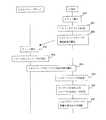
図2に、図1に示したブレードサーバシステムにおいて行われるシステム管理処理の一手順を示す。シャーシ10、11、20、21のそれぞれにおいて、CPUブレードサーバ101およびCMM102a、102bがバックプレーン103のスロットに挿入される。 FIG. 2 shows a procedure of system management processing performed in the blade server system shown in FIG. In each of the chassis 10, 11, 20, and 21, the CPU blade server 101 and the
まず、CMM102a、102bをスロットに挿入すると、バックプレーン103からCMMに電源が供給されてCMM−FW(ファームウェア)が立ち上がり、CMM−FWが、バックプレーン103から筐体番号、筐体内シャーシ番号、グループ番号を取得する(ステップ200)。その後、CMM102a、102bのうちCMM(プライマリー)が、ネットワーク100b上に設けられたDHCP等からネットワーク100b内で一意のID(IPアドレス等)を取得し(ステップ201)、バックプレーン103のスロットに挿入される各CPUブレードサーバの構成監視を開始する(ステップ202)。 First, when the
次に、CPUブレードサーバ101をスロットに挿入すると、バックプレーン103からBMC101aに電源が供給されてBMC−FWが立ち上がり、BMC−FWが、バックプレーンからシャーシ内スロットIDを取得する(ステップ203)。その後、BMC101aとCMM(プライマリー)の間でバックプレーン103を介した通信が行われ、CMM(プライマリー)が、シャーシ内スロットIDに基づいて、シャーシ内の各CPUブレードサーバの構成を管理する(ステップ204)。これにより、一元的にシャーシ内のCPUブレードサーバのシステム管理を行うことが可能となる。 Next, when the CPU blade server 101 is inserted into the slot, power is supplied from the backplane 103 to the BMC 101a, the BMC-FW rises, and the BMC-FW acquires the slot ID in the chassis from the backplane (step 203). Thereafter, communication is performed between the BMC 101a and the CMM (primary) via the backplane 103, and the CMM (primary) manages the configuration of each CPU blade server in the chassis based on the slot ID in the chassis (step). 204). As a result, system management of the CPU blade servers in the chassis can be performed centrally.
上記のようにして、シャーシ10、11、20、21において、CPUブレードサーバ101およびCMMがスロットに挿入された後、各筐体1、2のCMMを筐体内間および筐体間で接続する汎用のネットワーク100b上でマスターおよびスレーブとして動作するマスターCMMおよびスレーブCMMを、所定のアルゴリズム(例えば、IPアドレスが最若番のCMMがマスターとなる等のアルゴリズム)によって決定する(ステップ205)。図1の例では、シャーシ10のCMMがマスターCMMとされている。このアルゴリズムは、管理用端末30からCMMに供給されてもよく、また、CMMに予め格納されていてもよい。 As described above, in the chassis 10, 11, 20, 21, after the CPU blade server 101 and the CMM are inserted into the slots, the general-purpose units that connect the CMMs of the respective cases 1 and 2 between the cases and between the cases. The master CMM and the slave CMM that operate as the master and slave on the
マスターとされたCMMは、各スレーブCMMから筐体番号、筐体内シャーシ番号およびグループ番号を定期的に収集して管理する(ステップ206)。このようにして、マスターCMMは、同じグループ配下のスレーブCMMを筐体番号、筐体内シャーシ番号およびグループ番号に基づいて一元管理する。また、マスターCMMは、管理用端末30との間で、予め定められたTCP/IP等のプロトコルにより通信を行い、管理用端末30からの要求に基づき各シャーシのCPUブレードサーバ101についての状態の表示および制御を行う(ステップ207)。これにより、管理用端末30から各シャーシ10、11、20、21に収納された全てのCPUブレードサーバ101のシステムマネージメントが可能となる。 The master CMM periodically collects and manages the chassis number, chassis number in the chassis, and group number from each slave CMM (step 206). In this way, the master CMM centrally manages slave CMMs under the same group based on the chassis number, the chassis number in the chassis, and the group number. The master CMM communicates with the management terminal 30 using a predetermined protocol such as TCP / IP, and the status of the CPU blade server 101 of each chassis is determined based on a request from the management terminal 30. Display and control are performed (step 207). Thereby, system management of all the CPU blade servers 101 housed in the chassis 10, 11, 20, 21 from the management terminal 30 is possible.
以上説明した本実施形態のブレードサーバシステムによれば、シャーシごとに各CPUブレードサーバがスレーブCMMによって一元管理され、さらに、各スレーブCMMがマスターCMMによって一元管理される。よって、ユーザは、マスターCMMに接続された管理用端末30を用いて、各シャーシに収納したCPUブレードサーバの電源制御、運用状態監視およびログ情報採取を簡単に行うことができる。 According to the blade server system of this embodiment described above, each CPU blade server is centrally managed by the slave CMM for each chassis, and each slave CMM is centrally managed by the master CMM. Therefore, the user can easily perform power supply control, operation status monitoring, and log information collection of the CPU blade server housed in each chassis using the management terminal 30 connected to the master CMM.
また、CPUブレードサーバ101およびCMMの構成情報(スロットID情報、筐体内シャーシ番号、筐体番号、グループ番号など)は、バックプレーン103のROMに格納されており、CPUブレードサーバおよびCMMは、スロット挿入時に、その構成情報を取得するようになっている。よって、ユーザ自身が、CPUブレードサーバおよびCMMの構成情報を設定する必要はない。 Further, the configuration information (slot ID information, chassis number in chassis, chassis number, group number, etc.) of the CPU blade server 101 and CMM is stored in the ROM of the backplane 103. The configuration information is obtained at the time of insertion. Therefore, it is not necessary for the user himself to set the configuration information of the CPU blade server and the CMM.
さらに、CPUブレードサーバまたはCMMに障害が発生して交換が必要になった場合は、新たなCPUブレードサーバまたはCMMをスロットに挿入するだけで、バックプレーン103から構成情報が自動的に提供される。そして、その提供された構成情報に基づいてCMMによる一元管理が実行される。よって、故障したデバイスの構成情報の引き継ぎを行う必要はない。 Furthermore, if a CPU blade server or CMM fails and needs to be replaced, configuration information is automatically provided from the backplane 103 by simply inserting a new CPU blade server or CMM into the slot. . Then, based on the provided configuration information, unified management by CMM is executed. Therefore, it is not necessary to take over the configuration information of the failed device.
また、CMM(プライマリー)が故障した場合は、CMM(セカンダリー)がその故障したCMM(プライマリー)の動作を引き継ぐので、システムの安定性が向上する。 Further, when the CMM (primary) fails, the CMM (secondary) takes over the operation of the failed CMM (primary), so that the stability of the system is improved.
以上説明した本実施形態のブレードサーバシステムは、本発明の一例であり、その構成および動作は適宜変更することができる。例えば、各CCMに、管理用端末30からのアクセスを制限するための認証部を設けてもよい。認証部による認証は、ログインやパスワードの認証を適用する。認証部を設けることで、各グルーブ内にサブグループを形成することが可能になり、サブグループ単位でのシステム管理を実現することが可能となる。加えて、マスターCMMを複数設けることなく、ユーザレベルで、サブグループ単位のCPUブレードサーバの管理を行うことができる。 The blade server system of the present embodiment described above is an example of the present invention, and the configuration and operation thereof can be changed as appropriate. For example, an authentication unit for restricting access from the management terminal 30 may be provided in each CCM. Authentication by the authentication unit applies login and password authentication. By providing the authentication unit, subgroups can be formed in each groove, and system management in units of subgroups can be realized. In addition, it is possible to manage CPU blade servers in units of subgroups at the user level without providing a plurality of master CMMs.
また、マスターCMMとスレーブCMMの間のネットワーク100bと管理用端末30とマスターCMMの間のネットワーク100aを分離してもよい。これにより、環境構築の容易性およびセキュリティが向上する。 Further, the
バックプレーン内のROMを複数設けてもよい(例えば、ROM(プライマリー)とROM(セカンダリー)からなる冗長構造)。この場合は、ROM(プライマリー)が故障した場合に、ROM(セカンダリー)を使用することで、システム信頼性がより高いものとなる。 A plurality of ROMs in the backplane may be provided (for example, a redundant structure including a ROM (primary) and a ROM (secondary)). In this case, when the ROM (primary) breaks down, the system reliability becomes higher by using the ROM (secondary).
また、図1に示した構成では、信頼性を高めるためにCMMを冗長構造としているが、このCMMは1つであってもよい。 Further, in the configuration shown in FIG. 1, the CMM has a redundant structure in order to increase the reliability, but there may be one CMM.
さらに、筐体の数は2つに限られるものではなく、1つ、または、3つ以上であってもよい。 Furthermore, the number of housings is not limited to two, and may be one or three or more.
さらに、筐体に収容されるシャーシの数も2つに限られるものではなく、1つ、または、3つ以上であってもよい。 Furthermore, the number of chassis accommodated in the housing is not limited to two, and may be one or three or more.
さらに、各筐体に収容されるシャーシの数が異なっていてもよい。 Furthermore, the number of chassis accommodated in each housing may be different.
1、2 筐体
10、11、20、21 シャーシ
30 管理用端末
100a、100b ネットワーク
101 CPUブレードサーバ
102a、102b CMM1, 2 Chassis 10, 11, 20, 21 Chassis 30
Claims (7)
Translated fromJapanese前記複数のスロットに挿入されるブレードサーバおよびシャーシ管理モジュールと、
それぞれが前記バックプレーン、ブレードサーバおよびシャーシ管理モジュールを収納する複数のシャーシと、
前記複数のシャーシが収納される複数の筐体とを有し、
前記バックプレーンは、自身が収納された筐体を識別するための筐体番号、該筐体内のシャーシを識別するための筐体内シャーシ番号、および前記複数のスロットをそれぞれ識別するためのシャーシ内スロットIDが格納された記憶部を備え、
前記ブレードサーバは、スロットに挿入されると、該挿入されたスロットに関するシャーシ内スロットIDを前記バックプレーンから取得して保持し、
前記シャーシ管理モジュールは、スロットに挿入されると、自身が収納されたシャーシ内の前記ブレードサーバの構成情報として、前記筐体番号および筐体内シャーシ番号を前記バックプレーンから取得して保持するとともに、前記バックプレーンを通じて、前記シャーシ内スロットIDに基づいて前記スロットに挿入されたブレードサーバを管理し、
前記複数の筐体の各シャーシに収納された前記シャーシ管理モジュールのうちの1つが、他のシャーシ管理モジュールが保持している前記筐体番号および筐体内シャーシ番号を収集し、該収集した筐体番号および筐体内シャーシ番号に基づいて前記他のシャーシ管理モジュールを管理することを特徴とするブレードサーバシステム。A backplane having a plurality of slots;
A blade server and a chassis management module inserted into the plurality of slots;
A plurality ofchassis, each ofwhichcontained the backplane,blade servers and chassis management module,
Aplurality of cases in which the plurality of chassis are housed;
The backplane housing number for identifying thehousing itself is housed,the casing of the housing chassis number for identifying the chassis, and the chassis in a slot for identifying each of said plurality of slots A storage unit storing the ID;
When the blade server is inserted into the slot, the slot ID in the chassis related to the inserted slot is acquired from the backplane and held, and
When the chassis management module is inserted into the slot,the chassis number and the chassis number in the chassis are acquired from the backplaneas the configuration information of the blade server in the chassis in which the chassis management module isstored, and held. Managing the blade server inserted into the slot based on the slot ID in the chassis through the backplane;
One of the chassis management moduleshoused in each chassis of the plurality of housingscollects the housing number and the chassis number in the housing that are held by another chassis management module, and the collected housings blade server system, characterized by managingthe other chassis management module based on the number and housing chassis number.
前記バックプレーンが、自身が収納された筐体を識別するための筐体番号、該筐体内のシャーシを識別するための筐体内シャーシ番号、および前記複数のスロットをそれぞれ識別するためのシャーシ内スロットIDを記憶するステップと、
前記シャーシ管理モジュールが、スロットに挿入されると、自身が収納されたシャーシ内の前記ブレードサーバの構成情報として、前記筐体番号および筐体内シャーシ番号を前記バックプレーンから取得して保持するとともに、前記バックプレーンのスロットに挿入されるブレードサーバの構成の監視を開始するステップと、
前記ブレードサーバが、スロットに挿入されると、該挿入されたスロットに関するシャーシ内スロットIDを前記バックプレーンから取得して保持するステップと、
前記シャーシ管理モジュールが、前記バックプレーンを通じて、前記シャーシ内スロットIDに基づいて前記スロットに挿入されたブレードサーバを管理するステップと、
前記複数の筐体の各シャーシのそれぞれに収納されたシャーシ管理モジュールのうちの1つが、他のシャーシ管理モジュールが保持している前記筐体番号および筐体内シャーシ番号を収集し、該収集した筐体番号および筐体内シャーシ番号に基づいて前記他のシャーシ管理モジュールを管理するステップとを含むシステム管理方法。A plurality of housings, each housing, there the management method performed in a blade server systemhaving at least one of thechassis having a backplane having a plurality of slots blade servers and chassis management module are respectively inserted And
Said backplane, casing number for identifying thehousing itself is housed,the casing of the housing chassis number for identifying the chassis, and the plurality of chassis within the slot to identify each slot Storing an ID;
When the chassis management module is inserted into the slot,as the configuration information of the blade server in the chassis in which the chassis management module isstored, the chassis number and the chassis number in the chassis are acquired from the backplane and held. Starting monitoring the configuration of the blade server inserted into the slot of the backplane;
When the blade server is inserted into a slot, an in-chassis slot ID related to the inserted slot is acquired from the backplane and held;
The chassis management module managing the blade server inserted in the slot based on the slot ID in the chassis through the backplane;
One of the chassis management modules housed ineach chassis of theplurality of chassiscollects the chassis number and the chassis number in the chassis held by the other chassis management module, and the collected chassis system management method comprising the step of managingthe other chassis management module based on body number and enclosure chassis number.
Priority Applications (2)
| Application Number | Priority Date | Filing Date | Title |
|---|---|---|---|
| JP2005091868AJP4725719B2 (en) | 2005-03-28 | 2005-03-28 | Blade server system and management method thereof |
| US11/389,021US7844768B2 (en) | 2005-03-28 | 2006-03-27 | Blade server system and method of managing same |
Applications Claiming Priority (1)
| Application Number | Priority Date | Filing Date | Title |
|---|---|---|---|
| JP2005091868AJP4725719B2 (en) | 2005-03-28 | 2005-03-28 | Blade server system and management method thereof |
Publications (2)
| Publication Number | Publication Date |
|---|---|
| JP2006277033A JP2006277033A (en) | 2006-10-12 |
| JP4725719B2true JP4725719B2 (en) | 2011-07-13 |
Family
ID=37036529
Family Applications (1)
| Application Number | Title | Priority Date | Filing Date |
|---|---|---|---|
| JP2005091868AExpired - Fee RelatedJP4725719B2 (en) | 2005-03-28 | 2005-03-28 | Blade server system and management method thereof |
Country Status (2)
| Country | Link |
|---|---|
| US (1) | US7844768B2 (en) |
| JP (1) | JP4725719B2 (en) |
Families Citing this family (31)
| Publication number | Priority date | Publication date | Assignee | Title |
|---|---|---|---|---|
| US8166539B2 (en)* | 2006-02-24 | 2012-04-24 | Dell Products L.P. | Authentication of baseboard management controller users in a blade server system |
| US8762592B2 (en)* | 2006-08-30 | 2014-06-24 | Dell Products L.P. | System and method for automatic module selection |
| JP2008123464A (en)* | 2006-11-16 | 2008-05-29 | Hitachi Ltd | Server system with remote console mechanism |
| CN101212345A (en)* | 2006-12-31 | 2008-07-02 | 联想(北京)有限公司 | A blade server management system |
| JP2008276320A (en)* | 2007-04-25 | 2008-11-13 | Nec Corp | Virtual system control method and computer system |
| CN100574240C (en)* | 2007-04-30 | 2009-12-23 | 华为技术有限公司 | Access device and principal and subordinate's frame communication means thereof based on industry ethernet |
| US8161391B2 (en)* | 2007-06-12 | 2012-04-17 | Hewlett-Packard Development Company, L.P. | On-board input and management device for a computing system |
| US7689797B2 (en)* | 2007-08-29 | 2010-03-30 | International Business Machines Corporation | Method for automatically configuring additional component to a storage subsystem |
| JP5151393B2 (en)* | 2007-10-25 | 2013-02-27 | 日本電気株式会社 | Blade server system and switch module |
| US9047468B2 (en)* | 2007-12-28 | 2015-06-02 | Intel Corporation | Migration of full-disk encrypted virtualized storage between blade servers |
| US20110093574A1 (en)* | 2008-06-19 | 2011-04-21 | Koehler Loren M | Multi-blade interconnector |
| US8924597B2 (en)* | 2008-06-20 | 2014-12-30 | Hewlett-Packard Development Company, L.P. | Domain management processor |
| EP2304580A4 (en)* | 2008-06-20 | 2011-09-28 | Hewlett Packard Development Co | Low level initializer |
| JP4811489B2 (en)* | 2009-03-27 | 2011-11-09 | 日本電気株式会社 | Server system, collective server device, and MAC address management method |
| TW201142612A (en)* | 2010-05-26 | 2011-12-01 | Hon Hai Prec Ind Co Ltd | System and method for allocating different I2C addresses for blade type systems |
| DE102011118058A1 (en) | 2011-11-09 | 2013-05-16 | Fujitsu Technology Solutions Intellectual Property Gmbh | Server system and method for transmitting at least one chassis-specific configuration value |
| WO2013084336A1 (en)* | 2011-12-08 | 2013-06-13 | 富士通株式会社 | Blade server system and management method for same |
| US8854952B2 (en) | 2011-12-22 | 2014-10-07 | International Business Machines Corporation | Reallocating secondary destinations on a network switch |
| DE102012200042A1 (en)* | 2012-01-03 | 2013-07-04 | Airbus Operations Gmbh | SERVER SYSTEM, AIR OR ROOM VEHICLE AND METHOD |
| US8819779B2 (en)* | 2012-07-05 | 2014-08-26 | Dell Products L.P. | Methods and systems for managing multiple information handling systems with a virtual keyboard-video-mouse interface |
| JP6044228B2 (en)* | 2012-09-27 | 2016-12-14 | 日本電気株式会社 | Storage unit, blade server insertion / removal recording system, and blade server insertion / removal recording method |
| US9367419B2 (en)* | 2013-01-08 | 2016-06-14 | American Megatrends, Inc. | Implementation on baseboard management controller of single out-of-band communication access to multiple managed computer nodes |
| US9858441B2 (en) | 2013-04-03 | 2018-01-02 | Hewlett Packard Enterprise Development Lp | Disabling counterfeit cartridges |
| TWI512603B (en) | 2013-08-23 | 2015-12-11 | Ibm | Electronic appatus and data rolling method therefof |
| DE102014112942B3 (en)* | 2014-09-09 | 2016-01-21 | Fujitsu Technology Solutions Intellectual Property Gmbh | Modular computer system, server module and rack layout |
| DE102014112945B3 (en)* | 2014-09-09 | 2016-01-21 | Fujitsu Technology Solutions Intellectual Property Gmbh | Modular computer system and server module |
| DE102014112943B4 (en) | 2014-09-09 | 2018-03-08 | Fujitsu Ltd. | Modular computer system and server module |
| US9823826B2 (en) | 2014-10-16 | 2017-11-21 | International Business Machines Corporation | User interface module sharing |
| CA3219253A1 (en)* | 2019-01-08 | 2020-07-08 | Bank Of Montreal | Systems and methods for pushing firmware binaries using nested multi-threader operations |
| US11800676B2 (en) | 2020-01-31 | 2023-10-24 | Hewlett Packard Enterprise Development Lp | System and method for secure management of a rack |
| US11321259B2 (en)* | 2020-02-14 | 2022-05-03 | Sony Interactive Entertainment Inc. | Network architecture providing high speed storage access through a PCI express fabric between a compute node and a storage server |
Family Cites Families (24)
| Publication number | Priority date | Publication date | Assignee | Title |
|---|---|---|---|---|
| JPS61273678A (en)* | 1985-05-30 | 1986-12-03 | Toshiba Corp | Collecting system for system information |
| JPS61273679A (en)* | 1985-05-30 | 1986-12-03 | Toshiba Corp | Collecting system for system information |
| JPH07219684A (en) | 1994-02-08 | 1995-08-18 | Hitachi Ltd | Parallel computer system |
| JP3233006B2 (en)* | 1996-03-04 | 2001-11-26 | 三菱電機株式会社 | Configuration control method of information processing device |
| US6192064B1 (en) | 1997-07-01 | 2001-02-20 | Cymer, Inc. | Narrow band laser with fine wavelength control |
| US6820562B2 (en)* | 2000-11-29 | 2004-11-23 | Accelerated Performance, Inc. | Plastic desk with integral computer |
| JP2002312297A (en)* | 2001-04-18 | 2002-10-25 | Nec Corp | Pci host bus bridge system initializing method |
| WO2003014892A2 (en)* | 2001-08-10 | 2003-02-20 | Sun Microsystems, Inc | Server blade |
| US20030078997A1 (en)* | 2001-10-22 | 2003-04-24 | Franzel Kenneth S. | Module and unified network backplane interface for local networks |
| US6968414B2 (en)* | 2001-12-04 | 2005-11-22 | International Business Machines Corporation | Monitoring insertion/removal of server blades in a data processing system |
| JP2003296119A (en) | 2002-04-04 | 2003-10-17 | Matsushita Electric Ind Co Ltd | Software version upgrade method, server device and client device |
| US6925540B2 (en)* | 2002-05-02 | 2005-08-02 | Intel Corporation | Systems and methods for chassis identification |
| JP4055055B2 (en)* | 2002-06-03 | 2008-03-05 | 日本電気株式会社 | Network device and network control method |
| US7583591B2 (en)* | 2002-12-08 | 2009-09-01 | Intel Corporation | Facilitating communications with clustered servers |
| US7191347B2 (en)* | 2002-12-31 | 2007-03-13 | International Business Machines Corporation | Non-disruptive power management indication method, system and apparatus for server |
| US6920049B2 (en)* | 2003-02-05 | 2005-07-19 | Hewlett-Packard Development Company, L.P. | Bladed servers |
| US7444667B2 (en)* | 2003-07-28 | 2008-10-28 | Intel Corporation | Method and apparatus for trusted blade device computing |
| US7499987B2 (en)* | 2003-09-23 | 2009-03-03 | Intel Corporation | Deterministically electing an active node |
| US7483974B2 (en)* | 2003-09-24 | 2009-01-27 | Intel Corporation | Virtual management controller to coordinate processing blade management in a blade server environment |
| US7302593B2 (en)* | 2003-12-18 | 2007-11-27 | Intel Corporation | Method for remotely querying a blade server's physical location within a rack of blade servers |
| US7398401B2 (en)* | 2004-03-25 | 2008-07-08 | Intel Corporation | Method and apparatus for communicating information from an operating system based environment of a server blade to the chassis management module |
| US7512830B2 (en)* | 2004-05-14 | 2009-03-31 | International Business Machines Corporation | Management module failover across multiple blade center chassis |
| US7418608B2 (en)* | 2004-06-17 | 2008-08-26 | Intel Corporation | Method and an apparatus for managing power consumption of a server |
| JP4591149B2 (en)* | 2005-03-29 | 2010-12-01 | 日本電気株式会社 | Cluster system, blade server power control method and program thereof |
- 2005
- 2005-03-28JPJP2005091868Apatent/JP4725719B2/ennot_activeExpired - Fee Related
- 2006
- 2006-03-27USUS11/389,021patent/US7844768B2/ennot_activeExpired - Fee Related
Also Published As
| Publication number | Publication date |
|---|---|
| US7844768B2 (en) | 2010-11-30 |
| US20060218326A1 (en) | 2006-09-28 |
| JP2006277033A (en) | 2006-10-12 |
Similar Documents
| Publication | Publication Date | Title |
|---|---|---|
| JP4725719B2 (en) | Blade server system and management method thereof | |
| US8458329B2 (en) | Data center inventory management using smart racks | |
| US9619243B2 (en) | Synchronous BMC configuration and operation within cluster of BMC | |
| CN101690003B (en) | Determine the method and system of the physical location of equipment | |
| KR100827027B1 (en) | Device diagnostic system | |
| US20070220301A1 (en) | Remote access control management module | |
| US20120331119A1 (en) | Rack server management | |
| US8615571B2 (en) | Network address assignment in a data center | |
| US9619422B2 (en) | Server system and method for transferring at least one chassis-specific configuration value | |
| JP2005228308A (en) | Method and system for recovering failure of flash of blade service processor in server chassis | |
| US20150116913A1 (en) | System for sharing power of rack mount server and operating method thereof | |
| EP2645252A1 (en) | Information processing system and virtual address setting method | |
| US7395323B2 (en) | System and method for providing network address information in a server system | |
| US20100042852A1 (en) | Power-on protection method, module and system | |
| CN113419977B (en) | PCIE equipment management system in server and server | |
| US7818387B1 (en) | Switch | |
| US7499987B2 (en) | Deterministically electing an active node | |
| US8694987B2 (en) | Server rack system | |
| JP2010504680A (en) | Fault tolerant medium access control (MAC) address assignment in network elements | |
| RU2434281C2 (en) | Method, module and system for protection at start-up | |
| CN114124803B (en) | Device management method and device, electronic device and storage medium | |
| CN104253715A (en) | Monitoring system and method of multi-level cascade business | |
| CN108141480B (en) | Method and apparatus for addressing in a system of interconnected cells | |
| TW201201013A (en) | Method and multiple computer system with a failover support to manage shared resources | |
| Cisco | Managing Chassis |
Legal Events
| Date | Code | Title | Description |
|---|---|---|---|
| A621 | Written request for application examination | Free format text:JAPANESE INTERMEDIATE CODE: A621 Effective date:20080213 | |
| A977 | Report on retrieval | Free format text:JAPANESE INTERMEDIATE CODE: A971007 Effective date:20100806 | |
| A131 | Notification of reasons for refusal | Free format text:JAPANESE INTERMEDIATE CODE: A131 Effective date:20100811 | |
| A02 | Decision of refusal | Free format text:JAPANESE INTERMEDIATE CODE: A02 Effective date:20101124 | |
| A521 | Request for written amendment filed | Free format text:JAPANESE INTERMEDIATE CODE: A523 Effective date:20110223 | |
| A911 | Transfer to examiner for re-examination before appeal (zenchi) | Free format text:JAPANESE INTERMEDIATE CODE: A911 Effective date:20110302 | |
| A01 | Written decision to grant a patent or to grant a registration (utility model) | Free format text:JAPANESE INTERMEDIATE CODE: A01 Effective date:20110316 | |
| A61 | First payment of annual fees (during grant procedure) | Free format text:JAPANESE INTERMEDIATE CODE: A61 Effective date:20110329 | |
| R150 | Certificate of patent or registration of utility model | Free format text:JAPANESE INTERMEDIATE CODE: R150 | |
| FPAY | Renewal fee payment (event date is renewal date of database) | Free format text:PAYMENT UNTIL: 20140422 Year of fee payment:3 | |
| LAPS | Cancellation because of no payment of annual fees |