JP4725498B2 - Image processing apparatus, encoding method, and decoding method - Google Patents
Image processing apparatus, encoding method, and decoding methodDownload PDFInfo
- Publication number
- JP4725498B2 JP4725498B2JP2006327876AJP2006327876AJP4725498B2JP 4725498 B2JP4725498 B2JP 4725498B2JP 2006327876 AJP2006327876 AJP 2006327876AJP 2006327876 AJP2006327876 AJP 2006327876AJP 4725498 B2JP4725498 B2JP 4725498B2
- Authority
- JP
- Japan
- Prior art keywords
- pattern
- image
- encoding
- code
- encoded
- Prior art date
- Legal status (The legal status is an assumption and is not a legal conclusion. Google has not performed a legal analysis and makes no representation as to the accuracy of the status listed.)
- Expired - Fee Related
Links
- 238000000034methodMethods0.000titleclaimsdescription31
- 238000009792diffusion processMethods0.000claimsdescription25
- 238000006243chemical reactionMethods0.000claimsdescription9
- 230000000875corresponding effectEffects0.000description45
- 230000002093peripheral effectEffects0.000description6
- 238000010586diagramMethods0.000description5
- 230000001360synchronised effectEffects0.000description5
- 230000006866deteriorationEffects0.000description3
- 230000003252repetitive effectEffects0.000description3
- 239000000284extractSubstances0.000description2
- 239000003550markerSubstances0.000description2
- 238000007781pre-processingMethods0.000description2
- 230000015572biosynthetic processEffects0.000description1
- 230000002596correlated effectEffects0.000description1
- 238000001514detection methodMethods0.000description1
- 238000005516engineering processMethods0.000description1
- 230000006870functionEffects0.000description1
- 239000000203mixtureSubstances0.000description1
- 238000010187selection methodMethods0.000description1
- 238000003786synthesis reactionMethods0.000description1
- 230000002194synthesizing effectEffects0.000description1
Images


Landscapes
- Facsimile Image Signal Circuits (AREA)
- Image Processing (AREA)
- Editing Of Facsimile Originals (AREA)
Description
Translated fromJapanese本発明は、画像に付加情報を付加するため画像の符号化を行う又は画像に付加された付加情報の復号化を行う画像処理装置、その符号化方法及び復号化方法に関する。 The present invention relates to an image processing apparatus that performs encoding of an image to add additional information to an image or decodes additional information added to an image, and an encoding method and decoding method thereof.
多値画像を2値化して出力するに際して行われる誤差拡散処理では、誤差拡散に特有の固定パターンが生じることがある。例えば、読取時の解像度が600dpi、印刷時の解像度が1200dpiのコピー機の場合、印刷時に600dpiの多値画像を1200dpiの2値画像に変換することとなる。つまり、読み取られた多値画像の1画素分を、2×2画素分の2値画像に変換することとなるが、中間調部分の濃度パターンは複数種類考えられる(例えば白1画素、黒3画素の場合、2×2画素における白1画素の位置によって4種類の濃度パターンがある)。そのため、コピー機において任意の1種類の濃度パターンを選択することとなる。この選択方法が固定化することにより誤差拡散処理後の2値画像の濃度特性が固定パターンとなるのである。従来は、固定化を避けるため、乱数により任意の濃度パターンを選択する等の対策がとられていた(例えば、特許文献1参照)。 In error diffusion processing performed when a multi-value image is binarized and output, a fixed pattern peculiar to error diffusion may occur. For example, in the case of a copier having a resolution of 600 dpi for reading and a resolution of 1200 dpi for printing, a multi-valued image of 600 dpi is converted to a binary image of 1200 dpi for printing. That is, one pixel of the read multi-valued image is converted into a binary image of 2 × 2 pixels, but a plurality of halftone density patterns are conceivable (for example, white 1 pixel, black 3 In the case of pixels, there are four types of density patterns depending on the position of one white pixel in 2 × 2 pixels). Therefore, an arbitrary one type of density pattern is selected in the copier. When this selection method is fixed, the density characteristics of the binary image after the error diffusion process become a fixed pattern. Conventionally, in order to avoid immobilization, measures such as selecting an arbitrary density pattern with random numbers have been taken (see, for example, Patent Document 1).
一方、画像に付加情報を付加することもよく行われており、この付加方法については、様々な方法が考えられている。
例えば、符号化によって付加情報を画像に埋め込む方法(例えば、特許文献2参照)、地紋の模様に付加情報を埋め込む方法(例えば、特許文献3参照)がある。特許文献2に記載の方法では、付加情報を埋め込んだ画像データの印刷物からは付加情報を復号でき、その複写物からは付加情報の復号ができないように、画像データの画像形成条件等を調節している。また、特許文献3に記載の方法では、解像度、パターンの異なる複数種類の地紋パターンを組み合わせることにより、複写物では付加情報が再現されないように地紋画像を構成している。
For example, there are a method of embedding additional information in an image by encoding (for example, see Patent Document 2) and a method of embedding additional information in a background pattern (for example, see Patent Document 3). In the method described in
しかしながら、上述した方法では印刷物において符号化が行われている起点がわからないため、復号化の際にはこの起点を検出しなければ復号化できない。従って、当該起点を示すため付加情報を付加する画像にマーキングをしなければならなかった。
また、より正確に復号することができる新しい手法も望まれる。However, in the above-described method, the starting point where the encoding is performed on the printed matter is not known, and therefore decoding cannot be performed unless this starting point is detected at the time of decoding. Therefore, it has been necessary to mark an image to which additional information is added in order to indicate the starting point.
Also, a new technique that can decode more accurately is desired.
本発明の課題は、付加情報の復号にあたり、容易かつ正確な復号を可能とすることである。 An object of the present invention is to enable easy and accurate decoding when decoding additional information.
請求項1に記載の発明は、画像処理装置において、
M系列符号を2次元に配置した符号化パターンを、識別コードごとに記憶する記憶手段と、
符号化対象の対象画像に付加する付加情報を識別コードに変換するコード変換手段と、
前記変換された識別コードに対応する符号化パターンを前記記憶手段から取得して前記対象画像にあてはめ、あてはめた画像部分の全部又は一部を、対応する符号化パターンのM系列符号に応じて符号化する符号化手段と、
を備えることを特徴とする。The invention according to
Storage means for storing, for each identification code, an encoding pattern in which M-sequence codes are arranged two-dimensionally;
Code conversion means for converting additional information added to the target image to be encoded into an identification code;
An encoding pattern corresponding to the converted identification code is acquired from the storage means and applied to the target image, and all or part of the applied image portion is encoded according to the M-sequence code of the corresponding encoding pattern. Encoding means for
It is characterized by providing.
請求項2に記載の発明は、請求項1に記載の画像処理装置において、
前記対象画像は多値画像であり、
前記符号化手段は、前記符号化パターンをあてはめた画像部分のうち、中間調の画像部分の濃度パターンを、その中間調の画像部分に対応するM系列符号に応じた濃度パターンに置き換えることにより、符号化を行うことを特徴とする。The invention according to
The target image is a multi-valued image;
The encoding means replaces the density pattern of the halftone image portion of the image portion to which the encoding pattern is applied with a density pattern corresponding to the M-sequence code corresponding to the halftone image portion, It is characterized by encoding.
請求項3に記載の発明は、請求項1に記載の画像処理装置において、
前記対象画像は文字画像を含み、
前記符号化手段は、前記符号化パターンをあてはめた画像部分のうち、文字画像の輪郭部分の濃度パターンを、その輪郭部分に対応するM系列符号に応じた濃度パターンに置き換えることにより、符号化を行うことを特徴とする。The invention according to
The target image includes a character image,
The encoding means performs encoding by replacing the density pattern of the contour portion of the character image in the image portion to which the encoding pattern is applied with a density pattern corresponding to the M-sequence code corresponding to the contour portion. It is characterized by performing.
請求項4に記載の発明は、請求項1〜3の何れか一項に記載の画像処理装置において、
前記符号化手段は、誤差拡散処理が施された対象画像について前記符号化を行うことを特徴とする。The invention according to
The encoding means performs the encoding on a target image that has been subjected to error diffusion processing.
請求項5に記載の発明は、請求項1に記載の画像処理装置において、
前記対象画像は地紋パターンの繰り返しからなる地紋画像であり、
前記符号化手段は、前記符号化パターンをあてはめた画像部分の全部又は一部の地紋パターンを、その全部又は一部に対応するM系列符号に応じた地紋パターンに置き換えることにより、符号化を行うことを特徴とする。The invention according to
The target image is a copy-forgery-inhibited pattern image formed by repeating a copy-forgery-inhibited pattern.
The encoding means performs encoding by replacing all or part of the tint block pattern of the image portion to which the coding pattern is applied with a tint block pattern corresponding to the M sequence code corresponding to all or part of the pattern pattern. It is characterized by that.
請求項6に記載の発明は、画像処理装置において、
M系列符号を2次元に配置した符号化パターンを、識別コードごとに記憶する記憶手段と、
請求項1〜5の何れか一項に記載の画像処理装置によって符号化された符号化画像に対し、前記記憶された符号化パターンを走査させ、当該符号化パターンのM系列符号と一致する画像部分を検出し、一致する符号化パターンに対応する識別コードに変換する復号化手段と、
前記変換された識別コードを前記符号化画像に付加された付加情報に変換し、当該付加情報を出力するコード変換手段と、
を備えることを特徴とする。According to a sixth aspect of the present invention, in the image processing apparatus,
Storage means for storing, for each identification code, an encoding pattern in which M-sequence codes are arranged two-dimensionally;
An image that matches the M-sequence code of the encoded pattern by scanning the stored encoded pattern with respect to the encoded image encoded by the image processing device according to any one of
Code conversion means for converting the converted identification code into additional information added to the encoded image and outputting the additional information;
It is characterized by providing.
請求項7に記載の発明は、符号化方法において、
符号化対象の対象画像に付加する付加情報を識別コードに変換するコード変換工程と、
M系列符号を2次元に配置した符号化パターンが識別コードごとに記憶された記憶手段から、前記変換された識別コードに対応する符号化パターンを取得して前記対象画像にあてはめ、あてはめた画像部分の全部又は一部を、対応する符号化パターンのM系列符号に応じて符号化する符号化工程と、
を含むことを特徴とする。The invention according to
A code conversion step for converting additional information to be added to the target image to be encoded into an identification code;
An image portion obtained by obtaining an encoding pattern corresponding to the converted identification code from a storage means in which an encoding pattern in which an M-sequence code is arranged in two dimensions is stored for each identification code, and applying the acquired encoding pattern to the target image. An encoding step of encoding all or a part of the signal in accordance with the M-sequence code of the corresponding encoding pattern;
It is characterized by including.
請求項8に記載の発明は、請求項7に記載の符号化方法において、
前記対象画像は多値画像であり、
前記符号化工程では、前記符号化パターンをあてはめた画像部分のうち、中間調の画像部分の濃度パターンを、その中間調の画像部分に対応するM系列符号に応じた濃度パターンに置き換えることにより、符号化を行うことを特徴とする。The invention according to claim 8 is the encoding method according to
The target image is a multi-valued image;
In the encoding step, among the image portions to which the encoding pattern is applied, by replacing the density pattern of the halftone image portion with a density pattern corresponding to the M series code corresponding to the halftone image portion, It is characterized by encoding.
請求項9に記載の発明は、請求項7に記載の符号化方法において、
前記対象画像は文字画像を含み、
前記符号化工程では、前記符号化パターンをあてはめた画像部分のうち、文字画像の輪郭部分の濃度パターンを、その輪郭部分に対応するM系列符号に応じた濃度パターンに置き換えることにより、符号化を行うことを特徴とする。The invention according to claim 9 is the encoding method according to
The target image includes a character image,
In the encoding step, encoding is performed by replacing the density pattern of the outline part of the character image in the image part to which the encoding pattern is applied with a density pattern corresponding to the M-sequence code corresponding to the outline part. It is characterized by performing.
請求項10に記載の発明は、請求項7〜9の何れか一項に記載の符号化方法において、
前記符号化工程では、誤差拡散処理が施された対象画像について前記符号化を行うことを特徴とする。Invention of
In the encoding step, the encoding is performed on a target image on which error diffusion processing has been performed.
請求項11に記載の発明は、請求項7に記載の符号化方法において、
前記対象画像は地紋パターンの繰り返しからなる地紋画像であり、
前記符号化工程では、前記符号化パターンをあてはめた画像部分の全部又は一部の地紋パターンを、その全部又は一部に対応するM系列符号に応じた地紋パターンに置き換えることにより、符号化を行うことを特徴とする。The invention according to
The target image is a copy-forgery-inhibited pattern image formed by repeating a copy-forgery-inhibited pattern.
In the encoding step, encoding is performed by replacing all or part of the tint block pattern of the image portion to which the coding pattern is applied with a tint block pattern corresponding to the M sequence code corresponding to all or part of the pattern pattern. It is characterized by that.
請求項12に記載の発明は、復号化方法において、
請求項7〜12の何れか一項に記載の符号化方法によって符号化された符号化画像に対し、M系列符号を2次元に配置した符号化パターンであって、識別コードごとに作成された符号化パターンを走査させ、当該符号化パターンのM系列符号と一致する画像部分を検出し、一致する符号化パターンに対応する識別コードに変換する復号化工程と、
前記変換された識別コードを前記符号化画像に付加された付加情報に変換し、当該付加情報を出力するコード変換工程と、
を含むことを特徴とする。The invention according to
An encoded pattern in which an M-sequence code is two-dimensionally arranged for an encoded image encoded by the encoding method according to any one of
A code conversion step of converting the converted identification code into additional information added to the encoded image and outputting the additional information;
It is characterized by including.
請求項1〜3、5、7〜11に記載の発明によれば、自己相関性が高い符号化パターンを用いて対象画像の符号化を行うので、その符号化画像において符号化パターンと一致性の高い画像部分を検出して復号すればよく、容易に復号することができる。また、M系列符号の符号長をLとすると、符号化画像からL個程度の符号が検出できれば復号用の符号化パターンと同期をとることができるため、対象画像の一部のみの符号化でも精度良く正確に復号することができる。また、符号化画像にノイズや画質劣化が生じた場合でも復号化が可能となる。さらに、同期をとることにより、符号化画像において符号化の起点が分からない場合でも復号化することができる。従って、容易かつ正確な復号を行うことが可能である。 According to the first to third aspects of the present invention, since the target image is encoded using an encoding pattern having high autocorrelation, the encoded image matches the encoding pattern. It is only necessary to detect and decode an image portion having a high height, and the image portion can be easily decoded. Also, if the code length of the M-sequence code is L, it is possible to synchronize with the coding pattern for decoding if about L codes can be detected from the coded image. Decoding can be performed accurately and accurately. Also, decoding can be performed even when noise or image quality deterioration occurs in the encoded image. Furthermore, by synchronizing, even if the starting point of encoding is not known in the encoded image, it can be decoded. Therefore, easy and accurate decoding can be performed.
請求項4に記載の発明によれば、符号化によって濃度パターンを置き換えることにより、誤差拡散処理によってパターンが固定化するのを防止することができる。 According to the fourth aspect of the invention, by replacing the density pattern by encoding, it is possible to prevent the pattern from being fixed by error diffusion processing.
請求項6、12に記載の発明によれば、符号化に用いられたものと同一の符号化パターンを用いて、符号化画像において符号化パターンが当てはめられた画像部分を検出し、これを復号することができる。すなわち、自己相関性の高い符号化パターンを復号用として用いることにより、符号化時に画像にあてはめられた符号化パターンと同期をとることができ、復号化の起点が分からない場合でも復号を行うことができる。また、M系列符号の符号長をLとすると、符号化画像からL個程度の符号が検出できれば復号用の符号化パターンと同期をとることができるため、対象画像の一部のみの符号化でも精度良く正確に復号することができる。従って、容易かつ正確な復号を行うことが可能である。 According to the sixth and twelfth aspects of the present invention, by using the same encoding pattern as that used for encoding, an image portion to which the encoding pattern is applied is detected in the encoded image, and this is decoded. can do. In other words, by using an encoding pattern with high autocorrelation for decoding, it is possible to synchronize with the encoding pattern applied to the image at the time of encoding, and to perform decoding even when the starting point of decoding is not known Can do. Also, if the code length of the M-sequence code is L, it is possible to synchronize with the coding pattern for decoding if about L codes can be detected from the coded image. Decoding can be performed accurately and accurately. Therefore, easy and accurate decoding can be performed.
〈第1実施形態〉
第1実施形態では、誤差拡散処理後にM系列符号を用いて画像の符号化を行うことにより、当該画像に付加情報を付加する例を説明する。<First Embodiment>
In the first embodiment, an example in which additional information is added to an image by encoding the image using an M-sequence code after error diffusion processing will be described.
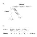
図1に、本実施形態における画像処理装置10の構成を示す。
画像処理装置10は、入力画像に対して誤差拡散処理を施した後、当該処理画像の一部を符号化して付加情報を付加した符号化画像を出力するものである。画像処理装置10は、誤差拡散処理によって多値の入力画像を、2値の出力画像に変換する。
画像処理装置10は、図1に示すように、誤差拡散処理を行うための加算部11、閾値判定部12、濃度演算部13、減算部14、拡散部15、誤差メモリ16、パターン生成部17、パターンメモリ18、符号化を行うための符号化部20、パターンメモリ21を備えて構成されている。FIG. 1 shows a configuration of an
The
As shown in FIG. 1, the
入力画像は多値画像である。例えば、8ビットの入力画像であれば、0〜255の画素値をとりうる。入力画像は画素ごとに画像処理装置10に入力される。
加算部11は、入力された処理対象の画素(これを注目画素という)より以前に入力された画素について生じた誤差値Eと、注目画素の画素値Cとを加算し、閾値判定部12、減算部14に出力する。The input image is a multivalued image. For example, in the case of an 8-bit input image, pixel values from 0 to 255 can be taken. The input image is input to the
The
閾値判定部12は、複数の閾値THi(iは階調を示す)を有し、加算部11からの入力値E+Cとこの閾値THiとを比較して、どの階調に対応するかを判定する。
本実施形態では、2値の出力画像を5階調で出力する場合を例に説明する。閾値判定部12は4つの閾値TH0、TH1、TH2、TH3を持ち、この閾値TH0〜TH3を用いて以下のように階調F(F=0〜4)を判定する。
0≦E+C<TH0のとき、F=0
TH0≦E+C<TH1のとき、F=1
TH1≦E+C<TH2のとき、F=2
TH2≦E+C<TH3のとき、F=3
TH3≦E+C≦255のとき、F=4
判定結果である階調Fの情報は、濃度演算部13、パターン生成部17に出力される。The
In the present embodiment, a case where a binary output image is output in five gradations will be described as an example. The
When 0 ≦ E + C <TH0, F = 0
When TH0 ≦ E + C <TH1, F = 1
When TH1 ≦ E + C <TH2, F = 2
When TH2 ≦ E + C <TH3, F = 3
When TH3 ≦ E + C ≦ 255, F = 4
The information of the gradation F that is the determination result is output to the
濃度演算部13は、閾値判定部12から入力される階調Fの情報に基づいて、階調Fに応じた濃度値を演算する。すなわち、出力画像においてとり得る濃度値の範囲が0〜255であり、この濃度範囲を2×2画素の濃度パターンで表現する場合、1画素分の濃度は256/4=64である。よって、階調F=0のとき濃度値D=0、F=1のときD=64、F=2のときD=128、F=3のときD=192、F=4のときD=255である。演算された濃度値Dは減算部14に出力される。 The
減算部14は、加算部11から入力された加算値E+Cと、濃度演算部13から入力された濃度値Dとの減算を行い、その差である誤差値Eを演算して拡散部15に出力する。 The subtracting
拡散部15は、注目画素の周辺画素に誤差値Eを拡散するため、各周辺画素に応じた重み付け係数を誤差値Eに乗算する。拡散部15は、重み付け係数を乗算した誤差値Eを各周辺画素に配分する誤差値として誤差メモリ16に出力する。 The
誤差メモリ16は、拡散部15から入力された誤差値Eを配分先の周辺画素毎に記憶する。誤差メモリ16は、配分先の周辺画素が注目画素として加算部11に入力されるタイミングで、当該周辺画素に対応する誤差値Eを加算部11に出力する。 The
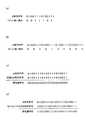
パターン生成部17は、閾値判定部12から入力される階調Fの情報に基づき、階調Fつまり5値の1画素に対応する、2値の2×2画素の濃度パターンを出力する。すなわち、2倍の解像度変換を行い、変換後の2×2画素において白画素と黒画素の割合、位置を異なるものとすることにより、2値の濃度パターンで5階調を表現するものである。
2×2画素の2値の濃度パターンで5階調を表現する場合、図2に示すような濃度パターンが考えられる。階調0と階調4では濃度パターンは1種類のみだが、階調1〜3の中間調については白画素、黒画素の位置によって複数種類の濃度パターンが存在する。
パターンメモリ18には、各階調0〜4に応じたこれら濃度パターンが予め格納されており、パターン生成部17は、このパターンメモリ18に記憶されている濃度パターンのうち、階調Fに対応する濃度パターンを選択する。一つの階調Fに複数の濃度パターンが存在する場合にはそのうち任意の一つを選択する。このとき、ランダムに選択することとしてもよいし、周期的に選択してもよい。選択した濃度パターンは符号化部20に出力される。The
When expressing 5 gradations with a binary density pattern of 2 × 2 pixels, a density pattern as shown in FIG. 2 can be considered. In
The
符号化部20は、パターン生成部17から入力される濃度パターンからなる画像を符号化し、付加情報を付加する。
符号化部20は、符号化においてM系列符号を2次元に配列した符号化パターンを用いる。The
The
M系列符号について説明する。
M系列符号は、n個のフリップフロップと、排他論理和を含めたフィードバックループとから得られる疑似乱数数列のうち、その周期が最長となる系列をいう。その長さLは、L=2n−1で表される。The M sequence code will be described.
The M-sequence code is a sequence having the longest cycle among pseudo-random number sequences obtained from n flip-flops and a feedback loop including exclusive OR. The length L is represented by L = 2n −1.
M系列符号の特徴は、符号のランダム性と均等性、自己相関の高さにある。
これら特徴について、L=23−1=7の周期によるM系列符号「0100111」の例で説明する。この配列から分かるようにM系列符号は〈0〉と〈1〉の符号が含まれる割合がほぼ同じであり、複数のM系列符号を連続的に並べると、ランダムな符号〈0〉、〈1〉の配列となる。しかし、ランダム性を有しながらもその配列は一定のパターンを構成しており、均等性をも併せ持っている。The characteristics of the M-sequence code are the randomness and uniformity of the code and the high autocorrelation.
These features will be described using an example of an M-sequence code “0100111” with a period of L = 23 −1 = 7. As can be seen from this arrangement, the ratio of the M-sequence code including the codes <0> and <1> is almost the same. When a plurality of M-sequence codes are arranged successively, random codes <0>, <1 It becomes an array of>. However, while having randomness, the arrangement constitutes a certain pattern and also has uniformity.
例えば、図3(a)に示すように上記M系列符号を1次元方向に連続して配置した場合、ランダムな符号〈0〉、〈1〉の配列となる。しかし、この配列から1ビットづつシフトさせる毎に3ビット分の符号を抽出すると、抽出した3ビット分の符号の配列はL通りのパターンを繰り返すこととなる。図3(a)では3ビットの符号の配列とともにこれを10進数表示した数字を示している。10進数表示から分かるように3ビット分の符号の配列は1〜Lの数字を繰り返すことになる。 For example, as shown in FIG. 3A, when the M-sequence codes are continuously arranged in the one-dimensional direction, an array of random codes <0> and <1> is obtained. However, if a code of 3 bits is extracted every time one bit is shifted from this array, the extracted array of codes of 3 bits repeats L patterns. FIG. 3 (a) shows a decimal number as well as a 3-bit code array. As can be seen from the decimal number display, the code arrangement for 3 bits repeats
また、図3(b)に示すように、隣り合う3ビット分の符号(2進数)を抽出しても、やはりL通りのパターンを繰り返す。この3ビットの符号を10進数に変換すると、1〜Lの数字を繰り返す。
図4(a)は1ビットおきにM系列符号から抽出した符号の配列を示すものであり、図4(b)は2ビットおきに抽出した符号の配列を示す図である。図4(a)に示すように、1ビットおきに抽出された符号の配列もまたM系列符号を構成する。また、図4(b)から分かるように、2ビットおきに抽出された符号の配列は順序が反転するが、やはりM系列符号を構成している。Further, as shown in FIG. 3B, even when adjacent three-bit codes (binary numbers) are extracted, L patterns are repeated. When this 3-bit code is converted to a decimal number,
FIG. 4A shows a code arrangement extracted from the M-sequence code every other bit, and FIG. 4B shows a code arrangement extracted every two bits. As shown in FIG. 4A, an arrangement of codes extracted every other bit also constitutes an M-sequence code. Further, as can be seen from FIG. 4B, the arrangement of the codes extracted every two bits is reversed, but still constitutes an M-sequence code.
一方、2つのM系列符号を同期させて排他論理和をとると、各符号が全部一致するため、図4(c)に示すように排他論理和は全て〈0〉となる。これに対し、一方のM系列符号を1ビットシフトさせ、2つのM系列符号を非同期とすると、一部一致する符号もあれば不一致の符号もあるため、図4(d)に示すように排他論理和は符号〈1〉と〈0〉とが混在することとなる。このように、1ビットずれただけでもM系列符号同士の相関性が失われることから、M系列符号の自己相関の高さが分かる。しかし、1ビットずれた際の排他論理和は再びM系列符号を構成しており、均等性の高さをも示している。 On the other hand, when two M-sequence codes are synchronized and exclusive OR is taken, all the codes coincide with each other, so that the exclusive OR becomes <0> as shown in FIG. On the other hand, if one M-sequence code is shifted by 1 bit and the two M-sequence codes are made asynchronous, there are some partially matched codes and some unmatched codes. Therefore, as shown in FIG. In the logical sum, codes <1> and <0> are mixed. In this way, since the correlation between the M-sequence codes is lost even when only one bit is shifted, the autocorrelation height of the M-sequence codes can be known. However, the exclusive OR when there is a shift of 1 bit constitutes the M-sequence code again, indicating high uniformity.
以上のような特徴を有するM系列符号を用いて符号化及び復号化を行う。最初に、1次元のM系列符号を例に、本発明に係る符号化及び復号化の方法の原理について説明する。
〈符号化時〉
まず、識別コードとM系列符号との対応関係を定める。ここでは、識別コード〔0〕はM系列符号「0100111」に対応し、識別コード〔1〕はM系列符号を反転させた「1011000」に対応させることとする。
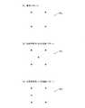
次に、付加情報を識別コードに変換した後、識別コードに対応するM系列符号に変換する。例えば、《0100》の付加情報を付加する場合、図5(a)に示すように、〔0〕〔1〕〔0〕〔0〕の識別コードに置き換えられ、さらに識別コードに対応するM系列符号に置き換えられる。Encoding and decoding are performed using the M-sequence code having the above characteristics. First, the principle of the encoding and decoding method according to the present invention will be described using a one-dimensional M-sequence code as an example.
<When encoding>
First, the correspondence between the identification code and the M-sequence code is determined. Here, the identification code [0] corresponds to the M-sequence code “0100111”, and the identification code [1] corresponds to “1011000” obtained by inverting the M-sequence code.
Next, after converting the additional information into an identification code, it is converted into an M-sequence code corresponding to the identification code. For example, when additional information of << 0100 >> is added, as shown in FIG. 5 (a), it is replaced with an identification code of [0] [1] [0] [0], and further, an M sequence corresponding to the identification code Replaced by a sign.
〈復号化時〉
復号化時には、復号用のM系列符号との一致/不一致を見る。上述したように、M系列符号は自己相関性が高い。よって、M系列符号が同期したところでは符号〈0〉、〈1〉の一致性が高いものとなる。
各識別コード〔0〕〔1〕〔0〕〔1〕が示すM系列符号と、復号用のM系列符号「0100111」とが同期した状態では、図5(b)に示すように、識別コード〔0〕の位置ではM系列符号は全て一致するが、識別コード〔1〕の位置では全て不一致となる。よって、復号用のM系列符号と全部一致するところを識別コード〔1〕、全部不一致となるところを識別コード〔0〕に置き換えることにより、識別コード《0100》を再現することができる。
これに対し、復号用のM系列符号の位置が1ビットでもずれて非同期となると、図5(c)に示すように各識別コードの位置において部分的に符号〈0〉、〈1〉が一致、不一致となる箇所が混在し、無相関となってしまう。その結果、識別コードに置き換えることができず、付加情報を再現することができなくなる。<When decrypting>
At the time of decoding, a match / mismatch with the M-sequence code for decoding is observed. As described above, the M-sequence code has high autocorrelation. Therefore, where the M-sequence code is synchronized, the coincidence of the codes <0> and <1> is high.
In a state where the M-sequence code indicated by each identification code [0] [1] [0] [1] and the decoding M-sequence code “0100111” are synchronized, as shown in FIG. All M-sequence codes match at the position [0], but all do not match at the position of the identification code [1]. Therefore, the identification code << 0100 >> can be reproduced by substituting the identification code [1] for a place that completely matches the decoding M-sequence code and the identification code [0] for a place that does not match all.
On the other hand, when the position of the decoding M-sequence code is shifted by 1 bit and becomes asynchronous, as shown in FIG. 5C, the codes <0> and <1> partially match at the positions of the identification codes. , Mismatched parts are mixed and uncorrelated. As a result, it cannot be replaced with an identification code, and additional information cannot be reproduced.
すなわち、Lビット単位で識別コード〔1〕又は〔0〕のM系列符号と全部一致するところを検出し、一致するM系列符号を対応する識別コード〈0〉又は〈1〉に置き換えることにより、付加情報《0100》を復号することが可能となる。 That is, by detecting where all the identification code [1] or [0] matches the M-sequence code in L bits, and replacing the matching M-sequence code with the corresponding identification code <0> or <1>, It becomes possible to decrypt the additional information << 0100 >>.
符号化部20では、上記符号化及び復号化の原理を利用し、M系列符号を2次元に配列した符号化パターンを用いて符号化、復号化を行う。
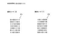
符号化パターンは、図6に示すように「0100111」のM系列符号を1段毎に2ビットシフトさせて2次元的に配列したものを識別コード〔0〕に対応させて符号化パターンP1とし、この符号化パターンP1の反転パターンを識別コード〔1〕に対応させて符号化パターンP2とする。これら符号化パターンP1、P2はパターンメモリ21に記憶されている。The
As shown in FIG. 6, the encoding pattern is an M-sequence code of “0100111” shifted by 2 bits for each stage and arranged two-dimensionally to be an encoding pattern P1 corresponding to the identification code [0]. The inversion pattern of this coding pattern P1 is made to correspond to the identification code [1] to be a coding pattern P2. These encoded patterns P1 and P2 are stored in the
2次元にM系列符号を配列したこれら符号化パターンP1、P2は、図7において矢印で示す何れの方向でもM系列符号を構成することとなり、ランダム性、均等性、自己相関性と、M系列符号が有する特徴を示す。
なお、図7は1段毎にM系列符号を2ビットシフトさせた符号化パターン例を示すものだが、これに限らずシフト量を変更することも可能である。このとき、1段毎のシフト量(つまり上下方向のシフト量)をKビットとすると、Kと左右方向における符号のシフト量(±1)との和K±1及びM系列符号の符号長Lが素の関係を成立させるのであれば、図7に示す符号化パターン例と同様に上下左右・斜め45度方向の全ての方向においてM系列符号となり得る。
特にL=7のとき、7は素数であるので、K=2に限らず、K=3〜5までの任意のシフト量Kとすることができる。このシフト量Kであれば、全ての方向においてM系列符号となる符号化パターンを作成することができる。These encoding patterns P1 and P2 in which M-sequence codes are arranged two-dimensionally constitute an M-sequence code in any direction indicated by an arrow in FIG. 7, and randomness, uniformity, autocorrelation, and M sequence The characteristic which a code has is shown.
FIG. 7 shows an example of an encoding pattern in which the M-sequence code is shifted by 2 bits for each stage. However, the present invention is not limited to this, and the shift amount can be changed. At this time, if the shift amount for each stage (that is, the shift amount in the vertical direction) is K bits, the
In particular, when L = 7, 7 is a prime number, so that it is not limited to K = 2, and any shift amount K from K = 3 to 5 can be set. With this shift amount K, an encoding pattern that becomes an M-sequence code in all directions can be created.
例えば、L=31の場合、31は素数であるので、左右方向で±1ビット、かつ上下方向でK=2〜29ビットまでの任意のシフト量をとることができる。この場合、斜め45度方向(全部で4方向)における符号のシフト量は4方向について±K±1ビットとなり、左右方向におけるシフト量は±1、上下方向におけるシフト量は±Kとなる。何れもが符号長L=31と素の関係にあたるので、図7に示す符号化パターンと同様に上下左右・斜め45度方向の全ての方向においてM系列符号となる2次元符号化パターンを作成することができる。 For example, when L = 31, since 31 is a prime number, an arbitrary shift amount of ± 1 bit in the horizontal direction and K = 2 to 29 bits in the vertical direction can be taken. In this case, the code shift amount in the 45-degree oblique direction (4 directions in total) is ± K ± 1 bits in the four directions, the shift amount in the left-right direction is ± 1, and the shift amount in the up-down direction is ± K. Since both have a prime relationship with the code length L = 31, a two-dimensional coding pattern that is an M-sequence code is created in all directions of up, down, left, right, and 45 degrees, similar to the coding pattern shown in FIG. be able to.
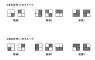
また、図8に示すように中間調の濃度パターン(階調1〜3の濃度パターン)を、M系列符号を構成する〈0〉と〈1〉の符号ごとにグループに分類し、分類した濃度パターンをそのグループの符号〈0〉、〈1〉に対応付けてパターンメモリ21に備えておく。 Further, as shown in FIG. 8, halftone density patterns (gradation patterns of
符号化時、符号化部20はまず付加情報を識別コードに置き換える。次いで、パターンメモリ21から符号化パターンP1、P2を読み出し、置き換えられた識別コードに対応する符号化パターンP1、P2を、付加情報の付加対象である画像(以下、対象画像という)にあてはめる。 At the time of encoding, the
次いで、符号化部20は符号化パターンP1、P2をあてはめた画像部分のうち、M系列符号に置き換える画像部分、つまり符号化対象の画像部分を検出する。なお、符号化パターンP1、P2を構成するL×L個の符号のうち、L個程度の符号に対応する画像部分を符号化対象とすることが好ましい。M系列符号の符号数Lだけあれば、後の復号において一定の繰り返しパターンを検出することが可能となり、復号の精度が向上するためである。 Next, the
符号化対象の画像部分は、中間調の画像部分、或いは対象画像が文字画像を含むのであればこの文字画像の輪郭部分とする。中間調の画像部分の検出は、パターン生成部17から入力される画像の濃度パターンが中間調のものか否かを判別することにより行う。文字画像の輪郭部分は中間調の濃度パターンとなるので、同様に中間調の濃度パターンか否かを判別すればよい。 The image portion to be encoded is a halftone image portion, or the contour portion of the character image if the target image includes a character image. The detection of the halftone image portion is performed by determining whether or not the density pattern of the image input from the
そして、符号化部20は、検出した画像部分を、その画像部分の濃度パターンと同一グループに属する同一階調の他の濃度パターンに置き換える。
対象画像が文字画像を含む場合を例に、図9を参照して具体的に説明する。
図9は、入力画像を誤差拡散処理した後、2×2画素の濃度パターンに置き換えた対象画像g1を示す図である。
符号化部20は、この対象画像g1に《010》《101》の識別コードで示される付加情報c2を付加する場合、この識別コードが示す符号化パターンP1、P2を対象画像g1にあてはめる。あてはめは、M系列符号を構成する符号1つにつき2×2の画素が対応するように行う。あてはめた結果を図10に示す。Then, the
An example in which the target image includes a character image will be specifically described with reference to FIG.
FIG. 9 is a diagram illustrating the target image g1 that has been subjected to error diffusion processing on the input image and replaced with a density pattern of 2 × 2 pixels.
When adding the additional information c2 indicated by the identification code of “010” and “101” to the target image g1, the
次に、符号化部20は、対象画像g1において文字画像の輪郭部分、つまり中間調の濃度パターンを検出し、あてはめた符号化パターンP1、P2において、前記検出された濃度パターンに対応する符号を特定する。図10において、丸で囲んだ符号が中間調の濃度パターンに対応する符号である。 Next, the
次いで、符号化部20は、特定したM系列符号の符号〈0〉、〈1〉に対応するグループに分類された濃度パターンをパターンメモリ21から読み出す。例えば、対象画像g1から検出されたのが階調2の濃度パターンであって、対応するM系列符号が〈0〉であった場合、図8に示すように〈0〉グループに属する階調2の濃度パターンは3種類ある。その3種類から対象画像g1において検出された濃度パターンを除いた、残りの2種類の濃度パターンのうちの何れかを任意に選択して読み出す。そして、読み出した濃度パターンを対象画像g1から検出された濃度パターンと置き換える。 Next, the
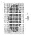
置き換えた結果を、図11に示す。
図11は、文字画像の輪郭部分を構成する中間調の濃度パターンの全部を、同一濃度であって、対応するM系列符号のグループの他の濃度パターンに置き換えた符号化画像g2を示す図である。この図11に示す符号化画像g2がM系列符号によって符号化され、付加情報が付加された画像となる。
符号化部20では、この符号化画像g2を出力する。The result of the replacement is shown in FIG.
FIG. 11 is a diagram showing an encoded image g2 in which all of the halftone density patterns constituting the contour portion of the character image are replaced with other density patterns having the same density and corresponding M-series code groups. is there. The encoded image g2 shown in FIG. 11 is encoded with an M-sequence code, and becomes an image with additional information added.
The
符号化画像g2を復号し、付加情報を取得する場合には、画像処理装置10に復号化部を設ける。そして、復号化部において符号化画像g2の中間調の画像部分、つまり中間調の濃度パターンを検出する。そして、この濃度パターンが属するM系列符号の符号が〈0〉又は〈1〉の何れであるかを判別する。図12は、その判別結果を示す図である。図12において、数字は中間調の濃度パターンが検出された位置を示すとともに、当該濃度パターンが属する符号〈0〉又は〈1〉を示すものである。一方、点は中間調以外の濃度パターンが検出された位置を示している。 When decoding the encoded image g2 and acquiring additional information, the
次いで、復号化部では、符号化画像g2上に符号化パターンP1、P2をそれぞれ走査させ、前記判別した符号〈0〉又は〈1〉と、符号化パターンP1、P2の符号〈0〉又は〈1〉とが全部一致する画像部分を検出する。すなわち、自己相関性の高い符号化パターンP1、P2と全部一致する画像部分は、符号化時に符号化パターンP1、P2があてはめられた画像部分である。次に、復号化部において検出した画像部分を符号化パターンP1、P2が示す識別コードに置き換えることにより、《010》、《101》の付加情報c1を求めることができる。 Next, the decoding unit scans the encoded patterns P1 and P2 on the encoded image g2, respectively, and determines the determined code <0> or <1> and the codes <0> or <1 of the encoded patterns P1 and P2. 1> is detected. In other words, the image portions that match all of the coding patterns P1 and P2 having high autocorrelation are image portions to which the coding patterns P1 and P2 are applied at the time of coding. Next, the additional information c1 of << 010 >> and << 101 >> can be obtained by replacing the image portion detected by the decoding unit with the identification code indicated by the coding patterns P1, P2.
以上のように、第1実施形態によれば、M系列符号を2次元に配列した符号化パターンP1、P2を用いて対象画像の符号化を行い、付加情報を付加する。M系列符号自体、自己相関が高く、これを2次元に配列した符号化パターンP1、P2はより自己相関が高い。よって、対象画像の一部のみ符号化を行うだけで精度の高い復号を行うことが可能となる。 As described above, according to the first embodiment, the target image is encoded using the encoding patterns P1 and P2 in which M-sequence codes are two-dimensionally arranged, and additional information is added. The M-sequence code itself has a high autocorrelation, and the coding patterns P1 and P2 in which these are two-dimensionally arranged have a higher autocorrelation. Therefore, it is possible to perform highly accurate decoding only by encoding only a part of the target image.
また、記録用紙等の媒体に符号化画像g2が出力されると、当該媒体上における復号の起点が不明となる。このような場合であっても、符号化パターンP1、P2を走査し、当該符号化パターンP1、P2との相関性が高いところを検出すれば復号化が可能である。すなわち、M系列符号の高自己相関性という特性によって、符号化時に対象画像に当てはめられた符号化パターンP1、P2と、復号化時に走査される符号化パターンP1、P2との同期をとることができ、符号化パターンP1、P2があてはめられた画像部分を正確に認識することが可能となる。よって、符号化時にその起点を示すマーカーを設ける等の前処理をする必要がないうえ、復号も容易となる。 Further, when the encoded image g2 is output to a medium such as a recording sheet, the starting point of decoding on the medium becomes unknown. Even in such a case, decoding is possible by scanning the coding patterns P1 and P2 and detecting a place having high correlation with the coding patterns P1 and P2. That is, due to the high autocorrelation property of the M-sequence code, the coding patterns P1 and P2 applied to the target image at the time of coding and the coding patterns P1 and P2 scanned at the time of decoding can be synchronized. Thus, it is possible to accurately recognize the image portion to which the encoding patterns P1 and P2 are applied. Therefore, it is not necessary to perform preprocessing such as providing a marker indicating the starting point during encoding, and decoding is facilitated.
また、符号化画像において符号化パターンP1、P2を構成するL×L画素の中で、L個程度の符号が抽出できれば、符号化パターンP1、P2を用いて精度良く復号化することができる。冗長度が大きいため、符号化画像にノイズや画質劣化が生じた場合でも復号化ができ、情報欠損やノイズに対する耐性が高い。 Further, if about L codes can be extracted from the L × L pixels constituting the coding patterns P1 and P2 in the coded image, decoding can be performed with high accuracy using the coding patterns P1 and P2. Since the redundancy is large, decoding can be performed even when noise or image quality deterioration occurs in the encoded image, and resistance to information loss or noise is high.
また、M系列符号はランダムな符号列であるので、符号化画像において付加情報が付加されていることが視認し難い。よって、付加情報として秘匿情報を付加した場合でも、情報漏洩の防止を図ることができる。 Further, since the M-sequence code is a random code string, it is difficult to visually recognize that additional information is added to the encoded image. Therefore, even when confidential information is added as additional information, information leakage can be prevented.
また、本実施形態では符号化時に、誤差拡散処理後の対象画像の濃度パターンを、M系列符号の符号と同一グループに属する他の濃度パターンに置き換えている。中間調の場合、同一階調の濃度パターンは複数種類存在するため、誤差拡散処理ではパターン生成部17においてランダムに一の濃度パターンを選択することにより固定パターン化することを防いでいる。これに加えて、さらに符号化の際に濃度パターンを置き換えることにより、よりランダム性を高めることができ、誤差拡散処理に特有の固定パターンが生じるのを防ぐことができる。 In this embodiment, the density pattern of the target image after the error diffusion process is replaced with another density pattern belonging to the same group as the code of the M-sequence code at the time of encoding. In the case of halftone, there are a plurality of types of density patterns of the same gradation, so that the error diffusion process prevents the
なお、上述した実施形態は本発明の好適な一例であり、これに限定されない。
例えば、誤差拡散処理に限らず、スクリーン処理後の画像に対して符号化を行う場合も、上記と同様の方法により符号化及び復号化が可能である。In addition, embodiment mentioned above is a suitable example of this invention, and is not limited to this.
For example, not only the error diffusion processing but also the case where the image after the screen processing is encoded can be encoded and decoded by the same method as described above.
また、特に誤差拡散処理による濃度パターンの固定化を問題としないのであれば、符号化部20において濃度パターンを同一グループ及び同一階調の他の濃度パターンに置き換える必要はない。 Further, if there is no particular problem with fixing the density pattern by error diffusion processing, it is not necessary for the
さらに、符号化部20における符号化の処理を、パターン生成部17において濃度パターンの生成と同時に行うこととしてもよい。すなわち、パターン生成部17において濃度値に応じた2×2画素の濃度パターンを選択する際に、対象画像g1への符号化パターンP1、P2のあてはめを行い、M系列符号の符号〈0〉、〈1〉に対応する濃度パターンを選択すればよい。 Furthermore, the encoding process in the
〈第2実施形態〉
第2実施形態では、M系列符号を2次元に配置した符号化パターンを用いて、地紋画像を符号化し、付加情報を付加する例を説明する。Second Embodiment
In the second embodiment, an example in which a copy-forgery-inhibited pattern image is encoded using an encoding pattern in which M-sequence codes are arranged two-dimensionally and additional information is added will be described.
図13に、第2実施形態に係る画像処理装置30を示す。
第2実施形態に係る画像処理装置30において、誤差拡散処理についての基本構成は第1実施形態に係る画像処理装置10と同一であり、当該画像処理装置10にさらに地紋画像の生成に係る構成を追加した構成となっている。よって、図13において、第1実施形態に示した画像処理装置10と同一の構成部分には同一の符号を付している。FIG. 13 shows an
In the
すなわち、画像処理装置30は、誤差拡散処理を行うための加算部11、閾値判定部12、濃度演算部13、減算部14、拡散部15、誤差メモリ16、パターン生成部17、パターンメモリ18、地紋画像を生成するための地紋生成部22、パターンメモリ23、符号化を行うための符号化部40、パターンメモリ41を備えて構成されている。
以下、各構成部について説明するが、誤差拡散処理に係る各構成部の処理は第1実施形態と同一であるので、ここでは説明を省略する。That is, the
Hereinafter, although each component will be described, the processing of each component related to the error diffusion process is the same as that of the first embodiment, and thus the description thereof is omitted here.
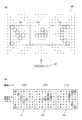
地紋生成部22は、パターンメモリ23から地紋パターンを読み出し、当該地紋パターンを用いて地紋画像を生成する。地紋画像とは、本来の出力対象の画像の背景を構成する画像をいい、例えば背景全体を模様とするものや、文字を構成するもの、透かし文字とするものがある。透かし文字は、地紋画像を印刷した印刷物が複写された際に、透かし文字の地紋画像のみが再現されるように、透かし文字部分とその他の部分との出力条件が調整された地紋画像である。 The background
以下、透かし文字の地紋画像を出力する場合を例に説明する。
図14は、透かし文字の地紋画像例を示す図である。図14に示すように、地紋画像は「複製厳禁」という透かし文字部分と、その他の背景部分とからなる。何れの部分も図15(a)に示す地紋パターンを基本単位として(以下、これを基本パターンP3という)、当該基本パターンP3の繰り返しによって構成されている。ただし、透かし文字部分の地紋パターンの解像度はその他の部分の地紋パターンの解像度よりも大きくなるよう構成されている(例えば、透かし文字部分は300dpi、その他の部分は600dpi等)。
パターンメモリ23には、透かし文字の種類や地紋模様の種類等に応じた基本パターンP3(図15(a)参照)が複数保存されており、地紋生成部22はこの基本パターンP3を読み出して出力画像のサイズ、指定された模様、透かし文字の種類等に合わせた地紋画像を生成する。Hereinafter, a case where a watermark pattern background image is output will be described as an example.
FIG. 14 is a diagram illustrating an example of a watermark pattern copy-forgery-inhibited pattern image. As shown in FIG. 14, the copy-forgery-inhibited pattern image is composed of a watermark character portion “copying strictly prohibited” and other background portions. Each part is configured by repeating the basic pattern P3 with the tint block pattern shown in FIG. 15A as a basic unit (hereinafter referred to as a basic pattern P3). However, the resolution of the background pattern of the watermark character portion is configured to be larger than the resolution of the background pattern of other portions (for example, the watermark character portion is 300 dpi, the other portion is 600 dpi, etc.).
The
符号化部40は、地紋生成部22により生成された地紋画像の符号化を行う。
符号化は、M系列符号を2次元に配列した符号化パターンP1、P2(図6参照)を用いて、地紋画像の全部又は一部の基本パターンを、M系列符号の〈0〉、〈1〉の符号に応じた地紋パターンに置き換えることにより行う。図15(b)に示す地紋パターンP4が符号〈0〉に応じたものであり、図15(c)に示す地紋パターンP5が符号〈1〉に応じたものである。
符号化パターンP1、P2及びM系列符号に応じた地紋パターンP4、P5は、パターンメモリ41に記憶されている。The
Encoding uses coding patterns P1 and P2 (see FIG. 6) in which M-sequence codes are two-dimensionally arranged, and all or part of the basic pattern of the tint block image is converted into <0> and <1 of M-sequence codes. This is done by replacing with a tint block pattern corresponding to the sign of The tint block pattern P4 shown in FIG. 15B corresponds to the code <0>, and the tint block pattern P5 shown in FIG. 15C corresponds to the code <1>.
The tint block patterns P4 and P5 corresponding to the coding patterns P1 and P2 and the M-sequence code are stored in the
符号化時、符号化部40はまず付加情報を識別コードに置き換える。次いで、パターンメモリ41から符号化パターンP1、P2を読み出し、置き換えられた識別コードに応じて読み出した符号化パターンP1、P2を地紋画像にあてはめる。
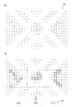
図16(a)に、地紋画像g3(透かし文字の背景部分)の拡大図を示す。図16(a)に示すように、地紋画像g3は基本パターンP3の繰り返しによって模様が構成されている。この地紋画像g3に《001》の識別コードからなる付加情報c2を付加する場合、図16(a)に示すように、識別コード〔0〕、〔0〕、〔1〕に対応する符号化パターンP1、P1、P2(図16(b)参照)を地紋画像g3にあてはめる。At the time of encoding, the
FIG. 16A shows an enlarged view of the copy-forgery-inhibited pattern image g3 (background portion of the watermark character). As shown in FIG. 16A, the background pattern image g3 has a pattern formed by repeating the basic pattern P3. When the additional information c2 including the identification code of “001” is added to the copy-forgery-inhibited pattern image g3, as shown in FIG. 16A, the coding patterns corresponding to the identification codes [0], [0], and [1]. P1, P1, and P2 (see FIG. 16B) are applied to the tint block image g3.
次いで、符号化部40は符号化パターンP1、P2をあてはめた画像領域のうち、M系列符号に置き換える地紋パターン部分、すなわち符号化対象の地紋パターン部分を決定する。符号化対象とする地紋パターン部分は任意に決定することとしてもよいが、L×L個の符号のうち、少なくともL個の地紋パターンを選択することが好ましい。M系列符号の符号数Lだけあれば、後の復号において一定の繰り返しパターンを検出することが可能となり、復号の精度が向上するためである。 Next, the
符号化部40は、決定した地紋パターン部分を、その地紋パターン部分が対応するM系列符号の地紋パターンP4、P5に置き換える。図16(a)では、置き換えを行う地紋パターン部分を丸で囲んで示している。これに対応させて、置き換えを行う地紋パターン部分に対応するM系列符号の符号を、図16(b)において丸で囲んでいる。
置き換えの結果、図17(a)に示すような符号化画像g4が得られる。
符号化部40は、この符号化画像g4を合成部19に出力する。The
As a result of the replacement, an encoded image g4 as shown in FIG. 17A is obtained.
The
合成部19は、パターン生成部17から入力された、濃度パターンからなる出力画像に、符号化部40から入力された符号化画像を合成し、その合成画像を出力する。 The synthesizing
符号化画像g4を復号し、付加情報を取得する場合には、画像処理装置30に復号化部を設ける。そして、復号化部において当該符号化画像g4において基本パターンと異なる地紋パターン部分を検出する。次いで、復号化部において検出した地紋パターンが属するM系列符号が〈0〉又は〈1〉の何れであるかを判別する。図17(b)は検出した地紋パターン部分の位置に、当該地紋パターンが示すM系列符号〈0〉又は〈1〉を表示した図である。 When decoding the encoded image g4 and acquiring additional information, the
次いで、符号化画像g4上に符号化パターンP1、P2を走査させ、前記判別した符号〈0〉、〈1〉と、符号化パターンP1、P2を構成する符号〈0〉、〈1〉とが全部一致する地紋パターン部分を検出する。すなわち、自己相関性が高い符号化パターンP1、P2と全部一致する地紋パターン部分は、符号化時に符号化パターンP1、P2が当てはめられた地紋パターン部分である。
一致する地紋パターン部分が検出されると、復号化部においてその地紋パターン部分を一致した符号化パターンP1、P2が示す識別コードに置き換えることにより、《001》の付加情報c2を求めることができる。Next, the encoded patterns P1 and P2 are scanned on the encoded image g4, and the determined codes <0> and <1> and the codes <0> and <1> constituting the encoded patterns P1 and P2 are obtained. A tint block pattern portion that matches all is detected. In other words, the tint block pattern portions that match all the coding patterns P1 and P2 having high autocorrelation are the tint block pattern portions to which the coding patterns P1 and P2 are applied at the time of coding.
When the matching copy-forgery-inhibited pattern pattern portion is detected, the decoding unit can replace the copy-forgery-inhibited pattern pattern portion with the identification code indicated by the matching encoded patterns P1 and P2, thereby obtaining additional information c2 of << 001 >>.
以上のように、第2実施形態によれば、M系列符号を2次元に配列した符号化パターンP1、P2を用いて地紋画像の符号化を行い、付加情報を付加する。M系列符号自体、自己相関が高く、これを2次元に配列した符号化パターンP1、P2はより自己相関性が高い。よって、符号化パターンP1、P2を用いて符号化を行い、復号化時に符号化パターンP1、P2と全部一致する相関性の高い地紋パターン部分を検出することにより、地紋画像の一部のみ符号化を行うだけで符号化された地紋パターン部分を容易に判別することができる。その結果、精度の高い復号を行うことが可能である。 As described above, according to the second embodiment, the copy-forgery-inhibited pattern image is encoded using the encoding patterns P1 and P2 in which M-sequence codes are two-dimensionally arranged, and additional information is added. The M-sequence code itself has a high autocorrelation, and the coding patterns P1 and P2 in which these are two-dimensionally arranged have a higher autocorrelation. Therefore, coding is performed using the coding patterns P1 and P2, and a portion of the tint block image is coded by detecting a highly correlated tint block pattern portion that matches the coding patterns P1 and P2 at the time of decoding. The encoded tint block pattern portion can be easily discriminated simply by performing. As a result, it is possible to perform highly accurate decoding.
また、記録用紙等の媒体に符号化された地紋画像が出力された場合、復号の起点が不明となる。このような場合であっても、符号化パターンP1、P2を走査し、当該符号化パターンP1、P2との相関性が高いところを検出すれば復号化が可能である。すなわち、M系列符号の高自己相関性という特性によって、地紋画像に当てはめられた符号化パターンP1、P2と同期をとることができ、そのあてはめ位置を正確に認識することが可能となる。よって、復号のために起点を示すマーカーを設ける等の前処理をすることなく、復号が容易となる。 In addition, when an encoded tint block image is output on a medium such as a recording sheet, the starting point of decoding becomes unknown. Even in such a case, decoding is possible by scanning the coding patterns P1 and P2 and detecting a place having high correlation with the coding patterns P1 and P2. That is, due to the high autocorrelation property of the M-sequence code, it is possible to synchronize with the coding patterns P1 and P2 applied to the copy-forgery-inhibited pattern image, and it is possible to accurately recognize the fitting position. Therefore, decoding is facilitated without preprocessing such as providing a marker indicating the starting point for decoding.
また、符号化画像g4において符号化パターンP1、P2を構成するL×L画素の中で、L個程度の符号が抽出できれば、符号化パターンP1、P2を用いて復号化することができる。冗長度が大きいため、符号化画像にノイズや画質劣化が生じた場合でも復号化ができ、情報欠損やノイズに対する耐性が高い。 In addition, if about L codes can be extracted from the L × L pixels constituting the coding patterns P1 and P2 in the coded image g4, decoding can be performed using the coding patterns P1 and P2. Since the redundancy is large, decoding can be performed even when noise or image quality deterioration occurs in the encoded image, and resistance to information loss or noise is high.
また、符号化の際には地紋の基本パターンP3をM系列符号に応じた地紋パターンP4、P5に置き換えるが、基本パターンP3と地紋パターンP4、P5はドット1つ分の差という微細な差異しかないため、符号化画像g4において付加情報が付加されていることは視認し難い。よって、付加情報として秘匿情報を付加した場合でも、当該秘匿情報の視覚による認識はできず、表面上の情報漏洩の防止を図ることができる。 In the encoding, the basic pattern P3 of the tint block is replaced with the tint block patterns P4 and P5 corresponding to the M-sequence code. The basic pattern P3 and the tint block patterns P4 and P5 have only a minute difference of one dot. Therefore, it is difficult to visually recognize that additional information is added in the encoded image g4. Therefore, even when confidential information is added as additional information, the confidential information cannot be visually recognized, and information leakage on the surface can be prevented.
また、地紋画像に付加情報を付加する場合、本来出力対象とする対象画像を符号化のために処理する必要がないので、対象画像を正確に再現しながら、付加情報を付加することが可能となる。 In addition, when additional information is added to the copy-forgery-inhibited pattern image, it is not necessary to process the target image that is originally an output target for encoding. Therefore, additional information can be added while accurately reproducing the target image. Become.
また、地紋画像の透かし文字の背景部分に付加情報を付加した場合、その地紋画像が印刷された記録用紙(原本)を複写すると、その複写物(副本)において当該背景部分の地紋画像は失われる。よって、付加情報の復号ができるかどうかによって印刷物が原本であるか否かを判別することができる。近年では印刷技術の発達により見た目には原本との差異がわからないほど精巧な複写物を作成することが可能である。このような場合でも、地紋画像にM系列符号による符号化を行っておけば、真贋判定を行うことが可能となる。 Further, when additional information is added to the background portion of the watermark character of the copy-forgery-inhibited pattern image, if the recording paper (original) on which the copy-forgery-inhibited pattern image is printed is copied, the copy-forgery-inhibited pattern image in the background portion is lost in the copy (second copy). . Therefore, it can be determined whether or not the printed matter is the original depending on whether or not the additional information can be decoded. In recent years, due to the development of printing technology, it is possible to create a copy that is so elaborate that the difference from the original is not apparent. Even in such a case, if the background pattern image is encoded with the M-sequence code, the authenticity determination can be performed.
なお、上記実施形態は本発明の好適な一例であり、これに限定されない。
例えば、上記説明では地紋画像の背景部分の符号化を行う例を説明したが、これに限らず、地紋画像の透かし文字部分の符号化を行うこととしてもよい。また、地紋画像を出力しない場合には、故意に背景に中間調の画像を設け、当該画像の符号化を行うこととしてもよい。In addition, the said embodiment is a suitable example of this invention, and is not limited to this.
For example, in the above description, an example in which the background portion of the tint block image is encoded has been described. However, the present invention is not limited thereto, and the watermark character portion of the tint block image may be encoded. In addition, when a copy-forgery-inhibited pattern image is not output, a halftone image may be intentionally provided in the background, and the image may be encoded.
また、地紋画像ではなく、2次元バー識別コードに用いられるようなQR符号のパターン画像において上記符号化パターンP1、P2による符号化を行うこととしてもよい。この場合、符号化パターンP1、P2を用いることでQR符号を一見しただけでは付加情報を把握できないようにすることができるうえ、さらにQR符号自体に誤り訂正の機能があるため、復号に際してのノイズや情報欠落に対する耐性が向上する。 Further, instead of the copy-forgery-inhibited pattern image, a pattern image of a QR code as used for a two-dimensional bar identification code may be encoded by the encoding patterns P1 and P2. In this case, by using the coding patterns P1 and P2, it is possible to prevent the additional information from being grasped only by looking at the QR code. Further, since the QR code itself has a function of error correction, noise during decoding can be prevented. And resistance to missing information is improved.
10 画像処理装置
11 加算部
12 閾値判定部
13 濃度演算部
14 減算部
15 拡散部
16 誤差メモリ
17 パターン生成部
20 符号化部
21 パターンメモリ
30 画像処理装置
19 合成部
22 地紋生成部
40 符号化部
41 パターンメモリDESCRIPTION OF
Claims (12)
Translated fromJapanese符号化対象の対象画像に付加する付加情報を識別コードに変換するコード変換手段と、
前記変換された識別コードに対応する符号化パターンを前記記憶手段から取得して前記対象画像にあてはめ、あてはめた画像部分の全部又は一部を、対応する符号化パターンのM系列符号に応じて符号化する符号化手段と、
を備えることを特徴とする画像処理装置。Storage means for storing, for each identification code, an encoding pattern in which M-sequence codes are arranged two-dimensionally;
Code conversion means for converting additional information added to the target image to be encoded into an identification code;
An encoding pattern corresponding to the converted identification code is acquired from the storage means and applied to the target image, and all or part of the applied image portion is encoded according to the M-sequence code of the corresponding encoding pattern. Encoding means for
An image processing apparatus comprising:
前記符号化手段は、前記符号化パターンをあてはめた画像部分のうち、中間調の画像部分の濃度パターンを、その中間調の画像部分に対応するM系列符号に応じた濃度パターンに置き換えることにより、符号化を行うことを特徴とする請求項1に記載の画像処理装置。The target image is a multi-valued image;
The encoding means replaces the density pattern of the halftone image portion of the image portion to which the encoding pattern is applied with a density pattern corresponding to the M-sequence code corresponding to the halftone image portion, The image processing apparatus according to claim 1, wherein encoding is performed.
前記符号化手段は、前記符号化パターンをあてはめた画像部分のうち、文字画像の輪郭部分の濃度パターンを、その輪郭部分に対応するM系列符号に応じた濃度パターンに置き換えることにより、符号化を行うことを特徴とする請求項1に記載の画像処理装置。The target image includes a character image,
The encoding means performs encoding by replacing the density pattern of the contour portion of the character image in the image portion to which the encoding pattern is applied with a density pattern corresponding to the M-sequence code corresponding to the contour portion. The image processing apparatus according to claim 1, wherein the image processing apparatus performs the processing.
前記符号化手段は、前記符号化パターンをあてはめた画像部分の全部又は一部の地紋パターンを、その全部又は一部に対応するM系列符号に応じた地紋パターンに置き換えることにより、符号化を行うことを特徴とする請求項1に記載の画像処理装置。The target image is a copy-forgery-inhibited pattern image formed by repeating a copy-forgery-inhibited pattern.
The encoding means performs encoding by replacing all or part of the tint block pattern of the image portion to which the coding pattern is applied with a tint block pattern corresponding to the M sequence code corresponding to all or part of the pattern pattern. The image processing apparatus according to claim 1.
請求項1〜5の何れか一項に記載の画像処理装置によって符号化された符号化画像に対し、前記記憶された符号化パターンを走査させ、当該符号化パターンのM系列符号と一致する画像部分を検出し、一致する符号化パターンに対応する識別コードに変換する復号化手段と、
前記変換された識別コードを前記符号化画像に付加された付加情報に変換し、当該付加情報を出力するコード変換手段と、
を備えることを特徴とする画像処理装置。Storage means for storing, for each identification code, an encoding pattern in which M-sequence codes are arranged two-dimensionally;
An image that matches the M-sequence code of the encoded pattern by scanning the stored encoded pattern with respect to the encoded image encoded by the image processing device according to any one of claims 1 to 5. Decoding means for detecting the part and converting it into an identification code corresponding to the matching coding pattern;
Code conversion means for converting the converted identification code into additional information added to the encoded image and outputting the additional information;
An image processing apparatus comprising:
M系列符号を2次元に配置した符号化パターンが識別コードごとに記憶された記憶手段から、前記変換された識別コードに対応する符号化パターンを取得して前記対象画像にあてはめ、あてはめた画像部分の全部又は一部を、対応する符号化パターンのM系列符号に応じて符号化する符号化工程と、
を含むことを特徴とする符号化方法。A code conversion step for converting additional information to be added to the target image to be encoded into an identification code;
An image portion obtained by obtaining an encoding pattern corresponding to the converted identification code from a storage means in which an encoding pattern in which an M-sequence code is arranged in two dimensions is stored for each identification code, and applying the acquired encoding pattern to the target image. An encoding step of encoding all or a part of the signal in accordance with the M-sequence code of the corresponding encoding pattern;
The encoding method characterized by including.
前記符号化工程では、前記符号化パターンをあてはめた画像部分のうち、中間調の画像部分の濃度パターンを、その中間調の画像部分に対応するM系列符号に応じた濃度パターンに置き換えることにより、符号化を行うことを特徴とする請求項7に記載の符号化方法。The target image is a multi-valued image;
In the encoding step, among the image portions to which the encoding pattern is applied, by replacing the density pattern of the halftone image portion with a density pattern corresponding to the M series code corresponding to the halftone image portion, The encoding method according to claim 7, wherein encoding is performed.
前記符号化工程では、前記符号化パターンをあてはめた画像部分のうち、文字画像の輪郭部分の濃度パターンを、その輪郭部分に対応するM系列符号に応じた濃度パターンに置き換えることにより、符号化を行うことを特徴とする請求項7に記載の符号化方法。The target image includes a character image,
In the encoding step, encoding is performed by replacing the density pattern of the outline part of the character image in the image part to which the encoding pattern is applied with a density pattern corresponding to the M-sequence code corresponding to the outline part. The encoding method according to claim 7, wherein the encoding method is performed.
前記符号化工程では、前記符号化パターンをあてはめた画像部分の全部又は一部の地紋パターンを、その全部又は一部に対応するM系列符号に応じた地紋パターンに置き換えることにより、符号化を行うことを特徴とする請求項7に記載の符号化方法。The target image is a copy-forgery-inhibited pattern image formed by repeating a copy-forgery-inhibited pattern.
In the encoding step, encoding is performed by replacing all or part of the tint block pattern of the image portion to which the coding pattern is applied with a tint block pattern corresponding to the M sequence code corresponding to all or part of the pattern pattern. The encoding method according to claim 7.
前記変換された識別コードを前記符号化画像に付加された付加情報に変換し、当該付加情報を出力するコード変換工程と、
を含むことを特徴とする復号化方法。An encoding pattern in which M-sequence codes are arranged two-dimensionally with respect to an encoded image encoded by the encoding method according to any one of claims 7 to 11, and created for each identification code A decoding step of scanning the coding pattern, detecting an image portion that matches the M-sequence code of the coding pattern, and converting it to an identification code corresponding to the matching coding pattern;
A code conversion step of converting the converted identification code into additional information added to the encoded image and outputting the additional information;
The decoding method characterized by including.
Priority Applications (1)
| Application Number | Priority Date | Filing Date | Title |
|---|---|---|---|
| JP2006327876AJP4725498B2 (en) | 2006-12-05 | 2006-12-05 | Image processing apparatus, encoding method, and decoding method |
Applications Claiming Priority (1)
| Application Number | Priority Date | Filing Date | Title |
|---|---|---|---|
| JP2006327876AJP4725498B2 (en) | 2006-12-05 | 2006-12-05 | Image processing apparatus, encoding method, and decoding method |
Publications (2)
| Publication Number | Publication Date |
|---|---|
| JP2008141640A JP2008141640A (en) | 2008-06-19 |
| JP4725498B2true JP4725498B2 (en) | 2011-07-13 |
Family
ID=39602617
Family Applications (1)
| Application Number | Title | Priority Date | Filing Date |
|---|---|---|---|
| JP2006327876AExpired - Fee RelatedJP4725498B2 (en) | 2006-12-05 | 2006-12-05 | Image processing apparatus, encoding method, and decoding method |
Country Status (1)
| Country | Link |
|---|---|
| JP (1) | JP4725498B2 (en) |
Family Cites Families (3)
| Publication number | Priority date | Publication date | Assignee | Title |
|---|---|---|---|---|
| JPH07223339A (en)* | 1994-02-10 | 1995-08-22 | Canon Inc | Code printing method and device, code reproducing method and device, and printed matter thereof |
| JP2005223574A (en)* | 2004-02-05 | 2005-08-18 | Fuji Xerox Co Ltd | Image processing method and image processing apparatus |
| JP4134992B2 (en)* | 2005-03-08 | 2008-08-20 | 沖電気工業株式会社 | Watermark information detection apparatus, watermark information embedding apparatus, watermark information detection method, and watermark information embedding method |
- 2006
- 2006-12-05JPJP2006327876Apatent/JP4725498B2/ennot_activeExpired - Fee Related
Also Published As
| Publication number | Publication date |
|---|---|
| JP2008141640A (en) | 2008-06-19 |
Similar Documents
| Publication | Publication Date | Title |
|---|---|---|
| JP4187749B2 (en) | Halftone watermarking and related applications | |
| JP4000316B2 (en) | Generation of figure codes by halftoning using embedded figure coding | |
| US6993154B2 (en) | Measuring digital watermark strength using error correction coding metrics | |
| JP3898519B2 (en) | Process for generating certifiable color documents | |
| JP4218920B2 (en) | Image processing apparatus, image processing method, and storage medium | |
| US6694041B1 (en) | Halftone watermarking and related applications | |
| US5790703A (en) | Digital watermarking using conjugate halftone screens | |
| US6456393B1 (en) | Information embedding in document copies | |
| JP4400565B2 (en) | Watermark information embedding device and watermark information detection device | |
| JP4173994B2 (en) | Detection of halftone modulation embedded in an image | |
| JP2001218006A (en) | Image processing apparatus, image processing method, and storage medium | |
| JP4874221B2 (en) | Method and system for generating color images | |
| JP4977103B2 (en) | Print document authentication method, computer program product, and data processing system | |
| KR100357679B1 (en) | Image processing apparatus and method, and storage medium | |
| WO2005094058A1 (en) | Printing medium quality adjusting system, examining watermark medium output device, watermark quality examining device, adjusted watermark medium output device, printing medium quality adjusting method, and examining watermark medium | |
| JPH11261806A (en) | Method for embedding information readable by human being into image | |
| JP2005136981A (en) | Information embedding in images | |
| JP4725498B2 (en) | Image processing apparatus, encoding method, and decoding method | |
| JP2004363990A (en) | Image tampering detection device and method for restoring stored data | |
| JP2003219148A (en) | Digital watermark embedding method, digital watermark detection method, digital watermark embedding device, digital watermark detection device, storage medium storing digital watermark embedding program, storage medium storing digital watermark detection program, and digital watermark system | |
| JP2001103281A (en) | Image processing apparatus and image processing method | |
| JP2006166201A (en) | Image forming apparatus | |
| JP2006270434A (en) | Method and device for embedding information, and method and device for restoring information | |
| JP2001292301A (en) | Image processing apparatus, image processing method, and storage medium | |
| Mayer et al. | Informed Coded Modulation and Host Rejection cTechniques for Color Inkjet Hardcopy Watermarking in the Spatial Domain |
Legal Events
| Date | Code | Title | Description |
|---|---|---|---|
| A621 | Written request for application examination | Free format text:JAPANESE INTERMEDIATE CODE: A621 Effective date:20090806 | |
| A521 | Written amendment | Free format text:JAPANESE INTERMEDIATE CODE: A523 Effective date:20091104 | |
| A977 | Report on retrieval | Free format text:JAPANESE INTERMEDIATE CODE: A971007 Effective date:20110228 | |
| A01 | Written decision to grant a patent or to grant a registration (utility model) | Free format text:JAPANESE INTERMEDIATE CODE: A01 Effective date:20110315 | |
| A61 | First payment of annual fees (during grant procedure) | Free format text:JAPANESE INTERMEDIATE CODE: A61 Effective date:20110328 | |
| R150 | Certificate of patent or registration of utility model | Free format text:JAPANESE INTERMEDIATE CODE: R150 | |
| FPAY | Renewal fee payment (event date is renewal date of database) | Free format text:PAYMENT UNTIL: 20140422 Year of fee payment:3 | |
| S111 | Request for change of ownership or part of ownership | Free format text:JAPANESE INTERMEDIATE CODE: R313111 | |
| R350 | Written notification of registration of transfer | Free format text:JAPANESE INTERMEDIATE CODE: R350 | |
| LAPS | Cancellation because of no payment of annual fees |