JP4725370B2 - Container branching device - Google Patents
Container branching deviceDownload PDFInfo
- Publication number
- JP4725370B2 JP4725370B2JP2006059273AJP2006059273AJP4725370B2JP 4725370 B2JP4725370 B2JP 4725370B2JP 2006059273 AJP2006059273 AJP 2006059273AJP 2006059273 AJP2006059273 AJP 2006059273AJP 4725370 B2JP4725370 B2JP 4725370B2
- Authority
- JP
- Japan
- Prior art keywords
- conveyor
- containers
- supply
- discharge
- transport
- Prior art date
- Legal status (The legal status is an assumption and is not a legal conclusion. Google has not performed a legal analysis and makes no representation as to the accuracy of the status listed.)
- Active
Links
Images


Landscapes
- Branching, Merging, And Special Transfer Between Conveyors (AREA)
Description
Translated fromJapanese本発明は、2列のコンベヤによって供給されてきた容器を一旦集合させた後、再度2列のコンベヤに分岐させる容器の分岐装置に関するものである。 The present invention relates to a container branching device that once gathers containers supplied by a two-row conveyor and then branches them again to a two-row conveyor.
飲料の製造ラインでは、フィラとその下流側に配置されたラベラのように上流側の処理装置が下流側の処理装置と比較して高速の場合には、フィラで液体が充填された容器を2列に分岐させて2台のラベラによって処理を行う場合がある。2列に分岐されて処理された容器は、下流のケーサ等の処理装置に搬送されるが、ライン稼働率の低下を防止するため、途中にアキュームコンベヤを配置することが一般的である。その場合には、2列に分岐されて搬送された容器をアキュームコンベヤに載せ、その後、再度2列に分岐する必要がある。このように2列で供給される容器を一旦集積した後、再度2列に分岐させる装置はすでに知られている(例えば、特許文献1参照) In the beverage production line, when the upstream processing device is faster than the downstream processing device, such as a filler and a labeler disposed downstream thereof, two containers filled with liquid with the filler are used. There are cases where processing is performed by two labelers after branching into a row. The containers branched and processed in two rows are transported to a processing apparatus such as a downstream caser. However, in order to prevent a reduction in the line operation rate, it is common to place an accumulator on the way. In that case, it is necessary to place the containers branched and conveyed in two rows on the accumulation conveyor, and then branch again in two rows. An apparatus that once accumulates containers supplied in two rows in this way and then branches them again into two rows is already known (see, for example, Patent Document 1).
特許文献1に記載された装置は、2列の上流側搬送路から搬送されるワークを、導入コンベヤを介して集合させる集積コンベヤと、この集積コンベヤの下流側に順に接続された2列の第1コンベヤおよび2列の第2コンベヤと、これら各第2コンベヤの外側面に接続された2列の第3コンベヤと、これら各コンベヤの搬送速度を制御する搬送制御手段とを備え、さらに、前記2列の第3コンベヤにそれぞれ接続された下流搬送路に、ワークの数量を計数するカウンタが設けられている。 The apparatus described in
前記装置では、両側の下流搬送路を搬送されるワークの数量が異なっている場合には、搬送制御手段によって、カウンタの数量がほぼ同一となるように前記各コンベヤの搬送速度を制御するようにしている。
前記従来の搬送装置の構成では、各コンベヤの速度制御が複雑であり、また、集積コンベヤへの容器の供給が、一方の側部からだけ行われるので、上流側からの供給量が少ない時には、下流側の2列のコンベヤに容器を均等に振り分けることが難しいという問題があった。 In the configuration of the conventional conveying apparatus, the speed control of each conveyor is complicated, and the supply of containers to the accumulation conveyor is performed only from one side, so when the supply amount from the upstream side is small, There was a problem that it was difficult to evenly distribute the containers to the two downstream conveyors.
本発明は、容器を搬送する搬送コンベヤと、この搬送コンベヤの搬送方向両側から容器を供給する第1供給コンベヤおよび第2供給コンベヤと、前記搬送コンベヤの両側に配置され、搬送コンベヤ上を搬送される容器に係合してその搬送方向を変更可能な一対の揺動ガイドと、これら揺動ガイドの作動を制御する制御手段と、前記搬送コンベヤに接続され、容器を下流へ搬送する第1排出コンベヤおよび第2排出コンベヤと、これら第1排出コンベヤと第2排出コンベヤの中間に配置され、前記搬送コンベヤによって搬送されてきた容器をいずれかの排出コンベヤに案内する分岐ガイドと、前記第1供給コンベヤおよび第2供給コンベヤから供給される容器の供給状態を検出する第1容器検出手段および第2容器検出手段と、前記揺動ガイドの上流側に設けられ、前記第1もしくは第2供給コンベヤから供給される容器に係合して多列に振り分ける揺動可能な一対の振り分けガイドとを備え、前記2列の供給コンベヤから容器が供給されている時には、前記一対の揺動ガイドを容器に係合しない位置に後退させ、あるいは、両揺動ガイドを搬送コンベヤの内方へ前進させ、また、いずれか一方の供給コンベヤからの容器の供給が停止した場合には、容器を供給している供給コンベヤ側の揺動ガイドにより容器の搬送方向を変更して、前記分岐ガイドへ向けて搬送させることを特徴とするものである。The present invention includes a transport conveyor for transporting containers, a first supply conveyor and a second supply conveyor for supplying containers from both sides of the transport direction of the transport conveyor, and both sides of the transport conveyor, and is transported on the transport conveyor. A pair of swing guides that can be engaged with a container to change its transport direction, control means for controlling the operation of these swing guides, and a first discharge connected to the transport conveyor and transporting the containers downstream A conveyor and a second discharge conveyor, a branch guide disposed between the first discharge conveyor and the second discharge conveyor and guiding the containers conveyed by the transfer conveyor to one of the discharge conveyors, and the first supply a first container detecting means and the second container detecting means for detecting a state of supply of containers to be supplied from the conveyor and a second feedconveyor, the swing guide Provided upstream, anda swingable pair of sorting guide allocation to engage multiple rows in a container supplied from the first or the second supply conveyor, the containers from two rows feed conveyor supply The pair of swing guides are retracted to a position where they do not engage with the containers, or both swing guides are advanced inward of the transport conveyor, and the containers from either of the supply conveyors When the supply stops, the container conveyance direction is changed by the swing guide on the supply conveyor side that supplies the containers, and the containers are conveyed toward the branch guide.
また、請求項2に記載の発明は、容器を搬送する搬送コンベヤと、この搬送コンベヤの搬送方向両側から容器を供給する第1供給コンベヤおよび第2供給コンベヤと、前記搬送コンベヤの両側に配置され、搬送コンベヤ上を搬送される容器に係合してその搬送方向を変更可能な一対の揺動ガイドと、これら揺動ガイドの作動を制御する制御手段と、前記搬送コンベヤに接続され、容器を下流へ搬送する第1排出コンベヤおよび第2排出コンベヤと、これら第1排出コンベヤと第2排出コンベヤの中間に配置され、前記搬送コンベヤによって搬送されてきた容器をいずれかの排出コンベヤに案内する分岐ガイドと、前記第1排出コンベヤが満杯になったことを検出する第1満杯検出手段と、第2排出コンベヤが満杯になったことを検出する第2満杯検出手段と、前記揺動ガイドの上流側に設けられ、前記第1もしくは第2供給コンベヤから供給される容器に係合して多列に振り分ける揺動可能な一対の振り分けガイドとを備え、前記両排出コンベヤがいずれも満杯でない時には、前記一対の揺動ガイドの動作位置によって、前記第1排出コンベヤおよび第2排出コンベヤにほぼ均等に容器を振り分け、いずれか一方の排出コンベヤが満杯の時には、前記揺動ガイドによって、満杯でない排出コンベヤに全ての容器を送ることを特徴とするものである。The invention according to
さらに、請求項3に記載の発明は、容器を搬送する搬送コンベヤと、この搬送コンベヤの搬送方向両側から容器を供給する第1供給コンベヤおよび第2供給コンベヤと、前記搬送コンベヤの両側に配置され、搬送コンベヤ上を搬送される容器に係合してその搬送方向を変更可能な一対の揺動ガイドと、これら揺動ガイドの作動を制御する制御手段と、前記搬送コンベヤに接続され、容器を下流へ搬送する第1排出コンベヤおよび第2排出コンベヤと、これら第1排出コンベヤと第2排出コンベヤの中間に配置され、前記搬送コンベヤによって搬送されてきた容器をいずれかの排出コンベヤに案内する分岐ガイドと、前記第1供給コンベヤおよび第2供給コンベヤから供給される容器の供給状態を検出する第1容器検出手段および第2容器検出手段と、前記第1排出コンベヤが満杯になったことを検出する第1満杯検出手段と、第2排出コンベヤが満杯になったことを検出する第2満杯検出手段と、前記揺動ガイドの上流側に設けられ、前記第1もしくは第2供給コンベヤから供給される容器に係合して多列に振り分ける揺動可能な一対の振り分けガイドとを備え、前記2列の供給コンベヤから容器が供給されるとともに、前記両排出コンベヤがいずれも満杯でない時には、一対の揺動ガイドを容器に係合しない位置に後退させ、あるいは、両揺動ガイドを搬送コンベヤの内方へ前進させ、また、いずれか一方の供給コンベヤからの容器の供給が停止し、かつ、前記両排出コンベヤがいずれも満杯でない時には、容器を供給している供給コンベヤ側の揺動ガイドにより容器の搬送方向を変更して、前記分岐ガイドへ向けて搬送させ、2列の供給コンベヤから容器が供給され、かつ、一方の排出コンベヤが満杯の時には、満杯の排出コンベヤ側の揺動ガイドによって、全ての容器を満杯でない排出コンベヤ側に送り、一方の供給コンベヤから容器の供給が停止されるとともに、この供給コンベヤと同一側の排出コンベヤが満杯の時は、揺動ガイドを容器に係合しない位置に後退させ、一方の供給コンベヤから容器の供給が停止されるとともに、この供給コンベヤと逆側の排出コンベヤが満杯の時は、容器を供給している供給コンベヤ側の揺動ガイドによって、全ての容器を逆側の排出コンベヤに送ることを特徴とするものである。Furthermore, the invention according to claim 3 is arranged on both sides of the transport conveyor for transporting the containers, the first supply conveyor and the second supply conveyor for supplying the containers from both sides of the transport direction of the transport conveyor, and the transport conveyor. A pair of swing guides that can be engaged with a container transported on the transport conveyor and change its transport direction, control means for controlling the operation of these swing guides, and connected to the transport conveyor, A first discharge conveyor and a second discharge conveyor that are transported downstream, and a branch that is disposed between the first discharge conveyor and the second discharge conveyor and guides the containers that have been transported by the transport conveyor to one of the discharge conveyors. Guide, first container detection means for detecting the supply state of the containers supplied from the first supply conveyor and the second supply conveyor, and second container detection Stage and a first full detection means for detecting that said first discharge conveyor is full, the second full detecting means for detecting that the second discharge conveyor isfull, upstream of the swing guide A pair of swinging guides that are providedon the side and engage with the containers supplied from the first or second supply conveyor to distribute them in multiple rows, and the containers are supplied from the two rows of supply conveyors. When both the discharge conveyors are not full, the pair of swing guides are retracted to a position where they are not engaged with the container, or both the swing guides are advanced inward of the transport conveyor, When the supply of containers from one of the supply conveyors is stopped and both the discharge conveyors are not full, the container conveyance direction is determined by the swinging guide on the supply conveyor side supplying the containers. When the container is supplied from two rows of supply conveyors and one of the discharge conveyors is full, all the containers are moved by the swing guide on the side of the full discharge conveyor. When it is fed to the discharge conveyor side that is not full and the supply of containers from one supply conveyor is stopped, the discharge guide on the same side as this supply conveyor is full. When the supply of containers from one supply conveyor is stopped and the discharge conveyor on the opposite side of this supply conveyor is full, all the containers are reversed by the swinging guide on the supply conveyor side supplying the containers. It is characterized by being sent to the discharge conveyor on the side.
搬送コンベヤの左右両側に配置した一対の揺動ガイドによって、容器の搬送方向を変更することにより、分岐される2列の排出コンベヤにほぼ均等に容器を振り分けることができる。また、上流側の2列の供給コンベヤの一方からだけ容器が供給される場合でも、下流側の2列の排出コンベヤに容器を均等に振り分けることができる。しかも、下流側の排出コンベヤの一方が満杯になった場合でも、他方の排出コンベヤに確実に送り出すことができる。 By changing the conveyance direction of the containers with a pair of swing guides arranged on the left and right sides of the conveyance conveyor, the containers can be distributed almost evenly to the two rows of discharge conveyors branched. Further, even when containers are supplied only from one of the two upstream supply conveyors, the containers can be evenly distributed to the two downstream discharge conveyors. Moreover, even when one of the downstream discharge conveyors becomes full, it can be reliably sent to the other discharge conveyor.
容器を搬送する搬送コンベヤと、この搬送コンベヤの左右両側から容器を供給する2本の供給コンベヤと、前記搬送コンベヤの下流側に接続され、前記容器を下流側に搬送する2列の排出コンベヤと、2列の供給コンベヤの容器供給状態をそれぞれ検出する容器検出手段と、2列の排出コンベヤが満杯であることをそれぞれ検出する満杯検出手段と、前記搬送コンベヤの両側に配置され、搬送される容器に係合して搬送方向を変更可能な一対の揺動ガイドと、これら揺動ガイドの作動を制御する制御手段とを備えることにより、2列の排出コンベヤに均等に振り分けたり、いずれかの供給コンベヤが容器の供給を停止し、または、いずれかの排出コンベヤが満杯になった場合でも、確実に下流側の排出コンベヤに送るという目的を達成する。 A transport conveyor for transporting containers, two supply conveyors for supplying containers from the left and right sides of the transport conveyor, two rows of discharge conveyors connected to the downstream side of the transport conveyor and transporting the containers to the downstream side, Container detection means for detecting the container supply state of each of the two rows of supply conveyors, full detection means for detecting that the two rows of discharge conveyors are full, respectively, and disposed on both sides of the transfer conveyor and transported By providing a pair of swing guides that can change the transport direction by engaging with the containers and a control means for controlling the operation of these swing guides, the two transport conveyors can be evenly distributed, The objective is to ensure that the supply conveyor stops feeding the containers, or even if one of the discharge conveyors is full, it is sent to the downstream discharge conveyor.
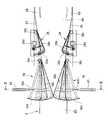
以下、図面に示す実施例により本発明を説明する。図1は本発明の一実施例に係る容器の分岐装置の全体の構成を示す平面図、図2はこの容器の分岐装置の要部を拡大して示す図、図3は図2のIII−III線に沿う断面図である。この容器の分岐装置は、上流側に配置された容器処理装置(図示せず)で処理された容器2が、2本の供給コンベヤ(第1供給コンベヤ4および第2供給コンベヤ6)によって搬送され、搬送コンベヤ8に供給される。これら容器2は、搬送コンベヤ8によって搬送された後、2列に分岐されて平行する2本の排出コンベヤ(第1排出コンベヤ10および第2排出コンベヤ12)によって下流側に配置された別の容器処理装置(図示せず)に送られる。なお、この実施例の搬送コンベヤ8は、下流側の容器処理装置でトラブルがあった場合等に一時的に容器2を貯留することができるアキューム機能を有している。 Hereinafter, the present invention will be described with reference to embodiments shown in the drawings. FIG. 1 is a plan view showing the overall structure of a container branching apparatus according to an embodiment of the present invention, FIG. 2 is an enlarged view showing the main part of the container branching apparatus, and FIG. It is sectional drawing which follows an III line. In this container branching apparatus,
2本の供給コンベヤ4、6は、その下流部が搬送コンベヤ8の上流部8Aの両側に平行に配置されており、図1の右下方に設置されている図示しないラベラ等の容器処理装置で処理された容器2が2本の供給コンベヤ4、6によって1列ずつ搬送され、搬送コンベヤ8の上流部8Aに、搬送方向の左右両側から供給される。各供給コンベヤ4、6は、上流部4A、6Aが第1モータ14および第2モータ16によってそれぞれ駆動され、湾曲部から搬送コンベヤ8の両側に至る下流部4B、6Bが、第3モータ18および第4モータ20によってそれぞれ駆動される。 The two
2本の供給コンベヤ4、6の下流部4B、6B間に搬送コンベヤ8の上流部8Aが配置されており、これら両側の供給コンベヤ4、6上には、搬送されてきた容器2を搬送コンベヤ8の上流部8Aに乗り移らせるガイド部材22、24と、供給コンベヤ4、6から搬送コンベヤ8上に乗り移る容器2に係合して、その搬送方向を変更可能な振り分けガイド26、28がそれぞれ配置されている。 An
各振り分けガイド26、28は、L字状に折り曲げられた板体から構成されており、折り曲げられた短辺26a、28aを搬送方向の下流側に向け、かつ、長辺26b、28bを搬送コンベヤ8の内部側に向けている。これら振り分けガイド26、28は、上流側(図1および図2の右側)に設けられた支点26c、28cを中心として搬送コンベヤ8の内方へ向けて揺動することにより、2本の供給コンベヤ4、6からそれぞれ1列で搬送されてきた容器2(後に説明する図3参照)に係合して、これら容器2を多列に振り分けるようになっている。両振り分けガイド26、28は、それぞれモータ26d、28dによって偏心軸を回転させることにより所定角度往復揺動する。この実施例では、両振り分けガイド26、28は同時に内方へ揺動し、また、同時に外方へ揺動するようになっているが、必ずしも同じタイミングで揺動する必要はなく、両者26、28の動きにずれを持たしても良い。 Each of the
搬送コンベヤ8は、前記2本の供給コンベヤ4、6の下流部4B、6B間に配置されて、同方向に走行する上流部8Aと、この上流部8Aに連続して直線状に順次設置された第1中流部8Bおよび第2中流部8Cと、これら上流部8A、第1中流部8Bおよび第2中流部8Cに連続し、同方向に同幅で伸びる下流部8Dとから構成されている。この搬送コンベヤ8の下流部8Dは、第1下流部8DAと第2下流部8DBの2列に区分されている。 The
この搬送コンベヤ8は、上流部8Aが第5モータ30により駆動され、第1中流部8Bおよび第2中流部8Cが、それぞれ第6モータ32および第7モータ34によって駆動される。さらに、第1下流部8DAは第8モータ36により、また、第2下流部8DBは第9モータ38によってそれぞれ駆動されるようになっている。搬送コンベヤ8の各部分8A、8B、8C、8DA、8DBは、それぞれ異なるモータ30、32、34、36、38によって駆動されるようになっているので、独立して運転、停止、および速度調整ができるようになっている。なお、この実施例では、2本の供給コンベヤ4、6が搬送コンベヤ8よりも高速で走行するように速度を設定している。 As for this
搬送コンベヤ8の第1下流部8DAに隣接して第1排出コンベヤ10が配置され、第2下流部8DBに隣接して第2排出コンベヤ12が配置されている。つまり、搬送コンベヤ8の平行する第1下流部8DAおよび第2下流部8DBを両側から挟んで、第1排出コンベヤ10および第2排出コンベヤ12が配置されている。第1排出コンベヤ10は、前記搬送コンベヤ8の第1下流部8DAに隣接する上流部10Aと、この上流部10Aの下流寄りの部分の外側(図1の上側)に平行して配置された下流部10Bとを有している。また、第2排出コンベヤ12は、前記搬送コンベヤ8の第2下流部8DBに隣接する上流部12Aと、この上流部12Aの下流寄りの部分の外側(図1の下側)に平行して配置された下流部12Bとを有している。 A
前記2列に区分された搬送コンベヤ8の第1下流部8DAと第2下流部8DB上に跨って、湾曲した分岐ガイド40が配置されている。この分岐ガイド40の頂点40aは、第1下流部8DAと第2下流部8DBの境界上に位置しており、搬送コンベヤ8の上流部8A、第1中流部8Bおよび第2中流部8Cを通って搬送されてきた容器2は、第1下流部8DAと第2下流部8DB上に乗った後、分岐ガイド40によって、第1下流部8DA上の容器2は第1排出コンベヤ10に、また、第2下流部8DB上の容器2は第2排出コンベヤ12にそれぞれ振り分けられる。 A
第1排出コンベヤ10の上流部10A上には、前記搬送コンベヤ8の第1下流部8DA上から乗り移る容器2を案内する傾斜ガイド42が設けられている。この傾斜ガイド42は、前記分岐ガイド40の第1下流部8DA上の部分とほぼ平行する湾曲形状をしており、搬送コンベヤ8の第1下流部8DAから第1排出コンベヤ10に乗り移る容器2は、前記分岐ガイド40とこの傾斜ガイド42によって案内される。第2排出コンベヤ12の上流部12A上には、前記搬送コンベヤ8の第2下流部8DB上から乗り移る容器2を案内する傾斜ガイド44が設けられている。この傾斜ガイド44は、前記分岐ガイド40の第2下流部8DB上の部分とほぼ平行する湾曲形状をしており、搬送コンベヤ8の第2下流部8DBから第2排出コンベヤ12に乗り移る容器2は、前記分岐ガイド40とこの傾斜ガイド44によって案内される。 On the
第1排出コンベヤ10の上流部10Aの下流側部分と下流部10Bの上流側部分とが平行して配置されており、これらの平行する部分の間に、第1排出コンベヤ10の上流部10Aを搬送されてきた容器2を下流部10Bに乗り移らせるガイド部材46、46が設けられている。同様に、第2排出コンベヤ12の上流部12Aの下流側部分と下流部12Bの上流側部分とが平行して配置されており、これらの平行する部分の間に、第2排出コンベヤ12の上流部12Aを搬送されてきた容器2を下流部12Bに乗り移らせるガイド部材48、48が設けられている。 The downstream portion of the
前記第1排出コンベヤ10および第2排出コンベヤ12の上流部10A、12Aは、それぞれ第10モータ50および第11モータ52によって駆動されるようになっており、独立して運転、停止できるようになっている。なお、両排出コンベヤ10、12の下流部10B、12Bは、それぞれ図示しない別のモータによって独立して駆動される。 The
さらに、前記搬送コンベヤ8の上流部8Aの両側には、搬送コンベヤ8上の容器2に係合してその搬送方向を変更することが可能な一対の揺動ガイド(第1揺動ガイド54および第2揺動ガイド56)が設けられている。これら揺動ガイド54、56は、L字状に折り曲げられた板体から構成されており、折り曲げられた短辺54a、56aを搬送方向の下流側に向け、かつ、長辺54b、56bを搬送コンベヤ8の内部側に向けており、供給コンベヤ4、6の終端部付近に設けられた支点54c、56cを中心として揺動する。 Further, on both sides of the
両側の揺動ガイド54、56は、搬送コンベヤ8の外部に、この搬送コンベヤ8と直交する方向を向けて配置された電動シリンダまたはサーボシリンダ等の駆動手段58、60(図2および図3参照)の作動ロッド58a、60aに連結され、これら各シリンダ58、60の作動によって、搬送コンベヤ8上を搬送方向の左右に進退動する。揺動ガイド54、56が最も後退した時には、長辺54b、56bが搬送コンベヤ8の進行方向右側端部および左側端部上またはその外側に位置し、搬送コンベヤ8上を搬送される容器2に干渉しないようになっている。また、各揺動ガイド54、56が搬送コンベヤ8内に前進した時には、搬送コンベヤ8によって搬送されている容器2に係合して、その搬送方向を変更することができる。これら揺動ガイド54、56は図示しない制御装置によってその動作を制御される。 The swing guides 54 and 56 on both sides are driving
前記第1供給コンベヤ4および第2供給コンベヤ6の側部には、それぞれ容器2が供給されているか否かを検出する容器検出手段(第1容器検出センサー62および第2容器検出センサー64)が設けられている。これら第1容器検出センサー62および第2容器検出センサー64からの検出信号は、前記制御装置に入力され、制御装置は第1容器検出センサー62および第2容器検出センサー64から所定時間以上容器2の検出信号が入力されない場合、容器2の供給が停止したと判断する。また、搬送コンベヤ8の第1中流部8Bの上流側に、搬送コンベヤ8上の容器2が満杯になったことを検出する搬送コンベヤ用満杯検出センサー66が設けられており、この搬送コンベヤ用満杯検出センサー66の検出信号も前記制御装置に入力される。 Container detection means (a first container detection sensor 62 and a second container detection sensor 64) for detecting whether or not the
搬送コンベヤ8の第1下流部8DAと第1排出コンベヤ10の上流部10Aとが平行して配置されている部分の外側に、第1排出コンベヤ10上の容器2が満杯になったことを検出する第1満杯検出手段(第1満杯検出センサー68)が設けられ、また、搬送コンベヤ8の第2下流部8DBと第2排出コンベヤ12の上流部12Aとが平行して配置されている部分の外側に、第2排出コンベヤ12上の容器2が満杯になったことを検出する第2満杯検出手段(第2満杯検出センサー70)が設けられている。これら第1および第2満杯検出センサー68、70からの検出信号は、前記制御装置(図示せず)に入力され、前記一対の揺動ガイド54、56や各コンベヤ4、6、8、10、12の駆動モータ14、16、18、20、30、32、34、36、38、50、52等の作動を制御する。 It is detected that the
以上の構成に係る容器の分岐装置の作動について、前記図1ないし図3および図4によって説明する。図4(a)〜(c)に示す実施例では、搬送コンベヤ8の上流部8Aの左右両側に配置されている一対の揺動ガイド54、56が、同じ間隔を保って同方向に同量ずつ揺動するようになっている。 The operation of the container branching device according to the above configuration will be described with reference to FIGS. 1 to 3 and FIG. In the embodiment shown in FIGS. 4A to 4C, the pair of swing guides 54 and 56 disposed on both the left and right sides of the
この実施例では、搬送コンベヤ8の上流部8Aの両側に配置されている2本の供給コンベヤ4、6から容器2が供給されている場合、つまり、第1、第2の供給コンベヤ4、6にそれぞれ設けられている第1、第2の容器検出センサー62、64から、供給コンベヤ4、6からの容器供給が停止しているという信号が入力されていない場合には、各供給コンベヤ4、6それぞれから、容器2が連続もしくは間隔が開いた状態で一列で搬送されてくる。各供給コンベヤ4、6の下流端にそれぞれ設けられている一対の振り分けガイド26、28は、搬送コンベヤ8の内部側に向けて揺動しており、供給コンベヤ4、6上からガイド部材22、24によって搬送コンベヤ8の上流部8Aに乗り移った容器2に係合することにより、搬送コンベヤ8の搬送面全体に容器2を分散させる。このように容器2を分散させることにより、前方の容器2に対して後方の容器2からのプレッシャがかかることを防止することができる。 In this embodiment, when the
搬送コンベヤ8の下流側に配置されている第1および第2排出コンベヤ10、12には満杯になったことを検出する第1、第2の満杯検出センサー68、70がそれぞれ設けられており、いずれの排出コンベヤ10、12の満杯検出センサー68、70からも満杯を検出した信号が制御装置に入力されていない場合には、図4(b)に示すように、搬送コンベヤ8の両側に配置されている第1、第2の揺動ガイド54、56を中立位置、つまり、同じ量だけ搬送コンベヤ8内に前進した状態にする。この状態にすると、前記振り分けガイド26、28によって搬送コンベヤ8の搬送面全体に分散された容器2が、搬送コンベヤ8の搬送面の中央部付近に寄せられる。容器2はこのまま搬送コンベヤ8の第1中流部8B、第2中流部8Cを搬送され、第1下流部8DAおよび第2下流部8DB上にほぼ均等に乗り移る。 First and second
搬送コンベヤ8の第1下流部8DAと第2下流部8DBの上方には、両下流部8DA、8DBの境界線上に頂点40aを有する分岐ガイド40が配置されており、この分岐ガイド40によって、搬送コンベヤ8の第1下流部8DA上の容器2は第1排出コンベヤ10に、第2下流部8DB上の容器2は第2排出コンベヤ12上にそれぞれ乗り移る。従って、2列の供給コンベヤ4、6から搬送コンベヤ8に供給された容器2を、2本の排出コンベヤ10、12にほぼ均等に振り分けることができる。また、2列の供給コンベヤ4、6から供給される容器2の供給量にバラツキがあっても、2本の排出コンベヤ10、12に均等に振り分けることができる。 A
前記のように第1および第2供給コンベヤ4、6によって容器2が供給されている状態で、第2排出コンベヤ12の満杯検出センサー70から、満杯を検出した信号が制御装置(図示せず)に入力されると、制御装置は、満杯でない第1排出コンベヤ10上に全ての容器2を送り込むように、両揺動ガイド54、56の作動を制御する。つまり、図4(a)に示すように、満杯である第2排出コンベヤ12の側に位置している搬送方向左側の第2揺動ガイド56を、搬送コンベヤ8の内部側に大きく前進させるとともに、逆の第1排出コンベヤ10側に位置している搬送方向右側の第1揺動ガイド54を、容器2に係合しない位置まで後退させる。満杯になっている第2排出コンベヤ12と同じ側の第2揺動ガイド56を、搬送コンベヤ8の搬送面の中央よりも内部側まで前進させておくことにより、全ての容器2を搬送方向右側に寄せて搬送コンベヤ8の第1下流部8DAから第1排出コンベヤ10に送り込むことができる。 In the state where the
また、第1満杯検出センサー68から第1排出コンベヤ10が満杯であるという検出信号が制御装置に入力された場合には、図4(c)に示すように、満杯である第1排出コンベヤ10の側に位置している搬送方向右側の第1揺動ガイド54を、搬送コンベヤ8の内部側に大きく前進させるとともに、逆の第2排出コンベヤ12側に位置している搬送方向左側の第2揺動ガイド56を、容器2に係合しない位置まで後退させる。第1排出コンベヤ10と同じ側の第1揺動ガイド54を、搬送コンベヤ8の搬送面の中央よりも内部側まで前進させておくことにより、全ての容器2を搬送方向左側に寄せて搬送コンベヤ8の第2下流部8DBから第2排出コンベヤ12に送り込むことができる。 In addition, when a detection signal indicating that the
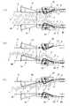
図5および図6は第2の実施例に係る容器の分岐装置の作動を示すもので、この実施例では、搬送コンベヤ8の両側に配置されている第1および第2揺動ガイド54、56を独立して揺動させるようになっている。上流側の2本の供給コンベヤ4、6からともに容器2が供給され、かつ、下流側の2本の排出コンベヤ10、12がともに満杯になっていない場合には、図5(a)に示すように、両側の第1,第2揺動ガイド54、56を搬送コンベヤ8の外側に揺動させて容器2に係合しないようにする。この場合には、両供給コンベヤ4、6からそれぞれ一列で搬送されてきた容器2は、両側に配置された振り分けガイド26、28の往復揺動により、搬送コンベヤ8上の全面に分散された状態のまま搬送される。従って、搬送される容器2に対して後方の容器2からプレッシャがかかることを防止することができる。また、各供給コンベヤ4、6からはほぼ同数の容器2が供給され、両側の振り分けガイド26、28に同じ揺動動作をさせることにより、搬送コンベヤ8上には、搬送方向の中央を境にしてほぼ同数の容器2が振り分けられて搬送される。 5 and 6 show the operation of the container branching apparatus according to the second embodiment. In this embodiment, the first and second swing guides 54 and 56 arranged on both sides of the
下流側の両排出コンベヤ10、12がいずれも満杯でなく容器2を搬送するとともに、上流側の2本の供給コンベヤ4、6の一方からの容器2の供給が停止した場合には、片側の供給コンベヤ4または6からだけ供給された容器2を、2本の排出コンベヤ10、12にほぼ均等に分散させる必要がある。例えば、第1供給コンベヤ4から容器2の供給が停止された場合には、図5(b)に示すように、この第1供給コンベヤ4と同じ側(搬送方向右側)の第1揺動ガイド54を搬送コンベヤ8上の容器2に係合しない位置まで後退させるとともに、容器2を正常に供給している第2供給コンベヤ6側の第2揺動ガイド56を、搬送コンベヤ8の中央方向へ揺動させて容器2に係合させ、搬送コンベヤ8の片側に寄せられて供給された容器2が、搬送コンベヤ8の中央部を搬送されるように搬送方向を変更する。 When both the
逆に、第2供給コンベヤ6から容器2の供給が停止された場合には、図5(c)に示すように、この第2供給コンベヤ6と同じ側(搬送方向左側)の第2揺動ガイド56を搬送コンベヤ8上の容器2に係合しない位置まで後退させるとともに、容器2を供給している第1供給コンベヤ4側の第1揺動ガイド54を、搬送コンベヤ8の中央方向へ揺動させて容器2に係合させ、搬送コンベヤ8の片側に寄せられて供給された容器2が、搬送コンベヤ8の中央部を搬送されるように搬送方向を変更する。 On the contrary, when the supply of the
図5は、下流側の2本の排出コンベヤ10、12がいずれも満杯でなく容器2を搬送している場合であったが、両排出コンベヤ10、12の一方が満杯となった場合の作動について、図6(a)〜(d)により説明する。図6(a)は、上流側の第1供給コンベヤ4から容器2の供給が停止され、第2供給コンベヤ6だけで容器2を供給するとともに、2本の排出コンベヤ10、12のうち、容器2の供給を停止している第1供給コンベヤ4と同じ側に配置されている第1排出コンベヤ10が満杯の場合である。この場合には、第2供給コンベヤ4から供給された容器2が、この第2供給コンベヤ6の側(搬送方向左側)を通ってそのまま第2排出コンベヤ12に送られるように、第2供給コンベヤ6および第2排出コンベヤ12と同じ側(搬送方向左側)の第2揺動ガイド56を後退させて容器2に係合しないようにする。なお、第1揺動ガイド54も容器2に係合しない位置に後退させておく。 FIG. 5 shows the case where the two
また、逆に第2供給コンベヤ6から容器2の供給が停止され、第1供給コンベヤ4からだけ容器2が供給されてくるとともに、容器2が供給されない第2供給コンベヤ6と同じ側の第2排出コンベヤ12が満杯の場合には、第1供給コンベヤ4から供給された容器2を、同じ側(搬送方向右側)の第1排出コンベヤ10にそのまま送り込む。従って、図6(b)に示すように、第1揺動ガイド56を容器2に係合しないように搬送コンベヤ8の側部側に後退させておく。また、第2揺動ガイド56も容器2に係合しない位置に後退させておく。 Conversely, the supply of the
2本の供給コンベヤ4、6の一方から容器2の供給が停止されるとともに、この停止している供給コンベヤ4または6と逆側の排出コンベヤ12または10が満杯になっている場合は、容器2を供給している供給コンベヤ4、6の配置されている側と逆側の排出コンベヤ12、10に容器2を送り込むように容器2の搬送方向を変更しなければならない。つまり、第1供給コンベヤ4から容器2の供給が停止され、第2排出コンベヤ12が満杯である場合には、図6(c)に示すように、容器2を供給している第2供給コンベヤ6側(搬送方向左側)の第2揺動ガイド56を、搬送コンベヤ8の内部側に大きく前進させるとともに、他方の第1揺動ガイド54を搬送コンベヤ8上の容器2に係合しないように搬送コンベヤ8の側部側まで後退させる。第2揺動ガイド56の長辺56bの下流端を、搬送コンベヤ8の搬送方向中央部よりも内部側まで揺動させることにより、搬送コンベヤ8上の容器2が中央部よりも右側を流れるように搬送方向を変更して、全ての容器2を搬送コンベヤ8の第1下流部8DAに載せ、第1排出コンベヤ10に送ることができる。 When the supply of the
逆に、第2供給コンベヤ6から容器2の供給が停止され、第1排出コンベヤ10が満杯となった場合には、図6(d)に示すように、容器2を供給している第1供給コンベヤ4側の第1揺動ガイド54を、搬送コンベヤ8の内部側に大きく前進させるとともに、他方の第2揺動ガイド56を搬送コンベヤ8上の容器2に係合しないように搬送コンベヤ8の側部側まで後退させる。第1揺動ガイド54によって、搬送コンベヤ8上の容器2が中央部よりも左側を流れるように搬送方向を変更することにより、全ての容器2を搬送コンベヤ8の第2下流部8DBに載せ、第2排出コンベヤ12に送ることができる。 Conversely, when the supply of the
このように本実施例に係る装置では、従来のようにコンベヤの走行速度を調整する等の複雑な制御が必要なく、簡単な構成で、搬送される容器2を均等に振り分けて2本の排出コンベヤ10、12に送り込み、または、満杯でなく正常に容器2を搬送している排出コンベヤ10、12にだけ送り込むことができる。しかも、2本の供給コンベヤ4、6の一方から容器2が供給されずに容器2の供給量が少なくなった場合でも、2本の排出コンベヤ10、12に均等に容器2を割り振ることができる。 As described above, the apparatus according to the present embodiment does not require complicated control such as adjusting the traveling speed of the conveyor as in the prior art, and with a simple configuration, the
2 容器
4 供給コンベヤ(第1供給コンベヤ)
6 供給コンベヤ(第2供給コンベヤ)
8 搬送コンベヤ
10 排出コンベヤ(第1排出コンベヤ)
12 排出コンベヤ(第2排出コンベヤ)
40 分岐ガイド
54 揺動ガイド(第1揺動ガイド)
56 揺動ガイド(第2揺動ガイド)
62 容器検出手段(第1容器検出センサー)
64 容器検出手段(第2容器検出センサー)
68 第1満杯検出手段(第1満杯検出センサー)
70 第2満杯検出手段(第1満杯検出センサー)2
6 Supply conveyor (second supply conveyor)
8
12 Discharge conveyor (second discharge conveyor)
40
56 Swing guide (second swing guide)
62 Container detection means (first container detection sensor)
64 Container detection means (second container detection sensor)
68 First full detection means (first full detection sensor)
70 Second full detection means (first full detection sensor)
Claims (3)
Translated fromJapanese前記2列の供給コンベヤから容器が供給されている時には、前記一対の揺動ガイドを容器に係合しない位置に後退させ、あるいは、両揺動ガイドを搬送コンベヤの内方へ前進させ、また、いずれか一方の供給コンベヤからの容器の供給が停止した場合には、容器を供給している供給コンベヤ側の揺動ガイドにより容器の搬送方向を変更して、前記分岐ガイドへ向けて搬送させることを特徴とする容器の分岐装置。A transport conveyor for transporting containers, a first supply conveyor and a second supply conveyor for supplying containers from both sides of the transport direction of the transport conveyor, and containers disposed on both sides of the transport conveyor and transported on the transport conveyor A pair of swing guides capable of changing the transport direction, control means for controlling the operation of the swing guides, a first discharge conveyor connected to the transport conveyor and transporting the containers downstream, and a second A discharge guide, a branch guide disposed between the first discharge conveyor and the second discharge conveyor and guiding the containers conveyed by the transfer conveyor to one of the discharge conveyors, the first supply conveyor and the second a first container detecting means and the second container detecting means for detecting a state of supply of containers to be supplied from the supplyconveyor, upstream of the swing guide Vignetting, anda swingable pair of sorting guide allocation to engage multiple rows in a container supplied from the first or the second feed conveyor,
When containers are being supplied from the two rows of supply conveyors, the pair of swing guides are retracted to a position where they do not engage with the containers, or both swing guides are advanced inward of the conveyor, When the supply of containers from one of the supply conveyors is stopped, the container conveyance direction is changed by the swinging guide on the supply conveyor side supplying the containers, and the containers are conveyed toward the branch guide. A container branching device.
前記両排出コンベヤがいずれも満杯でない時には、前記一対の揺動ガイドの動作位置によって、前記第1排出コンベヤおよび第2排出コンベヤにほぼ均等に容器を振り分け、いずれか一方の排出コンベヤが満杯の時には、前記揺動ガイドによって、満杯でない排出コンベヤに全ての容器を送ることを特徴とする容器の分岐装置。A transport conveyor for transporting containers, a first supply conveyor and a second supply conveyor for supplying containers from both sides of the transport direction of the transport conveyor, and containers disposed on both sides of the transport conveyor and transported on the transport conveyor A pair of swing guides capable of changing the transport direction, control means for controlling the operation of the swing guides, a first discharge conveyor connected to the transport conveyor and transporting the containers downstream, and a second A discharge conveyor, a branch guide that is disposed between the first discharge conveyor and the second discharge conveyor and guides the containers conveyed by the transfer conveyor to one of the discharge conveyors, and the first discharge conveyor is full. a first full detection means for detecting that became a second full detecting means for detecting that the second discharge conveyor isfull, the swing guide Provided upstream, anda swingable pair of sorting guide allocation to engage multiple rows in a container supplied from the first or the second feed conveyor,
When both of the discharge conveyors are not full, the containers are distributed almost evenly to the first discharge conveyor and the second discharge conveyor according to the operation position of the pair of swing guides, and when one of the discharge conveyors is full A container branching device for feeding all containers to a discharge conveyor which is not full by the swing guide.
前記2列の供給コンベヤから容器が供給されるとともに、前記両排出コンベヤがいずれも満杯でない時には、一対の揺動ガイドを容器に係合しない位置に後退させ、あるいは、両揺動ガイドを搬送コンベヤの内方へ前進させ、また、いずれか一方の供給コンベヤからの容器の供給が停止し、かつ、前記両排出コンベヤがいずれも満杯でない時には、容器を供給している供給コンベヤ側の揺動ガイドにより容器の搬送方向を変更して、前記分岐ガイドへ向けて搬送させ、
2列の供給コンベヤから容器が供給され、かつ、一方の排出コンベヤが満杯の時には、満杯の排出コンベヤ側の揺動ガイドによって、全ての容器を満杯でない排出コンベヤ側に送り、
一方の供給コンベヤから容器の供給が停止されるとともに、この供給コンベヤと同一側の排出コンベヤが満杯の時は、揺動ガイドを容器に係合しない位置に後退させ、
一方の供給コンベヤから容器の供給が停止されるとともに、この供給コンベヤと逆側の排出コンベヤが満杯の時は、容器を供給している供給コンベヤ側の揺動ガイドによって、全ての容器を逆側の排出コンベヤに送ることを特徴とする容器の分岐装置。A transport conveyor for transporting containers, a first supply conveyor and a second supply conveyor for supplying containers from both sides of the transport direction of the transport conveyor, and containers disposed on both sides of the transport conveyor and transported on the transport conveyor A pair of swing guides capable of changing the transport direction, control means for controlling the operation of the swing guides, a first discharge conveyor connected to the transport conveyor and transporting the containers downstream, and a second A discharge guide, a branch guide disposed between the first discharge conveyor and the second discharge conveyor and guiding the containers conveyed by the transfer conveyor to one of the discharge conveyors, the first supply conveyor and the second First container detection means and second container detection means for detecting the supply state of the containers supplied from the supply conveyor, and the first discharge conveyor are fully filled. A first full detecting means for detecting that became a second full detecting means for detecting that the second discharge conveyor isfull, disposed upstream of the swing guide, the first or second (2) A pair of swinging guides that engage with the containers supplied from the supply conveyor and can be distributed in multiple rows ,
When containers are supplied from the two rows of supply conveyors and both the discharge conveyors are not full, the pair of swing guides are retracted to a position where they do not engage with the containers, or both swing guides are moved to the transport conveyor. When the supply of containers from one of the supply conveyors stops and both the discharge conveyors are not full, the swing guide on the supply conveyor side supplying the containers Change the transport direction of the container with, and transport toward the branch guide,
When containers are supplied from two rows of supply conveyors and one of the discharge conveyors is full, all containers are sent to the non-full discharge conveyor side by the swing guide on the side of the full discharge conveyor,
When the supply of containers from one supply conveyor is stopped and the discharge conveyor on the same side as this supply conveyor is full, the swing guide is moved backward to a position where it does not engage with the containers,
When the supply of containers from one supply conveyor is stopped and the discharge conveyor on the opposite side of this supply conveyor is full, all the containers are placed on the reverse side by the swing guide on the supply conveyor side that supplies the containers. Container branching device characterized by being sent to a discharge conveyor of the container.
Priority Applications (1)
| Application Number | Priority Date | Filing Date | Title |
|---|---|---|---|
| JP2006059273AJP4725370B2 (en) | 2006-03-06 | 2006-03-06 | Container branching device |
Applications Claiming Priority (1)
| Application Number | Priority Date | Filing Date | Title |
|---|---|---|---|
| JP2006059273AJP4725370B2 (en) | 2006-03-06 | 2006-03-06 | Container branching device |
Publications (2)
| Publication Number | Publication Date |
|---|---|
| JP2007238200A JP2007238200A (en) | 2007-09-20 |
| JP4725370B2true JP4725370B2 (en) | 2011-07-13 |
Family
ID=38584108
Family Applications (1)
| Application Number | Title | Priority Date | Filing Date |
|---|---|---|---|
| JP2006059273AActiveJP4725370B2 (en) | 2006-03-06 | 2006-03-06 | Container branching device |
Country Status (1)
| Country | Link |
|---|---|
| JP (1) | JP4725370B2 (en) |
Families Citing this family (1)
| Publication number | Priority date | Publication date | Assignee | Title |
|---|---|---|---|---|
| US9205994B2 (en) | 2011-09-19 | 2015-12-08 | The Procter & Gamble Company | Methods for transferring items |
Family Cites Families (2)
| Publication number | Priority date | Publication date | Assignee | Title |
|---|---|---|---|---|
| JPH0891323A (en)* | 1994-09-26 | 1996-04-09 | Ishizu Seisakusho:Kk | Joining device for individual article |
| JP4220063B2 (en)* | 1999-04-22 | 2009-02-04 | 北海製罐株式会社 | Transport device |
- 2006
- 2006-03-06JPJP2006059273Apatent/JP4725370B2/enactiveActive
Also Published As
| Publication number | Publication date |
|---|---|
| JP2007238200A (en) | 2007-09-20 |
Similar Documents
| Publication | Publication Date | Title |
|---|---|---|
| US11787641B2 (en) | Method and device for distributing and/or grouping containers | |
| US8028815B2 (en) | Conveying device | |
| CN104271492B (en) | Filling device for containers and method of operating the same | |
| US10934103B2 (en) | Conveying storage device and method for operating the conveying storage device | |
| US6206174B1 (en) | Pressureless multi-lane dividing apparatus | |
| JP2008278888A (en) | Batch transport of rod-shaped articles for tobacco processing | |
| JP2011088741A (en) | Vessel carrying device | |
| JP2007269478A (en) | Shaking cell device and its control method | |
| JP4725370B2 (en) | Container branching device | |
| US8827065B2 (en) | Method and apparatus for transporting articles in a plurality of parallel buffer sections | |
| JP7576676B2 (en) | TRANSPORTATION APPARATUS AND TRANSPORTATION METHOD | |
| JP4639699B2 (en) | Container processing line | |
| JP5785693B2 (en) | Column increasing device | |
| JP4880558B2 (en) | Article supply device | |
| JP5448356B2 (en) | Accumulator conveyor method and apparatus | |
| JP4983037B2 (en) | Container branching device | |
| MXPA01007234A (en) | Low pressure dynamic accumulation table. | |
| JP2013199378A (en) | Article sorting facility | |
| JP5193387B1 (en) | Alignment transport device | |
| JP2010195534A (en) | Container conveying device | |
| US12297052B2 (en) | Transfer device for an apparatus for continuously conveying items, and method for continuously conveying items | |
| CN215324953U (en) | Device for conveying objects | |
| TW202110727A (en) | Branching equipment | |
| JP3991723B2 (en) | Container supply conveyor | |
| JP4207262B2 (en) | Container transfer device |
Legal Events
| Date | Code | Title | Description |
|---|---|---|---|
| A621 | Written request for application examination | Free format text:JAPANESE INTERMEDIATE CODE: A621 Effective date:20081127 | |
| A977 | Report on retrieval | Free format text:JAPANESE INTERMEDIATE CODE: A971007 Effective date:20101216 | |
| A131 | Notification of reasons for refusal | Free format text:JAPANESE INTERMEDIATE CODE: A131 Effective date:20101221 | |
| A521 | Request for written amendment filed | Free format text:JAPANESE INTERMEDIATE CODE: A523 Effective date:20110215 | |
| TRDD | Decision of grant or rejection written | ||
| A01 | Written decision to grant a patent or to grant a registration (utility model) | Free format text:JAPANESE INTERMEDIATE CODE: A01 Effective date:20110315 | |
| A61 | First payment of annual fees (during grant procedure) | Free format text:JAPANESE INTERMEDIATE CODE: A61 Effective date:20110328 | |
| R150 | Certificate of patent or registration of utility model | Ref document number:4725370 Country of ref document:JP Free format text:JAPANESE INTERMEDIATE CODE: R150 Free format text:JAPANESE INTERMEDIATE CODE: R150 | |
| FPAY | Renewal fee payment (event date is renewal date of database) | Free format text:PAYMENT UNTIL: 20140422 Year of fee payment:3 |