JP4724894B2 - Solid separation device - Google Patents
Solid separation deviceDownload PDFInfo
- Publication number
- JP4724894B2 JP4724894B2JP30693999AJP30693999AJP4724894B2JP 4724894 B2JP4724894 B2JP 4724894B2JP 30693999 AJP30693999 AJP 30693999AJP 30693999 AJP30693999 AJP 30693999AJP 4724894 B2JP4724894 B2JP 4724894B2
- Authority
- JP
- Japan
- Prior art keywords
- solid
- fluid
- cyclone
- swirl
- solid separation
- Prior art date
- Legal status (The legal status is an assumption and is not a legal conclusion. Google has not performed a legal analysis and makes no representation as to the accuracy of the status listed.)
- Expired - Fee Related
Links
- 239000007787solidSubstances0.000titleclaimsdescription141
- 238000000926separation methodMethods0.000titleclaimsdescription49
- 239000012530fluidSubstances0.000claimsdescription105
- 238000004062sedimentationMethods0.000claimsdescription25
- 230000001133accelerationEffects0.000claimsdescription22
- 239000011148porous materialSubstances0.000claimsdescription20
- 230000001174ascending effectEffects0.000claimsdescription2
- 239000007788liquidSubstances0.000description19
- 238000000034methodMethods0.000description17
- 239000010419fine particleSubstances0.000description10
- 238000000605extractionMethods0.000description7
- 230000002265preventionEffects0.000description7
- 238000005192partitionMethods0.000description5
- 230000000694effectsEffects0.000description4
- 230000005484gravityEffects0.000description4
- 239000002245particleSubstances0.000description4
- XLYOFNOQVPJJNP-UHFFFAOYSA-NwaterSubstancesOXLYOFNOQVPJJNP-UHFFFAOYSA-N0.000description3
- 230000001965increasing effectEffects0.000description2
- 239000000843powderSubstances0.000description2
- 238000001556precipitationMethods0.000description2
- 239000010802sludgeSubstances0.000description2
- 239000000126substanceSubstances0.000description2
- 238000011144upstream manufacturingMethods0.000description2
- 238000007664blowingMethods0.000description1
- 238000004140cleaningMethods0.000description1
- 230000006866deteriorationEffects0.000description1
- 238000010586diagramMethods0.000description1
- 239000000428dustSubstances0.000description1
- 230000002708enhancing effectEffects0.000description1
- 239000000295fuel oilSubstances0.000description1
- 238000001027hydrothermal synthesisMethods0.000description1
- 239000002440industrial wasteSubstances0.000description1
- 238000004519manufacturing processMethods0.000description1
- 239000002184metalSubstances0.000description1
- 239000000203mixtureSubstances0.000description1
- 230000002093peripheral effectEffects0.000description1
- 238000004080punchingMethods0.000description1
- 230000000630rising effectEffects0.000description1
Images


Landscapes
- Cyclones (AREA)
Description
Translated fromJapanese【0001】
【発明の属する技術分野】
本発明は、固体分離装置、より詳しくは、固液、及び固気の混合流体から固体を効率的に分離できるようにした固体分離装置に関するものである。
【0002】
【従来の技術】
近年、食品等の有機産業廃棄物、パルプスラッジ、粗悪重質油、汚泥、酒粕等のような液に固体が懸濁した混合流体中の有害な有機物を分解したり、或いはこうした混合流体を有価物に転用するために、超臨界水或いは臨界水による水熱反応装置を用いて処理することが行われているが、このような水熱反応装置で固液の混合流体を処理する場合には、混合流体中の固体(主に無機物)が水熱反応装置を含む処理設備のバルブ等に噛み込まれたり、或いは固体が処理設備の内部に付着・堆積して閉塞を起こすことにより、運転が困難になるという問題があり、このような問題の発生を未然に防止するために、固液の混合流体から固体を分離する固体分離装置が用いられている。
【0003】
一方、固体を粉砕して微粉を得る微粉製造設備、或いは粉塵等を分離してクリーンなガス(空気)を得るための設備等においては、固気の混合流体から固体を分離するための固体分離装置が用いられている。
【0004】
固液の混合流体から固体を分離する方法としては、主に沈降式と遠心式が従来から知られている。
【0005】
沈降式は、沈降槽に固液の混合流体を充填し、静置しておくことによって、固体と液体との比重差によって固体を沈降分離させる方法であり、又、遠心式は、例えばサイクロン式分離器のように固液の混合流体を旋回させて遠心力を与えることにより、液体と固体との比重差によって固体を分離する方法である。
【0006】
固気の混合流体から固体を分離する方法としては、主にフィルター式と、遠心式が従来から知られている。
【0007】
フィルター式は、固気の混合流体をフィルターに通してフィルターによって固体を捕捉する方法であり、又、遠心式は、例えばサイクロン式分離器のように固気の混合流体を旋回させて遠心力を与えることにより、気体と固体との比重差によって固体を分離する方法である。
【0008】
【発明が解決しようとする課題】
しかし、固液の混合流体から沈降式にて固体を分離する際において、混合流体の粘度が高く、しかも液体と固体との比重差が小さい場合には、固液の分離に非常に長時間を要し、能率的な分離ができないという問題があり、しかも大型の沈降槽とそれを設置するための広大なスペースが必要になる問題がある。
【0009】
又、固液の混合流体からサイクロン式分離器のような遠心式を用いて固体を分離する場合は、処理速度が大きく、混合流体の大量処理に適しているという利点がある反面、一般に遠心式で分離できる固体粒子の径は10ミクロン前後が限度であり、これより小さい数ミクロン〜サブミクロンのような微粒の固体を分離することはできなかった。特に、遠心式の分離では、ある程度微粒も一旦は捕集できるが、機構的に再飛散してしまうという問題があるために、分離性能を余り高めることができなかった。
【0010】
一方、固気の混合流体からフィルターを用いて固体を分離する場合は、フィルターの選定によって微粒の固体をも分離できる反面、フィルターが短時間で目詰まりを起こしてしまい、そのためにフィルターを逆洗によって機能回復させたり、或いはフィルターを新しいものと交換するといった作業が頻繁に必要であり、このために連続した分離作業ができないという問題がある。更に、フィルターが目詰まりを起こすと、圧損が大きくなって処理能力が低下し、このために安定した運転ができないという問題がある。
【0011】
又、固気の混合流体から遠心式にて固体を分離する場合は、処理速度が大きく、混合流体の大量処理に適している反面、前記固液の混合流体を分離する場合と同様に、一般に遠心式で分離できる固体粒子の径は10ミクロン前後が限度であり、これより小さい数ミクロン〜サブミクロンのような微粒の固体を分離することはできなかった。特に、遠心式の分離では、ある程度微粒も一旦は捕集できるが、機構的に再飛散してしまうという問題があるために、分離性能を余り高めることができなかった。
【0012】
上記したように、従来、固液、及び固気の混合流体から固体を分離する際に、数ミクロン或いはそれ以下の微粒をも、効率的にしかも安定して分離することはできなかった。
【0013】
本発明は、かかる従来技術のもつ問題点を解決すべくなしたもので、固液、及び固気の混合流体から微粒の固体をも高能率に分離することができ、しかも捕集した固体が再飛散するのを防止して確実な分離ができるようにした固体分離装置を提供することを目的としている。
【0014】
【課題を解決するための手段】
本発明は、上部に接線方向から接続された混合流体導入口を備え、下部に下方に向けて縮径する旋回加速部を備え、且つ軸中心上部に流体出口を備えたサイクロンと、
サイクロンの旋回加速部下端に接続されて鉛直下方に延びる多孔管と、
多孔管の外周を包囲して多孔管の細孔から遠心力により外方に排出される固体を受ける固体分離室を有し、該固体分離室の内部に流体の旋回を止めて固体を下方に移動させるための旋回止め部材を有する遠心分離器と、
多孔管の下端に接続され多孔管内部を下降する旋回流が軸中心を通る上昇流に反転するように下方に向けて拡径された旋回減速部を有し、且つ該旋回減速部の下側に、前記混合流体が上昇流に反転する際に混合流体中より分離した固体を受けるための沈殿部を有する沈降分離器と、
前記旋回減速部の外側における前記固体分離室の下部に形成した固体取出室と、
を備えたことを特徴とする固体分離装置、に係るものである。
【0015】
上記手段において、サイクロンの旋回加速部をテーパ多孔板により形成し、該テーパ多孔板の外周を包囲する固体分離室の内部に旋回止め部材を備えて加速部遠心分離器を構成してもよい。
【0017】
上記本発明は、次のように作用する。
【0018】
多孔管の外側に設けた遠心分離器と、混合流体の流動方向の反転を利用した沈降分離器との組み合わせにより、混合流体の固体を数ミクロン〜サブミクロンの微粒まで、安定して連続且つ高能率に分離することができる。
【0019】
サイクロンの旋回加速部を、下方に向けて縮径したテーパ多孔板により形成し、テーパ多孔板の外側に加速部遠心分離器を構成したことにより、旋回加速部において外側に移動した固体がテーパ多孔板の細孔を通って外側に弾き飛ばされるようになるので、旋回加速部での二次流れの影響を無くして分離性能を高められる。
【0020】
分離器内に旋回止め部材を設けて分離器内での流体の旋回を抑制するようにしたことにより、固体の落下分離作用を高められる。
【0021】
【発明の実施の形態】
以下、本発明の好適な実施の形態を図面に基づいて説明する。
【0022】
図1は本発明の固体分離装置の一例を示したものであり、図1では超臨界水・水熱反応装置のような高温・高圧の固液の混合流体から固体を連続分離する場合を示している。
【0023】
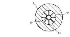
図1において、本体1の上部内側にサイクロン2を備えている。サイクロン2は、円筒状空間の上部に、図2のように接線方向から混合流体導入口3が接続されており、下部には下方に向けて縮径したテーパ状の旋回加速部4が形成されており、更に軸中心上部には流体出口2aが設けられている。
【0024】
サイクロン2の旋回加速部4の下端には、鉛直下方に延びる多孔管5が接続されている。多孔管5は、パンチングメタル等にて構成されていて多数の細孔6が形成されている。
【0025】
多孔管5は、細孔6を通して固体を外側に移動させるためのものであり、固体の移動を容易にするために、多孔管5は薄板で構成することが好ましく、又、細孔6の形状は種々選定することができるが、図3に示すように旋回流の旋回方向に長い長穴になっていると固体が外側に移動し易いので好ましい。
【0026】
多孔管5の外周には、多孔管5の細孔6から遠心力によって外方に排出される固体を回収するための遠心分離器7が設けられている。
【0027】
多孔管5の下端には、下方に向かって拡径されたテーパ状の旋回減速部8が接続されており、該旋回減速部8の下部には混合流体中より分離した固体を受ける沈殿部8aを備えた沈降分離器9が形成されている。
【0028】
遠心分離器7は、図1、図4に示すように、多孔管5の外周面を所要の空間を隔てて包囲する固体分離室10を備えており、該固体分離室10の内部には、多孔管5の細孔6から外側に排出される流体の旋回を止めて固体を下方に移動させるための旋回止め部材11を備えている。旋回止め部材11は、図4のように固体分離室10の内面に放射状に固定され、且つ多孔管5との間に所要の隙間を隔てた幅の複数の板で構成することができる。この旋回止め部材11は、図示の形状のものに限定されるものではなく、更に旋回止め部材11は固体を下方に向かわせるように捻られていてもよい。
【0029】
更に、多孔管5の下端における細孔6を有していない部分と固体分離室10の内面との間には、図5に示すように、放射状の再飛散防止板12が設けられており、該再飛散防止板12の下部における旋回減速部8の外側位置には、固体取出室13が形成されている。上記再飛散防止板12は、固体取出室13内の流体の変動を押えて安定させ得るものであれば、種々の形状のものを採用することができる。固体取出室13の底部には固体取出口14が備えられている。又、固体取出室13底部の所要位置には、分離された固体を固体取出口14に向かわせるための流体吹込口15が備えられている。
【0030】
図1に矢印で示すように、サイクロン2によって旋回された混合流体の旋回流は、多孔管5内を旋回しながら沈降分離器9の旋回減速部8の上端近傍まで下降した後、反転部16で反転して軸中心を上昇して流体出口2aに向かうようになっている。このように、旋回減速部8では旋回力が弱められ、しかも下降してきた混合流体が反転部16で反転して上昇することにより、流体と共に下降してきた微粒の固体が慣性と自重とによって効果的に沈殿部8a内下部に分離されるようになる。沈降分離器9の下部には、テーパ部17を介して固体取出口18が形成されている。
【0031】
又、サイクロン2の流体出口2aに連通した流体管19の途中には、清澄流体取出管20が接続されている。清澄流体取出管20の接続部より下流の流体管19には、混合流体供給管21が接続されており、混合流体は、水熱反応装置22によって処理された後、ポンプ23を介してサイクロン2の混合流体導入口3に導入されるようになっている。又、図1においては、ポンプ23出口の混合流体の一部が配管24、開閉弁25を介して前記流体吹込口15に導かれるようになっている。
【0032】
固体取出口14,18の夫々には開閉弁26が備えられている。更に、固体取出口14の開閉弁26の下流には、取出容器27を介して下流開閉弁28が備えられており、下流開閉弁28を閉じて開閉弁26を開け、開閉弁25を開けて混合流体の一部を流体吹込口15に供給することにより固体取出室13の固体を取出容器27に取り出し、その後開閉弁25,26を閉めて下流開閉弁28を開けることにより、取出容器27の固体を外部に排出できるようにしている。この方法によれば、本体1内部の圧力を保持した状態で、固体取出室13内に分離された固体を間欠的に取り出すことができる。一方、上記した取出容器27を備えることなく、固体取出口14に絞り等を設けることにより、本体1内の圧力を保持しつつ固体取出室13の固体を連続的に取り出すこともできる。
【0033】
又、上記では固体取出室13からの固体の取出しについて説明したが、沈降分離器9の固体取出口18にも、前記と同様に取出容器27を設けて固体を間欠的に取り出すようにしたり、或いは絞りを設けることにより固体を連続的に取り出すようにしてもよい。
【0034】
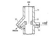
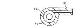
図6は、前記流体管19に対する清澄流体取出管20の接続部の構成を示している。図6の例では、流体管19の軸線に対して、流体の上流側(サイクロン2側)に、90゜より小さい角度αで傾斜させて清澄流体取出管20を接続している。これにより、流体管19内を矢印方向に流動する流体中の微粒は慣性で直進しようとするため、清澄流体取出管20には微粒の混入が極めて少ない清澄流体を取り出すことができる。このとき、図7、図8に示すように、流体管19に対する清澄流体取出管20の接続部の直上流位置にオリフィス29を設けるようにすると、オリフィス29によって流体の流速が高められ、微粒の慣性力が高められることにより、微粒が清澄流体取出管20側に流出するのが更に減少し、清澄流体のみを取り出すことができるようになる。図中30は、オリフィス29上に堆積した固体を旋回流にて除去するために、流体管19に接線方向から所定の流体を吹き込むようにしたオリフィス洗浄ノズルである。
【0035】
以下に、上記図1に示した形態例の作用を説明する。
【0036】
サイクロン2に対して接線方向に接続された混合流体導入口3から混合流体を導入すると、混合流体はサイクロン2の内部で矢印で示すように旋回流を形成する。更に、この旋回流は、サイクロン2下部のテーパ状に縮径された旋回加速部4によって旋回が加速され、多孔管5内部を旋回しながら下降し、沈降分離器9における旋回減速部8の上端近傍で旋回力が弱まり、反転部16位置にて下降流から上昇流に反転し、軸中心を上昇して、サイクロン2の流体出口2aから外部に排出される。
【0037】
上記したように、サイクロン2によって旋回され、更に旋回加速部4によって旋回が加速された混合流体の固体は、遠心力の作用によって外側に移動し、多孔管5の細孔6から、遠心分離器7の固体分離室10に流体の一部と共に弾き出されるようになる。この時、多孔管5の細孔6から固体分離室10に排出される流体は、接線方向に排出されることになるために固体分離室10内においても旋回しようとする。しかし、固体分離室10の内部には旋回止め部材11が設けられているので、固体分離室10では旋回が防止され、これによって固体は固体分離室内を下方に落下し、分離される。
【0038】
更に、遠心分離器7で分離された固体は再飛散防止板12を通って固体取出室13に落下し、固体取出口14から間欠的に、又は連続的に外部に取り出される。この時、固体取出室13の上部に設けた再飛散防止板12によって、固体取出室13内の流体は変動を押えられて安定するので、固体取出室13に落下した微粒は再飛散することなく沈下し、よって固体を確実に分離することができる。
【0039】
一方、上記遠心分離器7で分離されなかった固体を含む混合流体は、旋回減速部8の上部近傍で旋回力が弱められ、且つ下降してきた流体が反転部16で反転して上昇することにより、流体と共に下降してきた微粒の固体が慣性と自重とによって沈殿部8a内を下降するようになり、これにより沈降分離器9によって微粒の固体も分離されるようになる。沈降分離器9で分離された固体は、下部のテーパ部17を経て固体取出口18に落下し、固体取出口18から間欠的に、又は連続的に外部に取り出される。
【0040】
上記したように、多孔管5の外側に設けた遠心分離器7と、混合流体の流動方向の反転を利用した沈降分離器9との組み合わせにより、混合流体の固体を数ミクロン〜サブミクロンの微粒まで、安定して連続且つ高能率に分離することができる。
【0041】
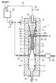
図9は本発明の他の形態例を示したものである。図9の構成では、サイクロン2の旋回加速部4を、細孔31aを有するテーパ多孔板31にて構成している。この場合の細孔31aも図3に示したような長穴としてもよい。
【0042】
更に、テーパ多孔板31の外周に、テーパ多孔板31を包囲し且つ仕切板32によって前記遠心分離器7の固体分離室10と仕切られた固体分離室33を形成し、更に固体分離室33の内部に図1の旋回止め部材11と同様の旋回止め部材34を備えた加速部遠心分離器35を構成している。加速部遠心分離器35の底部には、開閉弁26を備えた固体取出口36が設けられている。尚、上記した構成以外は、図1の構成と同様であるので、説明は省略する。
【0043】
図9の形態例によれば、サイクロン2の旋回加速部4における固体分離性を高めて、更に効果的な固体分離を行うことができる。
【0044】
即ち、サイクロン2の内部では、図1、図9に示したような旋回流が形成されると同時に、図10に示すように旋回加速部4の内面に沿って上下に循環する二次流れ37が生じる。この二次流れ37のために、遠心力で外側に移動した微粒が二次流れ37に巻き込まれて循環し、微粒の一部が軸中心を上昇する上昇流に乗って流体出口2aに流出してしまい、この問題がサイクロンを用いた場合に分離性能を大幅に高められない原因となっていた。
【0045】
しかし、図9の装置によれば、サイクロン2の旋回加速部4をテーパ多孔板31によって形成し、テーパ多孔板31の外側に加速部遠心分離器35を構成したので、旋回による遠心力によって外側に移動した固体は、図10の二次流れ37に乗って内側に戻ることなく、そのままテーパ多孔板31の細孔31aを通って外側に排出されるので、従来の二次流れ37によって分離性能が悪化するという問題を無くして高能率な固体分離を達成することができる。
【0046】
図11は、本発明の更に他の形態例を示している。図11中、図1及び図9と同じ符号を付した部分は同一のものを表わしており詳細な説明は省略する。
【0047】
本体1の内部に略円筒状の空間38が形成されており、空間38の上部にサイクロン2が構成されている。サイクロン2は、空間38の上部に接線方向から接続された混合流体導入口3を有しており、混合流体導入口3の下部位置には、下方に向けて縮径した細孔31aを有するテーパ多孔板31によって旋回加速部4が構成されており、且つ軸中心上部には流体出口2aが備えられている。
【0048】
旋回加速部4の下端外周部には、空間38の外周部を上下に仕切る仕切板39が設けられている。
【0049】
仕切板39上側の空間38内面には、図9と同様の旋回止め部材34が設けられており、更に、テーパ多孔板31の細孔31aから遠心力によって外方に排出される固体を受けるようにした加速部遠心分離器35が構成されている。
【0050】
仕切板39下側の空間38内面には、放射状の旋回止め部材41を備えることとにより沈降分離器42を構成している。
【0051】
図11の形態例によれば、サイクロン2によって旋回され、テーパ多孔板31による旋回加速部4にて加速された混合流体の旋回流は、矢印で示すように、沈降分離器42の上端近傍まで下降した後、反転部16で反転して軸中心を上昇して流体出口2aに向かう。
【0052】
この時、サイクロン2の旋回流による遠心力によって外側に移動した固体は、図10に示した二次流れ37に乗って内側に戻ることなく、そのままテーパ多孔板31の細孔31aを通って外側の加速部遠心分離器35に弾き出されるようになる。従って、従来のように二次流れ37によって分離性能が悪化する問題を無くすことができて、高能率な固体分離を達成することができる。加速部遠心分離器35に排出された固体は旋回止め部材41により旋回が押えられていることにより安定して下部に落下し、固体取出口36から間欠的に、又は連続的に外部に取り出される。
【0053】
一方、上記加速部遠心分離器35で分離されなかった固体を含む流体は、沈降分離器42の上端近傍で旋回力が弱められ、且つ下降してきた流体が反転部16で反転して上昇することにより、流体と共に下降してきた微粒の固体が慣性と自重とによって沈降分離器42内を下降するようになり、これによって沈降分離器42では微粒の固体も分離できるようになる。沈降分離器42で分離された固体は、下部のテーパ部17により固体取出口18に落下して、固体取出口18から間欠的に、又は連続的に外部に取り出される。
【0054】
尚、本発明は上記形態例にのみ限定されるものではなく、図示例では固液混合液体からの固体の分離について説明したが、固気混合流体からの固体の分離にも適用できること、固体を分離する混合流体の圧力は種々の圧力の場合でも実施できること、その他本発明の要旨を逸脱しない範囲内において種々変更を加え得ること、等は勿論である。
【0055】
【発明の効果】
本発明によれば、多孔管の外側に設けた遠心分離器と、混合流体の流動方向の反転を利用した沈降分離器との組み合わせにより、混合流体の固体を数ミクロン〜サブミクロンの微粒まで、安定して連続且つ高能率に分離することができる効果がある。
【0056】
サイクロンの旋回加速部を、下方に向けて縮径したテーパ多孔板により形成し、テーパ多孔板の外側に加速部遠心分離器を構成したことにより、旋回加速部において外側に移動した固体がテーパ多孔板の細孔を通って外側に弾き飛ばされるようになるので、旋回加速部での二次流れの影響を無くして分離性能を高められる効果がある。
【0057】
分離器内に旋回止め部材を設けて分離器内での流体の旋回を抑制するようにしたことにより、固体の落下分離作用を高められる効果がある。
【図面の簡単な説明】
【図1】本発明の固体分離装置の形態の一例を示す切断側面図である。
【図2】図1のII方向矢視図である。
【図3】多孔管の細孔の形状例を示す部分側面図である。
【図4】図1のIV方向矢視図である。
【図5】図1のV方向矢視図である。
【図6】流体管に対する清澄流体取出管の接続部の構成例を示す切断側面図である。
【図7】流体管に対する清澄流体取出管の接続部の他の構成例を示す切断側面図である。
【図8】図7のVIII方向矢視図である。
【図9】本発明の固体分離装置の他の形態例を示す切断側面図である。
【図10】サイクロンにおける二次流れを説明するための概略図である。
【図11】本発明の固体分離装置の更に他の形態例を示す切断側面図である。
【符号の説明】
2 サイクロン
2a 流体出口
3 混合流体導入口
4 旋回加速部
5 多孔管
6 細孔
7 遠心分離器
8 旋回減速部
8a 沈殿部
9 沈降分離器
10 固体分離室
11 旋回止め部材
12 再飛散防止板
13 固体取出室
16 反転部
31 テーパ多孔板
31a 細孔
33 固体分離室
34 旋回止め部材
35 加速部遠心分離器
38 空間
39 仕切板
41 旋回止め部材
42 沈降分離器[0001]
BACKGROUND OF THE INVENTION
The present invention relates to a solid separator, and more particularly, to a solid separator capable of efficiently separating a solid from a solid-liquid and solid-gas mixed fluid.
[0002]
[Prior art]
In recent years, harmful organic substances in mixed fluids in which solids are suspended in liquids such as organic industrial waste such as food, pulp sludge, crude heavy oil, sludge, and sake lees are decomposed, or such mixed fluids are valuable. In order to divert to a product, supercritical water or a hydrothermal reactor with critical water is used for processing, but when processing a solid-liquid mixed fluid with such a hydrothermal reactor, The solid fluid (mainly inorganic substance) in the mixed fluid is caught in the valve of the processing equipment including the hydrothermal reactor, or the solid adheres to and accumulates inside the processing equipment, causing the operation to be blocked. In order to prevent such a problem from occurring, a solid separation device that separates a solid from a solid-liquid mixed fluid is used.
[0003]
On the other hand, in a fine powder production facility that pulverizes a solid to obtain a fine powder, or a facility that separates dust and the like to obtain a clean gas (air), a solid separation for separating a solid from a solid-gas mixed fluid The device is used.
[0004]
As a method for separating a solid from a solid-liquid mixed fluid, a sedimentation method and a centrifugal method are conventionally known.
[0005]
The sedimentation method is a method in which a solid is mixed with a liquid mixture in a sedimentation tank and allowed to stand, whereby the solid is settled and separated by the specific gravity difference between the solid and the liquid. The centrifugal method is, for example, a cyclone method. This is a method of separating a solid by a specific gravity difference between a liquid and a solid by swirling a solid-liquid mixed fluid and applying a centrifugal force like a separator.
[0006]
As a method for separating a solid from a solid-gas mixed fluid, a filter type and a centrifugal type are conventionally known.
[0007]
The filter type is a method in which a solid-gas mixed fluid is passed through a filter and the solid is captured by the filter, and the centrifugal type is a method in which a solid-gas mixed fluid is swirled, for example, as in a cyclone separator to generate centrifugal force. In this method, the solid is separated by the difference in specific gravity between the gas and the solid.
[0008]
[Problems to be solved by the invention]
However, when solids are separated from solid-liquid mixed fluids by sedimentation, if the mixed fluid has a high viscosity and the specific gravity difference between the liquid and the solid is small, it takes a very long time to separate the solid and liquid. In other words, there is a problem that efficient separation is not possible, and there is a problem that a large sedimentation tank and a large space for installing it are required.
[0009]
In addition, when solids are separated from a solid-liquid mixed fluid using a centrifugal method such as a cyclonic separator, there is an advantage that the processing speed is high and it is suitable for mass processing of mixed fluids. The size of the solid particles that can be separated by the method is limited to around 10 microns, and it was not possible to separate fine solids such as several microns to submicrons smaller than this. In particular, in the centrifugal separation, although a certain amount of fine particles can be collected once, there is a problem in that they are re-scattered mechanically, so that the separation performance cannot be improved so much.
[0010]
On the other hand, when using a filter to separate solids from a solid-gas mixed fluid, fine solids can be separated by selecting the filter, but the filter clogs in a short time, and the filter is backwashed. Therefore, there is a problem in that it is frequently necessary to restore the function or to replace the filter with a new one, and therefore, continuous separation work cannot be performed. Further, when the filter is clogged, the pressure loss becomes large and the processing capacity is lowered, which causes a problem that stable operation cannot be performed.
[0011]
Also, when separating solids from solid-gas mixed fluids by centrifugal method, the processing speed is high and suitable for mass processing of mixed fluids, but in general, as with separating solid-liquid mixed fluids in general, The diameter of solid particles that can be separated by a centrifugal method is limited to around 10 microns, and fine solids such as several microns to submicrons smaller than this could not be separated. In particular, in the centrifugal separation, although a certain amount of fine particles can be collected once, there is a problem in that they are re-scattered mechanically, so that the separation performance cannot be improved so much.
[0012]
As described above, conventionally, when a solid is separated from a solid-liquid and solid-gas mixed fluid, it has been impossible to efficiently and stably separate fine particles of several microns or less.
[0013]
The present invention has been made to solve such problems of the prior art, and it is possible to efficiently separate fine solids from solid-liquid and solid-gas mixed fluids. It is an object of the present invention to provide a solid separation device that prevents re-scattering and enables reliable separation.
[0014]
[Means for Solving the Problems]
The present invention includes a cyclone having a mixed fluid introduction port connected to the upper part from the tangential direction, a swirl acceleration unit that reduces the diameter downward at the lower part, and a fluid outlet at the upper center of the shaft;
A perforated tube connected to the lower end of the turning acceleration portion of the cyclone and extending vertically downward;
Asolid separation chamber that surrounds the outer periphery ofthe perforated tube and receives solids discharged outward from the pores of the perforated tube by centrifugal force; A centrifugehaving a detent member for movement ;
A swirl reduction part connectedto the lower end ofthe perforated pipe and having adiameter expanded downward so that the swirling flow descending inside the perforated pipe is reversed to the ascending flow passing through the axial center, andbelow the swirl reduction part Anda sedimentation separatorhaving a sedimentation part for receiving solids separated from the mixed fluidwhen the mixed fluidis reversed into an upward flow ;
A solid take-out chamber formed in a lower portion of the solid separation chamber outside the swirl reduction unit;
The present invention relates to a solid separation device comprising:
[0015]
In the above means, a turning acceleration of the cyclone is formed by a tapered perforated plate,but it may also constitute the tapered perforated plate solid separation chamber of the accelerating portion centrifuge equipped with internal pivot stop member that surrounds the outer periphery of the .
[0017]
The present invention operates as follows.
[0018]
The combination of a centrifugal separator provided outside the perforated tube and a sedimentation separator that utilizes the reversal of the flow direction of the mixed fluid allows the solid of the mixed fluid to be continuously, continuously and high, from a few microns to sub-micron particles. It can be separated efficiently.
[0019]
The cyclone swirl acceleration part is formed by a tapered perforated plate with a diameter reduced downward, and an accelerator centrifuge is constructed outside the taper perforated plate. Since it is blown off through the pores of the plate, the influence of the secondary flow in the swirl acceleration portion can be eliminated and the separation performance can be improved.
[0020]
By providing a swirling stop member in the separator to suppress the swirling of the fluid in the separator, the action of separating and dropping the solid can be enhanced.
[0021]
DETAILED DESCRIPTION OF THE INVENTION
DESCRIPTION OF EXEMPLARY EMBODIMENTS Hereinafter, preferred embodiments of the invention will be described with reference to the drawings.
[0022]
FIG. 1 shows an example of a solid state separation apparatus according to the present invention. FIG. 1 shows a case where solids are continuously separated from a mixed liquid of high temperature and high pressure such as a supercritical water / hydrothermal reactor. ing.
[0023]
In FIG. 1, a
[0024]
A
[0025]
The
[0026]
On the outer periphery of the
[0027]
The lower end of the
[0028]
As shown in FIGS. 1 and 4, the
[0029]
Furthermore, a radial
[0030]
As indicated by arrows in FIG. 1, the swirling flow of the mixed fluid swirled by the
[0031]
A clarified fluid take-out
[0032]
Each of the
[0033]
In the above description, the extraction of the solid from the
[0034]
FIG. 6 shows the configuration of the connecting portion of the clarified fluid take-out
[0035]
Hereinafter, the operation of the embodiment shown in FIG. 1 will be described.
[0036]
When the mixed fluid is introduced from the mixed
[0037]
As described above, the solid of the mixed fluid swirled by the
[0038]
Further, the solid separated by the
[0039]
On the other hand, the mixed fluid containing the solid that has not been separated by the
[0040]
As described above, by combining the
[0041]
FIG. 9 shows another embodiment of the present invention. In the configuration of FIG. 9, the turning
[0042]
Further, on the outer periphery of the tapered
[0043]
According to the embodiment shown in FIG. 9, it is possible to improve solid separation in the turning
[0044]
That is, in the
[0045]
However, according to the apparatus of FIG. 9, the turning
[0046]
FIG. 11 shows still another embodiment of the present invention. In FIG. 11, the same reference numerals as those in FIGS. 1 and 9 represent the same parts, and detailed description thereof will be omitted.
[0047]
A substantially
[0048]
A
[0049]
9 is provided on the inner surface of the
[0050]
The inner surface of the
[0051]
11, the swirl flow of the mixed fluid swirled by the
[0052]
At this time, the solid moved to the outside by the centrifugal force due to the swirling flow of the
[0053]
On the other hand, the fluid containing solids not separated by the accelerating
[0054]
The present invention is not limited to the above-described embodiment. In the illustrated example, the solid separation from the solid-liquid mixed liquid has been described. However, the present invention can also be applied to the separation of the solid from the solid-gas mixed fluid. It goes without saying that the pressure of the mixed fluid to be separated can be implemented even at various pressures, and that various changes can be made without departing from the scope of the present invention.
[0055]
【The invention's effect】
According to the present invention, the combination of a centrifugal separator provided outside the perforated tube and a sedimentation separator that utilizes reversal of the flow direction of the mixed fluid allows the solids of the mixed fluid to be submicron to several micron to submicron particles, There exists an effect which can isolate | separate stably and continuously and highly efficiently.
[0056]
The cyclone swirl acceleration part is formed by a tapered perforated plate with a diameter reduced downward, and an accelerator centrifuge is constructed outside the taper perforated plate. Since it is blown out through the pores of the plate, there is an effect that the separation performance can be improved by eliminating the influence of the secondary flow in the turning acceleration portion.
[0057]
By providing a swirling stop member in the separator to suppress the swirling of the fluid in the separator, there is an effect of enhancing the falling and separating action of the solid.
[Brief description of the drawings]
FIG. 1 is a cut side view showing an example of a form of a solid separation device of the present invention.
FIG. 2 is a view taken in the direction of arrow II in FIG.
FIG. 3 is a partial side view showing a shape example of pores of a porous tube.
4 is a view taken in the direction of the arrow IV in FIG.
FIG. 5 is a view in the direction of the arrow V in FIG. 1;
FIG. 6 is a cut side view showing a configuration example of a connection portion of a clarified fluid take-out pipe with respect to a fluid pipe.
FIG. 7 is a cut-away side view showing another configuration example of the connection portion of the clarified fluid take-out pipe with respect to the fluid pipe.
8 is a view taken in the direction of arrow VIII in FIG.
FIG. 9 is a cut side view showing another embodiment of the solid separation device of the present invention.
FIG. 10 is a schematic diagram for explaining a secondary flow in a cyclone.
FIG. 11 is a cut side view showing still another embodiment of the solid separation device of the present invention.
[Explanation of symbols]
2
Claims (2)
Translated fromJapaneseサイクロンの旋回加速部下端に接続されて鉛直下方に延びる多孔管と、
多孔管の外周を包囲して多孔管の細孔から遠心力により外方に排出される固体を受ける固体分離室を有し、該固体分離室の内部に流体の旋回を止めて固体を下方に移動させるための旋回止め部材を有する遠心分離器と、
多孔管の下端に接続され多孔管内部を下降する旋回流が軸中心を通る上昇流に反転するように下方に向けて拡径された旋回減速部を有し、且つ該旋回減速部の下側に、前記混合流体が上昇流に反転する際に混合流体中より分離した固体を受けるための沈殿部を有する沈降分離器と、
前記旋回減速部の外側における前記固体分離室の下部に形成した固体取出室と、
を備えたことを特徴とする固体分離装置。A cyclone having a mixed fluid inlet connected to the upper part from the tangential direction, a swirl accelerating part having a diameter reduced downward at the lower part, and a fluid outlet at the upper part of the shaft center;
A perforated tube connected to the lower end of the turning acceleration portion of the cyclone and extending vertically downward;
Asolid separation chamber that surrounds the outer periphery ofthe perforated tube and receives solids discharged outward from the pores of the perforated tube by centrifugal force; A centrifugehaving a detent member for movement ;
A swirl reduction part connectedto the lower end ofthe perforated pipe and having adiameter expanded downward so that the swirling flow descending inside the perforated pipe is reversed to the ascending flow passing through the axial center, andbelow the swirl reduction part Anda sedimentation separatorhaving a sedimentation part for receiving solids separated from the mixed fluidwhen the mixed fluidis reversed into an upward flow ;
A solid take-out chamber formed in a lower portion of the solid separation chamber outside the swirl reduction unit;
A solid separation device comprising:
Priority Applications (1)
| Application Number | Priority Date | Filing Date | Title |
|---|---|---|---|
| JP30693999AJP4724894B2 (en) | 1999-10-28 | 1999-10-28 | Solid separation device |
Applications Claiming Priority (1)
| Application Number | Priority Date | Filing Date | Title |
|---|---|---|---|
| JP30693999AJP4724894B2 (en) | 1999-10-28 | 1999-10-28 | Solid separation device |
Publications (2)
| Publication Number | Publication Date |
|---|---|
| JP2001121038A JP2001121038A (en) | 2001-05-08 |
| JP4724894B2true JP4724894B2 (en) | 2011-07-13 |
Family
ID=17963107
Family Applications (1)
| Application Number | Title | Priority Date | Filing Date |
|---|---|---|---|
| JP30693999AExpired - Fee RelatedJP4724894B2 (en) | 1999-10-28 | 1999-10-28 | Solid separation device |
Country Status (1)
| Country | Link |
|---|---|
| JP (1) | JP4724894B2 (en) |
Families Citing this family (12)
| Publication number | Priority date | Publication date | Assignee | Title |
|---|---|---|---|---|
| US7402245B2 (en)* | 2005-01-21 | 2008-07-22 | Ebara Corporation | Digested sludge treatment apparatus |
| JP2007050354A (en)* | 2005-08-18 | 2007-03-01 | Sangyo Kiden Kk | Powder extraction apparatus |
| JP4743627B2 (en)* | 2006-06-30 | 2011-08-10 | 水ing株式会社 | Water or sludge treatment equipment containing ions in liquid |
| JP4878618B2 (en)* | 2008-11-05 | 2012-02-15 | 株式会社ホーライ | Separation device |
| JP5736142B2 (en)* | 2010-10-12 | 2015-06-17 | 株式会社カワタ | Fine powder removal device |
| JP6061719B2 (en)* | 2013-02-15 | 2017-01-18 | 株式会社ジェイテクト | Coolant system |
| JP2015146951A (en)* | 2014-02-07 | 2015-08-20 | 横河電子機器株式会社 | Cleaning machine |
| CN106111359B (en)* | 2016-06-29 | 2018-05-22 | 东北石油大学 | De-oiling desanding three-phase integratedization separator |
| WO2022230664A1 (en)* | 2021-04-28 | 2022-11-03 | パナソニックIpマネジメント株式会社 | Centrifugal separator and washing machine provided with centrifugal separator |
| CN113304607B (en)* | 2021-06-28 | 2023-05-16 | 重庆华峰化工有限公司 | Nitrous oxide decomposition device and process |
| KR102554706B1 (en)* | 2023-01-26 | 2023-07-12 | 한종산업개발 주식회사 | High Efficiency Cyclone Dust Collector |
| CN118831743A (en)* | 2024-09-20 | 2024-10-25 | 航天氢能新乡气体有限公司 | Forced drainage formula hydrocyclone separation equipment |
Family Cites Families (13)
| Publication number | Priority date | Publication date | Assignee | Title |
|---|---|---|---|---|
| JPS5015662Y2 (en)* | 1971-04-28 | 1975-05-15 | ||
| JPS5412183U (en)* | 1977-06-29 | 1979-01-26 | ||
| JPS5687136U (en)* | 1979-12-10 | 1981-07-13 | ||
| JPS5944553U (en)* | 1982-09-10 | 1984-03-24 | 小坂 原大 | Dry vacuum recovery equipment |
| US4527396A (en)* | 1983-09-23 | 1985-07-09 | Westinghouse Electric Corp. | Moisture separating device |
| JPS60115564U (en)* | 1984-01-13 | 1985-08-05 | 株式会社日立製作所 | Equipment for removing water and suspended solids from crude oil |
| JPS60148048U (en)* | 1984-03-12 | 1985-10-01 | 三菱重工業株式会社 | gas liquid separation tank |
| JPH0227852Y2 (en)* | 1985-08-05 | 1990-07-26 | ||
| JPS6443361A (en)* | 1987-08-07 | 1989-02-15 | Niigata Engineering Co Ltd | Separator |
| JPH01274858A (en)* | 1988-04-25 | 1989-11-02 | Tadahiro Yuki | Separation by cyclone |
| JPH05340650A (en)* | 1992-06-09 | 1993-12-21 | Daikin Ind Ltd | Centrifugal separation type oil separator |
| JPH09239294A (en)* | 1996-03-08 | 1997-09-16 | Masayuki Kawahara | Dust collector for incinerator |
| JPH10384A (en)* | 1996-04-19 | 1998-01-06 | Yoshio Mikazuki | Cyclone type dust collector |
- 1999
- 1999-10-28JPJP30693999Apatent/JP4724894B2/ennot_activeExpired - Fee Related
Also Published As
| Publication number | Publication date |
|---|---|
| JP2001121038A (en) | 2001-05-08 |
Similar Documents
| Publication | Publication Date | Title |
|---|---|---|
| JP4359975B2 (en) | Solid separation device | |
| US5370600A (en) | Apparatus for separating lighter and heavier components of a mixture employing a removable liner | |
| US5407584A (en) | Water clarification method | |
| US5882530A (en) | Crossflow filter cyclone apparatus | |
| US3443696A (en) | Solid-fluid separating device | |
| EP2416886B1 (en) | Gas-liquid-solid separator | |
| EP2474364B1 (en) | Fluid separation hydrocyclone | |
| JP4724894B2 (en) | Solid separation device | |
| US4756729A (en) | Apparatus for separating dust from gases | |
| US4842145A (en) | Arrangement of multiple fluid cyclones | |
| JP2882880B2 (en) | Apparatus and method for centrally feeding a tank such as a round coarse trap, a round coarse classifier or a sedimentation tank, and a method of using the same | |
| US20060162299A1 (en) | Separation apparatus | |
| US5188238A (en) | Separator for separating solids components of liquid mixtures and method of using the same | |
| GB2332632A (en) | Separator | |
| JP4406976B2 (en) | Solid separation device | |
| WO2002085525A1 (en) | Centrifuge | |
| JP4085501B2 (en) | Solid-liquid separator | |
| EP0606716B1 (en) | Method and apparatus for separating phases | |
| CN102872668A (en) | Agglomerate cyclone separator | |
| CA2019390C (en) | Separator | |
| US5811006A (en) | Centrifugal separator with improved quiescent collection chamber | |
| WO1982002344A1 (en) | Fluid recovery system | |
| CA2230834C (en) | Concentrator for solids in a liquid medium | |
| NO345472B1 (en) | Water and hydrocarbon separator | |
| JPH04141251A (en) | Method and device for centrifugal separation |
Legal Events
| Date | Code | Title | Description |
|---|---|---|---|
| A621 | Written request for application examination | Free format text:JAPANESE INTERMEDIATE CODE: A621 Effective date:20060925 | |
| A131 | Notification of reasons for refusal | Free format text:JAPANESE INTERMEDIATE CODE: A131 Effective date:20090728 | |
| A521 | Written amendment | Free format text:JAPANESE INTERMEDIATE CODE: A523 Effective date:20090924 | |
| A521 | Written amendment | Free format text:JAPANESE INTERMEDIATE CODE: A523 Effective date:20100510 | |
| A01 | Written decision to grant a patent or to grant a registration (utility model) | Free format text:JAPANESE INTERMEDIATE CODE: A01 Effective date:20110315 | |
| A61 | First payment of annual fees (during grant procedure) | Free format text:JAPANESE INTERMEDIATE CODE: A61 Effective date:20110328 | |
| FPAY | Renewal fee payment (event date is renewal date of database) | Free format text:PAYMENT UNTIL: 20140422 Year of fee payment:3 | |
| LAPS | Cancellation because of no payment of annual fees |