JP4724711B2 - Robotized apparatus and method without using images to guide surgical tools - Google Patents
Robotized apparatus and method without using images to guide surgical toolsDownload PDFInfo
- Publication number
- JP4724711B2 JP4724711B2JP2007515953AJP2007515953AJP4724711B2JP 4724711 B2JP4724711 B2JP 4724711B2JP 2007515953 AJP2007515953 AJP 2007515953AJP 2007515953 AJP2007515953 AJP 2007515953AJP 4724711 B2JP4724711 B2JP 4724711B2
- Authority
- JP
- Japan
- Prior art keywords
- tool
- robot arm
- guide
- foot
- surgical
- Prior art date
- Legal status (The legal status is an assumption and is not a legal conclusion. Google has not performed a legal analysis and makes no representation as to the accuracy of the status listed.)
- Expired - Lifetime
Links
Images


Classifications
- A—HUMAN NECESSITIES
- A61—MEDICAL OR VETERINARY SCIENCE; HYGIENE
- A61B—DIAGNOSIS; SURGERY; IDENTIFICATION
- A61B17/00—Surgical instruments, devices or methods
- A61B17/14—Surgical saws
- A61B17/15—Guides therefor
- A61B17/154—Guides therefor for preparing bone for knee prosthesis
- A—HUMAN NECESSITIES
- A61—MEDICAL OR VETERINARY SCIENCE; HYGIENE
- A61B—DIAGNOSIS; SURGERY; IDENTIFICATION
- A61B17/00—Surgical instruments, devices or methods
- A61B17/56—Surgical instruments or methods for treatment of bones or joints; Devices specially adapted therefor
- A61B17/58—Surgical instruments or methods for treatment of bones or joints; Devices specially adapted therefor for osteosynthesis, e.g. bone plates, screws or setting implements
- A61B17/60—Surgical instruments or methods for treatment of bones or joints; Devices specially adapted therefor for osteosynthesis, e.g. bone plates, screws or setting implements for external osteosynthesis, e.g. distractors, contractors
- A61B17/64—Devices extending alongside the bones to be positioned
- A61B17/6408—Devices not permitting mobility, e.g. fixed to bed, with or without means for traction or reduction
- A—HUMAN NECESSITIES
- A61—MEDICAL OR VETERINARY SCIENCE; HYGIENE
- A61B—DIAGNOSIS; SURGERY; IDENTIFICATION
- A61B34/00—Computer-aided surgery; Manipulators or robots specially adapted for use in surgery
- A61B34/20—Surgical navigation systems; Devices for tracking or guiding surgical instruments, e.g. for frameless stereotaxis
- A—HUMAN NECESSITIES
- A61—MEDICAL OR VETERINARY SCIENCE; HYGIENE
- A61B—DIAGNOSIS; SURGERY; IDENTIFICATION
- A61B34/00—Computer-aided surgery; Manipulators or robots specially adapted for use in surgery
- A61B34/70—Manipulators specially adapted for use in surgery
- A—HUMAN NECESSITIES
- A61—MEDICAL OR VETERINARY SCIENCE; HYGIENE
- A61B—DIAGNOSIS; SURGERY; IDENTIFICATION
- A61B34/00—Computer-aided surgery; Manipulators or robots specially adapted for use in surgery
- A61B34/70—Manipulators specially adapted for use in surgery
- A61B34/76—Manipulators having means for providing feel, e.g. force or tactile feedback
- A—HUMAN NECESSITIES
- A61—MEDICAL OR VETERINARY SCIENCE; HYGIENE
- A61B—DIAGNOSIS; SURGERY; IDENTIFICATION
- A61B17/00—Surgical instruments, devices or methods
- A61B2017/00017—Electrical control of surgical instruments
- A61B2017/00022—Sensing or detecting at the treatment site
- A—HUMAN NECESSITIES
- A61—MEDICAL OR VETERINARY SCIENCE; HYGIENE
- A61B—DIAGNOSIS; SURGERY; IDENTIFICATION
- A61B34/00—Computer-aided surgery; Manipulators or robots specially adapted for use in surgery
- A61B34/10—Computer-aided planning, simulation or modelling of surgical operations
- A61B2034/108—Computer aided selection or customisation of medical implants or cutting guides
- A—HUMAN NECESSITIES
- A61—MEDICAL OR VETERINARY SCIENCE; HYGIENE
- A61B—DIAGNOSIS; SURGERY; IDENTIFICATION
- A61B34/00—Computer-aided surgery; Manipulators or robots specially adapted for use in surgery
- A61B34/20—Surgical navigation systems; Devices for tracking or guiding surgical instruments, e.g. for frameless stereotaxis
- A61B2034/2068—Surgical navigation systems; Devices for tracking or guiding surgical instruments, e.g. for frameless stereotaxis using pointers, e.g. pointers having reference marks for determining coordinates of body points
- A—HUMAN NECESSITIES
- A61—MEDICAL OR VETERINARY SCIENCE; HYGIENE
- A61B—DIAGNOSIS; SURGERY; IDENTIFICATION
- A61B34/00—Computer-aided surgery; Manipulators or robots specially adapted for use in surgery
- A61B34/25—User interfaces for surgical systems
- A61B2034/252—User interfaces for surgical systems indicating steps of a surgical procedure
- A—HUMAN NECESSITIES
- A61—MEDICAL OR VETERINARY SCIENCE; HYGIENE
- A61B—DIAGNOSIS; SURGERY; IDENTIFICATION
- A61B34/00—Computer-aided surgery; Manipulators or robots specially adapted for use in surgery
- A61B34/25—User interfaces for surgical systems
- A61B2034/254—User interfaces for surgical systems being adapted depending on the stage of the surgical procedure
- A—HUMAN NECESSITIES
- A61—MEDICAL OR VETERINARY SCIENCE; HYGIENE
- A61B—DIAGNOSIS; SURGERY; IDENTIFICATION
- A61B90/00—Instruments, implements or accessories specially adapted for surgery or diagnosis and not covered by any of the groups A61B1/00 - A61B50/00, e.g. for luxation treatment or for protecting wound edges
- A61B90/06—Measuring instruments not otherwise provided for
- A61B2090/064—Measuring instruments not otherwise provided for for measuring force, pressure or mechanical tension
- A61B2090/065—Measuring instruments not otherwise provided for for measuring force, pressure or mechanical tension for measuring contact or contact pressure
- A—HUMAN NECESSITIES
- A61—MEDICAL OR VETERINARY SCIENCE; HYGIENE
- A61B—DIAGNOSIS; SURGERY; IDENTIFICATION
- A61B90/00—Instruments, implements or accessories specially adapted for surgery or diagnosis and not covered by any of the groups A61B1/00 - A61B50/00, e.g. for luxation treatment or for protecting wound edges
- A61B90/08—Accessories or related features not otherwise provided for
- A61B2090/0801—Prevention of accidental cutting or pricking
- A61B2090/08021—Prevention of accidental cutting or pricking of the patient or his organs
- A—HUMAN NECESSITIES
- A61—MEDICAL OR VETERINARY SCIENCE; HYGIENE
- A61B—DIAGNOSIS; SURGERY; IDENTIFICATION
- A61B90/00—Instruments, implements or accessories specially adapted for surgery or diagnosis and not covered by any of the groups A61B1/00 - A61B50/00, e.g. for luxation treatment or for protecting wound edges
- A61B90/36—Image-producing devices or illumination devices not otherwise provided for
- A61B2090/363—Use of fiducial points
- A—HUMAN NECESSITIES
- A61—MEDICAL OR VETERINARY SCIENCE; HYGIENE
- A61B—DIAGNOSIS; SURGERY; IDENTIFICATION
- A61B34/00—Computer-aided surgery; Manipulators or robots specially adapted for use in surgery
- A61B34/25—User interfaces for surgical systems
- A—HUMAN NECESSITIES
- A61—MEDICAL OR VETERINARY SCIENCE; HYGIENE
- A61B—DIAGNOSIS; SURGERY; IDENTIFICATION
- A61B34/00—Computer-aided surgery; Manipulators or robots specially adapted for use in surgery
- A61B34/30—Surgical robots
- A—HUMAN NECESSITIES
- A61—MEDICAL OR VETERINARY SCIENCE; HYGIENE
- A61B—DIAGNOSIS; SURGERY; IDENTIFICATION
- A61B90/00—Instruments, implements or accessories specially adapted for surgery or diagnosis and not covered by any of the groups A61B1/00 - A61B50/00, e.g. for luxation treatment or for protecting wound edges
- A61B90/10—Instruments, implements or accessories specially adapted for surgery or diagnosis and not covered by any of the groups A61B1/00 - A61B50/00, e.g. for luxation treatment or for protecting wound edges for stereotaxic surgery, e.g. frame-based stereotaxis
- A61B90/14—Fixators for body parts, e.g. skull clamps; Constructional details of fixators, e.g. pins
Landscapes
- Health & Medical Sciences (AREA)
- Surgery (AREA)
- Life Sciences & Earth Sciences (AREA)
- Engineering & Computer Science (AREA)
- Animal Behavior & Ethology (AREA)
- Veterinary Medicine (AREA)
- Biomedical Technology (AREA)
- Heart & Thoracic Surgery (AREA)
- Medical Informatics (AREA)
- Molecular Biology (AREA)
- Nuclear Medicine, Radiotherapy & Molecular Imaging (AREA)
- General Health & Medical Sciences (AREA)
- Public Health (AREA)
- Robotics (AREA)
- Orthopedic Medicine & Surgery (AREA)
- Physical Education & Sports Medicine (AREA)
- Transplantation (AREA)
- Dentistry (AREA)
- Oral & Maxillofacial Surgery (AREA)
- Surgical Instruments (AREA)
- Manipulator (AREA)
- Prostheses (AREA)
Description
Translated fromJapanese本発明は、ロボット補助による外科手術システム及び方法の分野に関する。特に、本発明は、様々な外科手術的な応用における振動鋸刃もしくはドリルの機械的誘導に適用される。例えば、膝全置換手術において、本発明は、移植組織の取り付け精度及びその寿命を改善することによって信頼できる誘導システムを提供する。 The present invention relates to the field of robot-assisted surgical systems and methods. In particular, the present invention applies to the mechanical guidance of oscillating saw blades or drills in various surgical applications. For example, in total knee replacement surgery, the present invention provides a reliable guidance system by improving the accuracy of the graft attachment and its life.
多様な専門分野(整形外科、神経外科、口腔外科、その他)における多くの外科手術の手順・処置は、正確な骨の切断と穴開けを必要とする。正確な骨の切断と穴開けを必要とする場合は、例えば、脊柱手術(ペディキュラースクリュープレイスメント(pedicular screw placement))または神経外科における膝回りの外科手術(膝関節形成、脛骨もしくは大腿骨の骨きり術及び、靱帯修復)の場合である。 Many surgical procedures and procedures in a variety of specialized fields (orthopedics, neurosurgery, oral surgery, etc.) require precise bone cutting and drilling. If precise bone cutting and drilling is required, for example, spinal surgery (pedicular screw placement) or neurosurgical knee surgery (knee arthroplasty, tibial or femoral This is the case of osteotomy and ligament repair.
これらの手順・処置は、直接外科医もしくは基本的な機械的ガイドのどちらかにより位置決めと維持がなされる電動器具(外科用ドリル、振動鋸など)を使用して従来から実行されてきた。 These procedures / procedures have traditionally been performed using power tools (surgical drills, oscillating saws, etc.) that are positioned and maintained by either the direct surgeon or a basic mechanical guide.
しかし、既存の技術が良好でかつ予知できる結果を保証しないことを示す多くの研究文献がある。それらは、切断及び穴開けをより正確に行うことがより良い手術後の結果につながることを示唆している。 However, there is a lot of research literature showing that existing technologies do not guarantee good and predictable results. They suggest that more accurate cutting and drilling can lead to better post-operative results.
外科医の手術計画に完全に適合する外科手術の動きに関する改良されたシステム及び方法を提供することが望ましい。このような外科手術の動きの極めて大きな問題は、患者の体に対する切断もしくは穴開けの完全な位置決めとともに、切断もしくは穴開けの相対的な位置決めを行う必要があることである。 It would be desirable to provide an improved system and method for surgical movement that perfectly fits the surgeon's surgical plan. A very significant problem with such surgical movement is that it requires the relative positioning of the cut or punch as well as the complete positioning of the cut or punch relative to the patient's body.
人工膝関節置換術(Total knee replacement: TKR)は、正確な切断を必要とする外科手術の手順・処置の一例である。TKRでは、外科医が体の中心から見て遠い方の大腿骨と体の中心から見て近い方の脛骨を切除し、膝の機能性を正しく元に戻すためにそれらを補綴部品と取り替える。論題(これら)の部品(theses component)は、骨の物理的な軸に対して適切に配置(アライメント)されていなければならない。もしそうでなければ、膝の運動性が乏しくなるかまたは部品がゆるむこととなる。3本の軸(内反/外反、屈曲/伸展、内部/外部)に沿った方向及び、3本の軸(中央/側面、近い方/遠い方、前/後ろ)に沿った並進において、不整合(ミスアライメント)は、多くの異なる方法で起こり得る。現在、従来のTKRは、切断ブロック及び整列ロッドの複雑なジグシステムを用いている。外科医が、整列ロッドを予定された軸に沿った状態で切断ブロックを正しく配置することは難しい。 Total knee replacement (TCR) is an example of a surgical procedure / procedure that requires accurate cutting. In TKR, the surgeon resects the femur far from the center of the body and the tibia closer from the center of the body and replaces them with prosthetic parts to properly restore knee functionality. The topics (these) components must be properly aligned with the physical axis of the bone. If this is not the case, the mobility of the knee will be poor or the parts will loosen. In translation along three axes (inner / valgus, flexion / extension, internal / external) and translation along three axes (center / side, near / far, front / back) Misalignment can occur in many different ways. Currently, conventional TKR uses a complex jig system of cutting blocks and alignment rods. It is difficult for the surgeon to correctly position the cutting block with the alignment rod along the intended axis.
論題(これら)の技術が満足するものではないという証拠が文献に存在する。 “人工膝関節全置換手術におけるナビゲーション:従来技術と比較したCTに基づく移植(Navigation in total-knee arthroplasty : CT-based implantation compared with the conventional technique.)”、Perlick L、その他、Acta Orthop Scand 2004、第4巻、pp 464-470、“人工膝関節全置換手術後の大きな犠牲をはらう673例のPFC部品配置に関する外科医の経験の結果(The effect of surgeon experience on component positioning in 673 PFC posterior cruciate-sacrificing total knee arthroplasties)”、Mahaluxmivala J、その他、J. Arthroplasty 2001、第5巻、pp 635-640、などの研究によれば、このような手術のほとんど3分の1は、調整の限度(理想的な手術後の足の軸からの3度内反側から3度外反側の間)を越えている。Perlick L.、その他による“人工膝関節全置換手術中の足のアライメント再構築における、画像に基づいたナビゲーションシステムの有用性(Usability of an image based navigation system in reconstruction of leg alignment in total knee arthroplasty)”、Biomed Tech、ベルリン、2003、第12巻、pp 339-343において、50例の膝に関する研究では、そのうち70パーセントだけが調整限度内であったことを発見した。従来の方法は、足の軸と移植組織の間で正しい調整を達成する際に外科医を補助するが、その結果は外科医の経験に大きく依存している。 There is evidence in the literature that the topic (these) techniques are not satisfactory. “Navigation in total-knee arthroplasty: CT-based implantation compared with the conventional technique”, Perlick L, et al., Acta Orthop Scand 2004, Volume 4, pp 464-470, “The effect of surgeon experience on component positioning in 673 PFC posterior cruciate-sacrificing. total knee arthroplasties) ”, Mahaluxmivala J, et al., J. Arthroplasty 2001, Vol. 5, pp 635-640, etc. According to studies such as almost one third of such operations, the limit of adjustment (ideal 3 degrees from the axis of the foot after surgery and between 3 degrees valgus to 3 degrees valgus). Perlick L., et al. “Usability of an image based navigation system in reconstruction of leg alignment in total knee arthroplasty” Biomed Tech, Berlin, 2003, Volume 12, pp 339-343, a study of 50 knees found that only 70 percent were within adjustment limits. Conventional methods assist the surgeon in achieving the correct alignment between the foot axis and the implant, but the results are highly dependent on the surgeon's experience.
TKRの間、外科医を補助するためのいくつかの異なる方法が提案されてきた。ナビゲーションシステムは、追跡装置の空間位置の位置を見つける追跡システムに基づいている。追跡装置は、大腿骨、脛骨、切断ブロック及び、指示ツールのような機械的な装置に固定されている。外科医は、骨に対してツールの相対位置を視覚的に追うことができる。最初に、外科医は解剖学上の目印及び表面を追跡ポインターに登録して、運動学的な手順・処置によって股関節の中心を定義する。その後、ナビゲーションシステムは、異なる切断に対する骨の物理的な軸及び最適位置を計算することが可能である。外科医はピンをしっかりはめんだ後にナビゲーションシステムにより提供される視覚補助を用いて、切断ブロックを骨に取り付ける。このようなシステムの欠点は、それらの複雑さであり、長い作業時間が必要であり、実際の外科手術の動きの実現のための補助が足りないことである。外科医が固定ピンを埋め込むために、ナビゲーションシステムスクリーンから目を離すまさしくその瞬間に、切断ブロックの位置決め精度を大きく損なうこともあり得る。したがって、これらのナビゲーションシステムを使った方法は、依然として主に外科医の技術の依存している。 Several different methods have been proposed to assist surgeons during the TKR. The navigation system is based on a tracking system that locates the spatial position of the tracking device. The tracking device is fixed to mechanical devices such as the femur, tibia, cutting block and pointing tool. The surgeon can visually follow the relative position of the tool with respect to the bone. First, the surgeon registers anatomical landmarks and surfaces with the tracking pointer and defines the center of the hip joint by kinematic procedures. The navigation system can then calculate the physical axis and optimal position of the bone for different cuts. The surgeon attaches the cutting block to the bone using the visual aid provided by the navigation system after the pin has been secured. The disadvantages of such systems are their complexity, long working time, and lack of assistance to realize the actual surgical movement. The exact positioning of the cutting block can be severely compromised at the very moment when the surgeon takes his eye off the navigation system screen to implant the fixation pin. Therefore, the methods using these navigation systems remain largely dependent on the surgeon's skill.
自動化された(ロボティック)システムは、また、膝置換手術の間の骨切除を改善するために提案された。T. C. Kienzleは、“膝全置換(Total Knee Replacement)”IEEE Engineering in Medicine and Biology、第14巻、3号、1995-05-01において、調整されたロボットを使用するコンピューター補助の外科手術システムについて記述している。このシステムは、足のCTスキャンから得られた患者の骨の3次元モデルを表示するワークステーションと、補綴部品の配置を教示する修正された産業用ロボットを使用する。骨に取り付けられる基準マーカーの位置は、ロボット搭載フランジに取り付けられているプローブにより計測される。基準マーカーは、患者(ロボット参照フレーム)の位置に対する外科手術前の画像データ(CTスキャンフレーム)を登録することに役立つ。補綴部品の最適配置を計算した後に、ロボットは切断ブロックのための穴が配置されるところにドリルガイドを配置する。このシステムの主な欠点は、足のCTスキャンを行う前に、外科医が患者の大腿骨及び脛骨に侵襲ピン(invasive pin)を埋め込む外科手術準備手順・処置を行わなければならないことである。 An automated (robotic) system has also been proposed to improve bone resection during knee replacement surgery. TC Kienzle describes a computer-assisted surgical system using a coordinated robot in “Total Knee Replacement” IEEE Engineering in Medicine and Biology, Vol. 14, No. 3, 1995-05-01 is doing. The system uses a workstation that displays a 3D model of the patient's bone obtained from a CT scan of the foot and a modified industrial robot that teaches the placement of prosthetic components. The position of the reference marker attached to the bone is measured by a probe attached to the robot mounting flange. The fiducial marker helps register pre-surgical image data (CT scan frame) for the patient (robot reference frame) position. After calculating the optimal placement of the prosthetic component, the robot places the drill guide where the hole for the cutting block is placed. The main drawback of this system is that the surgeon must perform a surgical preparation procedure to implant invasive pins into the patient's femur and tibia before performing a CT scan of the foot.
他の自動化された装置が、米国特許第5,403,319号に開示されている。この装置は、骨を固定する装置、産業用ロボット及びロボットが搭載されるフランジに取り付けられたテンプレートから成る。このテンプレートは、膝の補綴物の大腿骨部品の外面に対応する機能性のある内面を有する。第1の段階で、外科医はテンプレートを補綴物の所望の位置に置き、ロボットはその位置を登録する。第2の段階で、このシステムは各切断作業のための座標データを生成するために登録した位置を幾何学データベースと組み合わせる。その後、ロボットはツールガイドを位置決めして、各特定の作業のために完全調整(整列)させる。実際の外科手術作業は、ツールガイドによって外科医により実行される。このシステムの主な欠点の1つは、その精度が「外科医が、視覚的に補綴物を空間上の最適位置に決定する能力がある」というありそうもない仮説に依存するということである。実際的には、手術後の良い結果を得るのに十分な精度で補綴物テンプレートをフリーハンドで所定の位置に置くことは、熟練度した外科医にとってさえほとんど不可能である。著者は、切断ガイドマークの様ないくつかの初歩的な調整手段、例えば、切断ガイドマーク、アライメントタブ及びリファレンスロッドなどについて記述しており、それらが骨に対する補綴物の位置及び方向を評価するために使用できるかもしれないことを記述している。これらの手段は、従来の計測より正確性で劣る。したがって、このシステムは、確かに従来のジグシステムより正確ではない。他の主な欠点は、このシステムが移植組織部品のタイプ及びサイズ各々に対して1つの補綴テンプレートを必要とすることである。商業化されている補綴物には約100の異なるモデルがあり、かつ、各々のモデルに対し約5〜7サイズがあるので、このシステムによる方法は手術室の制約に適していないようである。 Another automated device is disclosed in US Pat. No. 5,403,319. This device consists of a bone fixing device, an industrial robot and a template attached to a flange on which the robot is mounted. This template has a functional inner surface corresponding to the outer surface of the femoral component of the knee prosthesis. In the first stage, the surgeon places the template at the desired position on the prosthesis and the robot registers the position. In the second stage, the system combines the registered positions with the geometry database to generate coordinate data for each cutting operation. The robot then positions the tool guide and fully adjusts (aligns) for each specific task. The actual surgical operation is performed by the surgeon with a tool guide. One of the main drawbacks of this system is that its accuracy depends on the unlikely hypothesis that "the surgeon has the ability to visually determine the prosthesis at the optimal position in space". In practice, it is almost impossible even for a skilled surgeon to place a prosthetic template in place freehand with sufficient accuracy to obtain good results after surgery. The author has described some rudimentary adjustment means such as cutting guide marks, such as cutting guide marks, alignment tabs and reference rods, to evaluate the position and orientation of the prosthesis with respect to the bone Describes what you might be able to use. These means are less accurate than conventional measurements. Thus, this system is certainly less accurate than a conventional jig system. Another major drawback is that this system requires one prosthetic template for each type and size of implant tissue part. There are about 100 different models of prosthetics that are commercially available, and there are about 5-7 sizes for each model, so this system approach does not seem suitable for operating room constraints.
人工膝関節置換術に対して、他の自動化されたシステムが提案されており、その多くが、患者の手術前の画像データを使用している。ROBODOC(登録商標)及びCASPAR(登録商標)の外科手術システムは、能動ロボットであり、自動的に骨を切断機かけ、外科手術の動きを自律的に実現している。Acrobot(登録商標)外科手術システムは、骨を切断機にかけている間に手術の補助を行う準能動ロボットである。これら全てのシステムは画像に基づいている。 Other automated systems have been proposed for knee replacements, many of which use patient pre-operative image data. The ROBODOC (registered trademark) and CASPAR (registered trademark) surgical systems are active robots that automatically cut bones and autonomously realize surgical movements. The Acrobot (R) surgical system is a semi-active robot that assists in surgery while bone is being applied to a cutting machine. All these systems are based on images.
他の自動化されたシステムはナビゲーションシステムと組み合わせて提案される。例えばこれらのシステムは、PRAXIM社のPraxiteles(登録商標)装置、Precision Implan社のGalileo(登録商標)システム及びMedacta International (登録商標)社のGP system(登録商標)である。全てのこれらのシステムでは、大きな切り込みを必要として、骨に搭載され、ナビゲーションシステムなしでは動作しない。 Other automated systems are proposed in combination with navigation systems. For example, these systems are PRAXIM's Praxiteles (R) device, Precision Implan's Galileo (R) system and Medacta International (R) GP system (R). All these systems require large incisions and are mounted on the bone and will not work without a navigation system.
他の膝周りの外科手術、例えば脛骨骨きり術及び靱帯修復は、TKRと同じ問題を共有している。この問題とは正確な切断または穴開けが、膝の機能性を元に戻すために必要とされていることである。例えば脛骨骨きり術において、ボーンウェッジ(bone wedge)は、骨の軸を変えるために脛骨から除去される。角度の訂正は、手術前のX線写真により決定される。TKRでは、従来の方法は、非常に基本的な機械的なガイドから成っていた。正確な骨の切断には補助の必要性がある。 Other surgical procedures around the knee, such as tibial osteotomy and ligament repair, share the same issues as TKR. The problem is that accurate cutting or drilling is required to restore knee functionality. For example, in tibial osteotomy, a bone wedge is removed from the tibia to change the bone axis. Angle correction is determined by a pre-operative radiograph. In TKR, the traditional method consisted of very basic mechanical guides. There is a need for assistance in accurate bone cutting.
本発明は、ロボットアームに取り付けられるガイドを正確に配置することによって、外科手術用のツール誘導に関する画像を用いないシステムと方法を提供する。このガイドは一般的に、膝置換手術における切断ガイドであり、振動鋸のガイドに使用される。 The present invention provides an image-free system and method for surgical tool guidance by accurately positioning a guide attached to a robotic arm. This guide is generally a cutting guide in knee replacement surgery and is used as a guide for an oscillating saw.
外科手術用のツールの誘導を行う画像を用いないシステムを使用する方法は、ロボットアームで解剖学上の目印を採集することと、位置データを生成するために目印データを幾何学計画パラメータと組み合わせることと、ロボットアームに取付けられたツールガイドを自動的に配置することから成る。 A method of using an imageless system for guiding a surgical tool collects anatomical landmarks with a robotic arm and combines the landmark data with geometric planning parameters to generate position data And automatically placing a tool guide attached to the robot arm.
1つの好適な実施例において、上記装置は、切断または穴開けガイドの最適な位置決めのために使用されるロボット化された外科手術用装置である。 In one preferred embodiment, the device is a robotized surgical device used for optimal positioning of a cutting or drilling guide.
このロボット化された装置は、特殊な固定装置によって、動かないように手術台に取り付けられる。 This robotized device is attached to the operating table so as not to move by a special fixing device.
好ましくは、ロボットアームは、少なくとも6自由度を有し、切断及び/もしくは穴開けのガイド及び/もしくは指示ツールを支持することができる。同じ器具・部品・要素を、指示及びガイドの両方に使うことができる。 Preferably, the robot arm has at least 6 degrees of freedom and can support cutting and / or drilling guides and / or pointing tools. The same instrument / part / element can be used for both instructions and guides.
このロボット化された装置は、切断もしくは穴開けが実行されなければならない場所にガイドを正確に配置する。骨の切断もしくは穴開けは、振動鋸もしくは外科手術用ドリルを使う外科医によって、このガイドを通して行われる。 This robotized device places the guide exactly where cutting or drilling must be performed. Bone cutting or drilling is performed through this guide by a surgeon using a oscillating saw or surgical drill.
1つの好適な実施例において、ロボットアームは力センサを有し、協調・協同(働)モードで動作することができる。協調・協同(働)モードでは、ユーザはロボットの最終部を把持して手動で動かすことができる。 In one preferred embodiment, the robotic arm has a force sensor and can operate in a collaborative mode. In the cooperative / cooperative (working) mode, the user can manually hold the last part of the robot and move it.
他の好適な実施例において、協調・協同(働)モードにおけるガイドの動きは、切断ガイドに対する平面もしくは穴開けガイドに対する軸のどちらかに制限され得る。 In other preferred embodiments, the movement of the guides in the collaborative mode can be limited to either a plane for the cutting guide or an axis for the drilling guide.
他の好適な実施例において、上記で簡単に触れたようなシステムはディスプレイモニタを含み、上記ディスプレイモニタには、ユーザから計画パラメータを受け取るためのユーザコミュニケーションインタフェースを備えている。 In another preferred embodiment, the system as briefly described above includes a display monitor, which includes a user communication interface for receiving planning parameters from a user.
解剖学上の目印データと計画パラメータは、ガイドの最適な位置を定義するために組み合わされる。例えば、TKRにおいて、大腿骨の構成部分の内部回転は、移植組織の位置決めの計画パラメータである。ユーザコミュニケーションインタフェースは、例えば、キーボード、タッチスクリーン及び/もしくはマウスであってもよい。 Anatomical landmark data and planning parameters are combined to define the optimal position of the guide. For example, in TKR, the internal rotation of the femoral component is a planning parameter for positioning the graft. The user communication interface may be, for example, a keyboard, a touch screen, and / or a mouse.
他の実施例では、上記装置は、外科手術用のナビゲーションシステムを備えたインタフェースをも含む。外科手術用のナビゲーションシステムは、手術中のデータに基づいて動作することが可能である。その外科手術用のナビゲーションシステムにより提供されるデータは、ガイドの位置データを生成するために用いられる。この場合、ナビゲーションシステムの使用は、ロボットが解剖学上の目印を集めるステップを補う。データは、あらかじめ定義されたプロトコルに基づいて通信インタフェースを通してナビゲーションシステムから提供される。本発明のロボット化された装置自体は、外科手術用のナビゲーションシステムによって実現する外科手術の計画を正確に行うための周辺機器である。In other embodiments, the apparatus also includes an interface with a surgical navigation system. Navigation system forsurgery, it is possible to operate on the basis of the data of thehand during surgery. The data provided by the surgical navigation system is used to generate guide position data. In this case, the use of a navigation system supplements the step where the robot collects anatomical landmarks. Data is provided from the navigation system through a communication interface based on a predefined protocol. The robotized device itself of the present invention is a peripheral device for accurately performing a surgical plan realized by a surgical navigation system.
好ましくは、上記のガイドツールは、有効な誘導を維持しつつ振動鋸に対する接触と摩擦を減らすための制限された表面を含んでいる。 Preferably, the guide tool includes a limited surface to reduce contact and friction with the oscillating saw while maintaining effective guidance.
他の好適な実施例において、ロボット化された装置は、2つの高さで足を固定することを確実にすることができる足固定装置を含む。すなわちロボットかされた装置は、この足固定装置は、歯を有するラックにより足首の高さで足を固定するか、大腿骨もしくは脛骨の骨端にネジ止めされた2本のピンにより膝の高さで足を固定する。 In another preferred embodiment, the robotized device includes a foot fixation device that can ensure that the foot is fixed at two heights. In other words, in the robotized device, this foot fixing device fixes the foot at the height of the ankle with a rack having teeth, or the knee height by two pins screwed to the end of the femur or tibia. Now fix your feet.
足の固定を行うこれらの手段は、解剖学上の目印の採集及び骨の切断もしくは穴開けの手順・処置を行うステップの間、足の固定を確実にする。 These means of securing the foot ensure the fixation of the foot during the steps of collecting anatomical landmarks and performing bone cutting or drilling procedures / procedures.
本発明の他の効果、目的及び特徴は、以下の説明から明らかになるであろう。 Other effects, objects and features of the present invention will become apparent from the following description.
本発明の本質、目的及び機能をより良く理解するために、添付図面に基づいて以下の詳細な記述を参照するべきである。 For a better understanding of the nature, purpose and function of the present invention, reference should be made to the following detailed description taken in conjunction with the accompanying drawings.
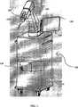
図1を参照すると、本発明の好適な実施例はロボット化された装置100を有し、以下の構成要素を含むことが分かる。ロボット化された装置100は、可動ベース110、ロボットアーム120、可動ベース内にある制御装置130を含む。上記制御装置130は、ロボットアーム120を制御して、制御装置130により外科医は、タッチスクリーン、マウス、ジョイスティック、キーボード等の上記インタフェース150の使用によりデータを入力できる。さらに、ロボット化された装置100は、ディスプレイモニタ140、ロボットアーム取り付けフランジに取付けられたツール190、力センサ180及びロボット化された装置100を手術台(図示せず)に取り付ける特定の固定装置170をも含む。 Referring to FIG. 1, it can be seen that the preferred embodiment of the present invention has a
可動ベース110は、可動ベース110が有する車輪及びハンドルによりロボット化された装置100の簡単な取り扱いを確実にする。好ましくは、可動ベース110は固定パッドまたはその等価物を備えている。 The movable base 110 ensures easy handling of the
ロボットアーム120は6関節アームである。各関節はその角度の値を計るエンコーダを備えている。これらのデータは既知の6関節の幾何図形的配置と組み合わされ、ロボットアーム取り付けフランジの位置を計算したり、ロボットアームに取り付けられたツールの位置を計算したりできる。上記ツールは、指示ツール、ガイドツールもしくは指示及びガイドツールのどちらかである。 The
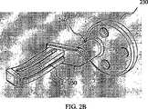
図2Aは指示ツール190を示している。指示ツール190は、ベースプレート200、ハンドル210及び指示球220から成る。 FIG. 2A shows the
図2Bは切断ガイドを示している。切断ガイドは、ベースプレート230、ハンドル240及び鋸刃をガイドするスリット250から成る。 FIG. 2B shows the cutting guide. The cutting guide includes a
図2Cは指示及びガイドツールを示している。指示及びガイドツールは、ベースプレート260、ハンドル270、鋸刃をガイドするスリット290及び指示球290から成る。 FIG. 2C shows the instruction and guide tool. The instruction and guide tool includes a
図2A から2Cまでに示されている上記ツールは、指示及び/またはガイドツールの3つの例を示しており、上記ツールは図1に示された装置で利用できる。 The above tools shown in FIGS. 2A through 2C show three examples of instruction and / or guide tools, which can be used with the apparatus shown in FIG.
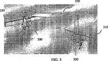
好ましくは、ロボットアーム120は、特定のベース固定装置によって動かないように手術台に取り付けられる。 Preferably, the
図3に示されるように、ベース固定装置は手術台レール310及びU字状棒材320に適合する2組のクランプ300を含む。ユーザはまず一方のクランプ300を手術台レール310上に設け、他方のクランプを可動ベースのレール330上に設ける。クランプが適当なところにあるとき、ユーザはクランプの円筒穴にU字状棒材を挿入して、クランプを所定の位置に固定(ロック)し、ノブを使ってU字状棒材をクランプ内に固定(ロック)する。 As shown in FIG. 3, the base fixation device includes two sets of
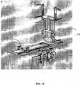
本発明の好適な実施例において、上記システムは、処置の間、足が動かないことを確実にする足固定装置(図4A、4B、4C及び4Dを参照のこと)を含む。この足固定装置は2つの高さで足を固定することができる。一つは足首の高さであり、歯があるラック(図4D)により足を固定し、もう一つは膝の高さであり、大腿骨もしくは脛骨の骨端(図4C)にネジ止めされた2本のピンにより膝の高さで足を固定する。 In a preferred embodiment of the present invention, the system includes a foot fixation device (see FIGS. 4A, 4B, 4C and 4D) that ensures that the foot does not move during the procedure. This foot fixing device can fix the foot at two heights. One is the height of the ankle, the foot is fixed by a rack with teeth (Fig. 4D), and the other is the height of the knee, screwed to the end of the femur or tibia (Fig. 4C) Fix the foot at the height of the knee with two other pins.
図4Bは足固定装置のメインプレート400を示す。メインプレート400は、2つのクランプ300により手術台に固定されている。膝固定部410及び足首固定部420は、メインプレート400に沿って摺動することができて、ネジによって所定の位置に固定できる。 FIG. 4B shows the
図4Cは患者の膝の高さで足を固定する手段の正面図である。サポート棒440上に膝を乗せる。骨は膝置換術において曝されるので、2本のピン430は大腿骨の骨端と、脛骨の骨端のどちらかにネジ止め(螺合)される。サポート棒440の位置は、垂直に調整されることができて、2つのノブにより固定することが可能である。方向は、主軸450まわりに回転することにより0度から90度まで調整可能であり、1つのノブで固定することが可能である。システム全体はプレートに沿って摺動することができる。 FIG. 4C is a front view of the means for fixing the foot at the knee height of the patient. Put your knees on the
図4Dは患者の足首の高さで足を固定する手段を示している。足をブーツ460に固定するために患者の足及び足首は、外科手術用テープもしくは他の無菌の手段により動かないように固定される。ブーツ460は運搬台470に留めることができ、この運搬台470はメインプレート400に沿って摺動し、所定の位置にノブにより固定することができる。 FIG. 4D shows the means for securing the foot at the height of the patient's ankle. To secure the foot to the
足固定装置(足首部分及び膝部分)の両方の部分が独立しているが、処置手順・処置の間、組合わされて下肢の固定を保証するために使われる。 Both parts of the foot fixation device (ankle part and knee part) are independent, but are combined to ensure the fixation of the lower limb during the treatment procedure.
本発明の好適な実施例において、制御装置130はロボットアーム120を協調・協同(働)モードに設定することができる。協調・協同(働)モードでは、ユーザがロボットアーム120の最終的な部分を把持して、手動でロボットアーム120を動かすことが可能である。図5を参照すると、本発明のシステムは、ロボットアーム取り付けフランジ125に取付けられた力センサ180を含んでいる。力センサ180は指示ツール190のようなツールを支持することができる。ユーザがツールを把持して、ある方向にそれを移動しようとするとき、制御装置130は、力センサ180によって計測される作用力を感知して、それらをロボットアーム120の位置と組み合わせてユーザが望む動きを生成する。 In a preferred embodiment of the present invention, the
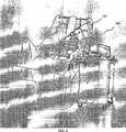
ロボット化された装置が手術台に一旦固定されると、手順・処置の最初のステップは患者の解剖学上の目印を集めることである。これらの解剖学上の目印は、外科医によって知られている。例えば、TKRの手順・処置では、脛骨上では(については)、脛骨の結節の内部、脊柱の中央及び脛骨の平坦部が集められ、大腿骨上では(については)ノッチ(notch)の中間点、関節丘の体の中心から見て遠い方と関節球の後端及び前方の外皮が集められる。図6は、患者の位置と、TKRの手順・処置における目印採集ステップを初めるときのロボット化された装置100の位置を示している。 Once the robotized device is secured to the operating table, the first step in the procedure / procedure is to collect patient anatomical landmarks. These anatomical landmarks are known by surgeons. For example, in the TKR procedure / procedure, on the tibia (for), the inside of the tibial nodule, the middle of the spine and the flat part of the tibia are collected, and on the femur (for) the midpoint of the notch. The outer skin of the joint ball and the rear end and the front skin of the joint ball are collected. FIG. 6 shows the position of the patient and the position of the
目印採集ステップの間、制御装置130がロボットアーム120を協調・協同(働)モードに設定して、ディスプレイモニタ140を介して、採集すべき目印を示す。外科医は要求されている解剖学上の目印と接するまで指示ツール190を動かして、点座標の取得をユーザインタフェース150を使用して確認する。そして制御装置130は点座標と解剖学上の重要性を記憶する。 During the mark collecting step, the
目印採集ステップの後、外科医はユーザインタフェース150を用いて計画パラメータを入力する。例えば、TKRの手順・処置では、外科医は補綴部品のモデル及びサイズを選んで、大腿骨及び脛骨の物理的な軸に対して、補綴部品の位置及び方向を決める。典型的な幾何学パラメータは、脛骨に関する内反/外反の角度、後端部の傾斜、脛骨の切除の厚さであり、大腿骨に関する内反/外反の角度、屈曲/伸展の角度、外部の回転及び大腿骨の切除の厚さである。 After the landmark collection step, the surgeon uses the user interface 150 to enter planning parameters. For example, in the TKR procedure / procedure, the surgeon selects the prosthetic component model and size to determine the position and orientation of the prosthetic component relative to the physical axes of the femur and tibia. Typical geometric parameters are the varus / valgus angle for the tibia, the slope of the posterior end, the thickness of the tibial resection, the varus / valgus angle for the femur, the flexion / extension angle, Thickness of external rotation and femoral resection.
本発明の他の実施例において、制御装置130はデータ演算処理インタフェースを含む。このデータ演算処理インタフェースは、このシステムが、ナビゲーションシステムのような、他のコンピューター補助外科手術システムに接続することを可能にする。ナビゲーションシステムは、手術前の骨の画像(CTスキャン、X線、蛍光透視法、その他)または手術中のデータとともに動作する。後者の場合、骨のデジタル化に基づいた3次元再構築アルゴリズムを使用する。ナビゲーションシステムにより得られたデータは、目印採集ステップのデータと置き換わるかまたは組み合わされる。ガイドツールの位置は、ナビゲーションシステムによって得られ、所定の通信プロトコルに従ってロボット化された装置に送られてもよい。 In another embodiment of the present invention,
要求されたガイド位置が一旦得られると、ユーザはガイドツールをロボットアームに取り付ける。好ましくは、指示及びガイドツールが使用され、その結果、ユーザは目印採集ステップと切断もしくは穴開けステップの間にツールを変える必要はない。 Once the required guide position is obtained, the user attaches the guide tool to the robot arm. Preferably, an instruction and guide tool is used so that the user does not need to change the tool between the landmark collection step and the cutting or drilling step.
ロボット化された装置100は、外科医の計画に応じて、患者の組織に対して正確にガイドを整列させる。ガイドツールが鋸刃のための切断ガイドである場合、ロボットアーム120は選択された切断面にガイドツールを維持する。ガイドツールが穴開けガイドである場合、ロボットアーム120は選択された穴開け軸に沿ってガイドツールを保持する。 The
本発明の好適な実施例において、ガイドの動きを平面内に制限するために、平面協調・協同(働)モードは、ユーザによって作動される。同様に、軸協調・協同(働)モードは、軸に沿ったガイドの動きを制限する。制御装置130が平面もしくは軸に対してロボットアームの動きを制限するとき、ユーザは、ユーザ(彼/彼女)が最適位置であると見積もるところへガイドツールを動かす。一旦この最適位置に届くと、制御装置130は所定の位置にガイドツールを保持するロボットアーム120を止める。骨の切断もしくは穴開けのような外科手術作業は、ガイドを介して従来の器具(振動鋸もしくは外科手術用ドリル)を使用する外科医によって実行される。 In a preferred embodiment of the present invention, the plane coordination / cooperation mode is activated by the user in order to limit the movement of the guide within the plane. Similarly, the axis coordination / cooperation (working) mode limits the movement of the guide along the axis. When the
TKRの手順・処置において、同じガイドツールは、脛骨の切断及び大腿骨の5カ所の切断のために使用される。脛骨骨きり術の手順・処置では、同じガイドツールが、両方の脛骨切断のために使用される。 In the TKR procedure / procedure, the same guide tool is used for cutting the tibia and 5 femurs. In the tibial osteotomy procedure / procedure, the same guide tool is used for both tibial cuts.
図7を参照すると、制御装置130は、制御ソフトウェア132を実行させており、データを制御装置130とロボット化された装置の要素との間で交換している。ソフトウェアは、ユーザインタフェース150及びディスプレイモニタ140を介してユーザと通信する。ソフトウェアは、上記したようにデータ処理インタフェースを通して、他のコンピューター補助外科手術システムと通信する。ソフトウェアは、ユーザによってかけられた作用力をロボットアームに取り付けられたツールの位置で定期的に計るために力センサ180と通信する。ソフトウェアは、ロボットアーム120の位置を制御するためにロボットアーム120と通信する。 Referring to FIG. 7, the
制御ソフトウェア132は、5つの独立モジュール134−138までから成る。好ましくは、これらのモジュールは、同時にリアルタイム環境下において動作して、制御ソフトウェアの多様な作業に対する良好な管理を保証にするために共有メモリを使用する。これらのモジュールは異なる優先度を有する。そして、安全モジュール134が最も高い優先度を有する。 The
安全モジュール134はシステム状況を監視して、危険な状態が検出されると(非常停止、ソフトウェアの機能不全、障害物との衝突、その他)、ロボットアーム120を停止する。 The
インタフェースモジュール135は、ユーザインタフェース150及びディスプレイスクリーン140を介して外科医と制御ソフトウェアの間の通信を管理する。ディスプレイスクリーン140は、手順・処置の異なったステップを通してユーザを誘導するグラフィカルインタフェースを表示する。ユーザインタフェース150は、手順・処置(目印採集を確認すること、計画パラメータを定義すること、必要な場合ロボットアームを停止すること、その他)の間、ユーザが常時制御することを可能にする。
力モジュール136は力センサ180によって計測される力及びトルクを監視する。力モジュールは障害物との衝突を検出して、安全モジュールに警告することが可能である。 The
制御モジュール137はロボットアーム120との通信を管理する。制御モジュール137は各関節のデータエンコーダ値を受信して位置命令を送る。 The
計算モジュール138は手順・処置に必要な全ての計算を行う。例えば、TKRの手順・処置では、計算モジュール138は、解剖学上の目印データと統計的なデータを組み合わせて骨の物理的な軸を再構築する。計算モジュール138はまた、運動学または逆運動学を使用してロボットアーム120の軌道を定義する。 The
本発明は上記された内容に制限されない。多様な変形が本発明の精神及び範囲から逸脱することなくなされる。 The present invention is not limited to the contents described above. Various modifications may be made without departing from the spirit and scope of the invention.
Claims (6)
Translated fromJapaneseロボットアームと少なくとも一つのツールとを含み、
前記ロボットアームは前記ツールの少なくとも一つを支持することができ、
前記少なくとも一つのツールは指示ツール及びガイドツールを含み、
前記装置は、前記ロボットアームに搭載されることができ、かつ、前記指示ツール及びガイドツールの少なくとも一つを支持することができる力センサを含み、
前記装置は、前記力センサにより計測された作用力が入力される手段を含み、
前記手段は、前記計測された作用力と前記ロボットアームの位置とを組み合わせ、協同モードで動作する場合、位置データと作用力とを組み合わせたデータに応じてユーザが望む前記ロボットアームの動作を生成し、
前記指示ツールは、解剖学上の目印の座標を得るために前記ロボットアームにより支持されており、
前記装置は、
前記指示ツールにより、前記解剖学上の目印の前記座標を手動で取得し、かつ、記憶する手段と、
取得した前記解剖学上の目印の前記座標を演算処理することにより外科手術用ツールをガイドすることができる前記ガイドツールに対して要求された位置を生成する手段と、
前記ロボットアームに取り付けられた前記ガイドツールを前記要求された位置に自動的に位置決めする手段と、を更に含むことを特徴とする装置。An image-free device for guiding a surgical tool,
A robot arm and at least one tool;
The robot arm can support at least one of the tools;
The at least one tool includes a pointing tool and a guide tool;
The device, the mounted on the robot arm is that it is, and includesa forcesensor which is capable of supporting at least one of theindication tool and guide tool,
The device includes means acting force measured by the force sensoris input,
Said means, said robot arm the combination and the measured acting force and the position of the robot arm, together when operating in thesamemode, the user in response to data obtained by combining theposition data and the acting force wants Generate the behavior of
The instruction toolis supported by said robot arm in order to obtain the landmark coordinates anatomical,
The device is
Means for manually obtaining and storing the coordinates of the anatomical landmarks with thepointing tool ;
Means for generating a position request tothe guide tool capable of guiding the surgical tool by processing theacquiredthe coordinateof the landmarks on the anatomical,
Apparatus characterized by further comprising meansfor automatically positioning the guide tool attached to the robot arm inthe requested position.
Applications Claiming Priority (3)
| Application Number | Priority Date | Filing Date | Title |
|---|---|---|---|
| FR0406491AFR2871363B1 (en) | 2004-06-15 | 2004-06-15 | ROBOTIZED GUIDING DEVICE FOR SURGICAL TOOL |
| FR0406491 | 2004-06-15 | ||
| PCT/EP2005/052751WO2005122916A1 (en) | 2004-06-15 | 2005-06-14 | An imageless robotized device and method for surgical tool guidance |
Publications (2)
| Publication Number | Publication Date |
|---|---|
| JP2008502396A JP2008502396A (en) | 2008-01-31 |
| JP4724711B2true JP4724711B2 (en) | 2011-07-13 |
Family
ID=34948907
Family Applications (1)
| Application Number | Title | Priority Date | Filing Date |
|---|---|---|---|
| JP2007515953AExpired - LifetimeJP4724711B2 (en) | 2004-06-15 | 2005-06-14 | Robotized apparatus and method without using images to guide surgical tools |
Country Status (10)
| Country | Link |
|---|---|
| US (2) | US20070156157A1 (en) |
| EP (1) | EP1755466B1 (en) |
| JP (1) | JP4724711B2 (en) |
| AT (1) | ATE381293T1 (en) |
| AU (1) | AU2005253741B2 (en) |
| CA (1) | CA2570336C (en) |
| DE (1) | DE602005003943T2 (en) |
| ES (1) | ES2297721T3 (en) |
| FR (1) | FR2871363B1 (en) |
| WO (1) | WO2005122916A1 (en) |
Families Citing this family (225)
| Publication number | Priority date | Publication date | Assignee | Title |
|---|---|---|---|---|
| TW200304608A (en) | 2002-03-06 | 2003-10-01 | Z Kat Inc | System and method for using a haptic device in combination with a computer-assisted surgery system |
| US8010180B2 (en) | 2002-03-06 | 2011-08-30 | Mako Surgical Corp. | Haptic guidance system and method |
| US11202676B2 (en) | 2002-03-06 | 2021-12-21 | Mako Surgical Corp. | Neural monitor-based dynamic haptics |
| US8996169B2 (en) | 2011-12-29 | 2015-03-31 | Mako Surgical Corp. | Neural monitor-based dynamic haptics |
| US9155544B2 (en)* | 2002-03-20 | 2015-10-13 | P Tech, Llc | Robotic systems and methods |
| US7752920B2 (en) | 2005-12-30 | 2010-07-13 | Intuitive Surgical Operations, Inc. | Modular force sensor |
| US8496647B2 (en) | 2007-12-18 | 2013-07-30 | Intuitive Surgical Operations, Inc. | Ribbed force sensor |
| US20070066917A1 (en)* | 2005-09-20 | 2007-03-22 | Hodorek Robert A | Method for simulating prosthetic implant selection and placement |
| EP2289455B1 (en)* | 2005-12-30 | 2019-11-13 | Intuitive Surgical Operations, Inc. | Modular force sensor |
| US20070156066A1 (en)* | 2006-01-03 | 2007-07-05 | Zimmer Technology, Inc. | Device for determining the shape of an anatomic surface |
| US8219178B2 (en) | 2007-02-16 | 2012-07-10 | Catholic Healthcare West | Method and system for performing invasive medical procedures using a surgical robot |
| US10357184B2 (en) | 2012-06-21 | 2019-07-23 | Globus Medical, Inc. | Surgical tool systems and method |
| US10893912B2 (en) | 2006-02-16 | 2021-01-19 | Globus Medical Inc. | Surgical tool systems and methods |
| US10653497B2 (en) | 2006-02-16 | 2020-05-19 | Globus Medical, Inc. | Surgical tool systems and methods |
| CA2644574C (en)* | 2006-03-17 | 2016-11-08 | Zimmer, Inc. | Methods of predetermining the contour of a resected bone surface and assessing the fit of a prosthesis on the bone |
| US7854765B2 (en) | 2006-04-20 | 2010-12-21 | Moskowitz Mosheh T | Electronically controlled artificial intervertebral disc with motor assisted actuation systems |
| WO2007136769A2 (en) | 2006-05-19 | 2007-11-29 | Mako Surgical Corp. | Method and apparatus for controlling a haptic device |
| US9579088B2 (en)* | 2007-02-20 | 2017-02-28 | Board Of Regents Of The University Of Nebraska | Methods, systems, and devices for surgical visualization and device manipulation |
| EP1915963A1 (en)* | 2006-10-25 | 2008-04-30 | The European Atomic Energy Community (EURATOM), represented by the European Commission | Force estimation for a minimally invasive robotic surgery system |
| WO2008118524A2 (en)* | 2007-01-26 | 2008-10-02 | Zimmer, Inc. | Instrumented linkage system |
| FR2917598B1 (en)* | 2007-06-19 | 2010-04-02 | Medtech | MULTI-APPLICATIVE ROBOTIC PLATFORM FOR NEUROSURGERY AND METHOD OF RECALING |
| GB2451498A (en) | 2007-07-31 | 2009-02-04 | Prosurgics Ltd | A motorised manipulator that accommodates manual movement of a surgical instrument |
| US9179983B2 (en) | 2007-08-14 | 2015-11-10 | Zimmer, Inc. | Method of determining a contour of an anatomical structure and selecting an orthopaedic implant to replicate the anatomical structure |
| US8486079B2 (en)* | 2007-09-11 | 2013-07-16 | Zimmer, Inc. | Method and apparatus for remote alignment of a cut guide |
| US8457790B2 (en)* | 2007-09-14 | 2013-06-04 | Zimmer, Inc. | Robotic calibration method |
| US8561473B2 (en) | 2007-12-18 | 2013-10-22 | Intuitive Surgical Operations, Inc. | Force sensor temperature compensation |
| US9895813B2 (en)* | 2008-03-31 | 2018-02-20 | Intuitive Surgical Operations, Inc. | Force and torque sensing in a surgical robot setup arm |
| DE102008057142B4 (en)* | 2008-04-29 | 2016-01-28 | Siemens Aktiengesellschaft | Method for computer-aided motion planning of a robot |
| JP2011527611A (en)* | 2008-07-08 | 2011-11-04 | パワー メディカル インターベンションズ, エルエルシー | Surgical attachment for use with robotic surgical systems |
| EP2156805B1 (en)* | 2008-08-20 | 2012-11-14 | BrainLAB AG | Planning support for correcting joint elements |
| US9610131B2 (en)* | 2008-11-05 | 2017-04-04 | The Johns Hopkins University | Rotating needle driver and apparatuses and methods related thereto |
| CN102056715B (en)* | 2009-01-09 | 2012-12-26 | 松下电器产业株式会社 | Control apparatus and control method for robot arm, robot, control program for robot arm, and integrated electronic circuit |
| US9078755B2 (en)* | 2009-02-25 | 2015-07-14 | Zimmer, Inc. | Ethnic-specific orthopaedic implants and custom cutting jigs |
| US9439691B2 (en)* | 2009-05-22 | 2016-09-13 | Clifford Tribus | Fixation-based surgery |
| US8834532B2 (en) | 2009-07-07 | 2014-09-16 | Zimmer Gmbh | Plate for the treatment of bone fractures |
| US8652148B2 (en) | 2010-02-25 | 2014-02-18 | Zimmer, Inc. | Tracked cartilage repair system |
| US8751049B2 (en)* | 2010-05-24 | 2014-06-10 | Massachusetts Institute Of Technology | Kinetic input/output |
| FR2963693B1 (en)* | 2010-08-04 | 2013-05-03 | Medtech | PROCESS FOR AUTOMATED ACQUISITION AND ASSISTED ANATOMICAL SURFACES |
| US9119655B2 (en) | 2012-08-03 | 2015-09-01 | Stryker Corporation | Surgical manipulator capable of controlling a surgical instrument in multiple modes |
| US9921712B2 (en) | 2010-12-29 | 2018-03-20 | Mako Surgical Corp. | System and method for providing substantially stable control of a surgical tool |
| US9308050B2 (en)* | 2011-04-01 | 2016-04-12 | Ecole Polytechnique Federale De Lausanne (Epfl) | Robotic system and method for spinal and other surgeries |
| WO2012131658A1 (en)* | 2011-04-01 | 2012-10-04 | Ecole Polytechnique Federale De Lausanne (Epfl) | Small active medical robot and passive holding structure |
| US10540479B2 (en)* | 2011-07-15 | 2020-01-21 | Stephen B. Murphy | Surgical planning system and method |
| FR2983059B1 (en) | 2011-11-30 | 2014-11-28 | Medtech | ROBOTIC-ASSISTED METHOD OF POSITIONING A SURGICAL INSTRUMENT IN RELATION TO THE BODY OF A PATIENT AND DEVICE FOR CARRYING OUT SAID METHOD |
| US12004905B2 (en) | 2012-06-21 | 2024-06-11 | Globus Medical, Inc. | Medical imaging systems using robotic actuators and related methods |
| US11045267B2 (en) | 2012-06-21 | 2021-06-29 | Globus Medical, Inc. | Surgical robotic automation with tracking markers |
| US10231791B2 (en) | 2012-06-21 | 2019-03-19 | Globus Medical, Inc. | Infrared signal based position recognition system for use with a robot-assisted surgery |
| US20150032164A1 (en) | 2012-06-21 | 2015-01-29 | Globus Medical, Inc. | Methods for Performing Invasive Medical Procedures Using a Surgical Robot |
| US11857266B2 (en) | 2012-06-21 | 2024-01-02 | Globus Medical, Inc. | System for a surveillance marker in robotic-assisted surgery |
| US12329593B2 (en) | 2012-06-21 | 2025-06-17 | Globus Medical, Inc. | Surgical robotic automation with tracking markers |
| US12310683B2 (en) | 2012-06-21 | 2025-05-27 | Globus Medical, Inc. | Surgical tool systems and method |
| US11607149B2 (en) | 2012-06-21 | 2023-03-21 | Globus Medical Inc. | Surgical tool systems and method |
| US11253327B2 (en) | 2012-06-21 | 2022-02-22 | Globus Medical, Inc. | Systems and methods for automatically changing an end-effector on a surgical robot |
| US12220120B2 (en) | 2012-06-21 | 2025-02-11 | Globus Medical, Inc. | Surgical robotic system with retractor |
| US11864745B2 (en) | 2012-06-21 | 2024-01-09 | Globus Medical, Inc. | Surgical robotic system with retractor |
| US11317971B2 (en) | 2012-06-21 | 2022-05-03 | Globus Medical, Inc. | Systems and methods related to robotic guidance in surgery |
| US11864839B2 (en) | 2012-06-21 | 2024-01-09 | Globus Medical Inc. | Methods of adjusting a virtual implant and related surgical navigation systems |
| US11399900B2 (en) | 2012-06-21 | 2022-08-02 | Globus Medical, Inc. | Robotic systems providing co-registration using natural fiducials and related methods |
| US11974822B2 (en) | 2012-06-21 | 2024-05-07 | Globus Medical Inc. | Method for a surveillance marker in robotic-assisted surgery |
| US11298196B2 (en) | 2012-06-21 | 2022-04-12 | Globus Medical Inc. | Surgical robotic automation with tracking markers and controlled tool advancement |
| US11116576B2 (en) | 2012-06-21 | 2021-09-14 | Globus Medical Inc. | Dynamic reference arrays and methods of use |
| US10758315B2 (en) | 2012-06-21 | 2020-09-01 | Globus Medical Inc. | Method and system for improving 2D-3D registration convergence |
| US10136954B2 (en) | 2012-06-21 | 2018-11-27 | Globus Medical, Inc. | Surgical tool systems and method |
| US10350013B2 (en) | 2012-06-21 | 2019-07-16 | Globus Medical, Inc. | Surgical tool systems and methods |
| US10624710B2 (en) | 2012-06-21 | 2020-04-21 | Globus Medical, Inc. | System and method for measuring depth of instrumentation |
| US12262954B2 (en) | 2012-06-21 | 2025-04-01 | Globus Medical, Inc. | Surgical robotic automation with tracking markers |
| US11395706B2 (en) | 2012-06-21 | 2022-07-26 | Globus Medical Inc. | Surgical robot platform |
| US11857149B2 (en) | 2012-06-21 | 2024-01-02 | Globus Medical, Inc. | Surgical robotic systems with target trajectory deviation monitoring and related methods |
| EP2863827B1 (en) | 2012-06-21 | 2022-11-16 | Globus Medical, Inc. | Surgical robot platform |
| US11793570B2 (en) | 2012-06-21 | 2023-10-24 | Globus Medical Inc. | Surgical robotic automation with tracking markers |
| CN107198567B (en)* | 2012-08-03 | 2021-02-09 | 史赛克公司 | Systems and methods for robotic surgery |
| US9820818B2 (en) | 2012-08-03 | 2017-11-21 | Stryker Corporation | System and method for controlling a surgical manipulator based on implant parameters |
| US9226796B2 (en) | 2012-08-03 | 2016-01-05 | Stryker Corporation | Method for detecting a disturbance as an energy applicator of a surgical instrument traverses a cutting path |
| WO2014198796A1 (en) | 2013-06-11 | 2014-12-18 | Minmaxmedical | System for positioning a surgical device |
| US9283048B2 (en) | 2013-10-04 | 2016-03-15 | KB Medical SA | Apparatus and systems for precise guidance of surgical tools |
| WO2015103010A1 (en)* | 2013-12-31 | 2015-07-09 | Mako Surgical Corp. | Systems and methods for preparing a proximal tibia |
| DE102014100131A1 (en)* | 2014-01-08 | 2015-07-09 | Aesculap Ag | Surgical instruments and procedures |
| US9241771B2 (en) | 2014-01-15 | 2016-01-26 | KB Medical SA | Notched apparatus for guidance of an insertable instrument along an axis during spinal surgery |
| WO2015121311A1 (en) | 2014-02-11 | 2015-08-20 | KB Medical SA | Sterile handle for controlling a robotic surgical system from a sterile field |
| EP3134022B1 (en) | 2014-04-24 | 2018-01-10 | KB Medical SA | Surgical instrument holder for use with a robotic surgical system |
| CN106999248B (en) | 2014-06-19 | 2021-04-06 | Kb医疗公司 | Systems and methods for performing minimally invasive surgery |
| US10357257B2 (en) | 2014-07-14 | 2019-07-23 | KB Medical SA | Anti-skid surgical instrument for use in preparing holes in bone tissue |
| JP6416560B2 (en)* | 2014-09-11 | 2018-10-31 | 株式会社デンソー | Positioning control device |
| US20160081753A1 (en)* | 2014-09-18 | 2016-03-24 | KB Medical SA | Robot-Mounted User Interface For Interacting With Operation Room Equipment |
| US9815206B2 (en) | 2014-09-25 | 2017-11-14 | The Johns Hopkins University | Surgical system user interface using cooperatively-controlled robot |
| EP3226781B1 (en) | 2014-12-02 | 2018-08-01 | KB Medical SA | Robot assisted volume removal during surgery |
| US9739674B2 (en)* | 2015-01-09 | 2017-08-22 | Stryker Corporation | Isolated force/torque sensor assembly for force controlled robot |
| US10013808B2 (en) | 2015-02-03 | 2018-07-03 | Globus Medical, Inc. | Surgeon head-mounted display apparatuses |
| WO2016131903A1 (en) | 2015-02-18 | 2016-08-25 | KB Medical SA | Systems and methods for performing minimally invasive spinal surgery with a robotic surgical system using a percutaneous technique |
| DE102015205214A1 (en)* | 2015-03-23 | 2016-09-29 | Universität Siegen | A method for an integrated operation planning and support system for operations on the human or animal body and a device therefor |
| US10959783B2 (en) | 2015-04-15 | 2021-03-30 | Mobius Imaging, Llc | Integrated medical imaging and surgical robotic system |
| CN104739462A (en)* | 2015-04-24 | 2015-07-01 | 杨明 | Surgical operation system |
| US10646298B2 (en) | 2015-07-31 | 2020-05-12 | Globus Medical, Inc. | Robot arm and methods of use |
| US10058394B2 (en) | 2015-07-31 | 2018-08-28 | Globus Medical, Inc. | Robot arm and methods of use |
| US10080615B2 (en) | 2015-08-12 | 2018-09-25 | Globus Medical, Inc. | Devices and methods for temporary mounting of parts to bone |
| JP6894431B2 (en) | 2015-08-31 | 2021-06-30 | ケービー メディカル エスアー | Robotic surgical system and method |
| CN105078540A (en)* | 2015-09-06 | 2015-11-25 | 陈�峰 | Brain surgery assisting apparatus for neurosurgery |
| US10034716B2 (en) | 2015-09-14 | 2018-07-31 | Globus Medical, Inc. | Surgical robotic systems and methods thereof |
| US9771092B2 (en) | 2015-10-13 | 2017-09-26 | Globus Medical, Inc. | Stabilizer wheel assembly and methods of use |
| WO2017083453A1 (en) | 2015-11-12 | 2017-05-18 | Covidien Lp | Robotic surgical systems and methods for monitoring applied forces |
| US12082893B2 (en) | 2015-11-24 | 2024-09-10 | Think Surgical, Inc. | Robotic pin placement |
| JP6934861B2 (en) | 2015-11-24 | 2021-09-15 | シンク サージカル, インコーポレイテッド | Active robot pin placement in total knee osteoarthritis |
| US12178532B2 (en) | 2015-11-24 | 2024-12-31 | Think Surgical, Inc. | Robotic alignment of a tool or pin with a virtual plane |
| US12220137B2 (en) | 2015-11-24 | 2025-02-11 | Think Surgical, Inc. | Cut guide for arthroplasty procedures |
| US11883217B2 (en) | 2016-02-03 | 2024-01-30 | Globus Medical, Inc. | Portable medical imaging system and method |
| US11058378B2 (en) | 2016-02-03 | 2021-07-13 | Globus Medical, Inc. | Portable medical imaging system |
| US10117632B2 (en) | 2016-02-03 | 2018-11-06 | Globus Medical, Inc. | Portable medical imaging system with beam scanning collimator |
| US10842453B2 (en) | 2016-02-03 | 2020-11-24 | Globus Medical, Inc. | Portable medical imaging system |
| US10448910B2 (en) | 2016-02-03 | 2019-10-22 | Globus Medical, Inc. | Portable medical imaging system |
| US11064904B2 (en) | 2016-02-29 | 2021-07-20 | Extremity Development Company, Llc | Smart drill, jig, and method of orthopedic surgery |
| US10866119B2 (en) | 2016-03-14 | 2020-12-15 | Globus Medical, Inc. | Metal detector for detecting insertion of a surgical device into a hollow tube |
| WO2017176440A1 (en)* | 2016-04-06 | 2017-10-12 | Think Surgical, Inc. | Robotic system with end-effector overhang control |
| EP3241518B1 (en) | 2016-04-11 | 2024-10-23 | Globus Medical, Inc | Surgical tool systems |
| US11229489B2 (en) | 2016-06-16 | 2022-01-25 | Zimmer, Inc. | Soft tissue balancing in articular surgery |
| WO2017218933A1 (en) | 2016-06-16 | 2017-12-21 | Medtech S.A. | Robotized system for femoroacetabular impingement resurfacing |
| US10136952B2 (en) | 2016-06-16 | 2018-11-27 | Zimmer, Inc. | Soft tissue balancing in articular surgery |
| CN114469211A (en) | 2016-07-12 | 2022-05-13 | 莫比乌斯成像公司 | Multistage dilator and cannula system and method |
| EP3512450A4 (en) | 2016-09-16 | 2020-11-04 | Mobius Imaging LLC | System and method for mounting a robotic arm in a surgical robotic system |
| CN111417352B (en) | 2016-10-21 | 2024-05-24 | 莫比乌斯成像公司 | Method and system for setting trajectory and target location for image guided surgery |
| US11751948B2 (en) | 2016-10-25 | 2023-09-12 | Mobius Imaging, Llc | Methods and systems for robot-assisted surgery |
| WO2018076114A1 (en) | 2016-10-28 | 2018-05-03 | Orthosoft Inc. | Robotic cutting workflow |
| AU2017372744B2 (en) | 2016-12-08 | 2020-03-26 | Orthotaxy | Surgical system for cutting an anatomical structure according to at least one target plane |
| US11607229B2 (en) | 2016-12-08 | 2023-03-21 | Orthotaxy S.A.S. | Surgical system for cutting an anatomical structure according to at least one target plane |
| EP3551098B1 (en) | 2016-12-08 | 2024-03-20 | Orthotaxy | Surgical system for cutting an anatomical structure according to at least one target cutting plane |
| DK201600146U4 (en)* | 2016-12-13 | 2018-03-23 | EasyRobotics ApS | robotic Workstation |
| US11202682B2 (en) | 2016-12-16 | 2021-12-21 | Mako Surgical Corp. | Techniques for modifying tool operation in a surgical robotic system based on comparing actual and commanded states of the tool relative to a surgical site |
| JP7233841B2 (en) | 2017-01-18 | 2023-03-07 | ケービー メディカル エスアー | Robotic Navigation for Robotic Surgical Systems |
| CN106880408B (en)* | 2017-03-10 | 2023-04-18 | 首都医科大学宣武医院 | Force line positioner for high tibial osteotomy |
| US11071594B2 (en) | 2017-03-16 | 2021-07-27 | KB Medical SA | Robotic navigation of robotic surgical systems |
| US10682129B2 (en)* | 2017-03-23 | 2020-06-16 | Mobius Imaging, Llc | Robotic end effector with adjustable inner diameter |
| US11033341B2 (en) | 2017-05-10 | 2021-06-15 | Mako Surgical Corp. | Robotic spine surgery system and methods |
| WO2018209042A2 (en) | 2017-05-10 | 2018-11-15 | Mako Surgical Corp. | Robotic spine surgery system and methods |
| US11135015B2 (en) | 2017-07-21 | 2021-10-05 | Globus Medical, Inc. | Robot surgical platform |
| US11660145B2 (en) | 2017-08-11 | 2023-05-30 | Mobius Imaging Llc | Method and apparatus for attaching a reference marker to a patient |
| CA2977489C (en)* | 2017-08-28 | 2019-11-26 | Synaptive Medical (Barbados) Inc. | Positioning arm for a surgical navigation system |
| US11166775B2 (en) | 2017-09-15 | 2021-11-09 | Mako Surgical Corp. | Robotic cutting systems and methods for surgical saw blade cutting on hard tissue |
| US10835288B2 (en) | 2017-09-20 | 2020-11-17 | Medtech S.A. | Devices and methods of accelerating bone cuts |
| EP3691545A4 (en) | 2017-10-04 | 2022-02-16 | Mobius Imaging, LLC | SYSTEMS AND METHODS FOR PERFORMING SPINAL SURGERY WITH LATERAL APPROACH |
| AU2018346790B2 (en) | 2017-10-05 | 2024-09-26 | Mobius Imaging, Llc | Methods and systems for performing computer assisted surgery |
| WO2019083983A2 (en) | 2017-10-23 | 2019-05-02 | Bono Peter L | Rotary oscillating/reciprocating surgical tool |
| EP3492032B1 (en) | 2017-11-09 | 2023-01-04 | Globus Medical, Inc. | Surgical robotic systems for bending surgical rods |
| US11794338B2 (en) | 2017-11-09 | 2023-10-24 | Globus Medical Inc. | Robotic rod benders and related mechanical and motor housings |
| US11357548B2 (en) | 2017-11-09 | 2022-06-14 | Globus Medical, Inc. | Robotic rod benders and related mechanical and motor housings |
| US11134862B2 (en) | 2017-11-10 | 2021-10-05 | Globus Medical, Inc. | Methods of selecting surgical implants and related devices |
| US11039892B2 (en)* | 2017-12-22 | 2021-06-22 | Zimmer, Inc. | Robotically-assisted knee arthroplasty support systems and methods |
| US10999493B2 (en) | 2017-12-22 | 2021-05-04 | Medtech S.A. | Scialytic light navigation |
| CN118662240A (en) | 2018-01-26 | 2024-09-20 | 马科外科公司 | End effector, system, and method for impacting a prosthesis guided by a surgical robot |
| US20190254753A1 (en) | 2018-02-19 | 2019-08-22 | Globus Medical, Inc. | Augmented reality navigation systems for use with robotic surgical systems and methods of their use |
| US10573023B2 (en) | 2018-04-09 | 2020-02-25 | Globus Medical, Inc. | Predictive visualization of medical imaging scanner component movement |
| US11337742B2 (en) | 2018-11-05 | 2022-05-24 | Globus Medical Inc | Compliant orthopedic driver |
| US11278360B2 (en) | 2018-11-16 | 2022-03-22 | Globus Medical, Inc. | End-effectors for surgical robotic systems having sealed optical components |
| US11744655B2 (en) | 2018-12-04 | 2023-09-05 | Globus Medical, Inc. | Drill guide fixtures, cranial insertion fixtures, and related methods and robotic systems |
| US11602402B2 (en) | 2018-12-04 | 2023-03-14 | Globus Medical, Inc. | Drill guide fixtures, cranial insertion fixtures, and related methods and robotic systems |
| USD932024S1 (en)* | 2018-12-28 | 2021-09-28 | Tinavi Medical Technologies Co., Ltd. | Surgical robot |
| US12349982B2 (en) | 2019-02-21 | 2025-07-08 | Surgical Targeted Solutions Inc. | Instrument bourne optical time of flight kinematic position sensing system for precision targeting and methods of surgery |
| US11918313B2 (en) | 2019-03-15 | 2024-03-05 | Globus Medical Inc. | Active end effectors for surgical robots |
| US20200297357A1 (en) | 2019-03-22 | 2020-09-24 | Globus Medical, Inc. | System for neuronavigation registration and robotic trajectory guidance, robotic surgery, and related methods and devices |
| US11382549B2 (en) | 2019-03-22 | 2022-07-12 | Globus Medical, Inc. | System for neuronavigation registration and robotic trajectory guidance, and related methods and devices |
| US11317978B2 (en) | 2019-03-22 | 2022-05-03 | Globus Medical, Inc. | System for neuronavigation registration and robotic trajectory guidance, robotic surgery, and related methods and devices |
| US11419616B2 (en) | 2019-03-22 | 2022-08-23 | Globus Medical, Inc. | System for neuronavigation registration and robotic trajectory guidance, robotic surgery, and related methods and devices |
| US11806084B2 (en) | 2019-03-22 | 2023-11-07 | Globus Medical, Inc. | System for neuronavigation registration and robotic trajectory guidance, and related methods and devices |
| US11571265B2 (en) | 2019-03-22 | 2023-02-07 | Globus Medical Inc. | System for neuronavigation registration and robotic trajectory guidance, robotic surgery, and related methods and devices |
| EP4483833A3 (en) | 2019-04-12 | 2025-03-19 | MAKO Surgical Corp. | Robotic systems for manipulating a cutting guide for a surgical instrument |
| FR3095331A1 (en)* | 2019-04-26 | 2020-10-30 | Ganymed Robotics | Computer-assisted orthopedic surgery procedure |
| US11045179B2 (en) | 2019-05-20 | 2021-06-29 | Global Medical Inc | Robot-mounted retractor system |
| CA3142222A1 (en)* | 2019-05-31 | 2020-12-03 | Ganymed Robotics | Lockable surgical system |
| US11628023B2 (en) | 2019-07-10 | 2023-04-18 | Globus Medical, Inc. | Robotic navigational system for interbody implants |
| US12396692B2 (en) | 2019-09-24 | 2025-08-26 | Globus Medical, Inc. | Compound curve cable chain |
| US11571171B2 (en) | 2019-09-24 | 2023-02-07 | Globus Medical, Inc. | Compound curve cable chain |
| US12329391B2 (en) | 2019-09-27 | 2025-06-17 | Globus Medical, Inc. | Systems and methods for robot-assisted knee arthroplasty surgery |
| US11426178B2 (en) | 2019-09-27 | 2022-08-30 | Globus Medical Inc. | Systems and methods for navigating a pin guide driver |
| US11890066B2 (en) | 2019-09-30 | 2024-02-06 | Globus Medical, Inc | Surgical robot with passive end effector |
| US11864857B2 (en) | 2019-09-27 | 2024-01-09 | Globus Medical, Inc. | Surgical robot with passive end effector |
| US12408929B2 (en) | 2019-09-27 | 2025-09-09 | Globus Medical, Inc. | Systems and methods for navigating a pin guide driver |
| US11510684B2 (en) | 2019-10-14 | 2022-11-29 | Globus Medical, Inc. | Rotary motion passive end effector for surgical robots in orthopedic surgeries |
| US11992373B2 (en) | 2019-12-10 | 2024-05-28 | Globus Medical, Inc | Augmented reality headset with varied opacity for navigated robotic surgery |
| US12133772B2 (en) | 2019-12-10 | 2024-11-05 | Globus Medical, Inc. | Augmented reality headset for navigated robotic surgery |
| US12220176B2 (en) | 2019-12-10 | 2025-02-11 | Globus Medical, Inc. | Extended reality instrument interaction zone for navigated robotic |
| US12064189B2 (en) | 2019-12-13 | 2024-08-20 | Globus Medical, Inc. | Navigated instrument for use in robotic guided surgery |
| US11382699B2 (en) | 2020-02-10 | 2022-07-12 | Globus Medical Inc. | Extended reality visualization of optical tool tracking volume for computer assisted navigation in surgery |
| US12414752B2 (en) | 2020-02-17 | 2025-09-16 | Globus Medical, Inc. | System and method of determining optimal 3-dimensional position and orientation of imaging device for imaging patient bones |
| US11207150B2 (en) | 2020-02-19 | 2021-12-28 | Globus Medical, Inc. | Displaying a virtual model of a planned instrument attachment to ensure correct selection of physical instrument attachment |
| US12376868B2 (en) | 2020-04-16 | 2025-08-05 | Orthosoft Ulc | Devices and methods for posterior resection in robotically assisted partial knee arthroplasties |
| CA3114820C (en)* | 2020-04-16 | 2023-10-03 | Orthosoft Ulc | Devices and methods for posterior resection in robotically assisted partial knee arthroplasties |
| US11253216B2 (en) | 2020-04-28 | 2022-02-22 | Globus Medical Inc. | Fixtures for fluoroscopic imaging systems and related navigation systems and methods |
| US11382700B2 (en) | 2020-05-08 | 2022-07-12 | Globus Medical Inc. | Extended reality headset tool tracking and control |
| US11510750B2 (en) | 2020-05-08 | 2022-11-29 | Globus Medical, Inc. | Leveraging two-dimensional digital imaging and communication in medicine imagery in three-dimensional extended reality applications |
| US11153555B1 (en) | 2020-05-08 | 2021-10-19 | Globus Medical Inc. | Extended reality headset camera system for computer assisted navigation in surgery |
| US12070276B2 (en) | 2020-06-09 | 2024-08-27 | Globus Medical Inc. | Surgical object tracking in visible light via fiducial seeding and synthetic image registration |
| US11317973B2 (en) | 2020-06-09 | 2022-05-03 | Globus Medical, Inc. | Camera tracking bar for computer assisted navigation during surgery |
| US11382713B2 (en) | 2020-06-16 | 2022-07-12 | Globus Medical, Inc. | Navigated surgical system with eye to XR headset display calibration |
| US11877807B2 (en) | 2020-07-10 | 2024-01-23 | Globus Medical, Inc | Instruments for navigated orthopedic surgeries |
| US11793588B2 (en) | 2020-07-23 | 2023-10-24 | Globus Medical, Inc. | Sterile draping of robotic arms |
| US11737831B2 (en) | 2020-09-02 | 2023-08-29 | Globus Medical Inc. | Surgical object tracking template generation for computer assisted navigation during surgical procedure |
| US11523785B2 (en) | 2020-09-24 | 2022-12-13 | Globus Medical, Inc. | Increased cone beam computed tomography volume length without requiring stitching or longitudinal C-arm movement |
| USD993420S1 (en)* | 2020-09-30 | 2023-07-25 | Karl Storz Se & Co. Kg | Robotic arm for exoscopes |
| US12076091B2 (en) | 2020-10-27 | 2024-09-03 | Globus Medical, Inc. | Robotic navigational system |
| US11911112B2 (en) | 2020-10-27 | 2024-02-27 | Globus Medical, Inc. | Robotic navigational system |
| EP4236851A1 (en) | 2020-10-30 | 2023-09-06 | MAKO Surgical Corp. | Robotic surgical system with slingshot prevention |
| US11941814B2 (en) | 2020-11-04 | 2024-03-26 | Globus Medical Inc. | Auto segmentation using 2-D images taken during 3-D imaging spin |
| US11717350B2 (en) | 2020-11-24 | 2023-08-08 | Globus Medical Inc. | Methods for robotic assistance and navigation in spinal surgery and related systems |
| US11980415B2 (en) | 2020-12-11 | 2024-05-14 | Nuvasive, Inc. | Robotic surgery |
| US12161433B2 (en) | 2021-01-08 | 2024-12-10 | Globus Medical, Inc. | System and method for ligament balancing with robotic assistance |
| US12029516B2 (en) | 2021-02-11 | 2024-07-09 | Mako Surgical Corp. | Robotic manipulator comprising isolation mechanism for force/torque sensor |
| US12150728B2 (en) | 2021-04-14 | 2024-11-26 | Globus Medical, Inc. | End effector for a surgical robot |
| US12178523B2 (en) | 2021-04-19 | 2024-12-31 | Globus Medical, Inc. | Computer assisted surgical navigation system for spine procedures |
| CA3163352A1 (en)* | 2021-06-15 | 2022-12-15 | Orthosoft Ulc | Tracking system for robotized computer-assisted surgery |
| US11857273B2 (en) | 2021-07-06 | 2024-01-02 | Globus Medical, Inc. | Ultrasonic robotic surgical navigation |
| US11439444B1 (en) | 2021-07-22 | 2022-09-13 | Globus Medical, Inc. | Screw tower and rod reduction tool |
| USD1044829S1 (en) | 2021-07-29 | 2024-10-01 | Mako Surgical Corp. | Display screen or portion thereof with graphical user interface |
| US12213745B2 (en) | 2021-09-16 | 2025-02-04 | Globus Medical, Inc. | Extended reality systems for visualizing and controlling operating room equipment |
| US12184636B2 (en) | 2021-10-04 | 2024-12-31 | Globus Medical, Inc. | Validating credential keys based on combinations of credential value strings and input order strings |
| US12238087B2 (en) | 2021-10-04 | 2025-02-25 | Globus Medical, Inc. | Validating credential keys based on combinations of credential value strings and input order strings |
| US20230368330A1 (en) | 2021-10-20 | 2023-11-16 | Globus Medical, Inc. | Interpolation of medical images |
| US20230165639A1 (en) | 2021-12-01 | 2023-06-01 | Globus Medical, Inc. | Extended reality systems with three-dimensional visualizations of medical image scan slices |
| US11911115B2 (en) | 2021-12-20 | 2024-02-27 | Globus Medical Inc. | Flat panel registration fixture and method of using same |
| US12103480B2 (en) | 2022-03-18 | 2024-10-01 | Globus Medical Inc. | Omni-wheel cable pusher |
| US12048493B2 (en) | 2022-03-31 | 2024-07-30 | Globus Medical, Inc. | Camera tracking system identifying phantom markers during computer assisted surgery navigation |
| US12394086B2 (en) | 2022-05-10 | 2025-08-19 | Globus Medical, Inc. | Accuracy check and automatic calibration of tracked instruments |
| US12161427B2 (en) | 2022-06-08 | 2024-12-10 | Globus Medical, Inc. | Surgical navigation system with flat panel registration fixture |
| US20240020840A1 (en) | 2022-07-15 | 2024-01-18 | Globus Medical, Inc. | REGISTRATION OF 3D and 2D IMAGES FOR SURGICAL NAVIGATION AND ROBOTIC GUIDANCE WITHOUT USING RADIOPAQUE FIDUCIALS IN THE IMAGES |
| US12226169B2 (en) | 2022-07-15 | 2025-02-18 | Globus Medical, Inc. | Registration of 3D and 2D images for surgical navigation and robotic guidance without using radiopaque fiducials in the images |
| CN115008478B (en)* | 2022-08-09 | 2022-10-25 | 北京航空航天大学 | Method and system for selecting grabbing pose of double-arm robot and storage medium |
| US12318150B2 (en) | 2022-10-11 | 2025-06-03 | Globus Medical Inc. | Camera tracking system for computer assisted surgery navigation |
| US20240138932A1 (en)* | 2022-10-28 | 2024-05-02 | Warsaw Orthopedic, Inc. | Systems and methods for controlling one or more surgical tools |
Family Cites Families (83)
| Publication number | Priority date | Publication date | Assignee | Title |
|---|---|---|---|---|
| US5030237A (en)* | 1983-06-24 | 1991-07-09 | Queen's University At Kingston | Elbow prosthesis |
| US4549540A (en)* | 1983-11-16 | 1985-10-29 | Precision Surgical Instruments, Inc. | Thigh restraining apparatus and method |
| US5078140A (en)* | 1986-05-08 | 1992-01-07 | Kwoh Yik S | Imaging device - aided robotic stereotaxis system |
| US5251127A (en)* | 1988-02-01 | 1993-10-05 | Faro Medical Technologies Inc. | Computer-aided surgery apparatus |
| EP0326768A3 (en)* | 1988-02-01 | 1991-01-23 | Faro Medical Technologies Inc. | Computer-aided surgery apparatus |
| US4979949A (en)* | 1988-04-26 | 1990-12-25 | The Board Of Regents Of The University Of Washington | Robot-aided system for surgery |
| US4913413A (en)* | 1989-06-09 | 1990-04-03 | Faro Medical Technologies Inc. | Universal leg holder |
| US5086401A (en)* | 1990-05-11 | 1992-02-04 | International Business Machines Corporation | Image-directed robotic system for precise robotic surgery including redundant consistency checking |
| US5279309A (en)* | 1991-06-13 | 1994-01-18 | International Business Machines Corporation | Signaling device and method for monitoring positions in a surgical operation |
| US5230623A (en)* | 1991-12-10 | 1993-07-27 | Radionics, Inc. | Operating pointer with interactive computergraphics |
| CA2128606C (en)* | 1992-01-21 | 2008-07-22 | Philip S. Green | Teleoperator system and method with telepresence |
| FR2691093B1 (en)* | 1992-05-12 | 1996-06-14 | Univ Joseph Fourier | ROBOT FOR GUIDANCE OF GESTURES AND CONTROL METHOD. |
| US5657429A (en)* | 1992-08-10 | 1997-08-12 | Computer Motion, Inc. | Automated endoscope system optimal positioning |
| US5524180A (en)* | 1992-08-10 | 1996-06-04 | Computer Motion, Inc. | Automated endoscope system for optimal positioning |
| US5427097A (en)* | 1992-12-10 | 1995-06-27 | Accuray, Inc. | Apparatus for and method of carrying out stereotaxic radiosurgery and radiotherapy |
| WO1994014366A2 (en)* | 1992-12-28 | 1994-07-07 | Synvasive Technology, Inc. | Surgical cutting block and method of use |
| US6406472B1 (en)* | 1993-05-14 | 2002-06-18 | Sri International, Inc. | Remote center positioner |
| JPH07184929A (en)* | 1993-12-27 | 1995-07-25 | Olympus Optical Co Ltd | Surgical instrument |
| GB9405299D0 (en)* | 1994-03-17 | 1994-04-27 | Roke Manor Research | Improvements in or relating to video-based systems for computer assisted surgery and localisation |
| ATE228338T1 (en)* | 1994-10-07 | 2002-12-15 | Univ St Louis | SURGICAL NAVIGATION ARRANGEMENT INCLUDING REFERENCE AND LOCATION SYSTEMS |
| US5540696A (en)* | 1995-01-06 | 1996-07-30 | Zimmer, Inc. | Instrumentation for use in orthopaedic surgery |
| US5887121A (en)* | 1995-04-21 | 1999-03-23 | International Business Machines Corporation | Method of constrained Cartesian control of robotic mechanisms with active and passive joints |
| US5814038A (en)* | 1995-06-07 | 1998-09-29 | Sri International | Surgical manipulator for a telerobotic system |
| US5846081A (en)* | 1995-08-23 | 1998-12-08 | Bushway; Geoffrey C. | Computerized instrument platform positioning system |
| US5828813A (en)* | 1995-09-07 | 1998-10-27 | California Institute Of Technology | Six axis force feedback input device |
| US5806518A (en)* | 1995-09-11 | 1998-09-15 | Integrated Surgical Systems | Method and system for positioning surgical robot |
| US5772594A (en)* | 1995-10-17 | 1998-06-30 | Barrick; Earl F. | Fluoroscopic image guided orthopaedic surgery system with intraoperative registration |
| US5682886A (en)* | 1995-12-26 | 1997-11-04 | Musculographics Inc | Computer-assisted surgical system |
| US5799055A (en)* | 1996-05-15 | 1998-08-25 | Northwestern University | Apparatus and method for planning a stereotactic surgical procedure using coordinated fluoroscopy |
| IT1289301B1 (en)* | 1996-10-31 | 1998-10-02 | Scuola Superiore Di Studi Universitari E Di Perfezionamento Sant Anna | MANUAL DRILL FOR ORTHOPEDIC USE WITH INCIPIENT ADVANCE AND BREAK-OUT CONTROL |
| US6132368A (en)* | 1996-12-12 | 2000-10-17 | Intuitive Surgical, Inc. | Multi-component telepresence system and method |
| US6331181B1 (en)* | 1998-12-08 | 2001-12-18 | Intuitive Surgical, Inc. | Surgical robotic tools, data architecture, and use |
| US6205411B1 (en)* | 1997-02-21 | 2001-03-20 | Carnegie Mellon University | Computer-assisted surgery planner and intra-operative guidance system |
| DE29704393U1 (en)* | 1997-03-11 | 1997-07-17 | Aesculap Ag, 78532 Tuttlingen | Device for preoperative determination of the position data of endoprosthesis parts |
| US5921992A (en)* | 1997-04-11 | 1999-07-13 | Radionics, Inc. | Method and system for frameless tool calibration |
| US6434507B1 (en)* | 1997-09-05 | 2002-08-13 | Surgical Navigation Technologies, Inc. | Medical instrument and method for use with computer-assisted image guided surgery |
| US6096050A (en)* | 1997-09-19 | 2000-08-01 | Surgical Navigation Specialist Inc. | Method and apparatus for correlating a body with an image of the body |
| US6714839B2 (en)* | 1998-12-08 | 2004-03-30 | Intuitive Surgical, Inc. | Master having redundant degrees of freedom |
| DE19747427C2 (en)* | 1997-10-28 | 1999-12-09 | Zeiss Carl Fa | Device for bone segment navigation |
| US6348058B1 (en)* | 1997-12-12 | 2002-02-19 | Surgical Navigation Technologies, Inc. | Image guided spinal surgery guide, system, and method for use thereof |
| US6228089B1 (en)* | 1997-12-19 | 2001-05-08 | Depuy International Limited | Device for positioning and guiding a surgical instrument during orthopaedic interventions |
| US6949106B2 (en)* | 1998-02-24 | 2005-09-27 | Endovia Medical, Inc. | Surgical instrument |
| US6197017B1 (en)* | 1998-02-24 | 2001-03-06 | Brock Rogers Surgical, Inc. | Articulated apparatus for telemanipulator system |
| DE19814630B4 (en)* | 1998-03-26 | 2011-09-29 | Carl Zeiss | Method and apparatus for manually controlled guiding a tool in a predetermined range of motion |
| SE9801168L (en)* | 1998-04-01 | 1999-07-12 | Stig Lindequist | Method and apparatus for determining the position of fixation means in hip fracture |
| US6233504B1 (en)* | 1998-04-16 | 2001-05-15 | California Institute Of Technology | Tool actuation and force feedback on robot-assisted microsurgery system |
| ATE272365T1 (en)* | 1998-05-28 | 2004-08-15 | Orthosoft Inc | INTERACTIVE AND COMPUTER-ASSISTED SURGICAL SYSTEM |
| US6033415A (en)* | 1998-09-14 | 2000-03-07 | Integrated Surgical Systems | System and method for performing image directed robotic orthopaedic procedures without a fiducial reference system |
| US6659939B2 (en)* | 1998-11-20 | 2003-12-09 | Intuitive Surgical, Inc. | Cooperative minimally invasive telesurgical system |
| US6620173B2 (en)* | 1998-12-08 | 2003-09-16 | Intuitive Surgical, Inc. | Method for introducing an end effector to a surgical site in minimally invasive surgery |
| US6322567B1 (en)* | 1998-12-14 | 2001-11-27 | Integrated Surgical Systems, Inc. | Bone motion tracking system |
| US6430434B1 (en)* | 1998-12-14 | 2002-08-06 | Integrated Surgical Systems, Inc. | Method for determining the location and orientation of a bone for computer-assisted orthopedic procedures using intraoperatively attached markers |
| WO2000038571A1 (en)* | 1998-12-31 | 2000-07-06 | Ball Semiconductor, Inc. | Position sensing system |
| US6470207B1 (en)* | 1999-03-23 | 2002-10-22 | Surgical Navigation Technologies, Inc. | Navigational guidance via computer-assisted fluoroscopic imaging |
| US6491699B1 (en)* | 1999-04-20 | 2002-12-10 | Surgical Navigation Technologies, Inc. | Instrument guidance method and system for image guided surgery |
| US6471710B1 (en)* | 1999-08-13 | 2002-10-29 | Advanced Sensor Technology, Llc | Probe position sensing system and method of employment of same |
| US6312435B1 (en)* | 1999-10-08 | 2001-11-06 | Intuitive Surgical, Inc. | Surgical instrument with extended reach for use in minimally invasive surgery |
| US20040034340A1 (en)* | 1999-10-13 | 2004-02-19 | Spineco, Inc., An Ohio Corporation | Smart dissector |
| JP3268357B2 (en)* | 2000-01-13 | 2002-03-25 | 独立行政法人産業技術総合研究所 | Link mechanism that defines position and direction |
| US6702821B2 (en)* | 2000-01-14 | 2004-03-09 | The Bonutti 2003 Trust A | Instrumentation for minimally invasive joint replacement and methods for using same |
| ES2553715T3 (en)* | 2000-03-10 | 2015-12-11 | Smith & Nephew, Inc. | Apparatus for use in arthroplasty in a knee joint |
| JP2003534035A (en)* | 2000-03-15 | 2003-11-18 | オーソソフト インコーポレイテッド | Automatic calibration system for computer assisted surgical instruments |
| US6711432B1 (en)* | 2000-10-23 | 2004-03-23 | Carnegie Mellon University | Computer-aided orthopedic surgery |
| US6478802B2 (en)* | 2000-06-09 | 2002-11-12 | Ge Medical Systems Global Technology Company, Llc | Method and apparatus for display of an image guided drill bit |
| DE10032203A1 (en)* | 2000-07-01 | 2002-01-17 | Deutsches Krebsforsch | stereotactic |
| GB0017964D0 (en)* | 2000-07-22 | 2000-09-13 | Univ London | Surgical apparatus for manipulating body parts |
| EP1190676B1 (en)* | 2000-09-26 | 2003-08-13 | BrainLAB AG | Device for determining the position of a cutting guide |
| US6510334B1 (en)* | 2000-11-14 | 2003-01-21 | Luis Schuster | Method of producing an endoprosthesis as a joint substitute for a knee joint |
| US6442451B1 (en)* | 2000-12-28 | 2002-08-27 | Robotic Workspace Technologies, Inc. | Versatile robot control system |
| GB0102245D0 (en)* | 2001-01-29 | 2001-03-14 | Acrobot Company The Ltd | Systems/Methods |
| US6514259B2 (en)* | 2001-02-02 | 2003-02-04 | Carnegie Mellon University | Probe and associated system and method for facilitating planar osteotomy during arthoplasty |
| US7547307B2 (en)* | 2001-02-27 | 2009-06-16 | Smith & Nephew, Inc. | Computer assisted knee arthroplasty instrumentation, systems, and processes |
| DE60232315D1 (en)* | 2001-02-27 | 2009-06-25 | Smith & Nephew Inc | SURGICAL NAVIGATION SYSTEM FOR PARTIAL KNEE JOINT CONSTRUCTION |
| JP4440491B2 (en)* | 2001-04-18 | 2010-03-24 | 衛 光石 | Bone cutting device |
| US20020165524A1 (en)* | 2001-05-01 | 2002-11-07 | Dan Sanchez | Pivot point arm for a robotic system used to perform a surgical procedure |
| US7831292B2 (en)* | 2002-03-06 | 2010-11-09 | Mako Surgical Corp. | Guidance system and method for surgical procedures with improved feedback |
| TW200304608A (en)* | 2002-03-06 | 2003-10-01 | Z Kat Inc | System and method for using a haptic device in combination with a computer-assisted surgery system |
| US6757582B2 (en)* | 2002-05-03 | 2004-06-29 | Carnegie Mellon University | Methods and systems to control a shaping tool |
| DE10226853B3 (en)* | 2002-06-15 | 2004-02-19 | Kuka Roboter Gmbh | Method for limiting the force of a robot part |
| AU2003257309A1 (en)* | 2002-08-13 | 2004-02-25 | Microbotics Corporation | Microsurgical robot system |
| US20040122305A1 (en)* | 2002-12-20 | 2004-06-24 | Grimm James E. | Surgical instrument and method of positioning same |
| CA2522097C (en)* | 2003-04-28 | 2012-09-25 | Stephen James Crampton | Cmm arm with exoskeleton |
| EP1584300A3 (en)* | 2004-03-30 | 2006-07-05 | Kabushiki Kaisha Toshiba | Manipulator apparatus |
- 2004
- 2004-06-15FRFR0406491Apatent/FR2871363B1/ennot_activeExpired - Fee Related
- 2005
- 2005-06-14WOPCT/EP2005/052751patent/WO2005122916A1/enactiveIP Right Grant
- 2005-06-14AUAU2005253741Apatent/AU2005253741B2/ennot_activeCeased
- 2005-06-14CACA2570336Apatent/CA2570336C/ennot_activeExpired - Fee Related
- 2005-06-14ATAT05749593Tpatent/ATE381293T1/ennot_activeIP Right Cessation
- 2005-06-14DEDE602005003943Tpatent/DE602005003943T2/ennot_activeExpired - Lifetime
- 2005-06-14ESES05749593Tpatent/ES2297721T3/ennot_activeExpired - Lifetime
- 2005-06-14EPEP05749593Apatent/EP1755466B1/ennot_activeExpired - Lifetime
- 2005-06-14JPJP2007515953Apatent/JP4724711B2/ennot_activeExpired - Lifetime
- 2006
- 2006-12-14USUS11/610,728patent/US20070156157A1/ennot_activeAbandoned
- 2019
- 2019-02-20USUS16/280,661patent/US20190247055A1/ennot_activeAbandoned
Also Published As
| Publication number | Publication date |
|---|---|
| JP2008502396A (en) | 2008-01-31 |
| FR2871363B1 (en) | 2006-09-01 |
| EP1755466B1 (en) | 2007-12-19 |
| DE602005003943T2 (en) | 2008-12-04 |
| AU2005253741B2 (en) | 2010-07-08 |
| ES2297721T3 (en) | 2008-05-01 |
| WO2005122916A1 (en) | 2005-12-29 |
| AU2005253741A1 (en) | 2005-12-29 |
| CA2570336C (en) | 2013-01-29 |
| FR2871363A1 (en) | 2005-12-16 |
| ATE381293T1 (en) | 2008-01-15 |
| US20190247055A1 (en) | 2019-08-15 |
| CA2570336A1 (en) | 2005-12-29 |
| DE602005003943D1 (en) | 2008-01-31 |
| EP1755466A1 (en) | 2007-02-28 |
| US20070156157A1 (en) | 2007-07-05 |
Similar Documents
| Publication | Publication Date | Title |
|---|---|---|
| JP4724711B2 (en) | Robotized apparatus and method without using images to guide surgical tools | |
| EP3551099B1 (en) | Surgical system for cutting an anatomical structure according to at least one target plane | |
| JP7443249B2 (en) | Surgical system for cutting an anatomical structure according to at least one target plane | |
| US11633233B2 (en) | Surgical system for cutting an anatomical structure according to at least one target cutting plane | |
| US20200093500A1 (en) | System for the treatment of a planned volume of a body part | |
| US20190388104A1 (en) | Computer-assisted surgery tools and system | |
| EP3229722B1 (en) | Implant based planning, digitizing, and registration for total joint arthroplasty | |
| Plaskos et al. | Praxiteles: a miniature bone‐mounted robot for minimal access total knee arthroplasty | |
| US11986255B2 (en) | Registration for computer-assisted revision arthroplasty | |
| Rodriguez et al. | Robotic clinical trials of uni‐condylar arthroplasty | |
| Harris et al. | Intra-operative application of a robotic knee surgery system | |
| US20240081836A1 (en) | Lockable surgical system | |
| CA3097653A1 (en) | Method and system for validating bone alterations in computer-assisted surgery |
Legal Events
| Date | Code | Title | Description |
|---|---|---|---|
| A621 | Written request for application examination | Free format text:JAPANESE INTERMEDIATE CODE: A621 Effective date:20080121 | |
| A131 | Notification of reasons for refusal | Free format text:JAPANESE INTERMEDIATE CODE: A131 Effective date:20100817 | |
| A601 | Written request for extension of time | Free format text:JAPANESE INTERMEDIATE CODE: A601 Effective date:20101116 | |
| A602 | Written permission of extension of time | Free format text:JAPANESE INTERMEDIATE CODE: A602 Effective date:20101124 | |
| A521 | Request for written amendment filed | Free format text:JAPANESE INTERMEDIATE CODE: A523 Effective date:20101215 | |
| TRDD | Decision of grant or rejection written | ||
| A01 | Written decision to grant a patent or to grant a registration (utility model) | Free format text:JAPANESE INTERMEDIATE CODE: A01 Effective date:20110315 | |
| A01 | Written decision to grant a patent or to grant a registration (utility model) | Free format text:JAPANESE INTERMEDIATE CODE: A01 | |
| A61 | First payment of annual fees (during grant procedure) | Free format text:JAPANESE INTERMEDIATE CODE: A61 Effective date:20110411 | |
| FPAY | Renewal fee payment (event date is renewal date of database) | Free format text:PAYMENT UNTIL: 20140415 Year of fee payment:3 | |
| R150 | Certificate of patent or registration of utility model | Ref document number:4724711 Country of ref document:JP Free format text:JAPANESE INTERMEDIATE CODE: R150 Free format text:JAPANESE INTERMEDIATE CODE: R150 | |
| R250 | Receipt of annual fees | Free format text:JAPANESE INTERMEDIATE CODE: R250 | |
| R250 | Receipt of annual fees | Free format text:JAPANESE INTERMEDIATE CODE: R250 | |
| R250 | Receipt of annual fees | Free format text:JAPANESE INTERMEDIATE CODE: R250 | |
| R250 | Receipt of annual fees | Free format text:JAPANESE INTERMEDIATE CODE: R250 | |
| R250 | Receipt of annual fees | Free format text:JAPANESE INTERMEDIATE CODE: R250 | |
| R250 | Receipt of annual fees | Free format text:JAPANESE INTERMEDIATE CODE: R250 | |
| R250 | Receipt of annual fees | Free format text:JAPANESE INTERMEDIATE CODE: R250 |