JP4722045B2 - Timepiece with metal case having an electronic module for storing data and electronic module for such a watch - Google Patents
Timepiece with metal case having an electronic module for storing data and electronic module for such a watchDownload PDFInfo
- Publication number
- JP4722045B2 JP4722045B2JP2006524318AJP2006524318AJP4722045B2JP 4722045 B2JP4722045 B2JP 4722045B2JP 2006524318 AJP2006524318 AJP 2006524318AJP 2006524318 AJP2006524318 AJP 2006524318AJP 4722045 B2JP4722045 B2JP 4722045B2
- Authority
- JP
- Japan
- Prior art keywords
- coil
- electronic module
- base
- cavity
- integrated circuit
- Prior art date
- Legal status (The legal status is an assumption and is not a legal conclusion. Google has not performed a legal analysis and makes no representation as to the accuracy of the status listed.)
- Expired - Lifetime
Links
Images


Classifications
- G—PHYSICS
- G06—COMPUTING OR CALCULATING; COUNTING
- G06K—GRAPHICAL DATA READING; PRESENTATION OF DATA; RECORD CARRIERS; HANDLING RECORD CARRIERS
- G06K19/00—Record carriers for use with machines and with at least a part designed to carry digital markings
- G06K19/06—Record carriers for use with machines and with at least a part designed to carry digital markings characterised by the kind of the digital marking, e.g. shape, nature, code
- G06K19/067—Record carriers with conductive marks, printed circuits or semiconductor circuit elements, e.g. credit or identity cards also with resonating or responding marks without active components
- G06K19/07—Record carriers with conductive marks, printed circuits or semiconductor circuit elements, e.g. credit or identity cards also with resonating or responding marks without active components with integrated circuit chips
- G06K19/077—Constructional details, e.g. mounting of circuits in the carrier
- G06K19/07749—Constructional details, e.g. mounting of circuits in the carrier the record carrier being capable of non-contact communication, e.g. constructional details of the antenna of a non-contact smart card
- G06K19/07771—Constructional details, e.g. mounting of circuits in the carrier the record carrier being capable of non-contact communication, e.g. constructional details of the antenna of a non-contact smart card the record carrier comprising means for minimising adverse effects on the data communication capability of the record carrier, e.g. minimising Eddy currents induced in a proximate metal or otherwise electromagnetically interfering object
- G—PHYSICS
- G04—HOROLOGY
- G04R—RADIO-CONTROLLED TIME-PIECES
- G04R60/00—Constructional details
- G04R60/02—Antennas also serving as components of clocks or watches, e.g. motor coils
- H—ELECTRICITY
- H01—ELECTRIC ELEMENTS
- H01Q—ANTENNAS, i.e. RADIO AERIALS
- H01Q1/00—Details of, or arrangements associated with, antennas
- H01Q1/27—Adaptation for use in or on movable bodies
- H01Q1/273—Adaptation for carrying or wearing by persons or animals
Landscapes
- Physics & Mathematics (AREA)
- Engineering & Computer Science (AREA)
- General Physics & Mathematics (AREA)
- Electromagnetism (AREA)
- Computer Hardware Design (AREA)
- Microelectronics & Electronic Packaging (AREA)
- Theoretical Computer Science (AREA)
- Electric Clocks (AREA)
- Electromechanical Clocks (AREA)
- Adornments (AREA)
Description
Translated fromJapanese本発明は、腕時計のような金属ケース付き時計に関する。 The present invention relates to a timepiece with a metal case such as a wristwatch.
本発明は、データを記録するモジュールを有する金属製ケースを具備する時計において、前記モジュールは、時計の外部表面に外に向いて開いたキャビティ内に、その少なくとも大部分が収納される。前記キャビティは、前記モジュールに対して相補的形状をしている。前記モジュールは、読み出し/書き込み装置とブロードキャスト信号を介して通信可能である。前記モジュールは、ベースを有し、前記ベース上に、少なくとも2個のバンプを有する集積回路チップと送受信アンテナとして機能するコイルとが搭載される。前記コイルは、前記集積回路チップのバンプにそれぞれ接続される2個の端部を有する導電性ワイヤにより形成される。 According to the present invention, in a timepiece having a metal case having a module for recording data, at least most of the module is housed in a cavity opened outwardly on the outer surface of the timepiece. The cavity has a complementary shape to the module. The module can communicate with a read / write device via a broadcast signal. The module has a base, and an integrated circuit chip having at least two bumps and a coil functioning as a transmission / reception antenna are mounted on the base. The coil is formed of a conductive wire having two end portions respectively connected to the bumps of the integrated circuit chip.
本発明は、更に時計の金属ケースの外側表面に配置可能なように形成された電子モジュールに関する。 The present invention further relates to an electronic module formed so as to be disposed on the outer surface of a metal case of a watch.
腕時計の場合、電子モジュール、例えばデータを記憶するモジュールは、通常、時計ケースの内側に配置される。これらの電子モジュールは、集積回路(IC)チップを有する。この集積回路チップは、読み出し/書き込み装置とブロードキャスト信号を介して通信するアンテナとして機能するコイルに接続されている。この読み出し/書き込み装置は、ICチップのメモリ内に含まれるデータを少なくとも読み出すために、あるいはこのようなデータの少なくとも一部を修正したり除去したり、さらにデータを追加したりするために具備されている。 In the case of a wristwatch, an electronic module, for example a module for storing data, is usually arranged inside the watch case. These electronic modules have integrated circuit (IC) chips. The integrated circuit chip is connected to a coil that functions as an antenna that communicates with the read / write device via a broadcast signal. This read / write device is provided for reading at least the data contained in the memory of the IC chip, for modifying or removing at least part of such data, and for adding further data. ing.
より具体的には、本発明は、受動型の電子モジュールを有する金属製時計ケースに関する。用語「受動型」とは、モジュールがそれ自身のエネルギー源(例えばバッテリあるいは蓄電池)を具備しないことを意味する。モジュールの電気エネルギは、読み出し/書き込み装置によりブロードキャストされる信号により与えられる。 More specifically, the present invention relates to a metal watch case having a passive electronic module. The term “passive” means that the module does not have its own energy source (eg battery or accumulator). The electrical energy of the module is provided by signals broadcast by the read / write device.
このような時計は、私的場所、警備中のビル、あるいはスキー場のゲレンデに関するアクセス・コードを記憶するだけである。より複雑なICチップを具備した電子モジュールを有する別の時計は、個人用データ、例えば所有者の医療ファイルを含むこともある。 Such watches only store access codes for private places, guarded buildings, or ski slopes. Another watch having an electronic module with a more complex IC chip may contain personal data, such as the owner's medical file.
ある公知の時計においては、電子モジュールは、好ましくは取り外し可能な空洞ベゼル内に配置される。その結果、モジュールは必要により交換可能である。この解決法は、あらゆるタイプのケースを有する時計には適してはいない。さらに、ケースが、ベゼルすなわち中間部ベゼルを有する場合には、この構造はその製造が複雑で、時計のコスト上昇に繋がる。 In one known timepiece, the electronic module is preferably placed in a removable cavity bezel. As a result, modules can be replaced as needed. This solution is not suitable for watches with all types of cases. Furthermore, if the case has a bezel or intermediate bezel, this construction is complicated to manufacture and leads to an increase in the cost of the watch.
他の時計においては、モジュールは、時計のムーブメントの裏側とバックカバー、すなわちそのケースとの間にある空間内に配置される。しかしこれは、時計の体積を必ず増加させてしまう。さらに、ケースのバックカバーが、非磁性体ではない金属(例えば鋼)で出来ている場合には、電子モジュールのコイルにより生成される、あるいはコイルが受信する磁束は、大幅な損失を被ることになる。このような損失を減らす措置を採ったとしても、それらは依然として無視できるものではない。これにより、読み出し/書き込み装置と電子モジュールとの間の通信距離が減少してしまう。最後に、ケースのバックカバーが非磁性材料(例えばプラスチック材料、金、銀、アルミ)で形成されている場合でも、モジュールのコイルが送受信するブロードキャスト信号は、バックカバーの全厚を貫通しなければならず、それ故に、大幅な減衰を引き起こす。
本発明の目的は、従来技術の欠点を解決することである、本発明は、このため、読み出し/書き込み装置との通信の間、金属ケースに起因する干渉を減衰させる構成を有する電子モジュールを有する金属ケース付き時計である。更に時計のモジュールは、読み出し/書き込み装置との通信の間、読み出し/書き込み距離を増加させる。 The object of the present invention is to solve the drawbacks of the prior art, and the present invention thus comprises an electronic module having a configuration for attenuating interference caused by a metal case during communication with a read / write device. A watch with a metal case. In addition, the watch module increases the read / write distance during communication with the read / write device.
本発明は、特にそのモジュールのベースは、読み出し/書き込み装置と前記モジュールとの間のデータ通信中に、前記モジュールのコイルを前記金属製ケースから磁気的に絶縁するよう磁束を誘導する金属製要素であり、前記モジュールと前記モジュールを収納するキャビティとが、読み出し/書き込み装置の相補形状をしたヘッドを迅速/正確に配置する。 In particular, the base of the module is a metal element that induces magnetic flux to magnetically isolate the coil of the module from the metal case during data communication between the read / write device and the module. And the module and the cavity housing the module quickly / accurately arrange the complementary head of the read / write device.
好ましくは、金属ケース付き時計は腕時計である。従って、金属ベースは、前記モジュールのコイル用の磁気シールドとして機能する高い透磁性材料で形成しなければならない。チップとコイルが搭載されるベースの一部は、モジュールを収納する時計の外側表面とコイルとの間に、配置しなければならない。かくして、金属ケースに起因する干渉の良好な減衰は、読み出し/書き込み装置と通信する間、確保される。 Preferably, the timepiece with a metal case is a wristwatch. Therefore, the metal base must be made of a highly permeable material that functions as a magnetic shield for the coil of the module. The part of the base on which the chip and the coil are mounted must be disposed between the outer surface of the watch housing the module and the coil. Thus, good attenuation of interference due to the metal case is ensured while communicating with the read / write device.
好ましくは、ベースは、平坦な底を有するドームを形成し、その中にコイルとICチップが搭載される。前記ドームの横壁の平坦な底部の内側表面から測った高さは、コイルとチップの厚さ以上であり、その結果、コイルとICチップは、前記ドームの上側エッジを超えることはない。かくして、良好な磁気シールドが得られる。これにより、読み出し/書き込み装置と前記モジュールとの間の読み出し/書き込み距離を増加させることが可能となる。 Preferably, the base forms a dome with a flat bottom in which the coil and IC chip are mounted. The height measured from the inner surface of the flat bottom of the lateral wall of the dome is equal to or greater than the thickness of the coil and chip, so that the coil and IC chip do not exceed the upper edge of the dome. Thus, a good magnetic shield can be obtained. This makes it possible to increase the read / write distance between the read / write device and the module.
外部キャビティすなわちブラインド・ホール(凹部)が、時計ケースの外側表面に形成され、その中に前記モジュールの大部分を収納する。好ましくはこのキャビティは、前記モジュールのベースに対し相補的形状を有する。ベースがドーム形状をしている場合には、このドーム形状部分が前記キャビティ内に導入され、ドームの底部が前記キャビティの底部と直接接触するようになる。これにより、前記モジュールのコイルは、金属ケースから適正に磁気的に絶縁される。 An external cavity or blind hole (recess) is formed in the outer surface of the watch case and houses most of the module therein. Preferably this cavity has a complementary shape to the base of said module. When the base has a dome shape, this dome shape portion is introduced into the cavity, and the bottom of the dome comes into direct contact with the bottom of the cavity. Thereby, the coil of the module is appropriately magnetically insulated from the metal case.
ベースは、1枚のプレートでもよい。このプレート上に環状コイルとこのコイルを内側に収納したICチップとが配置される。ICチップをカプセル化するためのレジンが、コイルの内側に残されたスペース内に注入される。モジュールのプレートは、キャビティの底部とコイルとの間に配置される。 The base may be a single plate. On the plate, an annular coil and an IC chip that houses the coil are arranged. A resin for encapsulating the IC chip is injected into the space left inside the coil. The plate of the module is placed between the bottom of the cavity and the coil.
好ましくは、保護カバーが前記ベースの配置されて、コイルとICチップをこのベースを用いて包囲する。このカバーは、プラスチック、セラミック等の中性材料(neutral material)製である。この場合、前記モジュールが前記キャビティ内に導入された後は、カバーの一部のみがキャビティの外側に突出する。 Preferably, a protective cover is disposed on the base to enclose the coil and the IC chip using the base. This cover is made of a neutral material such as plastic or ceramic. In this case, after the module is introduced into the cavity, only a part of the cover protrudes outside the cavity.
かくして、モジュールが内側に配置される時計とは異なり、本発明の時計モジュールのコイルにより送受信される信号は、モジュールの保護カバーを通過するだけでよく、そのカバーの厚さは、時計ケースのバックカバーのそれよりも遙かに薄い。 Thus, unlike a watch in which the module is placed inside, the signals transmitted and received by the coil of the watch module of the present invention need only pass through the protective cover of the module, and the thickness of the cover is the back of the watch case. Much thinner than that of the cover.
従来の時計を用いて、そのバックカバー内に、特にミリング(milling)加工により、電子モジュールの形状に適合するブラインドホールあるいは外部キャビティを形成することもできる。従って、モジュールは、腕時計の全ての製造ステップの後、キャビティ内に搭載することができる。 Using a conventional timepiece, blind holes or external cavities adapted to the shape of the electronic module can also be formed in the back cover, in particular by milling. Thus, the module can be mounted in the cavity after all the manufacturing steps of the watch.
好ましくは、キャビティとモジュールは、円筒形状であり、ケースのバックカバーの中央に配置される。 Preferably, the cavity and the module have a cylindrical shape and are arranged in the center of the back cover of the case.
電子モジュールのベースのために、モジュールは外部表面上に配置することができ、これは、その外部表面が金属製あるいは絶縁材料製に関わらず可能である。かくして、モジュールは、スチール(鋼)、アルミ、銀、あるいは他の磁性材料製のケース上に搭載された時には、比較的良好に磁気的に絶縁される。 Because of the base of the electronic module, the module can be placed on an external surface, which is possible regardless of whether the external surface is made of metal or insulating material. Thus, the module is relatively well magnetically isolated when mounted on a case made of steel, aluminum, silver, or other magnetic material.
本発明の目的は、金属ケース付き時計用に電子モジュールを具備することにより、従来の欠点を解決することである。このモジュールは、データの読み出し/書き込み装置と通信する間に、それが搭載されている時計の金属ケースによる干渉を減衰させる。 An object of the present invention is to solve the conventional drawbacks by providing an electronic module for a watch with a metal case. This module attenuates interference from the metal case of the watch in which it is mounted while communicating with the data read / write device.
本発明は、上記の種類の電子モジュールに関し、その特徴とするところは、ベースは、磁気シールドとして機能するような磁束を生成させる金属要素である。 The invention relates to an electronic module of the kind described above, characterized in that the base is a metal element that generates a magnetic flux that functions as a magnetic shield.
本発明は、時計へのアプリケーションに限定されるものではないが、以下の説明は、データを記憶する電子モジュールを具備した腕時計を例に説明する。登録すべきデータあるいは登録されたデータは、時計そのものに関するか、あるいは時計を装着した人の個人データに関する。電子モジュールは、コイルから非常に短距離(せいぜい数mm)だけ離れた場所に配置される。このコイルが読み出し/書き込み装置に対する送受信アンテナを形成する。 Although the present invention is not limited to the application to a watch, the following description will be given taking as an example a wristwatch having an electronic module for storing data. The data to be registered or the registered data relates to the watch itself or to the personal data of the person wearing the watch. The electronic module is placed at a very short distance from the coil (at most several millimeters). This coil forms a transmit / receive antenna for the read / write device.
腕時計を図1に示す。腕時計は、金属ケース1を有する。この金属ケース1は、金属製中間部分ベゼル2と、同じく金属製のバックカバー3と、ガラス4とを有する。ガラス4は、従来方法により金属製中間部分ベゼル2に封止ガスケット5の手段により圧縮により固定される。この封止ガスケット5は、同時に防水仕様でガラス4でケース1をシールする。 A wristwatch is shown in FIG. The wristwatch has a metal case 1. The metal case 1 includes a metal intermediate part bezel 2, a metal
図1に示すように、バックカバー3は、金属製中間部分ベゼル2にスナップ・フィットの形態で固定されるが、例えばネジ留めによりあるいはバヨネット(bayonet)・システムで固定することもできる。これにより、封止ガスケット5’を圧縮して、防水仕様でバックカバーでケースをシールする。 As shown in FIG. 1, the
最後に、金属ケース1は、図1には示していない腕時計のバンドあるいはブレスレットを取り付けるシステムを有する。これらは、金属製中間部分ベゼル2の2つの対のラグ(horn)により形成することができる。 Finally, the metal case 1 has a system for attaching a wristband or bracelet not shown in FIG. These can be formed by two pairs of horns of the metal intermediate bezel 2.
ムーブメント6は金属ケース1内に収納される。前記ムーブメント6は、文字盤7の上に配置された分針8と時針9とを駆動する。ムーブメント6は、金属製中間部分ベゼル2を貫通し、クラウン11で終端する制御ステム10を有する。金属ケース1は、制御ステム10が金属製中間部分ベゼル2を貫通する場所で環状ガスケット12により防水機能をもってシールされる。時計が電気機械型あるいは自動巻型でない場合には、制御ステム10とクラウン11は、時計を巻くためにも用いられる。 The movement 6 is accommodated in the metal case 1. The movement 6 drives a minute hand 8 and an hour hand 9 arranged on the dial 7. The movement 6 has a
当然のことながら、腕時計は、計時回路とデジタル時間表示を具備する種類でもよい。 Of course, the wristwatch may be of a type having a timekeeping circuit and a digital time display.
本発明によれば、金属ケース1のバックカバー3は、キャビティ13を有する。このキャビティ13は、ケースの外側に向かって開いており、このキャビティ13内にモジュール14が一部収納される。このキャビティ13は例えばミリング加工により形成される。 According to the present invention, the
一方で、ここに開示したアプリケーションにおいて、モジュール14はケースのバックカバーの表面よりもかなり小さな表面を有する。他方で、モジュールは、それとは異なる形態を有することも可能である。図1では単に矩形で表されている。モジュールは、1mm台の厚さと6mm台の直径とを有する。 On the other hand, in the application disclosed herein, the
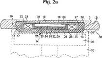
図2aは、図1の金属ケース1のバックカバー3の領域の拡大断面図であり、モジュール14の第1実施例を表す。このモジュール14は、バックカバーのキャビティ13内に永続的に挿入される。 FIG. 2 a is an enlarged cross-sectional view of the region of the
この実施例において、モジュール14は、ベース15を有する。このベース15の上に、データ通信用のアンテナとして機能するコイル23と、このコイル23に接続された集積回路(チップ)24とを有する。ベースは、金属製要素で、磁束を通し、それが金属ケースのバックカバー3のキャビティ13内に搭載された時には、モジュールのコイル23を磁気的に絶縁する。ベース15は、ドームの形態をしており、平坦なボトム16と、両側でコイルを包囲する円筒状の側壁27とを有する。ドーム形状のベース15は、前記キャビティ13内に搭載されるが、これは、平坦なボトム16が、キャビティ13の底部とベース上に搭載されたコイル23との間に配置されるよう行われる。ベースのボトム16は、キャビティ13の底部と接触することができる。 In this embodiment, the
カバー28は、底部と円筒状の側壁17とを含み、ベース15をカバーするよう具備され、コイル23とベース15のボトム16に固定された集積回路(チップ)24とを包囲する。このベースは、カバー内に特にボンディングにより固定される、あるいはカバーの側壁17の内側表面とベースの側壁27の外側表面との間の摩擦力により機械的に保持される。電子モジュールが前記キャビティ13内に搭載されているときには、カバー28のベースの一部は、金属ケース1のバックカバー3の外側フェース33から若干突出する。 The
カバー28を形成する材料は、高密度ポリエチレンのようなプラスチック材料、セラミック材料、サファイア等からなる。プラスチック材料は、大衆用と中級用の時計に用いられ、セラミックあるいはサファイアは、高級時計に用いられる。材料がセラミックの場合には、セラミックは、特に審美的効果を求めない場合には、カバーのバックカバーを形成する金属と同一カラーあるいは同一の見栄えを有するよう選択される。 The material forming the
図2aに示すように、カバー28の側壁17の厚さは、その底から上部に向かって若干且つ連続的に増加する。かくして、側壁17の外側表面18は、キャビティ13の内壁19と共働可能なような特定の形状をし、内壁19は相補的な形状を有し、ワシあるいはハトの尾のような組み立て手段を形成する。 As shown in FIG. 2a, the thickness of the
さらに、カバーの側壁17の外側エッジ20と、キャビティ13の内壁19のエッジ21は丸められて、モジュール14をキャビティ内に導入するのを容易にしている。 In addition, the
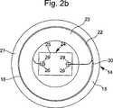
図2bは、図2aのモジュール14の底面図であり、接着充填材料と保護カバーとを省いたものである。 FIG. 2b is a bottom view of the
図2aと図2bとを参照すると、ベース15の側壁27は、完全に円筒状の内側表面22を有する。この内側表面22が、環状具体的には円筒状で且つ平坦な自己支持型のコイル23を包囲する。このコイルは、連続的且つ同軸の巻回の複数の層から公知の方法で形成され(図示せず)、例えば非常に細い金属ワイヤ、好ましくは銅製のワイヤから形成される。このコイルワイヤは、シース、即ち絶縁性の溶融材料(加熱時に一部溶解している)により包囲されている。かくして、ワイヤの巻回を包囲するシースの全ての部分が、コイルが冷却される時に、互いに溶着される。 Referring to FIGS. 2 a and 2 b, the
コイル23そのものが集積回路(チップ)24を包囲する。ICチップ24は、コイルよりも小さい平行なパイプ形状の矩形形態である。集積回路(チップ)24は、その前表面25上に、2個の接続端子すなわちバンプ26を有する。このバンプ26の上に、コイル23の金属ワイヤの2個の端部29が熱圧着あるいは導電性接着剤によりボンディング即ち固定される。 The
図2a、2bに示すように、集積回路(チップ)24の2個のバンプ26は、集積回路(チップ)24の長さ方向に互いに向かい合うように配置される。しかしチップの前面上の異なった場所に配置することも可能である。例えば並べて配置することも可能である。 As shown in FIGS. 2 a and 2 b, the two
この第1実施例においては、コイル23と集積回路(チップ)24は、直接ベース15のボトム16の内側フェース30上に接着材料31の薄いフィルムの手段により固着される。コイルの内側でチップにより残されたスペースは、接着性且つ絶縁性のある熱硬化性材料32、例えばエポキシレジンで充填される。コイル23のワイヤの端部29と、それをバンプ26に固定する手段とは、モジュール14の保護カバー28によりカバーされてはいないが、それらは熱硬化性材料32により保護される。さらに、熱硬化性材料32は、好ましくは不透明で、チップを組み込む前に光が当たらないようにしている。 In this first embodiment, the
金属ケース1のバックカバー3は、磁性材料(例えばスチールあるいはアルミ)製であるために、金属製のベース15は、時計ケースのバックカバー3とコイル23との間の磁気シールドとして機能する。かくして、電子モジュールの磁束は、コイルが読み出し/書き込み装置との間で信号を送受信する時に、大幅に減衰する。さらに、本発明によりベース用に選択された材料故に、データを読み出したり書き込んだりする最大距離は、絶縁性ベースの場合の距離よりも大きくなる。この距離は、モジュールが金属ケースのキャビティ内に配置された時には、8mm以上である。この距離は、送信器とそのアンテナにも依存する。 Since the
図2aに示すように、モジュール14は、金属ケース1のバックカバー3の外側フェース33から若干突出して、ボス34を形成し、このボス34に、読み出し/書き込み装置のヘッド35が配置される。この装置のヘッド35は、図2aでは一部点線で表されている。このヘッド35は、アンテナとしても機能するコイル36を有するが、凹部35’を有し、その形状と寸法はボス34のそれに対応している。ヘッド35は、インターフェースを介して時計のモジュールのメモリと通信するよう設計された装置に接続されている。この装置は、固定型あるいは可動型のパソコン(PC)である。 As shown in FIG. 2 a, the
明らかに、モジュールのボス34により、時計は、ボスの形状と寸法に対応する凹部を有するサポート部材上に同様に配置できる。 Obviously, the
さらにまた、モジュールが金属ケース1のバックカバーから突出している時には、その外側エッジは、好ましくは丸められて、ボス34が時計を装着する人に不快感を与えないようにしている。しかし丸めた部分の代わりに角を落とすだけでもよい。 Furthermore, when the module protrudes from the back cover of the metal case 1, its outer edge is preferably rounded so that the
モジュール14のコイル23により送受信されるブロードキャスト波(信号)は、金属ケース1のバックカバー3の厚さをもはや全部貫通せず、遙かに薄いカバー28の底部分のみを貫通するだけである。かくして、これらの波(信号)は、電子モジュールがケースの底部で内側に配置された公知の時計の場合よりも、その減衰と歪みは遙かに小さい。 Broadcast waves (signals) transmitted and received by the
磁気シールドとして機能するために、非常に高い透磁率の材料を使用する必要がある。そのために、ベースに用いられる材料は、フェライト、又はニッケル、鉄、銅とモリブデンの合金から形成される。好ましくは、この合金は、70−80%のニッケルと10−20%の鉄からなる。Mumetal(登録商標)として公知の材料も使用することができる。 In order to function as a magnetic shield, it is necessary to use a material with very high permeability. For this purpose, the material used for the base is made of ferrite or an alloy of nickel, iron, copper and molybdenum. Preferably, the alloy consists of 70-80% nickel and 10-20% iron. A material known as Mumetal (R) can also be used.
ベース材料は、Sulem(登録商標)として公知の純軟鉄(pure soft iron)から形成することもできる。 The base material can also be formed from pure soft iron, known as Sulem®.
これらのタイプの材料がベース用に用いられると、読み出し/書き込み装置とモジュールとの間の距離を、ICチップ・メモリからのデータの読み出しと書き込み動作に対して、増加させることができる。 When these types of materials are used for the base, the distance between the read / write device and the module can be increased for data read and write operations from the IC chip memory.
以下に示す表においては、読み出し/書き込み装置と電子モジュール(TAG)との最大距離と、データの読み出し/書き込みを行う際の、時計ケース(バックカバー)材料とベース材料との関係を次に示す。
バックカバー 絶縁材料製 スチール製 アルミ製
絶縁性ベース 9mm 6.5mm 1.5mm
Mumetalベース 16mm 9.7mm 9.7mm
Sulemベース 13mm 8.5mm 8 mmIn the table shown below, the maximum distance between the reading / writing device and the electronic module (TAG) and the relationship between the watch case (back cover) material and the base material when reading / writing data are shown below. .
Back cover Insulating material Steel Aluminum
Insulating base 9mm 6.5mm 1.5mm
Mumetal base 16mm 9.7mm 9.7mm
Sulem base 13mm 8.5mm 8mm
上記の表から分かることは、高い透磁率材料製のベースでは、電子モジュールがバックカバーのどこに配置されていようとも、データの読み出しと書き込みの最大距離は、8mm以上である。時計がラッピング・ケースに配置された場合でも、データは、このラッピングケースを介して読み出しおよび書き込みが可能であることを意味する。 As can be seen from the above table, in a base made of a high magnetic permeability material, the maximum distance between reading and writing data is 8 mm or more, no matter where the electronic module is placed on the back cover. Even if the watch is placed in a wrapping case, it means that data can be read and written through this wrapping case.
集積回路(チップ)24は、データを記憶するための1つあるいは複数の種類のメモリを含む。それらは、読み出しのみのデータを記憶するための読み出し専用メモリと、データの削除/変更/追加が可能なメモリである。 The integrated circuit (chip) 24 includes one or more types of memory for storing data. They are a read-only memory for storing read-only data and a memory capable of deleting / changing / adding data.
このことは、電子モジュールが、時計そのもの、より具体的には、その製造業者、購入者、「補修マニュアル」(自動車のそれに類似する)でそれを個人用に改善するようなデータを電子モジュールが記憶できるようなアプリケーションにも、当てはまる。本発明の装置が販売店でも用いられることもある。かくして時計が、検査、修理、単なるバッテリー交換(時計が電子機械式あるいは電子型の場合)の時には、時計の製造業者の作業を容易にする。 This means that the electronic module provides data that the watch itself, and more specifically, its manufacturer, purchaser, and “repair manual” (similar to that of a car) can improve it for personal use. This also applies to applications that can be remembered. The apparatus of the present invention may also be used at a store. Thus, when the watch is inspected, repaired, or simply replaced by a battery (if the watch is electromechanical or electronic), it facilitates the work of the watch manufacturer.
中級から上級にかけての時計の場合、電子モジュールに登録されたデータは、例えば4つのカテゴリーに分けられる。第1カテゴリーは、販売された時計の商標あるいはモデルと、データと、小売業者に時計が渡された発送元の住所とに関する。第2のカテゴリーは、特に時計のムーブメントの製造工場に関する。第3のカテゴリーは、ポイント・オブ・セールス(point of sales)の参照用であり、最後の第4のカテゴリーは、クライアントサービスに関し、例えば、セールスマン又は小売業者が時計に対して行った様々な操作に関する。 In the case of watches from intermediate to advanced, the data registered in the electronic module is divided into, for example, four categories. The first category relates to the trademark or model of the watch sold, the data, and the address from which the watch was delivered to the retailer. The second category relates in particular to the watch movement manufacturing plant. The third category is for point of sales reference and the final fourth category relates to client services, eg various salesmen or retailers performed on watches. Regarding operation.
これらのデータのあるものは、読み出し専用のROMに記憶することもできる。これは、例えば第1と第2のカテゴリーに対して当てはまる。 Some of these data can also be stored in a read-only ROM. This is the case for the first and second categories, for example.
他の2つのカテゴリーのデータは、いくつかのダイナミックメモリ、例えばRAM型、EPROM型、EEPROM型で、削除、変更、書き込みされるものである。 The other two categories of data are deleted, modified, and written in some dynamic memories, such as RAM, EPROM, and EEPROM types.
あらゆる場合において、リーダーのヘッドあるいはサポートのコイルは、適宜のインターフェースを介して固定型あるいは可動型のコンピュータに接続され、これにより、モジュールのメモリ内に含まれているデータを読み出し可能にし、可能ならば、データの一部を削除、変更、書き込みも可能とする。 In all cases, the reader's head or support coil is connected to a fixed or mobile computer via a suitable interface so that the data contained in the module's memory can be read, if possible. For example, a part of data can be deleted, changed, and written.
その後、データは、保護されたインターネット・サイト上、あるいは時計に関連する全ての人にアクセス可能なインターネット・ループ上にアップロードされる。 The data is then uploaded on a protected internet site or on an internet loop accessible to everyone associated with the watch.
図3は、図2aに類似する図であるが、本発明による時計の電子モジュールの第2実施例を示す。同図において、同一の要素は同一の参照番号を付し、新たな部品のみに新たな番号を付す。 FIG. 3 is a view similar to FIG. 2a, but showing a second embodiment of the electronic module of the watch according to the invention. In the figure, the same elements are given the same reference numbers, and only new parts are given new numbers.
図2aの第2実施例との相違点の1つは、図3の第2実施例では、コイル23と集積回路(チップ)24は、ベース15のボトム16の内側フェース30上に直接取り付けられておらず、プリント基板38上に搭載されている点である。この基板38は、モジュール14のベース15のボトム16に結合/搭載されるか、単にベースの内側に搭載される。 One difference from the second embodiment of FIG. 2 a is that in the second embodiment of FIG. 3, the
他の相違点は、図3の第2実施例では、コイル23のワイヤの端部は、集積回路(チップ)24のバンプ26のコイルに直接接続されておらず、プリント基板38の基板上に形成されたバンプ40を介して接続されている点である。より具体的には、端部29の各端部は、熱圧縮による結合あるいは固定、あるいはバンプ40の上の導電性接着剤の手段により結合される。そしてこのバンプ40が集積回路(チップ)24のバンプ26に導電性ワイヤ41を介して接続される。 Another difference is that, in the second embodiment of FIG. 3, the end of the wire of the
従って、コイル23と集積回路(チップ)24は、従来の自動ワイヤ・ボンディング方法を用いて、電気的に結合される。 Accordingly, the
図4に示す第3実施例においては、プリント基板38の側壁17の外側表面18と、時計ケースのバックカバー3のキャビティ13の内壁19とは、両方とも円筒形状である。モジュール14は、キャビティの内側に、組み込みあるいはボンディングにより、固定される。さらに、カバー28の側壁17の外側エッジは、図2a、2bの第1実施例のようには丸められずに、角に傾斜がつけられている。 In the third embodiment shown in FIG. 4, the
この第3実施例においては、ベース15は剛性プレートであり、このプレートがコイル23と集積回路(チップ)24を搭載する。ベース15は、カバー28内に挿入されて、コイルとチップとを包囲する。前の実施例と同様に、ベース15はコイルとキャビティ13の底部との間に配置されて、コイルを磁気的にシードする。ベース15は、コイルの表面のみをカバーしてもよいが、これは、ドーム形状のベースよりも効率が悪い。このベース15は、コイル23の外径よりも若干大きな外径を有する。 In this third embodiment, the
この実施例が適しているのは、ケースのバックカバー3と又はモジュール14のカバー28が機械加工あるいは成型することが困難な硬い材料から形成されている場合である。 This embodiment is suitable when the
さらにまた、図2a、2bの実施例のように、この第3実施例においては、コイル23の端部29は、集積回路(チップ)24のバンプ26の上に直接固定される。しかし、このワイヤ端部とバンプ26とは、図3の実施例と同様な方法で接続可能である。 Furthermore, as in the embodiment of FIGS. 2 a and 2 b, in this third embodiment, the
図には示していない他の実施例では、モジュール14は、ケースのバックカバー3のキャビティ13内にクリッピングにより固定される。モジュールのカバー28は、その底部の側上に外側周辺のノッチを有し、その中に、バックカバー3の内側端部が係合する。モジュールを固定するこの方法は、ボンディングと組み込み設定が不可能な場合、用いることができる。 In another embodiment not shown in the figure, the
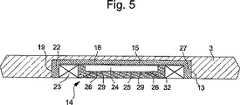
図5に示す電子モジュールの第4実施例においては、磁気シールド用のドーム形状の金属ベース15は、図2a、3に示すように、保護カバーで覆われていない。前記モジュールは、集積回路(チップ)24のカプセル化レジンである熱硬化性材料32とコイル23のワイヤの絶縁により、機械的損傷に対してのみ保護される。しかし、前述した実施例とは異なり、モジュール14の一部は、ベース15に対し相補形状のキャビティ13内に導入され、キャビティ13の外側に突出しない。モジュール14は、ケースのバックカバーのキャビティ13内に組み込み設定あるはボンディングされる。 In the fourth embodiment of the electronic module shown in FIG. 5, the dome-shaped
この第4の実施例においては、ワイヤコイルの端部と集積回路チップとバンプとの接合に関する前述した説明も有効である。 In the fourth embodiment, the above description regarding the bonding of the end of the wire coil, the integrated circuit chip and the bump is also effective.
しかし、コイルワイヤの端部をICチップのバンプに接合する代わりに、この接続は、テープ自動ボンディング(tape aoutomatic bonding)、すなわちTABを用いて得ることもできる。これに関しては、特許文献1を参照のこと。この方法は、腕時計のような金属ケース付き時計に適合したモジュールへも適用可能である。 However, instead of joining the ends of the coil wires to the bumps of the IC chip, this connection can also be obtained using tape aoutomatic bonding, or TAB. For this, see US Pat. This method can also be applied to a module suitable for a watch with a metal case such as a wristwatch.
図6a、6bは、合金製のバー(帯)50のみを示す。このバー50は、容易に機械加工あるいは打ち抜きで形成できる。その結果、電子モジュール構成要素の組み立てが自動化できる。このバー50は、純軟鉄(pure soft iron)あるいはMumetal(登録商標)の合金から形成できる。この種の金属材料では、バー内にドーム形状でいくつかのベース15を容易に形成できる。各ベースは、3個のブリッジ51によりバーの残りの部分に保持される。 6a and 6b show only an
電子モジュール製造ステップにおいて、コイル23と集積回路(チップ)24は、各ドームであるベース15に固定される。その後、接続ワイヤがICチップの接触端子をコイルの端部に接続する。レジンが、その後チップ上に塗布され、コイルとICチップとの間の空間を充填する。全ての電子モジュールがバー50で形成されると、バー50から連続して切り離される。各ベースは、その後、保護カバーにより覆われ、その後モジュールが時計ケースの底部のキャビティ内に導入される。これら全ての操作は自動的に行われて、電子モジュールを具備する時計の製造時間を短縮する。 In the electronic module manufacturing step, the
上記した説明から金属ケースを具備する時計あるいは電子モジュールを具備する時計のさまざまな変形例が本発明の範囲を逸脱することなく、当業者は考え得る。電子モジュールは、その全体を、突起部分を有さずに、時計の外部キャビティ内に収納することも可能であり、読み出しヘッド用の保持装置を具備することも可能である。さらにまた、これらの実施例およびその変形例においては、電子モジュールは、キャビティ内に永久に固定される。しかし、金属ベース用の保護カバーを具備したモジュールを形成するることも、キャビティの内壁と共働するような側壁を具備することも可能であり、これにより、モジュールを取り外したり交換できるようになる。モジュールは、ネジ留めあるいはバヨネット系で固定することもできる。 From the above description, various modifications of a timepiece having a metal case or a timepiece having an electronic module can be considered by those skilled in the art without departing from the scope of the present invention. The entire electronic module can be accommodated in the external cavity of the watch without having a protruding portion, and a holding device for the read head can be provided. Furthermore, in these embodiments and variations thereof, the electronic module is permanently secured within the cavity. However, it is possible to form a module with a protective cover for the metal base or to have a side wall that cooperates with the inner wall of the cavity, so that the module can be removed and replaced. . Modules can also be fixed with screws or bayonet systems.
コイルとICチップは、金属ベース上に搭載する前に、保護カバーに固定することもできる。コイルは、円形リングとは異なる形状を採ることもできる。例えば、矩形あるいはICチップの周囲のループの一部でもよい。 The coil and the IC chip can be fixed to the protective cover before being mounted on the metal base. The coil may take a different shape than the circular ring. For example, it may be a rectangle or a part of a loop around the IC chip.
ベースはまた、フーコー電流(Foucault current)による干渉をさけるために、直径方向のスロットを有してもよい。 The base may also have a diametrical slot to avoid interference due to Foucault current.
以上の説明は、本発明の一実施例に関するもので、この技術分野の当業者であれば、本発明の種々の変形例を考え得るが、それらはいずれも本発明の技術的範囲に包含される。特許請求の範囲の構成要素の後に記載した括弧内の番号は、図面の部品番号に対応し、発明の容易なる理解の為に付したものであり、発明を限定的に解釈するために用いてはならない。また、同一番号でも明細書と特許請求の範囲の部品名は必ずしも同一ではない。これは上記した理由による。 The above description relates to one embodiment of the present invention, and those skilled in the art can consider various modifications of the present invention, all of which are included in the technical scope of the present invention. The The numbers in parentheses described after the constituent elements of the claims correspond to the part numbers in the drawings, are attached for easy understanding of the invention, and are used for limiting the invention. Must not. In addition, the part numbers in the description and the claims are not necessarily the same even with the same number. This is for the reason described above.
1 金属ケース
2 金属製中間部分ベゼル
3 バックカバー
4 ガラス
5 封止ガスケット
6 ムーブメント
7 文字盤
8 分針
9 時針
10 ステム
11 クラウン
12 環状ガスケット
13 キャビティ
14 モジュール
15 ベース
16 平坦ボトム
17 側壁
18 外側表面
19 内壁
20 外側エッジ
21 エッジ
22 内側表面
23 コイル
24 集積回路(チップ)
25 前表面
26 バンプ
27 則壁
28 カバー
29 端部
30 内側フェース
31 接着材料
32 熱硬化性材料
33 外側フェース
34 ボス
35 ヘッド
35’ 凹部
36 コイル
38 プリント基板
40 バンプ
41 導電性ワイヤ
50 バー
51 ブリッジ
DESCRIPTION OF SYMBOLS 1 Metal case 2 Metal
25
Claims (13)
Translated fromJapanese前記電子モジュール(14)は、ベース(15)を有し、
前記ベース(15)の内側に、少なくとも2個のバンプ(26)を有する集積回路チップ(24)と送受信アンテナとして機能するコイル(23)とが搭載され、
前記電子モジュール(14)は、前記ベース(15)の外側を前記時計のバックカバーに形成されたキャビティ(13)の底に向けた状態で、前記キャビティ(13)内に配置され、
前記キャビティ(13)は、前記電子モジュール(14)に対して相補的形状をしており、
前記電子モジュール(14)は、時計の外部に配置される読み出し/書き込み装置(35,36)とブロードキャスト信号を介して通信可能であり、
前記コイル(23)は、前記集積回路チップのバンプにそれぞれ接続される2個の端部(29)を有する導電性ワイヤにより形成され、
前記コイル(23)は、前記集積回路チップ(24)が配置される空間を包囲し、
前記ベース(14)は、金属製であり、その結果、前記読み出し/書き込み装置(35,36)と前記電子モジュールとの間のデータ通信中に、前記電子モジュール(14)のコイル(23)を前記金属製ケースから磁気的に絶縁し、
前記電子モジュール(14)と前記電子モジュールを収納するキャビティ(13)とが、前記読み出し/書き込み装置(35,36)の相補形状をしたヘッド(35)を迅速かつ正確に配置する手段を形成する
ことを特徴とする金属製ケースを具備する時計。In a watch comprising a metal case with anelectronic module (14) for recording data,
Theelectronic module (14) has abase (15),
Inside the base (15), an integrated circuit chip (24) having at least two bumps (26) and a coil (23) functioning as a transmission / reception antenna are mounted,
The electronic module (14) isdisposed in the cavity (13) with the outside of the base (15) facing the bottom of the cavity (13) formed in the back cover of the watch ,
The cavity (13) has a complementary shape to the electronic module (14),
Theelectronic module (14) can communicatewith a read / write device (35, 36)arranged outside thewatch via a broadcast signal,
The coil (23) is formed of a conductive wire having two ends (29) connected to the bumps of the integrated circuit chip,
The coil (23) surrounds a space in which the integrated circuit chip (24) is disposed,
The base (14) ismade of metal, so that the coil (23) of the electronic module (14) is connected during data communication between the read / write device (35, 36) and the electronic module. Magnetically insulated from the metal case,
Theelectronic module (14) and the cavity (13) for housing theelectronic moduleform a meansfor quicklyand accurately placing the complementary head (35) of the read / write device (35, 36). A watch having a metal case.
前記合金は、70−80%のニッケルと10−20%の鉄を含有する
ことを特徴とする請求項1記載の時計。The base (15) of the electronic module (14) is made of pure iron or a material containing nickel, iron, copper, molybdenum, alloy,
2. A timepiece according to claim 1, wherein the alloy contains 70-80% nickel and 10-20% iron.
ことを特徴とする請求項1記載の時計。The said cavity (13) and the said electronic module (14) are cylindrical shape, and are arrange | positioned in the center of the back cover (3) of the said metal case (1). Clock.
前記平坦な底部の内側表面から計った側壁(27)の高さは、前記コイルまたは集積回路チップの厚さ以上であり、
前記ベース(15)は、前記キャビティの内側表面とコイルとの間で、時計の外部表面のキャビティ(13)内に収納される
ことを特徴とする請求項1−4のいずれかに記載の時計。The base (15) has a dome shape, a flat bottom (16) on which the annular coil (23) and an integrated circuit chip (24) are disposed, and a side wall (27) surrounding the coil. And
The height of the side wall (27) measured from the inner surface of the flat bottom is equal to or greater than the thickness of the coil or integrated circuit chip;
5. A timepiece according to claim 1, wherein the base (15) is housed in a cavity (13) on the outer surface of the timepiece between the inner surface of the cavity and the coil. .
前記保護カバー(28)は、前記底部(16)の上に配置されて、前記コイルと集積回路チップとを、前記ベース(15)と共に包囲し、
前記保護カバー(28)は、プラスチック、セラミック材料あるいはサファイア製であり、
前記保護カバー(28)の側壁(17)は、前記キャビティの内側に大部分が固定され、
前記保護カバー(28)の底は、前記キャビティの外側に一部が突出し、
前記電子モジュール(14)は、前記保護カバー(28)内に設定することにより、接着により、あるいはクリッピングにより、前記キャビティ(13)内に固定される
ことを特徴とする請求項1記載の時計。The electronic module has a protective cover (28) having a bottom and an annular side wall (17);
The protective cover (28) is disposed on the bottom (16) and surrounds the coil and the integrated circuit chiptogether with the base (15);
The protective cover (28) is made of plastic, ceramic material or sapphire,
The side wall (17) of the protective cover (28) is mostly fixed inside the cavity,
The bottom of the protective cover (28) partially protrudes outside the cavity;
The timepiece according to claim 1, wherein the electronic module (14) is fixed in the cavity (13) by being set in the protective cover (28), by adhesion or by clipping.
ことを特徴とする請求項5記載の時計。The thickness of the side wall (17) of the cover increases continuously from the bottom to the top, the outer surface (18) cooperates with the complementary inner wall (19) of the cavity (13), and the electrons 6. Timepiece according to claim 5, characterized in that dovetail-shaped assembly means are formed between the module (14) and the cavity of the watch surface.
前記キャビティ(13)は、円筒形状の内壁(19)を有する
ことを特徴とする請求項5記載の時計。The side wall (17) of the protective cover (28) has a cylindrical outer surface (18);
The timepiece according to claim 5, wherein the cavity (13) has a cylindrical inner wall (19).
前記剛性プレート上に前記コイル(23)と集積回路チップ(24)が固定され、
前記ベース(15)は、外部の時計表面とコイルとの間に配置される
ことを特徴とする請求項1−3、5のいずれかに記載の時計。The base (15) is formed by an annular rigid plate;
The coil (23) and the integrated circuit chip (24) are fixed on the rigid plate,
The timepiece according to claim 1, wherein the base is arranged between an external timepiece surface and a coil.
前記コイルのワイヤ端部(29)は、導電性材料手段により集積回路チップの前記バンプ(26)に直接取り付けられる
ことを特徴とする請求項1記載の時計。The coil (23) and the integrated circuit chip (24) are directly fixed by bonding on the base (15),
A timepiece according to claim 1, characterized in that the wire end (29) of the coil is directly attached to the bump (26) of the integrated circuit chip by means of conductive material.
前記プリント基板(38)は、前記コイルと前記チップとの間に配置された2個の接続用のバンプ(40)を有し、
前記バンプ(40)の上に、前記コイルのワイヤ端部が取り付けられ、
前記2個の導電性ワイヤ(41)の2つの端部あるいは他の端部は、前記チップのバンプ(26)上に取り付けられる
ことを特徴とする請求項1記載の時計。The coil (23) and the integrated circuit chip (24) are fixed on a printed circuit board (38),
The printed circuit board (38) has two connection bumps (40) arranged between the coil and the chip,
On the bump (40), the wire end of the coil is attached,
A timepiece according to claim 1, characterized in that two or other ends of the two conductive wires (41) are mounted on the bumps (26) of the chip.
ことを特徴とする請求項1記載の時計。The electronic module (14) housed in the cavity partially protrudes outside the back cover (3) of the metal case (1), and is a head complementary to the read / write device (35, 36). A timepiece according to claim 1, characterized in that it forms means for quickly and accurately arranging (35).
前記電子モジュール(14)は、ベース(15)を有し、
前記ベース(15)の上に、少なくとも2個のバンプ(26)を有する集積回路チップ(24)と、送受信用アンテナとして機能するコイル(23)とが搭載され、
前記コイル(23)は、導電性ワイヤにより形成され、この導電性ワイヤの2個の端部はそれぞれ、前記集積回路チップの前記バンプにそれぞれ接続され、
前記コイル(23)は、前記集積回路チップが配置された空間を包囲し、
前記ベース(15)は、磁気シールドとして機能する磁束を誘導する金属製要素である
ことを特徴とする電子モジュール。Electronic module (14) used for a timepiece according to claim 1-11,
Theelectronic module (14) has a base (15),
On the base (15), an integrated circuit chip (24) having at least two bumps (26) and a coil (23) functioning as a transmission / reception antenna are mounted.
The coil (23) is formed of a conductive wire, and two ends of the conductive wire are respectively connected to the bumps of the integrated circuit chip,
The coil (23) surrounds a space in which the integrated circuit chip is disposed,
The electronic module according to claim 1, wherein the base (15) is a metal element that induces a magnetic flux that functions as a magnetic shield.
保護カバー(28)と前記ベース(15)とにより、コイルと集積回路チップとを包囲し、
前記保護カバー(28)は、プラスチック材料、セラミック材料あるいはサファイア製である
ことを特徴とする請求項12記載の電子モジュール。A protective cover (28) disposed on the base;
The protective cover (28) and said base (15), surrounds thecoils and the integrated circuit chip,
13. The electronic module according to claim 12, wherein the protective cover is made of a plastic material, a ceramic material or sapphire.
Applications Claiming Priority (3)
| Application Number | Priority Date | Filing Date | Title |
|---|---|---|---|
| EP03019951AEP1513032A1 (en) | 2003-09-02 | 2003-09-02 | Object with a metallic case comprising an electronic module suitable for the memorization of information, and electronic module compatible with such an object |
| EP03019951.7 | 2003-09-02 | ||
| PCT/EP2004/009442WO2005024528A1 (en) | 2003-09-02 | 2004-08-24 | Metal case watch provided with an electonic module for reading in information and an electronic module for such a watch |
Publications (2)
| Publication Number | Publication Date |
|---|---|
| JP2007504437A JP2007504437A (en) | 2007-03-01 |
| JP4722045B2true JP4722045B2 (en) | 2011-07-13 |
Family
ID=34130112
Family Applications (1)
| Application Number | Title | Priority Date | Filing Date |
|---|---|---|---|
| JP2006524318AExpired - LifetimeJP4722045B2 (en) | 2003-09-02 | 2004-08-24 | Timepiece with metal case having an electronic module for storing data and electronic module for such a watch |
Country Status (9)
| Country | Link |
|---|---|
| US (1) | US7385874B2 (en) |
| EP (2) | EP1513032A1 (en) |
| JP (1) | JP4722045B2 (en) |
| KR (1) | KR101047217B1 (en) |
| CN (1) | CN100541357C (en) |
| AT (1) | ATE495482T1 (en) |
| CA (1) | CA2537187C (en) |
| DE (1) | DE602004031025D1 (en) |
| WO (1) | WO2005024528A1 (en) |
Families Citing this family (59)
| Publication number | Priority date | Publication date | Assignee | Title |
|---|---|---|---|---|
| US7898642B2 (en) | 2004-04-14 | 2011-03-01 | Asml Netherlands B.V. | Lithographic apparatus and device manufacturing method |
| EP1597636B1 (en)* | 2004-04-24 | 2007-01-03 | Winwatch SA | Method for integrating at least one electronic module in or on the glass of a watch |
| DE102006019925B4 (en)* | 2006-04-28 | 2010-09-16 | Infineon Technologies Ag | Chip module, smart card and method of making this |
| US20100004518A1 (en) | 2008-07-03 | 2010-01-07 | Masimo Laboratories, Inc. | Heat sink for noninvasive medical sensor |
| JP2011097431A (en)* | 2009-10-30 | 2011-05-12 | Seiko Epson Corp | Arm-mounted electronic apparatus |
| WO2011053182A1 (en)* | 2009-11-02 | 2011-05-05 | Leontiev Vladimir Vasilievich | Information storage and processing device (ispd) |
| CN102858102A (en)* | 2011-06-28 | 2013-01-02 | 鸿富锦精密工业(深圳)有限公司 | Electronic equipment shell and manufacturing method thereof |
| JP2014027036A (en)* | 2012-07-25 | 2014-02-06 | Alps Electric Co Ltd | Electronic circuit module |
| JP5678972B2 (en)* | 2013-02-15 | 2015-03-04 | カシオ計算機株式会社 | Electronics |
| US9753436B2 (en) | 2013-06-11 | 2017-09-05 | Apple Inc. | Rotary input mechanism for an electronic device |
| EP3014400B1 (en) | 2013-08-09 | 2020-06-03 | Apple Inc. | Tactile switch for an electronic device |
| JP5674895B1 (en)* | 2013-10-29 | 2015-02-25 | 京セラ株式会社 | Electronics |
| WO2015088492A1 (en) | 2013-12-10 | 2015-06-18 | Apple Inc. | Input friction mechanism for rotary inputs of electronic devices |
| USD727194S1 (en) | 2014-01-21 | 2015-04-21 | Wimo Labs LLC | Bracelet |
| US10048802B2 (en) | 2014-02-12 | 2018-08-14 | Apple Inc. | Rejection of false turns of rotary inputs for electronic devices |
| US9583256B2 (en)* | 2014-06-13 | 2017-02-28 | Verily Life Sciences Llc | Three-dimensional wireless charging coil |
| US10190891B1 (en) | 2014-07-16 | 2019-01-29 | Apple Inc. | Optical encoder for detecting rotational and axial movement |
| KR20250021617A (en) | 2014-09-02 | 2025-02-13 | 애플 인크. | Wearable electronic device |
| US10145712B2 (en) | 2014-09-09 | 2018-12-04 | Apple Inc. | Optical encoder including diffuser members |
| US9829350B2 (en)* | 2014-09-09 | 2017-11-28 | Apple Inc. | Magnetically coupled optical encoder |
| US9450298B2 (en) | 2014-10-01 | 2016-09-20 | Salutron, Inc. | User-wearable devices with primary and secondary radiator antennas |
| WO2016141228A1 (en) | 2015-03-05 | 2016-09-09 | Apple Inc. | Optical encoder with direction-dependent optical properties |
| US9651405B1 (en) | 2015-03-06 | 2017-05-16 | Apple Inc. | Dynamic adjustment of a sampling rate for an optical encoder |
| EP3251139B1 (en) | 2015-03-08 | 2021-04-28 | Apple Inc. | Compressible seal for rotatable and translatable input mechanisms |
| US10018966B2 (en) | 2015-04-24 | 2018-07-10 | Apple Inc. | Cover member for an input mechanism of an electronic device |
| WO2017016872A1 (en)* | 2015-07-24 | 2017-02-02 | Sevenfriday AG | Wrist watch with data storage and wireless data exchange capability and method to identify such a watch |
| US10503271B2 (en) | 2015-09-30 | 2019-12-10 | Apple Inc. | Proximity detection for an input mechanism of an electronic device |
| CN105554198A (en)* | 2016-02-01 | 2016-05-04 | 广东欧珀移动通信有限公司 | Display device and mobile terminal having same |
| US9891651B2 (en) | 2016-02-27 | 2018-02-13 | Apple Inc. | Rotatable input mechanism having adjustable output |
| US10585480B1 (en) | 2016-05-10 | 2020-03-10 | Apple Inc. | Electronic device with an input device having a haptic engine |
| US10551798B1 (en) | 2016-05-17 | 2020-02-04 | Apple Inc. | Rotatable crown for an electronic device |
| US10061399B2 (en) | 2016-07-15 | 2018-08-28 | Apple Inc. | Capacitive gap sensor ring for an input device |
| US10019097B2 (en) | 2016-07-25 | 2018-07-10 | Apple Inc. | Force-detecting input structure |
| TWI605750B (en)* | 2017-01-19 | 2017-11-11 | 巨擘科技股份有限公司 | Communication device and manufacturing method thereof |
| US10664074B2 (en) | 2017-06-19 | 2020-05-26 | Apple Inc. | Contact-sensitive crown for an electronic watch |
| TWI645688B (en)* | 2017-07-11 | 2018-12-21 | 巨擘科技股份有限公司 | Wearable device and method of operation thereof |
| US10962935B1 (en) | 2017-07-18 | 2021-03-30 | Apple Inc. | Tri-axis force sensor |
| US11054932B2 (en) | 2017-09-06 | 2021-07-06 | Apple Inc. | Electronic device having a touch sensor, force sensor, and haptic actuator in an integrated module |
| US10203662B1 (en) | 2017-09-25 | 2019-02-12 | Apple Inc. | Optical position sensor for a crown |
| CN108594634B (en)* | 2018-04-16 | 2021-07-23 | 广东小天才科技有限公司 | Watch case and telephone watch provided with antenna, and antenna layout method of telephone watch |
| CN108594623B (en)* | 2018-04-16 | 2021-07-23 | 广东小天才科技有限公司 | A metal watch case and its smart wearable device |
| US11360440B2 (en) | 2018-06-25 | 2022-06-14 | Apple Inc. | Crown for an electronic watch |
| US11561515B2 (en) | 2018-08-02 | 2023-01-24 | Apple Inc. | Crown for an electronic watch |
| CN211293787U (en) | 2018-08-24 | 2020-08-18 | 苹果公司 | Electronic watch |
| US12259690B2 (en) | 2018-08-24 | 2025-03-25 | Apple Inc. | Watch crown having a conductive surface |
| US11181863B2 (en) | 2018-08-24 | 2021-11-23 | Apple Inc. | Conductive cap for watch crown |
| US11194298B2 (en) | 2018-08-30 | 2021-12-07 | Apple Inc. | Crown assembly for an electronic watch |
| CN209625187U (en) | 2018-08-30 | 2019-11-12 | 苹果公司 | Electronic Watches and Electronic Devices |
| US10966007B1 (en) | 2018-09-25 | 2021-03-30 | Apple Inc. | Haptic output system |
| CH715678B1 (en) | 2018-12-20 | 2022-09-30 | Boninchi Sa | Communication device comprising a watch equipped with a radiofrequency chip. |
| US11194299B1 (en) | 2019-02-12 | 2021-12-07 | Apple Inc. | Variable frictional feedback device for a digital crown of an electronic watch |
| US10531693B1 (en)* | 2019-02-14 | 2020-01-14 | Glas, Inc. | Vaporization device having remotely controllable operational modes |
| WO2021146333A1 (en) | 2020-01-13 | 2021-07-22 | Masimo Corporation | Wearable device with physiological parameters monitoring |
| US11550268B2 (en) | 2020-06-02 | 2023-01-10 | Apple Inc. | Switch module for electronic crown assembly |
| US11024135B1 (en)* | 2020-06-17 | 2021-06-01 | Apple Inc. | Portable electronic device having a haptic button assembly |
| USD1030514S1 (en) | 2021-04-09 | 2024-06-11 | Google Llc | Watch body |
| EP4370022A1 (en) | 2021-07-13 | 2024-05-22 | Masimo Corporation | Wearable device with physiological parameters monitoring |
| US12092996B2 (en) | 2021-07-16 | 2024-09-17 | Apple Inc. | Laser-based rotation sensor for a crown of an electronic watch |
| US12189347B2 (en) | 2022-06-14 | 2025-01-07 | Apple Inc. | Rotation sensor for a crown of an electronic watch |
Family Cites Families (16)
| Publication number | Priority date | Publication date | Assignee | Title |
|---|---|---|---|---|
| JPH07121315B2 (en)* | 1990-06-22 | 1995-12-25 | ジューキ株式会社 | Needle thread supply device for two-needle sewing machine |
| ATE196813T1 (en)* | 1993-10-08 | 2000-10-15 | Valtac Alex Beaud | STORAGE ARRANGEMENT |
| FR2740664B1 (en)* | 1995-11-06 | 1998-01-23 | Degonda Richard Anton | MODULAR JEWELRY PIECE, ESPECIALLY RING, EARRING, PENDANT OR TIME INSTRUMENT SUCH AS A WATCH |
| DE19613491B4 (en)* | 1996-04-04 | 2005-07-21 | Junghans Uhren Gmbh | Transponder wristwatch |
| CH690525A5 (en)* | 1996-11-22 | 2000-09-29 | Ebauchesfabrik Eta Ag | Timepiece including a receiving antenna and / or transmitting a radio broadcast signal. |
| JP3106206B1 (en)* | 1999-05-27 | 2000-11-06 | 新生化学工業株式会社 | Information storage medium portable device |
| DE19946254A1 (en)* | 1999-09-27 | 2001-04-26 | David Finn | Transponder tag and method of manufacture in which a transponder chip and coil are encased in grout compound on a former to provide a simple and economic production process |
| DE60102577T2 (en)* | 2000-04-18 | 2005-02-03 | Nagraid S.A. | ELECTRONIC LABEL |
| JP3622700B2 (en)* | 2000-09-19 | 2005-02-23 | セイコーエプソン株式会社 | Electronic device and control method of electronic device |
| JP2002290131A (en)* | 2000-12-18 | 2002-10-04 | Mitsubishi Materials Corp | Antenna for transponder |
| TW531976B (en)* | 2001-01-11 | 2003-05-11 | Hanex Co Ltd | Communication apparatus and installing structure, manufacturing method and communication method |
| JP2003035786A (en)* | 2001-07-25 | 2003-02-07 | Mitsubishi Materials Corp | Watch with tag |
| EP1424611A4 (en)* | 2001-09-07 | 2006-08-30 | Seiko Epson Corp | ELECTRONIC CLOCK WITH CONTACTLESS DATA COMMUNICATION FUNCTION AND CONTACTLESS DATA COMMUNICATION SYSTEM |
| DE60223723T2 (en)* | 2001-12-14 | 2008-10-30 | Mbbs S.A. | WATCH HOUSING |
| EP1398676A1 (en)* | 2002-09-10 | 2004-03-17 | The Swatch Group Management Services AG | Timepiece comprising an electronic module suitable to store information and arranged in the case bottom |
| ATE399375T1 (en)* | 2002-10-28 | 2008-07-15 | Eta Sa Mft Horlogere Suisse | PORTABLE ELECTRONIC DEVICE HAVING AN ELECTRICAL CONNECTION IN THE DEVICE HOUSING |
- 2003
- 2003-09-02EPEP03019951Apatent/EP1513032A1/ennot_activeWithdrawn
- 2004
- 2004-08-24JPJP2006524318Apatent/JP4722045B2/ennot_activeExpired - Lifetime
- 2004-08-24CNCNB2004800252469Apatent/CN100541357C/ennot_activeExpired - Lifetime
- 2004-08-24DEDE602004031025Tpatent/DE602004031025D1/ennot_activeExpired - Lifetime
- 2004-08-24USUS10/595,130patent/US7385874B2/ennot_activeExpired - Lifetime
- 2004-08-24EPEP04764420Apatent/EP1660953B1/ennot_activeExpired - Lifetime
- 2004-08-24KRKR1020067004287Apatent/KR101047217B1/ennot_activeExpired - Lifetime
- 2004-08-24ATAT04764420Tpatent/ATE495482T1/ennot_activeIP Right Cessation
- 2004-08-24CACA2537187Apatent/CA2537187C/ennot_activeExpired - Lifetime
- 2004-08-24WOPCT/EP2004/009442patent/WO2005024528A1/enactiveApplication Filing
Also Published As
| Publication number | Publication date |
|---|---|
| EP1660953A1 (en) | 2006-05-31 |
| ATE495482T1 (en) | 2011-01-15 |
| JP2007504437A (en) | 2007-03-01 |
| EP1513032A1 (en) | 2005-03-09 |
| WO2005024528A1 (en) | 2005-03-17 |
| EP1660953B1 (en) | 2011-01-12 |
| CA2537187A1 (en) | 2005-03-17 |
| KR101047217B1 (en) | 2011-07-06 |
| HK1097057A1 (en) | 2007-06-15 |
| US20070297294A1 (en) | 2007-12-27 |
| CN100541357C (en) | 2009-09-16 |
| KR20060123080A (en) | 2006-12-01 |
| CN1846179A (en) | 2006-10-11 |
| DE602004031025D1 (en) | 2011-02-24 |
| CA2537187C (en) | 2014-10-28 |
| US7385874B2 (en) | 2008-06-10 |
Similar Documents
| Publication | Publication Date | Title |
|---|---|---|
| JP4722045B2 (en) | Timepiece with metal case having an electronic module for storing data and electronic module for such a watch | |
| JP4282020B2 (en) | Watch having an electronic module for storing information on the back side of the case | |
| JP3106206B1 (en) | Information storage medium portable device | |
| CA2132784A1 (en) | Memory device | |
| CN112469303A (en) | Metal jewelry with non-contact short-distance wireless communication function and manufacturing method thereof | |
| US4864383A (en) | Method of fabrication of a chip carrier package, a flush-contact chip carrier package and an application to cards containing components | |
| CN100568623C (en) | Antenna device and clock with antenna device | |
| JP2008141387A (en) | ANTENNA DEVICE, ANTENNA DEVICE MANUFACTURING METHOD, AND ELECTRONIC DEVICE | |
| JP5397488B2 (en) | Watches | |
| HK1097057B (en) | Watch with metallic case including an electronic module and electronic module for such a watch | |
| HK1078943B (en) | Watch comprising an electronic information-storage unit in the base of the case thereof | |
| WO2017016872A1 (en) | Wrist watch with data storage and wireless data exchange capability and method to identify such a watch | |
| JP2001272480A (en) | Wrist watch with communication function | |
| JP2008141389A (en) | ANTENNA DEVICE, ANTENNA DEVICE MANUFACTURING METHOD, AND ELECTRONIC DEVICE | |
| CN113948850B (en) | Assembly process method and structure of watch antenna and smart watch | |
| JP5169413B2 (en) | Method for manufacturing antenna | |
| JPH10244792A (en) | Non-contact type ic card | |
| JPH07318668A (en) | Structure of watch with receiving antenna | |
| JPS61248285A (en) | Magnetic bubble memory device | |
| JPH02309659A (en) | Lead frames, integrated circuit devices using the same, and methods of manufacturing them | |
| JP2004096682A (en) | Antenna device |
Legal Events
| Date | Code | Title | Description |
|---|---|---|---|
| A621 | Written request for application examination | Free format text:JAPANESE INTERMEDIATE CODE: A621 Effective date:20070726 | |
| A131 | Notification of reasons for refusal | Free format text:JAPANESE INTERMEDIATE CODE: A131 Effective date:20100826 | |
| A601 | Written request for extension of time | Free format text:JAPANESE INTERMEDIATE CODE: A601 Effective date:20101119 | |
| A602 | Written permission of extension of time | Free format text:JAPANESE INTERMEDIATE CODE: A602 Effective date:20101129 | |
| A521 | Request for written amendment filed | Free format text:JAPANESE INTERMEDIATE CODE: A523 Effective date:20101222 | |
| TRDD | Decision of grant or rejection written | ||
| A01 | Written decision to grant a patent or to grant a registration (utility model) | Free format text:JAPANESE INTERMEDIATE CODE: A01 Effective date:20110323 | |
| A01 | Written decision to grant a patent or to grant a registration (utility model) | Free format text:JAPANESE INTERMEDIATE CODE: A01 | |
| A61 | First payment of annual fees (during grant procedure) | Free format text:JAPANESE INTERMEDIATE CODE: A61 Effective date:20110405 | |
| FPAY | Renewal fee payment (event date is renewal date of database) | Free format text:PAYMENT UNTIL: 20140415 Year of fee payment:3 | |
| R150 | Certificate of patent or registration of utility model | Ref document number:4722045 Country of ref document:JP Free format text:JAPANESE INTERMEDIATE CODE: R150 Free format text:JAPANESE INTERMEDIATE CODE: R150 | |
| R250 | Receipt of annual fees | Free format text:JAPANESE INTERMEDIATE CODE: R250 | |
| R250 | Receipt of annual fees | Free format text:JAPANESE INTERMEDIATE CODE: R250 | |
| R250 | Receipt of annual fees | Free format text:JAPANESE INTERMEDIATE CODE: R250 | |
| R250 | Receipt of annual fees | Free format text:JAPANESE INTERMEDIATE CODE: R250 | |
| R250 | Receipt of annual fees | Free format text:JAPANESE INTERMEDIATE CODE: R250 | |
| R250 | Receipt of annual fees | Free format text:JAPANESE INTERMEDIATE CODE: R250 | |
| R250 | Receipt of annual fees | Free format text:JAPANESE INTERMEDIATE CODE: R250 | |
| R250 | Receipt of annual fees | Free format text:JAPANESE INTERMEDIATE CODE: R250 | |
| R250 | Receipt of annual fees | Free format text:JAPANESE INTERMEDIATE CODE: R250 | |
| R250 | Receipt of annual fees | Free format text:JAPANESE INTERMEDIATE CODE: R250 | |
| R250 | Receipt of annual fees | Free format text:JAPANESE INTERMEDIATE CODE: R250 | |
| EXPY | Cancellation because of completion of term |