JP4719802B2 - Storage management device, storage management method and storage system - Google Patents
Storage management device, storage management method and storage systemDownload PDFInfo
- Publication number
- JP4719802B2 JP4719802B2JP2009055713AJP2009055713AJP4719802B2JP 4719802 B2JP4719802 B2JP 4719802B2JP 2009055713 AJP2009055713 AJP 2009055713AJP 2009055713 AJP2009055713 AJP 2009055713AJP 4719802 B2JP4719802 B2JP 4719802B2
- Authority
- JP
- Japan
- Prior art keywords
- storage
- data
- spare
- group
- buffer
- Prior art date
- Legal status (The legal status is an assumption and is not a legal conclusion. Google has not performed a legal analysis and makes no representation as to the accuracy of the status listed.)
- Expired - Fee Related
Links
Images


Classifications
- G—PHYSICS
- G06—COMPUTING OR CALCULATING; COUNTING
- G06F—ELECTRIC DIGITAL DATA PROCESSING
- G06F11/00—Error detection; Error correction; Monitoring
- G06F11/07—Responding to the occurrence of a fault, e.g. fault tolerance
- G06F11/16—Error detection or correction of the data by redundancy in hardware
- G06F11/20—Error detection or correction of the data by redundancy in hardware using active fault-masking, e.g. by switching out faulty elements or by switching in spare elements
- G06F11/2053—Error detection or correction of the data by redundancy in hardware using active fault-masking, e.g. by switching out faulty elements or by switching in spare elements where persistent mass storage functionality or persistent mass storage control functionality is redundant
- G06F11/2094—Redundant storage or storage space
- G—PHYSICS
- G06—COMPUTING OR CALCULATING; COUNTING
- G06F—ELECTRIC DIGITAL DATA PROCESSING
- G06F11/00—Error detection; Error correction; Monitoring
- G06F11/07—Responding to the occurrence of a fault, e.g. fault tolerance
- G06F11/08—Error detection or correction by redundancy in data representation, e.g. by using checking codes
- G06F11/10—Adding special bits or symbols to the coded information, e.g. parity check, casting out 9's or 11's
- G06F11/1076—Parity data used in redundant arrays of independent storages, e.g. in RAID systems
- G—PHYSICS
- G06—COMPUTING OR CALCULATING; COUNTING
- G06F—ELECTRIC DIGITAL DATA PROCESSING
- G06F11/00—Error detection; Error correction; Monitoring
- G06F11/07—Responding to the occurrence of a fault, e.g. fault tolerance
- G06F11/14—Error detection or correction of the data by redundancy in operation
- G06F11/1402—Saving, restoring, recovering or retrying
- G06F11/1415—Saving, restoring, recovering or retrying at system level
- G06F11/1441—Resetting or repowering
Landscapes
- Engineering & Computer Science (AREA)
- Theoretical Computer Science (AREA)
- Quality & Reliability (AREA)
- Physics & Mathematics (AREA)
- General Engineering & Computer Science (AREA)
- General Physics & Mathematics (AREA)
- Information Retrieval, Db Structures And Fs Structures Therefor (AREA)
- Techniques For Improving Reliability Of Storages (AREA)
Description
Translated fromJapanese本発明は、ストレージデバイスをグループ化し、グループ内のストレージデバイス間でユーザデータの分散や冗長化を行なわせるストレージ管理装置、ストレージ管理方法およびストレージシステムに関する。 The present invention relates to a storage management apparatus, a storage management method, and a storage system that group storage devices and distribute or make user data distributed among the storage devices in the group.
従来、複数のストレージデバイスをグループ化し、グループ内のストレージデバイス間でデータの分散や冗長化を行なうことでストレージシステムの信頼性やアクセス速度を向上する技術が利用されてきた。 Conventionally, a technique for improving the reliability and access speed of a storage system by grouping a plurality of storage devices and distributing and making data redundant among the storage devices in the group has been used.
かかるストレージシステムとして、例えば、ストレージデバイスにハードディスクを用いるRAID(Redundant Arrays of Inexpensive Disks)が知られている。RAIDは、複数台のハードディスクを組み合わせることで仮想的な1台のハードディスクとして運用する技術であり、RAID0〜RAID6の7種類のレベルが定義されている。RAID0〜RAID6のうち、特にRAID0、RAID1、RAID5、RAID6がよく利用される。 As such a storage system, for example, RAID (Redundant Arrays of Inexpensive Disks) using a hard disk as a storage device is known. RAID is a technique for operating as a single virtual hard disk by combining a plurality of hard disks, and seven levels of
RAID0は、複数台のハードディスクに、データを分散して読み書きし、高速化したものである。RAID1は、複数台のハードディスクに同時に同じ内容を書き込むミラーリングを行なってデータを冗長化し、耐障害性を向上したものである。RAID5は、複数のハードディスクに誤り訂正符号データと共にデータを分散させて記録することで、耐障害性とアクセス性能を共に向上したものである。RAID6は、RAID5の信頼性を更に向上したものであり、冗長データを2種類作成して2つのディスクに記録することで、2重障害に対応でき、同時に2ドライブが故障しても復元できる。
RAID1、RAID5、RAID6では、一部のハードディスクが故障しても論理ディスクは稼動できる。そして故障が発生した場合、論理ディスクを稼働させたまま故障したハードディスクを取り外して代わりのハードディスクに交換することにより装置を停止することなく運用を続けることができる。装置が稼働中に接続しなおして、即座に利用できるよう設けられた予備用のディスクがスペアディスクである。 In RAID1, RAID5, and RAID6, logical disks can operate even if some hard disks fail. When a failure occurs, the operation can be continued without stopping the apparatus by removing the failed hard disk and replacing it with a replacement hard disk while the logical disk is operating. A spare disk provided so that the apparatus can be reconnected while it is in operation and used immediately is a spare disk.
なお、ストレージシステムが複数のグループを構成し、各グループをそれぞれ仮想的なディスクとして取り扱う場合、スペアディスクはグループ間で共用することができる。 When the storage system forms a plurality of groups and each group is handled as a virtual disk, a spare disk can be shared between the groups.
また、RAIDグループを動作させつつ、新たなディスクを追加して同一のRAIDレベルのままでグループ全体のディスク容量を増加させる構成変更や、RAIDレベルを変更する構成変更を行なう、所謂LDE(Logical Device Expansion)も知られている。 In addition, a so-called LDE (Logical Device) that performs a configuration change to increase the disk capacity of the entire group while adding a new disk while maintaining the RAID level while operating a RAID group, or a configuration change to change the RAID level is performed. Expansion) is also known.
ストレージグループの構成変更を行なう場合、旧構成に基づいて論理ディスクからデータを読み出し、読み出したデータを一時的にバッファ上に格納してから、新構成に基づいて論理ディスクにデータを書き込む。この読み出してから書込みが終了するまでの間に、一時的にバッファ上にしかデータが存在しない状況が発生する。 When changing the configuration of a storage group, data is read from the logical disk based on the old configuration, the read data is temporarily stored in a buffer, and then the data is written to the logical disk based on the new configuration. Between this reading and the end of writing, a situation occurs in which data temporarily exists only on the buffer.
具体的には、バッファから新構成の論理ディスクへの書き込みの処理中には、実際のディスクにどこまで書き込まれたかが不明であるため、書き込み処理対象であるディスク上のデータは信頼できない状態となっている。 Specifically, during the process of writing from the buffer to the newly configured logical disk, it is unclear how much data has been written to the actual disk, so the data on the disk to be written becomes unreliable. Yes.
そのため、バッファとして使用しているメモリの故障や、停電時にバッテリーバックアップが機能しない状態などが発生した場合に、バッファ上のデータが消失する可能性があるという問題点があった。 For this reason, there is a problem in that data in the buffer may be lost when a failure occurs in a memory used as a buffer or when a battery backup does not function during a power failure.
また、従来の技術では、ストレージグループの構成変更を一旦開始すると、処理途中で構成変更を中止し、元の構成に戻すことができなかった。そのため、オペレーションミスやシステム運用条件の変更などで構成変更の取り消しが求められる場合に対応することができないという問題点があった。 Further, in the conventional technique, once the storage group configuration change is started, the configuration change cannot be canceled in the middle of the processing and returned to the original configuration. For this reason, there has been a problem that it is impossible to cope with the case where cancellation of the configuration change is required due to an operation error or a change in system operation conditions.
開示の技術は、上記に鑑みてなされたものであって、構成変更中のデータ消失の防止や、構成変更を中断して元の構成に復旧することができるストレージ管理装置、ストレージ管理方法およびストレージシステムを提供することを目的とする。 The disclosed technology has been made in view of the above, and is a storage management device, a storage management method, and a storage that can prevent data loss during a configuration change and can interrupt the configuration change and restore the original configuration The purpose is to provide a system.
本願の開示するストレージ管理装置、ストレージ管理方法およびストレージシステムは、ストレージデバイスのグループの構成変更を行なう場合に、ストレージデバイスにおける障害発生時に使用するスペアストレージを構成変更用に確保し、グループの構成変更処理にかかるデータを確保したスペアストレージに書き込み、グループの構成変更が中断した場合にはスペアストレージに書き込んだデータを用いてグループの構成変更の継続もしくはグループの変更開始前の状態への復旧を行なう。 The storage management device, the storage management method, and the storage system disclosed in the present application reserve spare storage to be used for a configuration change when a storage device group configuration is changed, and change the group configuration. Write the data required for processing to the spare storage, and if the group configuration change is interrupted, use the data written to the spare storage to continue the group configuration change or restore the state before starting the group change .
本願の開示するストレージ管理装置、ストレージ管理方法およびストレージシステムの一つの態様によれば、構成変更中のデータ消失の防止や、構成変更を中断して元の構成に復旧することができるストレージ管理装置、ストレージ管理方法およびストレージシステムを得ることができるという効果を奏する。 According to one aspect of the storage management device, the storage management method, and the storage system disclosed in the present application, it is possible to prevent data loss during a configuration change and to restore the original configuration by interrupting the configuration change. The storage management method and the storage system can be obtained.
以下に、本願の開示するストレージ管理装置、ストレージ管理方法およびストレージシステムの実施例を図面に基づいて詳細に説明する。なお、この実施例によりこの発明が限定されるものではない。 Hereinafter, embodiments of a storage management device, a storage management method, and a storage system disclosed in the present application will be described in detail with reference to the drawings. Note that the present invention is not limited to the embodiments.
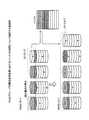
図1は、実施例にかかるストレージシステムの概要構成を示す概要構成図である。図1に示したストレージシステムは、ストレージ管理装置であるストレージコントローラ10,20,30,40を有する。ストレージコントローラ10は、ユーザデータを格納するストレージデバイス、所謂ストレージとして機能するディスクD11〜18と接続している。同様に、ストレージコントローラ20は、ディスクD21〜28と接続し、ストレージコントローラ30は、ディスクD31〜38と接続し、ストレージコントローラ40は、ディスクD41〜48と接続している。 FIG. 1 is a schematic configuration diagram illustrating a schematic configuration of the storage system according to the embodiment. The storage system shown in FIG. 1 has
ストレージコントローラ10は、その内部に主制御部11とメモリ12を有する。さらに主制御部11は、その内部にアクセス処理部13、冗長性復旧処理部14、ディスク管理部15およびRAID構成変更処理部16を有する。主制御部11が有する各処理部は、それぞれワイヤードロジックやPLD(Programmable Logic Device)などで実現してもよいし、主制御部11をCPU(Central Processing Unit)などの演算装置で実現し、各処理をソフトウェアで実現してもよい。 The
アクセス処理部13は、図示しないホスト、ホストからのストレージに対するアクセス要求を処理する。また、ストレージコントローラ10は、配下のディスクD11〜18、および他のストレージコントローラと接続している。アクセス処理部13は、ストレージコントローラ10に接続されたディスクに限らず、他のストレージコントローラに接続されたディスクにもアクセス可能である。 The
ここで、ストレージシステムが有するディスクD11〜18,D21〜28,D31〜38,D31〜38は、RAIDグループとしてグループ化されている。図1では、一例として、ディスクD11,D21,D31,D41の4つのディスクが1つのRAIDグループG1を構成している。 Here, the disks D11 to 18, D21 to 28, D31 to 38, and D31 to 38 included in the storage system are grouped as a RAID group. In FIG. 1, as an example, the four disks D11, D21, D31, and D41 constitute one RAID group G1.
したがって、ホストは、グループG1に属するディスクを1つの仮想的なストレージと認識してアクセスすることになる。 Therefore, the host recognizes and accesses the disk belonging to the group G1 as one virtual storage.
ディスク管理部15は、ディスクとRAIDグループとを管理する。ディスク管理部15は、RAIDグループについてはグループの状態と所属するディスクなどを管理する。またディスク部15は、各ディスクについてディスクの状態、すなわちRAIDグループに属しているか、スペアディスクとして設定されているか、などを管理する。詳細については後述する。 The disk management unit 15 manages disks and RAID groups. The disk management unit 15 manages the status of the group and the disk to which the RAID group belongs. The disk unit 15 manages the state of each disk, that is, whether it belongs to a RAID group or is set as a spare disk. Details will be described later.
アクセス処理部13は、ディスク管理部15によって管理されたRAIDグループの状態を参照し、ホストからの論理ストレージへのアクセスを物理ストレージであるディスクへのアクセスに変換して処理する。 The
冗長性復旧処理部14は、冗長性のあるRAIDグループ内で稼働中のディスクに障害が発生して冗長性が低下した、もしくは失われた場合に、障害が発生したディスクとスペアディスクとして設定されたディスクとを置き換えてRAIDグループの冗長性を復旧する。 The redundancy
RAID構成変更処理部16は、RAIDグループのディスクの増減やRAIDレベルを変更する、所謂LDEを行なう処理部である。例えば、RAID構成変更処理部16は、RAIDグループを動作させつつ、すなわちホストからのアクセスを受け入れつつ、新たなディスクを追加して同一のRAIDレベルのままでグループ全体のストレージ容量を増加させる構成変更や、RAIDレベルを変更する構成変更を行なう。 The RAID configuration
ここで、RAID構成変更処理部16は、RAIDグループの構成変更を実行する際に、旧構成のディスクから読み出したデータを未使用のスペアディスクに格納することでRAIDグループの構成変更処理にかかるデータを冗長化する。 Here, the RAID configuration
この構成変更にかかるデータの冗長化を実現するため、RAID構成変更処理部16は、スペアディスク確保部16a、変更処理冗長化部16bおよび変更処理復旧処理部16cを有する。 In order to realize redundancy of data related to this configuration change, the RAID configuration
スペアディスク確保部16aは、RAIDグループの構成変更を開始する際に、スペアディスクとして設定され、かつ使用されていないディスクを構成変更処理の冗長化用に確保する。 When starting the configuration change of the RAID group, the spare disk securing unit 16a reserves a disk that is set as a spare disk and is not used for redundancy of the configuration change process.
変更処理冗長化部16bは、旧構成から読み出され、バッファ上に書き込まれたデータ、すなわちRAIDグループの構成変更処理にかかるデータをスペアディスク確保部16aが確保したスペアディスクに書き込むことで、構成変更処理を冗長化する。 The change processing redundancy unit 16b writes the data read from the old configuration and written on the buffer, that is, the data related to the RAID group configuration change processing to the spare disk secured by the spare disk securing unit 16a. Make the change process redundant.
変更処理復旧処理部16cは、RAIDグループの構成変更が中断した場合に、スペアディスクに書き込んだデータを用いてRAIDグループの構成変更の継続、もしくはRAIDグループの変更開始前の状態への復旧を行なう。 When the RAID group configuration change is interrupted, the change processing recovery processing unit 16c uses the data written to the spare disk to continue the RAID group configuration change or restore the state before the RAID group change start. .
メモリ12は、ストレージコントローラ10が内部で使用する各種データを保持する記憶部であり、その内部にRAID管理テーブル12a、ディスク管理テーブル12b、バッファ管理テーブル12c、第1バッファ12d、第2バッファ12eを記憶している。なお、ここではRAID管理テーブル12a、ディスク管理テーブル12b、バッファ管理テーブル12c、第1バッファ12d、第2バッファ12eを全てメモリ12内に保持する構成を例示しているが、各々の情報は専用の記憶部を設けてもよいし、適宜組み合わせて複数の記憶部に分散して保持してもよい。 The
RAID管理テーブル12aは、ディスク管理部15がRAIDグループの管理に使用するテーブルであり、ディスク管理テーブル12bは、同じくディスク管理部15がディスクの管理に使用するテーブルである。 The RAID management table 12a is a table used by the disk management unit 15 for managing RAID groups, and the disk management table 12b is a table used by the disk management unit 15 for managing disks.
バッファ管理テーブル12cは、RAID構成変更処理部16がRAIDグループの構成変更時に使用するバッファを管理するテーブルであり、第1バッファ12dと第2バッファ12eが構成変更時にバッファとしてデータが書き込まれる領域である。 The buffer management table 12c is a table for managing a buffer used by the RAID configuration
ストレージコントローラ20,30,40は、ストレージコントローラ10と同一の構成であるので、ストレージコントローラ20,30,40の構成については説明を省略する。 Since the
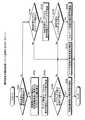
つぎに図2を参照し、RAIDグループの構成変更処理におけるバッファの利用について説明する。図2に示した例は、RAID5(3+1)からRAID5(4+1)への変更である。 Next, the use of a buffer in the RAID group configuration change process will be described with reference to FIG. The example shown in FIG. 2 is a change from RAID 5 (3 + 1) to RAID 5 (4 + 1).
RAID5(3+1)は、4本のディスクのうち、3本分の容量をデータ保存用に使用して、1本分の容量を冗長化データの保存に使用する。同様にRAID5(4+1)は、5本のディスクのうち、4本分の容量をユーザデータ保存用に使用して、1本分の容量を冗長化データの保存に使用する。そして、RAID5では、ユーザデータについても、冗長化データについても各ディスクに分散して保存する。 RAID 5 (3 + 1) uses the capacity of three of the four disks for storing data and the capacity of one for storing redundant data. Similarly, RAID 5 (4 + 1) uses the capacity of four of the five disks for storing user data and the capacity of one for storing redundant data. In RAID5, both user data and redundant data are distributed and stored in each disk.
より詳細には、ディスクに対するアクセス単位を各ディスクから1単位ずつ取得したものが1ストライプであり、RAIDグループに対する読み書きの単位となる。そして、各ストライプには1つずつ冗長化データが存在し、いずれのディスクが冗長化データを保持しているかはストライプごとに異なる。なお、RAID5での冗長化データには排他的論理和によるパリティを用いることが一般的であるので、以降、RAID5での冗長化データをパリティとして説明する。また、ディスクに対するデータの読み書きの説明については、上述した読み書き単位をデータ1つ分として説明する。 More specifically, one stripe obtained by obtaining an access unit for each disk from each disk is one stripe, which is a read / write unit for the RAID group. Each stripe has one redundant data, and which disk holds the redundant data differs for each stripe. In addition, since it is common to use the parity by exclusive OR for the redundant data in RAID5, the redundant data in RAID5 will be described as parity hereinafter. In addition, regarding the reading / writing of data to / from the disk, the above-described reading / writing unit is described as one piece of data.
RAID5(3+1)からRAID5(4+1)に構成を変更する場合、旧構成であるRAID5(3+1)からユーザデータを読み出して一旦バッファに格納する。この旧構成からの読み出しは旧構成のストライプ単位で行なう。そして読み出しは冗長化データであるパリティを除いたユーザデータに対して行なう。したがって、旧構成がRAID5(3+1)であればディスクから読み出されるデータ数は3の倍数(読み書き単位3つ分の倍数のデータ)となる。 When the configuration is changed from RAID 5 (3 + 1) to RAID 5 (4 + 1), user data is read from the old configuration RAID 5 (3 + 1) and temporarily stored in the buffer. Reading from the old configuration is performed in stripe units of the old configuration. Reading is performed on user data excluding parity, which is redundant data. Therefore, if the old configuration is RAID 5 (3 + 1), the number of data read from the disk is a multiple of 3 (data of a multiple of three read / write units).
バッファに格納したユーザデータは、その後、ディスクを1本追加した新構成RAID5(4+1)に書き戻され、新構成でのパリティが計算される。この新構成への書き戻しは新構成のストライプ単位で行なう。そのため新構成がRAID5(4+1)であればディスクに書き込むデータは、アクセス単位4つ分のユーザデータにアクセス単位1つ分のパリティを加えたアクセス単位5つ分の倍数のデータとなる。 The user data stored in the buffer is then written back to the new configuration RAID 5 (4 + 1) with one additional disk, and the parity in the new configuration is calculated. This write back to the new configuration is performed in units of stripes of the new configuration. Therefore, if the new configuration is RAID 5 (4 + 1), the data to be written to the disk is a multiple of five access units obtained by adding the parity for one access unit to the user data for four access units.
このように、旧構成からの読み出しは旧構成のストライプ単位で行ない、新構成への書き込みは新構成のストライプ単位で行なう。そのため、旧構成から読み出してバッファに格納するデータ数、またバッファから新構成に書き戻すデータ数を、旧構成の1ストライプ内のデータ数と新構成の1ストライプ内のデータ数との公倍数とすることが好ましい。 Thus, reading from the old configuration is performed in units of stripes of the old configuration, and writing to the new configuration is performed in units of stripes of the new configuration. Therefore, the number of data read from the old configuration and stored in the buffer, and the number of data written back to the new configuration from the buffer is the common multiple of the number of data in one stripe of the old configuration and the number of data in one stripe of the new configuration. It is preferable.
例えば、RAID5(3+1)からRAID5(4+1)に構成変更する場合、旧構成の1ストライプ内のデータ数である3と新構成の1ストライプ内のデータ数である4との公倍数である12を用い、旧構成から4ストライプ分のデータを読み出して新構成に3ストライプ分のデータを書き込むようにすれば、読み書きのデータ数を揃えることができる。 For example, when the configuration is changed from RAID 5 (3 + 1) to RAID 5 (4 + 1), 12 which is a common multiple of 3 which is the number of data in one stripe of the old configuration and 4 which is the number of data in one stripe of the new configuration is used. If the data of 4 stripes is read from the old configuration and the data of 3 stripes is written to the new configuration, the number of read / write data can be made uniform.
なお、RAIDグループに対する1回のアクセスでのデータ数にも上限があるので、旧構成の1ストライプ内のデータ数と新構成の1ストライプ内のデータ数との公倍数のうち、1アクセスでの上限以下の最大の値を用いることが好適である。 Since there is an upper limit for the number of data in one access to the RAID group, the upper limit for one access is a common multiple of the number of data in one stripe of the old configuration and the number of data in one stripe of the new configuration. It is preferred to use the following maximum values:
つぎにメモリ12に格納する各種データの具体例について説明する。図3は、RAID管理テーブル12aの具体例について説明する説明図である。図3に示した管理テーブル12aは、「RAIDグループ番号」、「RAIDレベル」、「RAIDグループステータス」、「メンバーディスク数」、「メンバーディスク」、「構成変更モード」、「構成変更優先度」の各項目を有する。 Next, specific examples of various data stored in the
「RAIDグループ番号」は、ストレージシステム内でRAIDグループを識別する番号であり、「RAIDレベル」はそのRIADグループのRAIDレベルを、「RAIDグループステータス」は、そのRAIDグループの状態を示す。RAIDグループステータスの値としては、正常な状態を示すAvailable、ディスク故障によって冗長性が失われた状態を示すExposed、RAIDグループが使用できない状態を示すBroken、データ復元中の状態を示すRebuild、などがある。 “RAID group number” is a number for identifying a RAID group in the storage system, “RAID level” indicates the RAID level of the RIAD group, and “RAID group status” indicates the state of the RAID group. The RAID group status values include “Available” indicating a normal state, “Exposed” indicating a state in which redundancy has been lost due to a disk failure, “Broken” indicating a state in which the RAID group cannot be used, “Rebuild” indicating a state during data restoration, etc. is there.
「メンバーディスク数」は、RAIDグループに所属するディスクの数を示す値であり、「メンバーディスク」は、RAIDグループに所属する各ディスクの番号である。 “Number of member disks” is a value indicating the number of disks belonging to the RAID group, and “member disk” is the number of each disk belonging to the RAID group.
「構成変更モード」は、RAID構成変更処理部16が構成変更を行なう際のスペアディスクの扱いを設定する項目であり、可逆変換保証、サルベージ保証、スペア不使用のいずれかの値を取る。この値は、RAIDグループの作成時に選択することができ、また構成変更の実行中以外であれば随時変更可能である。 The “configuration change mode” is an item for setting the handling of the spare disk when the RAID configuration
可逆変換保証は、構成変更にかかるデータの全てをスペアディスクに保持する、すなわち実施中の構成変更が完了するまでは新構成に書き戻されたデータについても保持することで、旧構成への差し戻しを可能とする。この可逆変換保証の構成変更では、RAIDグループ内のデータを全て保持するだけの容量のスペアディスク本数が必要となる。 Reversible conversion guarantees that all data related to configuration changes are retained on the spare disk, that is, data that has been written back to the new configuration is retained until the configuration change in progress is completed. Is possible. This reversible conversion guarantee configuration change requires the number of spare disks having a capacity sufficient to hold all data in the RAID group.
サルベージ保証は、仕掛かり中領域のデータを1本のスペアディスクに保持することで、メモリ故障やバックアップ失敗による揮発性バッファ上のデータロストに対応するものである。このサルベージ保証の構成変更では、旧構成から読み出されたデータは、新構成に書き戻されるまではスペアディスク上に保持する。 In the salvage guarantee, the data in the in-process area is held in one spare disk, which corresponds to data loss on the volatile buffer due to memory failure or backup failure. In this salvage guarantee configuration change, data read from the old configuration is held on the spare disk until it is written back to the new configuration.
スペア不使用は、スペアディスクを使用せず、構成変更にかかるデータを冗長化しない、従来の構成変更と同じ処理を実行することを示す。 Spare nonuse indicates that a spare disk is not used and data related to the configuration change is not made redundant, and the same processing as the conventional configuration change is executed.
すなわち、構成変更モードは、構成変更における冗長化の程度を示すものであり、構成変更の信頼度を3段階のレベルとして定義したものである。 That is, the configuration change mode indicates the degree of redundancy in the configuration change, and defines the reliability of the configuration change as three levels.
「構成変更優先度」は、構成変更の冗長化にスペアディスクを使用している状態で、ディスク故障が発生した場合に、構成変更の信頼度レベルの維持を優先するか、ディスク故障対応、すなわち、RAIDグループの冗長性復旧を優先するかを示す項目である。 “Configuration change priority” is a status in which a spare disk is used for configuration change redundancy, and if a disk failure occurs, priority is given to maintaining the reliability level of the configuration change, This item indicates whether to give priority to the redundancy recovery of the RAID group.
具体的には、構成変更優先度の項目は、構成変更優先、自グループのディスク故障対応優先、ディスク故障対応優先、のいずれかの値を取る。この値は、RAIDグループの作成時に選択することができ、また構成変更の実行中以外であれば随時変更可能である。 Specifically, the configuration change priority item takes one of the values of configuration change priority, disk failure handling priority of the own group, and disk failure handling priority. This value can be selected when a RAID group is created, and can be changed at any time except when a configuration change is being executed.
構成変更優先度の項目に構成変更優先を設定したRAIDグループは、構成変更が完了するまではスペアディスクを保持し、ディスク故障が発生した場合であってもスペアディスクをリビルド動作に使用しない。 A RAID group for which configuration change priority is set in the configuration change priority item holds a spare disk until the configuration change is completed, and does not use the spare disk for a rebuild operation even if a disk failure occurs.
構成変更優先度の項目に自グループのディスク故障対応優先を設定したRAIDグループは、構成変更中に自グループ内でディスク故障が発生した場合には、構成変更を冗長化するために使用していたスペアディスクを解放し、自グループ内のディスク故障対応を優先してRAIDグループの冗長性を復旧させる。しかし、他のグループでディスク故障が発生した場合ではスペアディスクを解放しない。 The RAID group in which the priority of disk failure in the own group is set in the configuration change priority item was used to make the configuration change redundant when a disk failure occurred in the own group during the configuration change. The spare disk is released, and the redundancy of the RAID group is restored by giving priority to the disk failure within the own group. However, if a disk failure occurs in another group, the spare disk is not released.
構成変更優先度の項目にディスク故障対応優先を設定したRAIDグループは、構成変更中にディスク故障が発生した場合には、故障が発生したディスクが他のグループであっても構成変更の冗長化に使用していたスペアディスクを解放し、RAIDグループの冗長性を復旧させる。 If a disk failure occurs during a configuration change in a RAID group in which the configuration change priority item is set to a disk failure priority, the configuration change can be made redundant even if the failed disk is in another group. The used spare disk is released, and the redundancy of the RAID group is restored.
図4は、ディスク管理テーブル12bの具体例について説明する説明図である。図4に示したディスク管理テーブル12bは、「ディスク番号」、「ディスクステータス」、「付加情報ビット」、「所属RAIDグループ」の各項目を有する。なおここでは、付加情報をビットで管理しているが、付加情報はフラグなど任意の方法で管理することができる。 FIG. 4 is an explanatory diagram illustrating a specific example of the disk management table 12b. The disk management table 12b shown in FIG. 4 has items of “disk number”, “disk status”, “additional information bit”, and “affiliated RAID group”. Although the additional information is managed by bits here, the additional information can be managed by an arbitrary method such as a flag.
「ディスク番号」は、ストレージシステム内でディスクを識別する番号であり、「ディスクステータス」は、ディスクの状態を示す。ディスクステータスの値としては、正常な状態を示すAvailable、故障状態を示すBroken、RAIDグループに所属していない状態を示すPresent、データ復元中の状態を示すRebuild、スペアディスクに設定されていることを示すSpareなどがある。 “Disk number” is a number for identifying a disk in the storage system, and “disk status” indicates the state of the disk. The disk status values are set to “Available” indicating a normal state, “Broken” indicating a failure state, “Present” indicating a state not belonging to a RAID group, “Rebuild” indicating a state during data restoration, and “spare disk”. There are Spare and the like shown.
「付加情報ビット」は、ディスクステータスに付加することでディスクの状態をさらに詳細に示すものであり、EnableIOビット、SMARTビット、LDEビット、QFビット、LDE_HSビットの5ビットである。 The “additional information bit” indicates the state of the disc in more detail by being added to the disc status, and is 5 bits of an EnableIO bit, a SMART bit, an LDE bit, a QF bit, and an LDE_HS bit.
EnableIOビットは、アクセス処理部13からのアクセスを受付か可能であるか否かを示すビットである。SMARTビットは、ディスク単体での異常が発生しているか否かを示すビットである。LDEビットは、構成変更を実施中であるか否かを示すビットであり、例えば構成変更を実施中である場合に1、構成変更を実施中で無い場合に0の値をとる。QFビットは、フォーマットを実施中であるか否かを示すビットである。そして、LDE_HSビットは、構成変更の冗長化に使用中であるか否かを示すビットである。 The EnableIO bit is a bit indicating whether or not the access from the
したがって、ディスクステータスの値がSpareであるディスクについて、LDE_HSビットを確認すれば、そのスペアディスクが構成変更の冗長化に使われておらず、そのままRAIDグループの冗長化復旧に使用可能な状態であるのか、構成変更の冗長化に使用中でRAIDグループの冗長化復旧に使用するためには構成変更との競合解消が必要であるのかを判別することができる。 Therefore, if the LDE_HS bit is confirmed for the disk whose value of the disk status is Spare, the spare disk is not used for the redundancy of the configuration change, and can be used for the redundancy recovery of the RAID group as it is. However, it is possible to determine whether it is necessary to resolve the conflict with the configuration change in order to use it for redundancy recovery of the RAID group while being used for redundancy of the configuration change.
「所属RAIDグループ」は、そのディスクが所属するRAIDグループ番号である。スペアディスクである場合など、RAIDグループに所属していない場合には、この項目の値はブランクとする。 “Affiliated RAID group” is a RAID group number to which the disk belongs. If the disk does not belong to a RAID group, such as a spare disk, the value of this item is blank.
図5は、バッファ管理テーブル12cの具体例について説明する説明図である。図5に示したバッファ管理テーブル12cは、バッファアドレスと実アドレス、バッファグループを対応付け、さらにバッファ全体に対して使用中先頭アドレスと使用中最終アドレスの値を有する。 FIG. 5 is an explanatory diagram illustrating a specific example of the buffer management table 12c. The buffer management table 12c shown in FIG. 5 associates a buffer address with a real address and a buffer group, and has values of a used start address and a used last address for the entire buffer.
バッファアドレスは、構成変更時に旧構成から読み出したデータを新構成に書き戻すまでの間保持するバッファの仮想的なアドレスであり、実アドレスが仮想アドレスのメモリ上での実際の位置を規定している。そして仮想バッファは、リングバッファであり、使用中先頭アドレスが使用中の先頭位置を、使用中最終アドレスが使用中の最終位置を示している。 The buffer address is a virtual address of the buffer that is held until the data read from the old configuration is written back to the new configuration when the configuration is changed, and the real address defines the actual location of the virtual address in the memory. Yes. The virtual buffer is a ring buffer, where the in-use top address indicates the start position in use, and the in-use final address indicates the end position in use.
また、構成変更時にはバッファを第1バッファと第2バッファに分けて使用するので、バッファグループの値によって仮想のバッファアドレスと実アドレスが第1バッファとして使用中であるのか、第2バッファとして使用中であるのかを示している。なお、使用中最終アドレスから使用中先頭アドレスまでの間は使用していないアドレス範囲であるので、バッファグループの値はブランクである。 Since the buffer is divided into the first buffer and the second buffer when the configuration is changed, whether the virtual buffer address and the real address are being used as the first buffer or being used as the second buffer depending on the value of the buffer group. Is shown. Since the range from the last used address to the first used address is an unused address range, the value of the buffer group is blank.
つぎに、構成変更の開始について説明する。図6は、構成変更の開始処理について説明するフローチャートである。RAID構成変更処理部16は、RAIDグループの構成変更を行なう場合にRAID管理テーブル12aを参照し、対象となるRAIDグループの構成変更モードが可逆変換保証であるか否かを判定する(S101)。 Next, the start of the configuration change will be described. FIG. 6 is a flowchart illustrating the configuration change start process. The RAID configuration
構成変更モードが可逆変換保証である場合(S101,Yes)、スペアディスク確保部16aは、構成変更前のRAID構成から可逆変換保証に使用するスペアディスクの本数を算出する(S102)。なお、構成変更モードが設定されたタイミングで、予めテーブル上に必要なスペアディスク数を記憶させておいてもよい。さらに、スペアディスク確保部16aは、ディスク管理テーブル12bを参照し、使用可能なスペアディスク数を求める(S103)。具体的には、スペアディスク確保部16aは、ディスクステータスがspareで、かつ付加情報ビットが構成変更を実施中でないことを示しているディスクの数を集計する。そして、使用可能なスペアディスクの数が必要な数以上であれば(S104,Yes)、RAID構成変更部16は可逆変換保証の構成変更を開始する(S105)。 When the configuration change mode is reversible conversion guarantee (S101, Yes), the spare disk securing unit 16a calculates the number of spare disks used for reversible conversion guarantee from the RAID configuration before the configuration change (S102). Note that the number of necessary spare disks may be stored in advance on the table at the timing when the configuration change mode is set. Further, the spare disk securing unit 16a refers to the disk management table 12b and obtains the number of usable spare disks (S103). Specifically, the spare disk securing unit 16a counts the number of disks indicating that the disk status is “spare” and the additional information bits are not undergoing a configuration change. If the number of usable spare disks is equal to or greater than the necessary number (S104, Yes), the RAID
一方、構成変更モードが可逆変換保証で無い場合(S101,No)、RAID構成変更処理部16は、RAID管理テーブル12aを参照し、対象となるRAIDグループの構成変更モードがサルベージ保証であるか否かを判定する(S106)。 On the other hand, when the configuration change mode is not reversible conversion guarantee (S101, No), the RAID configuration
構成変更モードがサルベージ保証である場合(S106,Yes)、スペアディスク確保部16aは、ディスク管理テーブル16bを参照し、使用可能なスペアディスクを検索する(S107)。使用可能なスペアディスクがあれば(S108,Yes)、RAID構成変更部16はサルベージ保証の構成変更を開始する(S109)。 When the configuration change mode is salvage guarantee (S106, Yes), the spare disk securing unit 16a refers to the disk management table 16b and searches for an available spare disk (S107). If there is an available spare disk (S108, Yes), the RAID
そして、構成変更モードがスペア不使用である場合(S106,No)、構成変更モードが可逆変換保証であって使用可能なスペアディスクの数が必要な数に満たない場合(S104,No)、および構成変更モードがサルベージ保証であって使用可能なスペアディスクが無い場合(S108,No)、RAID構成変更部16は、スペア不使用の構成変更を開始する(S110)。 When the configuration change mode is spare not used (S106, No), when the configuration change mode is reversible conversion guarantee and the number of usable spare disks is less than the required number (S104, No), and If the configuration change mode is salvage guarantee and there is no usable spare disk (S108, No), the RAID
つぎに、構成変更の冗長化とRAIDグループの冗長性復旧との競合解消について説明する。図7は、構成変更の実行中にディスク故障が発生した場合のストレージコントローラの処理動作を説明するフローチャートである。 Next, the conflict resolution between the redundancy of the configuration change and the redundancy recovery of the RAID group will be described. FIG. 7 is a flowchart for explaining the processing operation of the storage controller when a disk failure occurs during execution of the configuration change.
構成変更の実行中にディスク故障が発生すると、ストレージコントローラ10内部の冗長性復旧処理部14は、ディスク管理テーブル12bを参照し、冗長性復旧に使用可能なスペアディスク、すなわち、スペアディスクに設定されており、かつ構成変更の冗長化に使用されていないスペアディスクがストレージシステム内に存在するか否かを判定する(S201)。使用可能なスペアディスクが存在する場合(S201,Yes)、冗長性復旧処理部14は、使用可能なスペアディスクを使用して冗長性復旧処理を開始する(S207)。 If a disk failure occurs during the configuration change, the redundancy
使用可能なスペアディスクが無い場合(S201,No)、冗長性復旧処理部14は、RAID管理テーブル12aを参照し、故障したディスクが所属するRAIDグループがスペアディスクを使用した構成変更を実行中であるか否かを判定する(S202)。 When there is no usable spare disk (S201, No), the redundancy
故障したディスクが所属するRAIDグループがスペアディスクを使用した構成変更を実行中である場合(S202,Yes)、冗長性復旧処理部14はRAID管理テーブル12aの構成変更優先度を確認し、そのグループがスペアディスクを解放可能であるか否かを判定する(S203)。ここでは構成変更中のRAIDグループ内でディスク故障が発生しているので、構成変更優先度が自グループのディスク故障対応優先、もしくはディスク故障対応優先である場合にスペアディスク解放可能となる。 When the RAID group to which the failed disk belongs is executing a configuration change using a spare disk (S202, Yes), the redundancy
同一グループでスペアディスクを解放可能であれば(S203,Yes)、RAID構成変更処理部16は、構成変更前の旧構成がRAID1であるか否かを判定する(S204)。 If the spare disk can be released in the same group (S203, Yes), the RAID configuration
旧構成がRAID1である場合(S204,Yes)、スペアディスク確保部16aが確保しているスペアディスクは1本であるので、スペアディスク確保部16aは、確保していたスペアディスクを解放し、変更処理冗長化部16bは、スペア不使用の構成変更として処理を継続する(S208)。 When the old configuration is RAID 1 (S204, Yes), the spare disk securing unit 16a secures one spare disk, so the spare disk securing unit 16a releases and changes the reserved spare disk. The process redundancy unit 16b continues the process as a spare-unused configuration change (S208).
一方、旧構成がRAID1で無ければ(S204,No)、変更処理冗長化部16bは、仕掛かり中の拡張範囲、すなわち、旧構成から読み出してバッファ上に存在するデータを使用中のスペアディスクのうちの1本に格納する(S205)。その後、スペアディスク確保部16aは、バッファデータを格納したスペアディスク以外のスペアディスクを解放し、変更処理冗長化部16bは、サルベージ保証の構成変更として処理を継続する(S206)。そして、冗長性復旧処理部14は、スペアディスク確保部16aが解放したスペアディスクを使用して冗長性復旧処理を開始する(S207)。 On the other hand, if the old configuration is not RAID 1 (S204, No), the change processing redundancy unit 16b reads the extended range being processed, that is, the spare disk that is using the data read from the old configuration and existing on the buffer. It stores in one of them (S205). Thereafter, the spare disk securing unit 16a releases spare disks other than the spare disk storing the buffer data, and the change processing redundancy unit 16b continues the processing as the salvage guarantee configuration change (S206). Then, the redundancy
そして、故障したディスクが属するRAIDグループがスペアディスクを使用した構成変更を実施中ではない場合(S202,No)、故障したディスクが属するRAIDグループの構成変更優先度からスペアディスクの解放ができない場合(S203,No)、冗長性復旧処理部14は、RAID管理テーブル12aを参照し、ストレージシステム内にスペアディスクを使用した構成変更を実行中のRAIDグループがあるか否かを判定する(S209)。 If the RAID group to which the failed disk belongs is not currently undergoing a configuration change using a spare disk (No in S202), the spare disk cannot be released from the configuration change priority of the RAID group to which the failed disk belongs ( (S203, No), the redundancy
故障したディスクが所属するRAIDグループ以外にスペアディスクを使用した構成変更を実行中のRAIDグループが存在する場合(S209,Yes)、冗長性復旧処理部14はRAID管理テーブル12aの構成変更優先度を確認し、スペアディスクを使用した構成変更中のRAIDグループが、他のグループに対してスペアディスクを解放可能であるか否かを判定する(S210)。ここでは構成変更中のRAIDグループ外でディスク故障が発生していることになるので、構成変更優先度がディスク故障対応優先である場合にスペアディスク解放可能となる。 When there is a RAID group that is executing a configuration change using a spare disk in addition to the RAID group to which the failed disk belongs (S209, Yes), the redundancy
他のRAIDグループに解放可能なスペアディスクがある場合(S210,Yes)、RAID構成変更処理部16は、スペアディスクを解放可能なRAIDグループに、構成変更前の旧構成がRAID1以外のものがあるか否かを判定する(S211)。 When there is a releasable spare disk in another RAID group (S210, Yes), the RAID configuration
RAID1以外の構成からスペアディスクを解放できる場合(S211,Yes)、変更処理冗長化部16bは、そのRAIDグループの仕掛かり中の拡張範囲、すなわち、旧構成から読み出してバッファ上に存在するデータを、使用中のスペアディスクのうちの1本に格納する(S205)。その後、スペアディスク確保部16aは、バッファデータを格納したスペアディスク以外のスペアディスクを解放し、変更処理冗長化部16bは、サルベージ保証の構成変更として処理を継続する(S206)。そして、冗長性復旧処理部14は、スペアディスク確保部16aが解放したスペアディスクを使用して冗長性復旧処理を開始する(S207)。 If the spare disk can be released from a configuration other than RAID 1 (S211, Yes), the change processing redundancy unit 16b reads the data that exists in the buffer after reading from the extended range in progress of the RAID group, that is, from the old configuration. Then, it is stored in one of the used spare disks (S205). Thereafter, the spare disk securing unit 16a releases spare disks other than the spare disk storing the buffer data, and the change processing redundancy unit 16b continues the processing as the salvage guarantee configuration change (S206). Then, the redundancy
一方、スペアディスクを解放できるRAIDグループの旧構成がRAID1である場合(S211,No)、確保しているスペアディスクは1本であるので、スペアディスク確保部16aは、確保していたスペアディスクを解放し、変更処理冗長化部16bは、スペア不使用の構成変更として処理を継続する(S208)。そして、冗長性復旧処理部14は、スペアディスク確保部16aが解放したスペアディスクを使用して冗長性復旧処理を開始する(S207)。 On the other hand, if the old configuration of the RAID group that can release the spare disk is RAID 1 (No in S211), the spare disk securing unit 16a determines the reserved spare disk because there is only one spare disk secured. The change processing redundancy unit 16b continues the processing as a spare-unused configuration change (S208). Then, the redundancy
つぎに、ストレージコントローラ10による構成変更の具体例について説明する。ここでは、RAID(3+1)からRAID(4+1)にサルベージ保証で構成変更する場合を例示する。旧構成のRAID(4+1)は、ディスクD11,21,31,41からなる。この構成に新たにディスクDxを加えてRAID(4+1)とする。また、構成変更にかかるデータの一時的な保持にはバッファBfを用いる。さらに、スペアディスク確保部16は、構成変更の開始時点にスペアディスクとしてディスクDsを確保している。 Next, a specific example of the configuration change by the
まず、図8に示したように、RAID構成変更処理部16は、旧構成から2ストライプ分のデータを読み出してバッファBfに格納する。ここで、ディスクD41の一つ目のデータとディスクD31の2つ目のデータはパリティであるので読み出さず、旧構成から読み出すデータ数は6となる。RAID構成変更処理部16は、読み出したデータをバッファBfに格納し、格納した領域を第1バッファ12dとする。 First, as shown in FIG. 8, the RAID configuration
バッファBfへの格納は、より詳細には、必要なバッファの数だけバッファ管理テーブル12cの使用中最終アドレスを加算する。この加算において、最終アドレスに達した場合には続きはバッファアドレス「0」からカウントする。この加算によって使用中最終アドレスが使用中先頭アドレスを追い越さなければバッファの獲得が成功する。RAID構成変更処理部16は、獲得したバッファのバッファグループの値を第1バッファとし、獲得した第1バッファに旧構成から読み出したデータを格納する。 More specifically, the storage in the buffer Bf adds the in-use final address of the buffer management table 12c by the number of necessary buffers. In this addition, when the final address is reached, the continuation is counted from the buffer address “0”. As a result of this addition, the buffer is successfully acquired if the in-use final address does not pass the in-use head address. The RAID configuration
つぎに、変更処理冗長化部16bが、第1バッファ12dから4つ分のデータを読み出してディスクDsに書き込むことで第1バッファ12dのデータを冗長化し、RAID構成変更処理部16は旧構成から2ストライプ分のデータを読み出してバッファBfに第2バッファ12eとして格納する。 Next, the change processing redundancy unit 16b reads four data from the
このように、第1バッファからスペアディスクへの書き込みと旧構成から第2バッファへの読み出しとを並行して行なうことで、バッファからスペアディスクへの冗長化を行なわない構成変更処理に対して処理遅延が発生することを防ぐことができる。 In this way, processing for the configuration change process that does not provide redundancy from the buffer to the spare disk by performing writing from the first buffer to the spare disk and reading from the old configuration to the second buffer in parallel is performed. A delay can be prevented from occurring.
また、バッファからディスクDsへの書き込みを行なうデータ数を4としたのは、新構成への書き戻しが1ストライプ分、すなわちデータ数が4であることに対応したものである。 The number of data to be written from the buffer to the disk Ds is set to 4 because the write back to the new configuration is for one stripe, that is, the number of data is 4.
つづいて、図9に示したように、RAID構成変更処理部16はバッファBfの第1バッファ12dから新構成の1ストライプ分に相当する4つ分のデータを読み出して新構成のディスクD11,21,31,41に書き戻すとともに、パリティを計算してディスクDxに書き込む。 Subsequently, as shown in FIG. 9, the RAID configuration
旧構成から読み出すデータ数と新構成に書き戻すデータ数とを一致させることができる場合、すなわち、旧構成の1ストライプあたりのデータ数と新構成の1ストライプあたりのデータ数との公倍数にRAIDグループアクセスの上限以下の値がある場合には、第1バッファの全てを一度に書き戻すことができる。 When the number of data read from the old configuration can be matched with the number of data written back to the new configuration, that is, the RAID group has a common multiple of the number of data per stripe of the old configuration and the number of data per stripe of the new configuration. If there is a value below the upper limit of access, all of the first buffer can be written back at once.
しかし、図9で示した例では、旧構成からの読み出しデータ数が6、新構成への書き戻しデータ数が4で一致していない。そのため、新構成への書き戻しを行なった後、第1バッファ12dにデータが2つ分残ることとなる。変更処理冗長化部16bは、第1バッファ12dからの書き戻し後に残されたデータを第2バッファ12eの先頭部分とするバッファ調整を行なったうえで、第1バッファ12dを解放する。バッファの解放は、バッファ管理テーブル12cにおいて、使用中先頭アドレスを加算することで行なう。この加算において、最終アドレスに達した場合には続きはバッファアドレス「0」からカウントする。使用中先頭アドレスは、使用中開始アドレスに一致することはあるが、追い越すことは無い。 However, in the example shown in FIG. 9, the number of read data from the old configuration is 6, and the number of write-back data to the new configuration is 4, which does not match. Therefore, after writing back to the new configuration, two pieces of data remain in the
つづいて、図10に示したように、変更処理冗長化部16bが、第2バッファ12eから4つ分のデータを読み出してディスクDsに書き込むことで第2バッファ12eのデータを冗長化し、RAID構成変更処理部16は旧構成から2ストライプ分のデータを読み出してバッファBfに第1バッファ12dとして格納する。なお、バッファBfとスペアディスクDsはリング状に使用しており、記憶領域の終端まで書き込んだ後は次のデータを先頭から書き込んでいく。 Subsequently, as shown in FIG. 10, the change processing redundancy unit 16b reads the data for four pieces from the
その後、RAID構成変更処理部16はバッファBfの第2バッファ12eから新構成の1ストライプ分に相当する4つ分のデータを読み出して新構成のディスクD11,21,31およびDxに書き戻すとともに、パリティを計算してディスクD41に書き込む。そして、変更処理冗長化部16bは、第2バッファ12eからの書き戻し後に残されたデータを第1バッファ12dの先頭部分とするバッファ調整を行なったうえで、第2バッファ12eを解放する。 Thereafter, the RAID configuration
以降、RAID構成変更処理部16は、第2バッファへの読み出しと第1バッファの冗長化、第1バッファの書き戻しとバッファ調整、第1バッファへの読み出しと第2バッファの冗長化、第2バッファの書き戻しとバッファ調整、を繰り返すことで構成変更を進めていく。 Thereafter, the RAID configuration
上述してきたように、本実施例では、RAIDグループの構成変更を行なう場合に、旧構成から読み出したデータをバッファ上に置いた上で、データをスペアディスクに書き込んで冗長化する。このとき構成変更実施中のデータはRAIDグループを構成するディスク、スペアディスクおよびバッファ上に存在している。その後、データを新構成としてRAIDグループを構成するディスクに書き戻すので、新構成への書き込み中にバッファ上のデータに異常が生じた場合も、変更処理復旧処理部16cがスペアディスクからデータを読み出して変更処理の継続が可能となる。また、十分な数のスペアディスクを確保して構成変更にかかるデータを全て保持する可逆変換保証では、変更処理復旧処理部16cがスペアディスクからデータを読み出して旧構成として書き戻すことにより、任意のタイミングで構成変更を中止して旧構成に戻すことができる。 As described above, in this embodiment, when changing the configuration of a RAID group, data read from the old configuration is placed on a buffer, and then the data is written to a spare disk for redundancy. At this time, the data whose configuration is being changed exists on the disks, spare disks, and buffers constituting the RAID group. Thereafter, the data is written back to the disks constituting the RAID group as a new configuration, so that even if an error occurs in the data on the buffer during writing to the new configuration, the change processing recovery processing unit 16c reads the data from the spare disk. The change process can be continued. Further, in the reversible conversion guarantee in which a sufficient number of spare disks are secured and all the data related to the configuration change is retained, the change processing recovery processing unit 16c reads the data from the spare disk and writes it back as the old configuration, so that an arbitrary configuration can be obtained. The configuration change can be canceled and the old configuration can be restored at the timing.
また、構成変更処理に使用するバッファを2つの群に分け、旧構成から読み出したデータをバッファの一方に書き込んでいる間に他方のバッファからスペアディスクへの書き込みを行なうことで、スペアディスクへの書き込み処理が追加されることによる処理遅延の影響を抑制している。 In addition, the buffers used for the configuration change processing are divided into two groups, and while data read from the old configuration is written to one of the buffers, writing to the spare disk from the other buffer is performed, so that The effect of processing delay due to the addition of writing processing is suppressed.
さらに、RAIDグループにおける冗長性確保用に用意したスペアディスクを構成変更処理の冗長化に用いるとともに、RAIDグループにおける冗長性確保と構成変更処理の冗長化との間の優先関係を規定することによって、システム構築に要するコストを上昇させることなく構成変更中のデータ消失を防止し、また、構成変更を中断して元の構成に復旧することができる。 Furthermore, by using the spare disk prepared for ensuring redundancy in the RAID group for redundancy of the configuration change process, and defining the priority relationship between redundancy ensuring in the RAID group and redundancy of the configuration change process, Data loss during the configuration change can be prevented without increasing the cost required for system construction, and the configuration change can be interrupted to restore the original configuration.
なお、本実施例ではハードディスクをストレージデバイスとして用いるRAIDシステムを例に説明を行なったが、開示の技術はこれに限定されるものではなく、任意の記録媒体を用いて実施することができるものである。 In this embodiment, a RAID system using a hard disk as a storage device has been described as an example. However, the disclosed technology is not limited to this, and can be implemented using any recording medium. is there.
以上の各実施例を含む実施形態に関し、さらに以下の付記を開示する。 The following supplementary notes are further disclosed with respect to the embodiments including the above examples.
(付記1)ユーザデータを格納するデータストレージと、前記データストレージにおける障害発生時に使用するスペアストレージとを管理するストレージ管理装置であって、
前記データストレージをグループ化し、同一グループに属するデータストレージ間で前記ユーザデータの分散および/または冗長化を行なうグループ管理部と、
前記データストレージに障害が発生した場合に、前記スペアストレージを代替のデータストレージとして割り当てるデータストレージ復旧処理部と、
前記データストレージのグループの構成変更を行なう構成変更処理部と
を備え、
前記構成変更処理部は、
前記スペアストレージを確保するスペアストレージ確保部と、
前記グループの構成変更処理にかかるデータを前記スペアストレージ確保部が確保したスペアストレージに書き込む変更処理冗長化部と、
前記グループの構成変更が中断した場合に前記スペアストレージに書き込んだデータを用いて前記グループの構成変更の継続もしくは前記グループの変更開始前の状態への復旧を行なう変更処理復旧処理部と
を備えたことを特徴とするストレージ管理装置。(Supplementary note 1) A storage management device for managing data storage for storing user data and spare storage used when a failure occurs in the data storage,
A group management unit that groups the data storages and distributes and / or makes the user data distributed among data storages belonging to the same group;
A data storage recovery processing unit that allocates the spare storage as an alternative data storage when a failure occurs in the data storage;
A configuration change processing unit for changing the configuration of the data storage group;
The configuration change processing unit
A spare storage securing unit for securing the spare storage;
A change processing redundancy unit that writes data related to the group configuration change process to the spare storage secured by the spare storage securing unit;
A change processing recovery processing unit for continuing the configuration change of the group using the data written in the spare storage when the group configuration change is interrupted, or restoring the state before the start of the group change. A storage management device.
(付記2)前記構成変更部は、前記グループの構成変更を行なう場合に、構成変更前のデータストレージから読み出した前記ユーザデータを第1バッファと第2バッファに交互に書き込み、前記変更処理冗長化部は、第2バッファに対する書き込み処理中に前記第1バッファに書き込まれたユーザデータを読み出して前記スペアストレージ確保部が確保したスペアストレージに書き込み、前記第1バッファに対する書き込み処理中に前記第2バッファに書き込まれたユーザデータを読み出して前記スペアストレージ確保部が確保したスペアストレージに書き込むことを特徴とする付記1に記載のストレージ管理装置。(Additional remark 2) When the said structure change part performs the structure change of the said group, the said user data read from the data storage before a structure change are written in the 1st buffer and the 2nd buffer alternately, The said change process redundancy The unit reads the user data written to the first buffer during the writing process to the second buffer, writes the user data to the spare storage secured by the spare storage securing unit, and the second buffer during the writing process to the first buffer. The storage management device according to
(付記3)前記スペアストレージ確保部は、前記グループの構成変更において当該グループに属するデータストレージから読み出す全ユーザデータを格納可能な1以上のスペアストレージを確保することを特徴とする付記1または2に記載のストレージ管理装置。(Supplementary note 3) According to
(付記4)前記スペアストレージ確保部は、前記グループの構成変更において当該グループに属するデータストレージから読み出したユーザデータを構成変更後のデータストレージに書き戻すまで格納可能なスペアストレージを確保することを特徴とする付記1または2に記載のストレージ管理装置。(Supplementary Note 4) The spare storage securing unit reserves a spare storage that can be stored until the user data read from the data storage belonging to the group in the group configuration change is written back to the data storage after the configuration change. The storage management device according to
(付記5)前記スペアストレージ確保部による前記スペアストレージの確保中に前記データストレージに障害が発生した場合、前記スペアストレージ確保部が少なくとも1つのスペアストレージを解放して前記データストレージ復旧処理部に提供し、前記変更処理冗長化部は使用するスペアストレージの数が少ない冗長化処理動作に変更して冗長化処理を継続することを特徴とする付記1〜4のいずれか一つに記載のストレージ管理装置。(Supplementary Note 5) When a failure occurs in the data storage while the spare storage securing unit secures the spare storage, the spare storage securing unit releases at least one spare storage and provides it to the data storage restoration processing unit The change management redundancy unit changes to a redundancy processing operation with a small number of spare storages to be used and continues the redundancy processing, The storage management according to any one of
(付記6)前記グループ管理部は、前記グループの各々について前記構成変更処理部によるグループの構成変更と前記データストレージ復旧処理部によるスペアストレージの割り当て処理との優先関係を設定し、前記グループ管理部は、いずれかのグループに属するデータストレージに障害が発生した場合に各グループの前記優先関係からいずれのグループからスペアストレージを解放するかを決定することを特徴とする付記5に記載のストレージ管理装置。(Supplementary Note 6) The group management unit sets a priority relationship between group configuration change by the configuration change processing unit and spare storage allocation processing by the data storage recovery processing unit for each of the groups, and the group management unit The storage management device according to
(付記7)前記構成変更処理部は、前記変更処理冗長化部が使用するスペアストレージを減少させた後に前記スペアストレージの解放を行なうことを特徴とする付記6に記載のストレージ管理装置。(Supplementary note 7) The storage management device according to supplementary note 6, wherein the configuration change processing unit releases the spare storage after reducing the spare storage used by the change processing redundancy unit.
(付記8)ユーザデータを格納するデータストレージと、前記データストレージにおける障害発生時に使用するスペアストレージとを管理するストレージ管理方法であって、
前記データストレージをグループ化し、同一グループに属するデータストレージ間で前記ユーザデータの分散および/または冗長化を行なわせるグループ管理ステップと、
前記データストレージに障害が発生した場合に、前記スペアストレージを代替のデータストレージとして割り当てるデータストレージ復旧処理ステップと、
前記データストレージのグループの構成変更を行なう構成変更処理ステップと
を含み、
前記構成変更処理ステップは、
前記スペアストレージを確保するスペアストレージ確保ステップと、
前記グループの構成変更処理にかかるデータを前記スペアストレージ確保ステップで確保したスペアストレージに書き込む変更処理冗長化ステップと、
前記グループの構成変更が中断した場合に前記スペアストレージに書き込んだデータを用いて前記グループの構成変更の継続もしくは前記グループの変更開始前の状態への復旧を行なう変更処理復旧処理ステップと
をさらに含んだことを特徴とするストレージ管理方法。(Supplementary Note 8) A storage management method for managing data storage for storing user data and spare storage used when a failure occurs in the data storage,
A group management step of grouping the data storages and distributing and / or making redundant the user data among data storages belonging to the same group;
A data storage recovery processing step of assigning the spare storage as an alternative data storage when a failure occurs in the data storage;
A configuration change processing step for changing the configuration of the data storage group,
The configuration change processing step includes:
A spare storage securing step for securing the spare storage;
A change processing redundancy step for writing data related to the group configuration change processing to the spare storage secured in the spare storage securing step;
A change processing recovery processing step of continuing the group configuration change using the data written in the spare storage when the group configuration change is interrupted or restoring the group to a state before the start of the group change. A storage management method characterized by that.
(付記9)ユーザデータを格納するデータストレージと、
前記データストレージにおける障害発生時に使用するスペアストレージと、
前記データストレージをグループ化し、同一グループに属するデータストレージ間で前記ユーザデータの分散および/または冗長化を行なわせるグループ管理部と、
前記データストレージに障害が発生した場合に、前記スペアストレージを代替のデータストレージとして割り当てるデータストレージ復旧処理部と、
前記データストレージのグループの構成変更を行なう構成変更処理部と
を備え、
前記構成変更処理部は、
前記スペアストレージを確保するスペアストレージ確保部と、
前記グループの構成変更処理にかかるデータを前記スペアストレージ確保部が確保したスペアストレージに書き込む変更処理冗長化部と、
前記グループの構成変更が中断した場合に前記スペアストレージに書き込んだデータを用いて前記グループの構成変更の継続もしくは前記グループの変更開始前の状態への復旧を行なう変更処理復旧処理部と
を備えたことを特徴とするストレージシステム。(Supplementary Note 9) Data storage for storing user data;
Spare storage used when a failure occurs in the data storage;
A group management unit that groups the data storages and distributes and / or makes the user data distributed among data storages belonging to the same group;
A data storage recovery processing unit that allocates the spare storage as an alternative data storage when a failure occurs in the data storage;
A configuration change processing unit for changing the configuration of the data storage group;
The configuration change processing unit
A spare storage securing unit for securing the spare storage;
A change processing redundancy unit that writes data related to the group configuration change process to the spare storage secured by the spare storage securing unit;
A change processing recovery processing unit for continuing the configuration change of the group using the data written in the spare storage when the group configuration change is interrupted, or restoring the state before the start of the group change. A storage system characterized by that.
10,20,30,40 ストレージコントローラ
11 主制御部
12 メモリ
12a RAID管理テーブル
12b ディスク管理テーブル
12c バッファ管理テーブル
12d 第1バッファ
12e 第2バッファ
13 アクセス処理部
14 冗長性復旧処理部
15 ディスク管理部
16 RAID構成変更処理部
16a スペアディスク確保部
16b 変更処理冗長化部
16c 変更処理復旧処理部
D11〜18,D21〜28,D31〜38,D41〜48
G1 RAIDグループ10, 20, 30, 40 Storage controller 11
G1 RAID group
Claims (6)
Translated fromJapanese前記データストレージをグループ化し、同一グループに属するデータストレージ間で前記ユーザデータの分散および/または冗長化を行なうグループ管理部と、
前記データストレージに障害が発生した場合に、前記スペアストレージを代替のデータストレージとして割り当てるデータストレージ復旧処理部と、
前記データストレージのグループの構成変更を行なう場合に、構成変更前のデータストレージから読み出したデータであるユーザデータを第1バッファと第2バッファに交互に書き込む構成変更処理部と
を備え、
前記構成変更処理部は、
前記スペアストレージを確保するスペアストレージ確保部と、
前記第2バッファに対する書き込み処理中に前記第1バッファに書き込まれたユーザデータを読み出して前記スペアストレージ確保部が確保したスペアストレージに書き込み、前記第1バッファに対する書き込み処理中に前記第2バッファに書き込まれたユーザデータを読み出して前記スペアストレージ確保部が確保したスペアストレージに書き込む変更処理冗長化部と、
前記グループの構成変更が中断した場合に前記スペアストレージに書き込んだデータを用いて前記グループの構成変更の継続もしくは前記グループの変更開始前の状態への復旧を行なう変更処理復旧処理部と
を備えたことを特徴とするストレージ管理装置。A storage management device that manages data storage for storing user data and spare storage used when a failure occurs in the data storage,
A group management unit that groups the data storages and distributes and / or makes the user data distributed among data storages belonging to the same group;
A data storage recovery processing unit that allocates the spare storage as an alternative data storage when a failure occurs in the data storage;
A configuration change processing unitthat alternately writes user data read from the data storage before the configuration change to the first buffer and the second buffer when the configuration of the data storage group is changed;
The configuration change processing unit
A spare storage securing unit for securing the spare storage;
User data written to the first buffer during the writing process to the second buffer is read, written to the spare storage secured by the spare storage securing unit, and written to the second buffer during the writing process to the first buffer A change processing redundancy unitthat reads the read user data and writes to the spare storage secured by the spare storage securing unit,
A change processing recovery processing unit for continuing the configuration change of the group using the data written in the spare storage when the group configuration change is interrupted, or restoring the state before the start of the group change. A storage management device.
前記データストレージをグループ化し、同一グループに属するデータストレージ間で前記ユーザデータの分散および/または冗長化を行なわせるグループ管理ステップと、
前記データストレージに障害が発生した場合に、前記スペアストレージを代替のデータストレージとして割り当てるデータストレージ復旧処理ステップと、
前記データストレージのグループの構成変更を行なう場合に、構成変更前のデータストレージから読み出したデータであるユーザデータを第1バッファと第2バッファに交互に書き込む構成変更処理ステップと
を含み、
前記構成変更処理ステップは、
前記スペアストレージを確保するスペアストレージ確保ステップと、
前記第2バッファに対する書き込み処理中に前記第1バッファに書き込まれたユーザデータを読み出して前記スペアストレージ確保ステップで確保したスペアストレージに書き込み、前記第1バッファに対する書き込み処理中に前記第2バッファに書き込まれたユーザデータを読み出して前記スペアストレージ確保ステップで確保したスペアストレージに書き込む変更処理冗長化ステップと、
前記グループの構成変更が中断した場合に前記スペアストレージに書き込んだデータを用いて前記グループの構成変更の継続もしくは前記グループの変更開始前の状態への復旧を行なう変更処理復旧処理ステップと
をさらに含んだことを特徴とするストレージ管理方法。A storage management method for managing data storage for storing user data and spare storage used when a failure occurs in the data storage,
A group management step of grouping the data storages and distributing and / or making redundant the user data among data storages belonging to the same group;
A data storage recovery processing step of assigning the spare storage as an alternative data storage when a failure occurs in the data storage;
A configuration change processing stepof alternately writing user data, which is data read from the data storage before the configuration change, to the first buffer and the second buffer when changing the configuration of the data storage group;
The configuration change processing step includes:
A spare storage securing step for securing the spare storage;
User data written in the first buffer during the writing process to the second buffer is read and written to the spare storage secured in the spare storage securing step, and written to the second buffer during the writing process to the first buffer. Change processing redundancy stepfor reading out the read user data and writing in the spare storage secured in the spare storage securing step;
A change processing recovery processing step of continuing the group configuration change using the data written in the spare storage when the group configuration change is interrupted or restoring the group to a state before the start of the group change. A storage management method characterized by that.
前記データストレージにおける障害発生時に使用するスペアストレージと、
前記データストレージをグループ化し、同一グループに属するデータストレージ間で前記ユーザデータの分散および/または冗長化を行なわせるグループ管理部と、
前記データストレージに障害が発生した場合に、前記スペアストレージを代替のデータストレージとして割り当てるデータストレージ復旧処理部と、
前記データストレージのグループの構成変更を行なう場合に、構成変更前のデータストレージから読み出したデータであるユーザデータを第1バッファと第2バッファに交互に書き込む構成変更処理部と
を備え、
前記構成変更処理部は、
前記スペアストレージを確保するスペアストレージ確保部と、
前記第2バッファに対する書き込み処理中に前記第1バッファに書き込まれたユーザデータを読み出して前記スペアストレージ確保部が確保したスペアストレージに書き込み、前記第1バッファに対する書き込み処理中に前記第2バッファに書き込まれたユーザデータを読み出して前記スペアストレージ確保部が確保したスペアストレージに書き込む変更処理冗長化部と、
前記グループの構成変更が中断した場合に前記スペアストレージに書き込んだデータを用いて前記グループの構成変更の継続もしくは前記グループの変更開始前の状態への復旧を行なう変更処理復旧処理部と
を備えたことを特徴とするストレージシステム。Data storage for storing user data;
Spare storage used when a failure occurs in the data storage;
A group management unit that groups the data storages and distributes and / or makes the user data distributed among data storages belonging to the same group;
A data storage recovery processing unit that allocates the spare storage as an alternative data storage when a failure occurs in the data storage;
A configuration change processing unitthat alternately writes user data read from the data storage before the configuration change to the first buffer and the second buffer when the configuration of the data storage group is changed;
The configuration change processing unit
A spare storage securing unit for securing the spare storage;
User data written to the first buffer during the writing process to the second buffer is read, written to the spare storage secured by the spare storage securing unit, and written to the second buffer during the writing process to the first buffer A change processing redundancy unitthat reads the read user data and writes to the spare storage secured by the spare storage securing unit,
A change processing recovery processing unit for continuing the configuration change of the group using the data written in the spare storage when the group configuration change is interrupted, or restoring the state before the start of the group change. A storage system characterized by that.
Priority Applications (2)
| Application Number | Priority Date | Filing Date | Title |
|---|---|---|---|
| JP2009055713AJP4719802B2 (en) | 2009-03-09 | 2009-03-09 | Storage management device, storage management method and storage system |
| US12/718,405US8266475B2 (en) | 2009-03-09 | 2010-03-05 | Storage management device, storage management method, and storage system |
Applications Claiming Priority (1)
| Application Number | Priority Date | Filing Date | Title |
|---|---|---|---|
| JP2009055713AJP4719802B2 (en) | 2009-03-09 | 2009-03-09 | Storage management device, storage management method and storage system |
Publications (2)
| Publication Number | Publication Date |
|---|---|
| JP2010211420A JP2010211420A (en) | 2010-09-24 |
| JP4719802B2true JP4719802B2 (en) | 2011-07-06 |
Family
ID=42679310
Family Applications (1)
| Application Number | Title | Priority Date | Filing Date |
|---|---|---|---|
| JP2009055713AExpired - Fee RelatedJP4719802B2 (en) | 2009-03-09 | 2009-03-09 | Storage management device, storage management method and storage system |
Country Status (2)
| Country | Link |
|---|---|
| US (1) | US8266475B2 (en) |
| JP (1) | JP4719802B2 (en) |
Families Citing this family (18)
| Publication number | Priority date | Publication date | Assignee | Title |
|---|---|---|---|---|
| JP5218147B2 (en)* | 2009-02-26 | 2013-06-26 | 富士通株式会社 | Storage control device, storage control method, and storage control program |
| JP2011199414A (en)* | 2010-03-17 | 2011-10-06 | Toshiba Corp | Material recording device and material recording method |
| US10157002B2 (en)* | 2010-08-26 | 2018-12-18 | International Business Machines Corporation | Migrating an encoded data slice based on an end-of-life memory level of a memory device |
| JP2014038416A (en)* | 2012-08-13 | 2014-02-27 | Fujitsu Ltd | Storage system, storage control method and program for storage control |
| US10067794B1 (en)* | 2013-05-03 | 2018-09-04 | EMC IP Holding Company LLC | Computer-executable method, system, and computer program product for balanced port provisioning using filtering in a data storage system |
| US9921783B2 (en)* | 2013-09-25 | 2018-03-20 | Lenovo (Singapore) Pte Ltd. | Dynamically allocating temporary replacement storage for a drive in a raid array |
| JP2015082313A (en)* | 2013-10-24 | 2015-04-27 | 富士通株式会社 | RAID configuration management apparatus, RAID configuration management program, and RAID configuration management method |
| KR102527992B1 (en) | 2016-03-14 | 2023-05-03 | 삼성전자주식회사 | Data storage device and data processing system having the same |
| RU2707940C1 (en)* | 2019-02-11 | 2019-12-02 | федеральное государственное казенное военное образовательное учреждение высшего образования "Краснодарское высшее военное училище имени генерала армии С.М. Штеменко" Министерства обороны Российской Федерации | Method of multilevel control and data integrity assurance |
| EP3985494B1 (en) | 2020-04-01 | 2024-01-17 | Changxin Memory Technologies, Inc. | Read-write method and memory device |
| EP3964941B1 (en) | 2020-04-01 | 2024-02-28 | Changxin Memory Technologies, Inc. | Read-write method and memory device |
| EP3964940A4 (en) | 2020-04-01 | 2022-08-17 | Changxin Memory Technologies, Inc. | Read/write method and memory apparatus |
| CN113495671B (en) | 2020-04-01 | 2023-10-17 | 长鑫存储技术有限公司 | Read-write method and memory device |
| CN113495672B (en) | 2020-04-01 | 2023-08-11 | 长鑫存储技术有限公司 | Reading and writing method and memory device |
| CN113495674B (en) | 2020-04-01 | 2023-10-10 | 长鑫存储技术有限公司 | Read-write method and memory device |
| EP3936996A4 (en) | 2020-04-01 | 2022-07-06 | Changxin Memory Technologies, Inc. | READ-WRITE METHOD AND MEMORY DEVICE |
| CN113495675B (en) | 2020-04-01 | 2023-08-11 | 长鑫存储技术有限公司 | Read-write method and memory device |
| JP2023167703A (en)* | 2022-05-12 | 2023-11-24 | 株式会社日立製作所 | Computer system and storage region allocation controlling method |
Family Cites Families (19)
| Publication number | Priority date | Publication date | Assignee | Title |
|---|---|---|---|---|
| JPH11272427A (en)* | 1998-03-24 | 1999-10-08 | Hitachi Ltd | Data saving method and external storage device |
| JP2000137638A (en)* | 1998-10-29 | 2000-05-16 | Hitachi Ltd | Information storage system |
| JP2003108316A (en) | 2001-09-26 | 2003-04-11 | Toshiba Corp | Disk array device and hot spare control method |
| JP4129381B2 (en)* | 2002-09-25 | 2008-08-06 | 株式会社ルネサステクノロジ | Nonvolatile semiconductor memory device |
| JP2004213064A (en)* | 2002-12-26 | 2004-07-29 | Fujitsu Ltd | RAID apparatus and logical device expansion method thereof |
| GB0318384D0 (en)* | 2003-08-06 | 2003-09-10 | Ibm | A storage controller and a method for recording diagnostic information |
| JP2006113841A (en)* | 2004-10-15 | 2006-04-27 | Hitachi High-Technologies Corp | Data storage controller |
| RU2384878C2 (en)* | 2005-04-20 | 2010-03-20 | Акссана (Израэль) Лтд. | System for backing-up data from remote locations |
| CN100543691C (en)* | 2005-04-20 | 2009-09-23 | 阿克萨纳(以色列)有限公司 | Remote data mirroring system |
| JP4723290B2 (en)* | 2005-06-06 | 2011-07-13 | 株式会社日立製作所 | Disk array device and control method thereof |
| JP2007213721A (en)* | 2006-02-10 | 2007-08-23 | Hitachi Ltd | Storage system and control method thereof |
| JP4794357B2 (en)* | 2006-05-31 | 2011-10-19 | 富士通株式会社 | RAID level conversion method and RAID apparatus in RAID apparatus |
| JP4799277B2 (en)* | 2006-05-31 | 2011-10-26 | 富士通株式会社 | Capacity expansion method in RAID device and RAID device |
| JP2008009767A (en)* | 2006-06-29 | 2008-01-17 | Hitachi Ltd | Data processing system and method, and storage apparatus |
| JP2008015918A (en)* | 2006-07-07 | 2008-01-24 | Toshiba Corp | Disk device and disk controller |
| US8019938B2 (en)* | 2006-12-06 | 2011-09-13 | Fusion-I0, Inc. | Apparatus, system, and method for solid-state storage as cache for high-capacity, non-volatile storage |
| US7992072B2 (en)* | 2007-02-26 | 2011-08-02 | International Business Machines Corporation | Management of redundancy in data arrays |
| JP5052193B2 (en)* | 2007-04-17 | 2012-10-17 | 株式会社日立製作所 | Storage control device and storage control method |
| JP2009037304A (en)* | 2007-07-31 | 2009-02-19 | Hitachi Ltd | Storage system having function of changing RAID level |
- 2009
- 2009-03-09JPJP2009055713Apatent/JP4719802B2/ennot_activeExpired - Fee Related
- 2010
- 2010-03-05USUS12/718,405patent/US8266475B2/ennot_activeExpired - Fee Related
Also Published As
| Publication number | Publication date |
|---|---|
| JP2010211420A (en) | 2010-09-24 |
| US8266475B2 (en) | 2012-09-11 |
| US20100229033A1 (en) | 2010-09-09 |
Similar Documents
| Publication | Publication Date | Title |
|---|---|---|
| JP4719802B2 (en) | Storage management device, storage management method and storage system | |
| US11941255B2 (en) | Storage system and data management method | |
| JP5923964B2 (en) | Disk array device, control device, and program | |
| US8103825B2 (en) | System and method for providing performance-enhanced rebuild of a solid-state drive (SSD) in a solid-state drive hard disk drive (SSD HDD) redundant array of inexpensive disks 1 (RAID 1) pair | |
| US8117409B2 (en) | Method and apparatus for backup and restore in a dynamic chunk allocation storage system | |
| JP4922496B2 (en) | Method for prioritizing I/O requests | |
| US8041891B2 (en) | Method and system for performing RAID level migration | |
| US20150286531A1 (en) | Raid storage processing | |
| US8543761B2 (en) | Zero rebuild extensions for raid | |
| JP2016530637A (en) | RAID parity stripe reconstruction | |
| CN111124262B (en) | Method, apparatus and computer readable medium for managing Redundant Array of Independent Disks (RAID) | |
| JP2012531655A (en) | Flash memory module | |
| JP2010009442A (en) | Disk array system, disk controller, and its reconstruction processing method | |
| US20200285551A1 (en) | Storage system, data management method, and data management program | |
| US9223655B2 (en) | Storage system and method for controlling storage system | |
| JP2018508073A (en) | Data removal, allocation and reconstruction | |
| CN114721585B (en) | Storage management method, apparatus and computer program product | |
| US20140173337A1 (en) | Storage apparatus, control method, and control program | |
| JP2001043031A (en) | Disk array controller with distributed parity generation function | |
| JP6707939B2 (en) | Control device, storage device, control method, and program | |
| JP2005107839A (en) | Array controller and disk array reconstruction method | |
| US11544005B2 (en) | Storage system and processing method | |
| JP2012174037A (en) | Disk array device and control method thereof | |
| CN120560591B (en) | Server and method for processing hard disk medium errors | |
| JP2000172570A5 (en) | Information recording device and data input / output method and reconstruction method in this device |
Legal Events
| Date | Code | Title | Description |
|---|---|---|---|
| A131 | Notification of reasons for refusal | Free format text:JAPANESE INTERMEDIATE CODE: A131 Effective date:20101130 | |
| A521 | Request for written amendment filed | Free format text:JAPANESE INTERMEDIATE CODE: A523 Effective date:20110117 | |
| TRDD | Decision of grant or rejection written | ||
| A01 | Written decision to grant a patent or to grant a registration (utility model) | Free format text:JAPANESE INTERMEDIATE CODE: A01 Effective date:20110329 | |
| A01 | Written decision to grant a patent or to grant a registration (utility model) | Free format text:JAPANESE INTERMEDIATE CODE: A01 | |
| A61 | First payment of annual fees (during grant procedure) | Free format text:JAPANESE INTERMEDIATE CODE: A61 Effective date:20110404 | |
| R150 | Certificate of patent or registration of utility model | Free format text:JAPANESE INTERMEDIATE CODE: R150 | |
| FPAY | Renewal fee payment (event date is renewal date of database) | Free format text:PAYMENT UNTIL: 20140408 Year of fee payment:3 | |
| LAPS | Cancellation because of no payment of annual fees |