JP4718619B2 - Lithographic apparatus and device manufacturing method - Google Patents
Lithographic apparatus and device manufacturing methodDownload PDFInfo
- Publication number
- JP4718619B2 JP4718619B2JP2009007038AJP2009007038AJP4718619B2JP 4718619 B2JP4718619 B2JP 4718619B2JP 2009007038 AJP2009007038 AJP 2009007038AJP 2009007038 AJP2009007038 AJP 2009007038AJP 4718619 B2JP4718619 B2JP 4718619B2
- Authority
- JP
- Japan
- Prior art keywords
- substrate
- liquid
- gas
- recess
- projection system
- Prior art date
- Legal status (The legal status is an assumption and is not a legal conclusion. Google has not performed a legal analysis and makes no representation as to the accuracy of the status listed.)
- Expired - Lifetime
Links
Images


Classifications
- G—PHYSICS
- G03—PHOTOGRAPHY; CINEMATOGRAPHY; ANALOGOUS TECHNIQUES USING WAVES OTHER THAN OPTICAL WAVES; ELECTROGRAPHY; HOLOGRAPHY
- G03F—PHOTOMECHANICAL PRODUCTION OF TEXTURED OR PATTERNED SURFACES, e.g. FOR PRINTING, FOR PROCESSING OF SEMICONDUCTOR DEVICES; MATERIALS THEREFOR; ORIGINALS THEREFOR; APPARATUS SPECIALLY ADAPTED THEREFOR
- G03F7/00—Photomechanical, e.g. photolithographic, production of textured or patterned surfaces, e.g. printing surfaces; Materials therefor, e.g. comprising photoresists; Apparatus specially adapted therefor
- G03F7/70—Microphotolithographic exposure; Apparatus therefor
- G03F7/708—Construction of apparatus, e.g. environment aspects, hygiene aspects or materials
- G03F7/70858—Environment aspects, e.g. pressure of beam-path gas, temperature
- G03F7/70883—Environment aspects, e.g. pressure of beam-path gas, temperature of optical system
- H—ELECTRICITY
- H01—ELECTRIC ELEMENTS
- H01L—SEMICONDUCTOR DEVICES NOT COVERED BY CLASS H10
- H01L21/00—Processes or apparatus adapted for the manufacture or treatment of semiconductor or solid state devices or of parts thereof
- H01L21/02—Manufacture or treatment of semiconductor devices or of parts thereof
- H01L21/027—Making masks on semiconductor bodies for further photolithographic processing not provided for in group H01L21/18 or H01L21/34
- H01L21/0271—Making masks on semiconductor bodies for further photolithographic processing not provided for in group H01L21/18 or H01L21/34 comprising organic layers
- H01L21/0273—Making masks on semiconductor bodies for further photolithographic processing not provided for in group H01L21/18 or H01L21/34 comprising organic layers characterised by the treatment of photoresist layers
- H01L21/0274—Photolithographic processes
- G—PHYSICS
- G03—PHOTOGRAPHY; CINEMATOGRAPHY; ANALOGOUS TECHNIQUES USING WAVES OTHER THAN OPTICAL WAVES; ELECTROGRAPHY; HOLOGRAPHY
- G03F—PHOTOMECHANICAL PRODUCTION OF TEXTURED OR PATTERNED SURFACES, e.g. FOR PRINTING, FOR PROCESSING OF SEMICONDUCTOR DEVICES; MATERIALS THEREFOR; ORIGINALS THEREFOR; APPARATUS SPECIALLY ADAPTED THEREFOR
- G03F7/00—Photomechanical, e.g. photolithographic, production of textured or patterned surfaces, e.g. printing surfaces; Materials therefor, e.g. comprising photoresists; Apparatus specially adapted therefor
- G03F7/70—Microphotolithographic exposure; Apparatus therefor
- G03F7/70216—Mask projection systems
- G03F7/70341—Details of immersion lithography aspects, e.g. exposure media or control of immersion liquid supply
- G—PHYSICS
- G03—PHOTOGRAPHY; CINEMATOGRAPHY; ANALOGOUS TECHNIQUES USING WAVES OTHER THAN OPTICAL WAVES; ELECTROGRAPHY; HOLOGRAPHY
- G03F—PHOTOMECHANICAL PRODUCTION OF TEXTURED OR PATTERNED SURFACES, e.g. FOR PRINTING, FOR PROCESSING OF SEMICONDUCTOR DEVICES; MATERIALS THEREFOR; ORIGINALS THEREFOR; APPARATUS SPECIALLY ADAPTED THEREFOR
- G03F7/00—Photomechanical, e.g. photolithographic, production of textured or patterned surfaces, e.g. printing surfaces; Materials therefor, e.g. comprising photoresists; Apparatus specially adapted therefor
- G03F7/20—Exposure; Apparatus therefor
- G03F7/2041—Exposure; Apparatus therefor in the presence of a fluid, e.g. immersion; using fluid cooling means
- G—PHYSICS
- G03—PHOTOGRAPHY; CINEMATOGRAPHY; ANALOGOUS TECHNIQUES USING WAVES OTHER THAN OPTICAL WAVES; ELECTROGRAPHY; HOLOGRAPHY
- G03F—PHOTOMECHANICAL PRODUCTION OF TEXTURED OR PATTERNED SURFACES, e.g. FOR PRINTING, FOR PROCESSING OF SEMICONDUCTOR DEVICES; MATERIALS THEREFOR; ORIGINALS THEREFOR; APPARATUS SPECIALLY ADAPTED THEREFOR
- G03F7/00—Photomechanical, e.g. photolithographic, production of textured or patterned surfaces, e.g. printing surfaces; Materials therefor, e.g. comprising photoresists; Apparatus specially adapted therefor
- G03F7/70—Microphotolithographic exposure; Apparatus therefor
- G03F7/708—Construction of apparatus, e.g. environment aspects, hygiene aspects or materials
- G03F7/70858—Environment aspects, e.g. pressure of beam-path gas, temperature
- G03F7/70866—Environment aspects, e.g. pressure of beam-path gas, temperature of mask or workpiece
- G—PHYSICS
- G03—PHOTOGRAPHY; CINEMATOGRAPHY; ANALOGOUS TECHNIQUES USING WAVES OTHER THAN OPTICAL WAVES; ELECTROGRAPHY; HOLOGRAPHY
- G03F—PHOTOMECHANICAL PRODUCTION OF TEXTURED OR PATTERNED SURFACES, e.g. FOR PRINTING, FOR PROCESSING OF SEMICONDUCTOR DEVICES; MATERIALS THEREFOR; ORIGINALS THEREFOR; APPARATUS SPECIALLY ADAPTED THEREFOR
- G03F7/00—Photomechanical, e.g. photolithographic, production of textured or patterned surfaces, e.g. printing surfaces; Materials therefor, e.g. comprising photoresists; Apparatus specially adapted therefor
- G03F7/70—Microphotolithographic exposure; Apparatus therefor
- G03F7/708—Construction of apparatus, e.g. environment aspects, hygiene aspects or materials
- G03F7/7095—Materials, e.g. materials for housing, stage or other support having particular properties, e.g. weight, strength, conductivity, thermal expansion coefficient
Landscapes
- Physics & Mathematics (AREA)
- General Physics & Mathematics (AREA)
- Health & Medical Sciences (AREA)
- Engineering & Computer Science (AREA)
- Environmental & Geological Engineering (AREA)
- Epidemiology (AREA)
- Public Health (AREA)
- Life Sciences & Earth Sciences (AREA)
- Atmospheric Sciences (AREA)
- Toxicology (AREA)
- Condensed Matter Physics & Semiconductors (AREA)
- Manufacturing & Machinery (AREA)
- Computer Hardware Design (AREA)
- Microelectronics & Electronic Packaging (AREA)
- Power Engineering (AREA)
- Exposure And Positioning Against Photoresist Photosensitive Materials (AREA)
- Exposure Of Semiconductors, Excluding Electron Or Ion Beam Exposure (AREA)
- Separation Using Semi-Permeable Membranes (AREA)
Description
Translated fromJapanese本発明は、リソグラフィ装置およびデバイスの製造方法に関する。 The present invention relates to a lithographic apparatus and a device manufacturing method.
リソグラフィ装置は、基板上に、通常は基板の目標部分上に所望のパターンを形成する機械である。リソグラフィ装置は、例えば、集積回路(IC)の製造に使用することができる。その場合、マスクまたはレチクルとも呼ばれるパターニング機器を、ICの個々の層上に形成される回路パターンを生成するために使用することができる。このパターンは基板(例えば、シリコン・ウェハ)上の目標部分(例えば、1つまたは数個のダイの一部を備える)上に移送することができる。パターンの移送は、通常、基板上に塗布された放射線感光材料(レジスト)の層上に画像を形成することにより行われる。一般的に、1つの基板は、連続的にパターン化される隣接する目標部分のネットワークを含む。周知のリソグラフィ装置は、各目標部分が、一度に目標部分上に全パターンを露光することにより照射されるいわゆるステッパと、所与の方向(「走査」方向)に平行にまたは逆平行に同期状態で基板を走査しながら、上記走査方向に放射線ビームを通してパターンを走査することにより、各目標部分が照射されるいわゆるスキャナとを含む。また、基板上にパターンを印刷することにより、パターンをパターニング機器から基板に移送することもできる。 A lithographic apparatus is a machine that applies a desired pattern onto a substrate, usually onto a target portion of the substrate. A lithographic apparatus can be used, for example, in the manufacture of integrated circuits (ICs). In that case, a patterning device, also referred to as a mask or a reticle, can be used to generate a circuit pattern formed on an individual layer of the IC. This pattern can be transferred onto a target portion (eg comprising part of, one, or several dies) on a substrate (eg a silicon wafer). The pattern is usually transferred by forming an image on a layer of radiation-sensitive material (resist) applied on the substrate. In general, a single substrate will contain a network of adjacent target portions that are successively patterned. A known lithographic apparatus is synchronized with a so-called stepper, in which each target part is irradiated by exposing the entire pattern onto the target part at once, parallel or anti-parallel to a given direction ("scanning" direction) And a so-called scanner that irradiates each target portion by scanning the pattern through the radiation beam in the scanning direction while scanning the substrate. It is also possible to transfer the pattern from the patterning device to the substrate by printing the pattern on the substrate.
例えば、水のような屈折率が比較的高い液体にリソグラフィ投影装置の基板を浸漬し、投影システムの最終素子と基板との間の空間を液体で満たす方法も提案されてきた。この方法の重要な点は、小さなフィーチャの画像形成ができることである。何故なら、液体内だと露光放射線の波長が短くなるからである。(また、液体の効果は、システムの実効開口数(NA)を増大し、焦点深度も増大すると見なすこともできる。)その中に懸濁した固体の粒子(例えば、クォーツ)を含む水を含む他の浸漬液も提案されてきた。 For example, it has also been proposed to immerse the substrate of the lithographic projection apparatus in a liquid having a relatively high refractive index, such as water, so that the space between the final element of the projection system and the substrate is filled with the liquid. An important aspect of this method is the ability to image small features. This is because the wavelength of the exposure radiation becomes shorter in the liquid. (Also, the effect of the liquid can be viewed as increasing the effective numerical aperture (NA) of the system and increasing the depth of focus.) Including water containing solid particles (eg, quartz) suspended therein Other immersion liquids have also been proposed.
しかし、液体の浴内に基板または基板および基板テーブルを浸漬するということは(例えば、引用によりその全文を本明細書に援用するものとする米国特許第4,509,852号参照)、走査露光中に加速しなければならない大量の液体が存在することを意味する。そのため、追加のまたはもっと強力なモータが必要になり、液体の乱流により望ましくないまた予測できない影響が生じる恐れがある。 However, immersing a substrate or substrate and substrate table in a liquid bath (see, for example, US Pat. No. 4,509,852, which is incorporated herein by reference in its entirety) is a scanning exposure. It means that there is a large amount of liquid that must be accelerated in. As a result, additional or more powerful motors are required and liquid turbulence can cause undesirable and unpredictable effects.
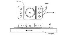
提案された解決方法のうちの1つは、液体供給システムのためのものであって、基板の局部領域上、および投影システムの最終素子と基板との間だけに液体を供給する方法である(基板は、一般的に、投影システムの最終素子よりも広い表面積を有する)。引用によりその全文を本明細書に援用するものとするPCT特許出願第WO99/49504号に、このような配置を行うために提案された1つの方法が開示されている。図2および図3に示すように、液体は少なくとも1つの入口INにより基板上に供給されるが、この供給は好適には最終素子に対する基板の運動方向に沿って行うことが好ましく、液体は投影システムの下を通過した後で少なくとも1つの出口OUTから流出する。すなわち、基板が素子の下で−X方向に走査されると、素子の+X側で液体が供給され、−X側に移動する。図2は、液体が入り口INを通して供給され、低圧源に接続している出口OUTにより素子の他方の側に移動する装置の略図である。図2においては、液体は、最終素子に対して基板の運動方向に沿って供給されるが、必ずしもこのようにする必要はない。最終素子の周囲に種々の方向を向けて、種々の数の入り口および出口を位置させることができる。図3はその一例を示す。この例の場合には、最終素子の周囲の規則的なパターンのどちらかの側に、1つの出口を有する4組の入り口が設けられている。 One of the proposed solutions is for a liquid supply system, which supplies liquid only on a local area of the substrate and between the final element of the projection system and the substrate ( The substrate generally has a larger surface area than the final element of the projection system). One method proposed for making such an arrangement is disclosed in PCT patent application WO 99/49504, which is incorporated herein by reference in its entirety. As shown in FIGS. 2 and 3, the liquid is supplied onto the substrate by at least one inlet IN, but this supply is preferably done along the direction of movement of the substrate relative to the final element, and the liquid is projected. After passing under the system, it flows out of at least one outlet OUT. That is, when the substrate is scanned in the −X direction under the element, liquid is supplied on the + X side of the element and moves to the −X side. FIG. 2 is a schematic diagram of an apparatus in which liquid is supplied through an inlet IN and travels to the other side of the element by an outlet OUT connected to a low pressure source. In FIG. 2, the liquid is supplied along the direction of movement of the substrate relative to the final element, but this need not necessarily be the case. Different numbers of inlets and outlets can be located in different directions around the final element. FIG. 3 shows an example. In this example, there are four sets of inlets with one outlet on either side of the regular pattern around the final element.
本発明の浸漬リソグラフィ装置の場合には、浸漬液の除去は、通常、二相流、すなわち周囲ガス(例えば、空気)または浸漬液を閉じ込めるために使用しているガス・シールからのガスを含む浸漬液の混合物を含む。このような二相流は安定性が非常に低く、特に浸漬液を閉じ込めるために、またはすべての液体を確実に収集する目的で、強力なガス流を生成するために大きな圧力差を使用した場合には、それによる振動は望ましいものではない。また、高圧ガス流は、基板上に残っている液体を蒸発により乾燥し、熱勾配を引き起こす恐れもある。干渉計ビームの通路に流れ込むガス流も、基板テーブルの位置の測定精度に影響を与える恐れがある。何故なら、干渉計は、温度、圧力および湿度の変化が引き起こすような干渉計ビームの通路内のガスの屈折率の変化に非常に敏感であるからである。 In the case of the immersion lithographic apparatus of the present invention, the removal of the immersion liquid typically involves a two-phase flow, ie the ambient gas (eg air) or gas from the gas seal used to contain the immersion liquid. Contains a mixture of immersion liquids. Such two-phase flow is very unstable, especially when using large pressure differentials to generate a strong gas flow, in order to confine immersion liquid or to collect all liquids reliably For this reason, the vibration caused by it is not desirable. In addition, the high-pressure gas flow may dry the liquid remaining on the substrate by evaporation and cause a thermal gradient. The gas flow that flows into the path of the interferometer beam can also affect the measurement accuracy of the position of the substrate table. This is because the interferometer is very sensitive to changes in the refractive index of the gas in the path of the interferometer beam as caused by changes in temperature, pressure and humidity.
それ故、例えば、基板の近くから液体を効果的に除去し、有意な振動および他の外乱を起こさない装置があれば有利である。 Thus, for example, it would be advantageous to have a device that effectively removes liquid from the vicinity of the substrate and does not cause significant vibrations and other disturbances.
ある態様によれば、本発明は、投影システムを使用し、投影システムと基板との間の空間に液体を供給するように配置される液体供給システムを有する、基板上にパターニング機器からパターンを投影するように配置されるリソグラフィ投影装置を提供する。このリソグラフィ投影装置は液体除去システムを備え、該液体除去システムは、
液体を含んでいる容積に隣接する開放端部を有するコンジット(導管)と、
コンジットの端部と容積との間の多孔性部材と、
多孔性部材の両端に圧力差を生じるように配置される吸込装置と
を含む。According to one aspect, the present invention uses a projection system to project a pattern from a patterning device onto a substrate having a liquid supply system arranged to supply liquid to a space between the projection system and the substrate. A lithographic projection apparatus arranged to do so is provided. The lithographic projection apparatus comprises a liquid removal system, the liquid removal system comprising:
A conduit having an open end adjacent to the volume containing the liquid;
A porous member between the end of the conduit and the volume;
And a suction device arranged to create a pressure difference at both ends of the porous member.
ある態様によれば、本発明はデバイス製造方法を提供する。このデバイス製造方法は、
投影システムを用いて液体を通して基板上にパターン化した放射線のビームを投影する段階と、
容積に少なくとも一部が隣接している多孔性部材の両端に圧力差を供給することにより上記容積から液体を除去する段階とを含む。According to an aspect, the present invention provides a device manufacturing method. This device manufacturing method
Projecting a patterned beam of radiation through a liquid onto a substrate using a projection system;
Removing liquid from the volume by supplying a pressure differential across the porous member that is at least partially adjacent to the volume.
添付の略図を参照しながら本発明の実施形態について以下に説明するが、これは単に例示としてのものに過ぎない。図面中、対応する参照符号は対応する部材を示す。 Embodiments of the present invention are described below with reference to the accompanying schematic drawings, which are merely exemplary. Corresponding reference characters indicate corresponding parts throughout the drawings.
図1は、本発明のある実施例によるリソグラフィ装置の略図である。この装置は、
放射線ビームPB(例えば、UV放射線またはDUV放射線)を調整するように構成されている照明システム(照明装置)ILと、
パターニング機器(例えば、マスク)MAを支持するように作られていて、いくつかのパラメータによりパターニング機器を正確に位置決めするように構成されている第1の位置決め装置PMに接続している支持構造(例えば、マスク・テーブル)MTと、
基板(例えば、レジストで被覆されたウェハ)Wを保持するように作られていて、いくつかのパラメータにより基板を正確に位置決めするように構成されている第2の位置決め装置PWに接続している基板テーブル(例えば、ウェハ・テーブル)WTと、
基板Wの目標部分C(例えば、1つまたは複数のダイを備えている)上にパターニング機器MAにより、放射線ビームPBに与えるパターンを投影するように構成されている投影システム(例えば、屈折投影レンズ・システム)PLとを備える。FIG. 1 schematically depicts a lithographic apparatus according to an embodiment of the invention. This device
An illumination system (illuminator) IL configured to condition a radiation beam PB (eg, UV radiation or DUV radiation);
A support structure (such as a mask) MA, which is made to support the patterning device (eg, mask) MA and connected to a first positioning device PM that is configured to accurately position the patterning device according to several parameters ( For example, mask table) MT,
Connected to a second positioning device PW that is configured to hold a substrate (eg, a resist-coated wafer) W and is configured to accurately position the substrate according to several parameters. A substrate table (eg, a wafer table) WT;
A projection system (eg, a refractive projection lens) configured to project a pattern imparted to the radiation beam PB by the patterning device MA onto a target portion C (eg, comprising one or more dies) of the substrate W. -System) with PL.
照明システムは、放射線をある方向に向け、整形し、または制御するための屈折、反射、磁気、電磁気、静電または他のタイプの光学構成要素、またはこれらの任意の組合わせのような種々のタイプの光学構成要素を含むことができる。 The illumination system can be used in a variety of ways, such as refraction, reflection, magnetic, electromagnetic, electrostatic or other types of optical components, or any combination thereof to direct, shape or control radiation. Types of optical components can be included.
支持構造は支持する、すなわち、パターニング機器の重量を支える。支持構造は、パターニング機器の向き、リソグラフィ装置の設計、および例えば、パターニング機器が真空環境内で保持されるのかどうかというような他の条件に依存する方法でパターニング機器を保持する。支持構造は、パターニング機器を保持するために、機械的、真空、静電または他の締付け技術を使用することができる。支持構造は、例えば、必要に応じて固定または移動することができるフレームまたはテーブルであってもよい。支持構造は、例えば、投影システムに対して、パターニング機器を所望の位置に確実に位置させることができる。「レチクル」または「マスク」という用語が本明細書内のどこかで使用されている場合には、もっと一般的な用語である「パターニング機器」と同じものであると見なすことができる。 The support structure supports, ie bears the weight of the patterning device. The support structure holds the patterning device in a manner that depends on the orientation of the patterning device, the design of the lithographic apparatus, and other conditions, such as for example whether or not the patterning device is held in a vacuum environment. The support structure can use mechanical, vacuum, electrostatic or other clamping techniques to hold the patterning device. The support structure may be, for example, a frame or table that can be fixed or moved as required. The support structure may ensure that the patterning device is at a desired position, for example with respect to the projection system. Any use of the terms “reticle” or “mask” herein may be considered the same as the more general term “patterning device”.
本明細書で使用する「パターニング機器」という用語は、放射線ビームを、基板の目標部分にパターンを生成するようなその断面図のパターンの形にするために使用することができる任意の機器を指すものと広義に解釈すべきである。放射線ビームに与えられたパターンは、例えば、パターンが位相シフト・フィーチャまたはいわゆる補助フィーチャを含んでいる場合には、基板の目標部分の所望のパターンに正確に対応しない場合があることに留意されたい。一般的に、放射線ビームに与えられたパターンは、集積回路のような目標部分で生成されるデバイスの特定の機能層に対応する。 As used herein, the term “patterning device” refers to any device that can be used to shape a radiation beam into a pattern of its cross-sectional view that produces a pattern on a target portion of a substrate. It should be interpreted broadly as a thing. Note that the pattern imparted to the radiation beam may not exactly correspond to the desired pattern of the target portion of the substrate, for example if the pattern includes phase shift features or so-called auxiliary features. . In general, the pattern imparted to the radiation beam will correspond to a particular functional layer in a device being created in the target portion, such as an integrated circuit.
パターニング機器は透過性のものであっても反射性のものであってもよい。パターニング機器の例としては、マスク、プログラマブル・ミラー・アレイ、およびプログラマブルLCDパネル等がある。マスクはリソグラフィで周知のものであり、2進交互位相シフトおよび減衰位相シフトおよび種々のハイブリッド・マスク・タイプのようなマスク・タイプを含む。プログラマブル・ミラー・アレイの一例は、異なる方向に入射放射線ビームを反射するように、それぞれを個々に傾斜させることができる小さなミラーのマトリックス配置を使用する。傾斜したミラーは、ミラー・マトリックスにより反射した放射線ビームをあるパターンの形にする。 The patterning device may be transmissive or reflective. Examples of patterning equipment include masks, programmable mirror arrays, and programmable LCD panels. Masks are well known in lithography and include mask types such as binary alternating phase shift and attenuated phase shift and various hybrid mask types. One example of a programmable mirror array uses a matrix arrangement of small mirrors that can each be individually tilted to reflect an incident radiation beam in different directions. The tilted mirror shapes the radiation beam reflected by the mirror matrix into a pattern.
本明細書で使用する「投影システム」という用語は、使用する露光放射線、または浸漬液の使用または真空の使用のような他の要因に適している屈折光学システム、反射光学システム、反射屈折光学システム、磁気光学システム、電磁光学システムおよび静電光学システムまたはこれらの任意の組合わせを含む任意のタイプの投影システムを含むものとして広義に解釈すべきである。本明細書内のどこかで「投影レンズ」という用語が使用されている場合には、もっと一般的な用語である「投影システム」と同じものであると見なすことができる。 As used herein, the term “projection system” refers to a refractive optical system, a reflective optical system, a catadioptric optical system that is suitable for the exposure radiation used, or other factors such as the use of immersion liquid or the use of vacuum. Should be broadly construed to include any type of projection system, including magneto-optical systems, electromagnetic optical systems and electrostatic optical systems or any combination thereof. Any use of the term “projection lens” anywhere in this specification can be considered as the same as the more general term “projection system”.
本明細書で説明する場合には、装置は、透過性タイプのもの(例えば、透過性マスクを使用する)である。別の方法としては、装置は反射性タイプのもの(例えば、上記タイプのプログラマブル・ミラー・アレイを使用する、または反射性マスクを使用する)であってもよい。 As described herein, the apparatus is of a transmissive type (eg, using a transmissive mask). Alternatively, the device may be of a reflective type (eg, using a programmable mirror array of the type described above or using a reflective mask).
リソグラフィ装置は、2つ(二重ステージ)またはもっと多くの基板テーブル(および/または2つ以上のマスク・テーブル)を有するタイプであってもよい。このような「多重ステージ」機械の場合には、追加のテーブルを並列に使用することができ、または準備工程を、1つまたは複数の他のテーブルを露光に使用しながら、1つまたは複数のテーブル上で実行することができる。 The lithographic apparatus may be of a type having two (dual stage) or more substrate tables (and / or two or more mask tables). In the case of such a “multi-stage” machine, additional tables can be used in parallel, or one or more preparatory steps can be used while using one or more other tables for exposure. Can be run on a table.
図1を参照すると、照明装置ILは、放射線源SOから放射線ビームを受光する。この放射線源およびリソグラフィ装置は、例えば、放射線源がエキシマ・レーザの場合のように、別々の構成であってもよい。このような場合、放射線源は、リソグラフィ装置の一部を形成するものとは見なされず、放射ビームは、例えば、適当な方向づけミラーおよび/またはビーム・エクスパンダを備えるビーム供給システムBDの助けを借りて、放射線源SOから照明装置ILに通過する。他の場合、放射線源は、例えば、放射線源が水銀ランプである場合のように、リソグラフィ装置の一部であってもよい。放射線源SOと照明装置ILは、必要な場合には、ビーム供給システムBDと一緒に放射システムと呼ぶ場合もある。 Referring to FIG. 1, the illuminator IL receives a radiation beam from a radiation source SO. The radiation source and the lithographic apparatus may be of different configurations, for example when the radiation source is an excimer laser. In such a case, the radiation source is not considered to form part of the lithographic apparatus, and the radiation beam is assisted, for example, by a beam delivery system BD with suitable directing mirrors and / or beam expanders. And passes from the radiation source SO to the illumination device IL. In other cases the radiation source may be part of the lithographic apparatus, for example when the radiation source is a mercury lamp. The radiation source SO and the illumination device IL may be referred to as a radiation system together with the beam supply system BD, if necessary.
照明装置ILは、放射線ビームの角度輝度分布を調整するための調整手段AMを備えることができる。通常、照明装置の瞳面内の輝度分布の少なくとも外部および/または内部半径範囲(通常、それぞれσアウタおよびσインナと呼ばれる)を調整することができる。さらに、照明装置ILは、インテグレータINおよびコンデンサCOのような種々のタイプの他の構成要素を備えることができる。照明装置は、その断面で所望の均一性および輝度分布を達成する目的で、放射線ビームを調整するために使用することができる。 The illuminating device IL may include an adjusting unit AM for adjusting the angular luminance distribution of the radiation beam. Usually, at least the outer and / or inner radius range (usually called σ outer and σ inner, respectively) of the luminance distribution in the pupil plane of the illuminator can be adjusted. Furthermore, the illuminator IL may comprise various other types of components such as an integrator IN and a capacitor CO. The illuminator can be used to condition the radiation beam in order to achieve the desired uniformity and brightness distribution in its cross section.
放射線ビームPBは、支持構造(例えば、マスク・テーブルMT)上に保持されているパターニング機器(例えば、マスクMA)上に入射し、パターニング機器によりパターン化される。マスクMAを横切った後で、放射線ビームPBは投影システムPLを通過し、投影システムPLはビームの焦点を基板Wの目標部分C上に結ぶ。以下にさらに詳細に説明する浸漬フードIHは、投影システムPLの最終素子と基板Wとの間の空間に浸漬液を供給する。 The radiation beam PB is incident on the patterning device (eg, mask MA), which is held on the support structure (eg, mask table MT), and is patterned by the patterning device. After traversing the mask MA, the radiation beam PB passes through the projection system PL, which focuses the beam on the target portion C of the substrate W. The immersion hood IH described in more detail below supplies immersion liquid to the space between the final element of the projection system PL and the substrate W.
第2の位置決め装置PWおよび位置センサIF(例えば、干渉計装置、リニア・エンコーダまたは容量性センサ)により、例えば、放射線ビームPBの通路内の異なる目標部分Cを位置決めするために、基板テーブルWTを正確に移動することができる。同様に、第1の位置決め装置PMおよびもう1つの位置センサ(図1に明示的に示されていない)を、例えば、マスク・ライブラリからの機械的検索の後、または走査中に、放射線ビームPBの通路に対してマスクMAを正確に位置決めするために使用することができる。一般的に、マスク・テーブルMTは、第1の位置決め装置PMの一部を形成しているロング・ストローク・モジュール(粗動位置決め)およびショート・ストローク・モジュール(微動位置決め)により移動させることができる。同様に、基板テーブルWTは、第2の位置決め装置PWの一部を形成しているロング・ストローク・モジュールおよびショート・ストローク・モジュールにより移動させることができる。ステッパの場合には(スキャナとは反対に)、マスク・テーブルMTをショート・ストローク・アクチュエータだけに接続することもできるし、または固定することもできる。マスクMAおよび基板Wは、マスク・アラインメント・マークM1、M2および基板アラインメント・マークP1、P2により整合することができる。図に示すように、基板アラインメント・マークは、専用の目標部分を占めているが、これらのマークは目標部分(スクライブ・レーン・アラインメント・マークと呼ばれる)間の空間内に位置させることもできる。同様に、マスクMA上に2つ以上のダイが位置している場合には、マスク・アラインメント・マークをダイの間に位置させることができる。 The second positioning device PW and the position sensor IF (e.g. interferometer device, linear encoder or capacitive sensor) are used to position the substrate table WT, e.g. for positioning different target portions C in the path of the radiation beam PB. It can move accurately. Similarly, a first positioner PM and another position sensor (not explicitly shown in FIG. 1) are connected to the radiation beam PB, for example after mechanical retrieval from a mask library or during a scan. Can be used to accurately position the mask MA with respect to the passage. In general, the mask table MT can be moved by a long stroke module (coarse positioning) and a short stroke module (fine positioning) forming part of the first positioning device PM. . Similarly, the substrate table WT can be moved by a long stroke module and a short stroke module forming part of the second positioning device PW. In the case of a stepper (as opposed to a scanner), the mask table MT can be connected only to a short stroke actuator or can be fixed. Mask MA and substrate W may be aligned by mask alignment marks M1, M2 and substrate alignment marks P1, P2. As shown, the substrate alignment marks occupy dedicated target portions, but these marks can also be located in the space between the target portions (referred to as scribe lane alignment marks). Similarly, if more than one die is located on the mask MA, a mask alignment mark can be located between the dies.
図の装置は下記のモードのうちの少なくとも1つで使用することができる。 The depicted apparatus can be used in at least one of the following modes:
1.ステップ・モードの場合には、マスク・テーブルMTおよび基板テーブルWTは本質的に固定されていて、一方、投影ビームに与えられた全パターンが、1回で(すなわち、1回の静的露光で)目標部分C上に投影される。基板テーブルWTは、次に、Xおよび/またはY方向に動かされ、そのため異なる目標部分Cを露光することができる。ステップ・モードの場合には、露光フィールドの最大サイズにより1回の静的露光で画像形成される目標部分Cのサイズが制限される。1. In step mode, the mask table MT and the substrate table WT are essentially fixed, while the entire pattern imparted to the projection beam is one time (ie, with one static exposure). ) Projected onto the target portion C. The substrate table WT is then moved in the X and / or Y direction so that a different target portion C can be exposed. In the step mode, the size of the target portion C to be imaged by one static exposure is limited by the maximum size of the exposure field.
2.走査モードの場合、マスク・テーブルMTおよび基板テーブルWTは同期状態で走査され、一方、投影ビームに与えられたパターンが、目標部分C上に投影される(すなわち、1回の動的露光)。マスク・テーブルMTに対する基板テーブルWTの速度および方向は、拡大(縮小)および投影システムPLの画像の逆特性により決定することができる。走査モードの場合には、露光フィールドの最大サイズにより1回の動的露光の際の目標部分の(走査方向でない方向の)幅が制限され、一方、走査運動の長さにより目標部分の(走査方向の)高さが決まる。2. In the scanning mode, the mask table MT and the substrate table WT are scanned in synchronization, while the pattern imparted to the projection beam is projected onto the target portion C (ie, one dynamic exposure). The speed and direction of the substrate table WT relative to the mask table MT can be determined by the enlargement (reduction) and the inverse characteristics of the image of the projection system PL. In the scanning mode, the maximum size of the exposure field limits the width of the target portion (in the direction other than the scanning direction) during one dynamic exposure, while the length of the scanning motion (scanning the target portion). The height is determined.
3.他のモードの場合、マスク・テーブルMTは、プログラマブル・パターニング機器を保持する本質的に固定状態に維持され、基板テーブルWTは、放射ビームに与えられたパターンの形が目標部分C上に投影されている間に移動または走査される。このモードの場合、通常、パルス放射線源が使用され、プログラマブル・パターニング機器が、基板テーブルWTの各運動の後で、または走査中の連続放射パルスの間に必要に応じて更新される。この動作モードは、上記タイプのプログラマブル・ミラー・アレイのようなプログラマブル・パターニング機器を使用し、マスクを使用しないリソグラフィに容易に適用することができる。 3. In other modes, the mask table MT is kept essentially stationary holding the programmable patterning device, and the substrate table WT is projected onto the target portion C in the form of the pattern imparted to the radiation beam. Moved or scanned while In this mode, a pulsed radiation source is typically used and the programmable patterning equipment is updated as necessary after each movement of the substrate table WT or during successive radiation pulses during scanning. This mode of operation can be readily applied to lithography without a mask using programmable patterning equipment such as a programmable mirror array of the type described above.
上記の使用モードの組合わせおよび/または変更したもの、または全然異なる使用モードを使用することもできる。 Combinations and / or modifications of the above usage modes or entirely different usage modes may also be used.
図4は、局在化液体供給システムによるもう1つの浸漬リソグラフィ解決方法を示す。液体は、投影システムPLのどちらかの側上の2つの溝入口INを通して供給され、入口INの外側に半径方向に配置されている複数の個々の出口OUTを通して除去される。入り口INおよび出口OUTは、その中央に孔部を有し、投影ビームが投影される1つの平面内に配置することができる。液体は投影システムPLの一方の側上の1つの溝入口INを通して供給され、投影システムPLの他方の側上の複数の個々の出口OUTを通して除去され、投影システムPLと基板Wとの間に液体の薄いフィルムの流れを形成する。入口INおよび出口OUTを使用するための組合わせの選択は、基板Wの運動方向により異なる(入口INおよび出口OUTの他の組合わせは作動しない)。 FIG. 4 shows another immersion lithography solution with a localized liquid supply system. Liquid is supplied through two groove inlets IN on either side of the projection system PL and removed through a plurality of individual outlets OUT arranged radially outside the inlet IN. The inlet IN and the outlet OUT have a hole in the center thereof, and can be arranged in one plane on which the projection beam is projected. Liquid is supplied through one groove inlet IN on one side of the projection system PL, removed through a plurality of individual outlets OUT on the other side of the projection system PL, and liquid between the projection system PL and the substrate W. Form a thin film stream. The choice of combination for using the inlet IN and outlet OUT depends on the direction of motion of the substrate W (other combinations of inlet IN and outlet OUT do not work).
今までに提案された局在化液体供給システム解決方法によるもう1つの浸漬リソグラフィの解決方法は、投影システムの最終素子と基板テーブルとの間の空間の境界の少なくとも一部に沿って延びるシール部材を含む液体供給システムを提供する方法である。図5はこのような解決方法を示す。シール部材は、XY面内の投影システムに対してほぼ固定されているが、Z方向(光軸の方向)にある程度相対運動を行うことができる。シールはシール部材と基板の表面との間に生成される。 Another immersion lithography solution according to the previously proposed localized liquid supply system solution is a seal member extending along at least part of the boundary of the space between the final element of the projection system and the substrate table A liquid supply system comprising: FIG. 5 shows such a solution. The seal member is substantially fixed with respect to the projection system in the XY plane, but can make a relative movement to some extent in the Z direction (direction of the optical axis). A seal is created between the seal member and the surface of the substrate.
図5を参照すると、リザーバ10は、投影システムの画像フィールドの周囲の基板に対して接点のないシールを形成し、そのため液体が閉じ込められ、基板表面と投影システムの最終素子との間の空間を満たす。リザーバは、投影システムPLの最終素子の下および周囲に位置するシール部材12により形成される。液体は投影システムの下の空間およびシール部材12内の空間に入る。シール部材12は、投影システムの最終素子の少し上を延びていて、液体レベルは、最終素子の上に上昇し、そのため液体のバッファが形成される。シール部材12は、内周縁部を有し、この内周縁部は、ある実施例の場合には、上端部のところで投影システムまたはその最終素子の形状と密着していて、例えば丸い形をしていてもよい。底部のところで、内周縁部は、例えば長方形の画像フィールドの形状に密着している。しかし、必ずしもそうである必要はない。 Referring to FIG. 5, the
液体は、シール部材12の底部と基板Wの表面との間のガス・シール16によりリザーバ内に閉じ込められる。ガス・シールは、例えば空気または合成空気のようなガスにより形成されるが、ある実施例の場合には、N2(窒素ガス)または他の不活性ガスが、圧力により入り口15を通してシール部材12と基板との間のギャップ内に導入され、第1の出口14を通して抽出される。ガスの入り口15上の過度の圧力、第1の出口14上の真空レベルおよびギャップの幾何学的形状は、液体を閉じ込める内側への高速ガス流ができるように配置されている。引用によりその全文を本明細書に援用するものとする米国特許出願第10/705,783号にこのようなシステムが開示されている。 The liquid is confined in the reservoir by a
図6および図6の一部の拡大図である図7は、本発明のある実施例による液体除去装置20を示す。液体除去装置20は、若干低い圧力pcに維持されていて、浸漬液で満たされているチャンバを備える。チャンバの下面は、例えば、5〜50μmの範囲内の直径dholeを有する多数の小さな孔部を有する薄板21により形成されていて、例えば、基板Wの表面のような液体が除去される表面の上50〜300μmの範囲内の高さhgapのところに維持される。ある実施形態の場合には、有孔板21は少なくとも若干親水性である。すなわち、例えば、水のような浸漬液に対して90度未満の接触角を有する。 FIG. 7, which is an enlarged view of a portion of FIGS. 6 and 6, shows a
低圧pcは、有孔板21内の孔部内に形成されたメニスカス22が、ガスが液体除去装置のチャンバ内に下降するのを防止するようなレベルの圧力である。しかし、板21が基板W上の液体と接触すると、流れを制限するメニスカスがなくなり、液体は液体除去装置のチャンバ内に自由に流入することができる。このような装置は、基板Wの表面から大部分の液体を除去することができるが、図に示すように、液体の薄いフィルムは残る。 The low pressure pc is a pressure at such a level that the
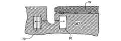
液体の除去を改善し、または最大にするために、有孔板21はできるだけ薄くなければならないし、液体内の圧力pgapとチャンバ内の圧力pcとの間の圧力差はできるだけ大きくなければならないが、一方、pcとギャップ内のガスの圧力Pairの間の圧力差は十分に低く、有意な量のガスが液体除去装置20内に下降するのを防止できなければならない。液体除去装置内へのガスの下降はいつでも防止できるものではないが、有孔板は、振動を起こすかもしれない大きな均一でない流れを防止する。電鋳、フォトエッチングおよび/またはレーザカットで作ったマイクロ篩を、板21として使用することができる。オランダのEerbeekのStork Veco B.V.社から適当な篩が市販されている。孔部のサイズが使用中にかかる圧力差でメニスカスを維持するのに適当な大きさである限りは、他の多孔板または多孔性材料の固体ブロックも使用することができる。 To improve or maximize liquid removal, the
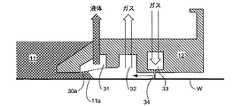
図8は、本発明の特定の実施例による浸漬フードIHのシール部材12が内蔵する液体除去装置である。図8は、投影システムPL(図8に図示せず)の露光フィールドの少なくとも一部を囲むリング(本明細書で使用する場合には、円形でも、長方形でもまたは任意の他の形をしていてもよい)を形成しているシール部材12の一方の側面の断面図である。この実施例の場合には、液体除去装置20は、シール部材12の下面の最も内側の縁部近くのリングの形をしているチャンバ31により形成されている。チャンバ31の下面は、すでに説明したように、多孔板30により形成されている。リング状のチャンバ31は、チャンバから液体を除去し、所望の低圧を維持するために、適当な1台のポンプまたは複数のポンプに接続している。使用中、チャンバ31は液体で満たされるが、図面を分かりやすくするためにこの図では空になっている。 FIG. 8 is a liquid removal device built into the sealing
リング状のチャンバ31の外部には、ガス抽出リング32およびガス供給リング33が位置する。ガス供給リング33は、その下部に狭いスリットを有し、例えば、空気、人工の空気またはフラッシング・ガスのようなガスを、スリットから流出するガスがガス・ナイフ34を形成するような圧力で供給する。ガス・ナイフを形成しているガスは、ガス抽出リング32に接続している適当な真空ポンプにより抽出され、そのため結果としてのガス流が、残った液体を内側に押して、そこで液体は、浸漬液の蒸気および/または液体の小滴に耐えることができなければならない液体除去装置および/または真空ポンプにより除去することができる。しかし、大部分の液体は液体除去装置20により除去されるので、真空システムを介して除去された少量の液体は、振動を起こす恐れがある不安定な流れ
を発生しない。A
本明細書においては、チャンバ31、ガス抽出リング32、ガス供給リング33、および他のリングをリングと呼ぶが、これらのリングは露光フィールドを囲んでいる必要もないし、完全なリングでなくてもよい。ある実施例の場合には、このような入口および出口は、単に円形であっても、長方形であっても、例えば、図2、図3および図4に示すように、露光フィールドの1つまたは複数の側面に沿って部分的に延びる他のタイプの素子であってもよい。 In this specification, the
図8の装置の場合には、ガス・ナイフを形成しているガスの大部分は、ガス抽出リング32を通して抽出されるが、ガスの一部は浸漬フードの周囲の環境内に流れることができ、干渉計の位置測定システムIFを擾乱する恐れがある。このような擾乱は、図8Aに示すように、ガス・ナイフの外部に追加のガス抽出リング35を設置することにより防止することができる。 In the case of the apparatus of FIG. 8, most of the gas forming the gas knife is extracted through the
この実施例の場合には、液体除去システムは、基板Wまたは基板テーブルWTの表面の上50〜300μmの高さのところで、全部でなくても大部分の浸漬液を除去することができるので、浸漬液を閉じ込めるために気体軸受を使用する場合と比較すると、シール部材の垂直位置に対する厄介な要件が低減する。このことは、シール部材を、もっと簡単な作動および制御システムに垂直に設置することができることを意味する。このことは、また、基板テーブルおよび基板の平面度に対する要件が低減し、基板テーブルWTの上表面に設置しなければならないセンサのような機器の組立てがより簡単になることも意味する。 In this embodiment, the liquid removal system can remove most if not all of the immersion liquid at a height of 50-300 μm above the surface of the substrate W or substrate table WT. Compared to using a gas bearing to contain the immersion liquid, the cumbersome requirements for the vertical position of the seal member are reduced. This means that the seal member can be installed vertically in a simpler actuation and control system. This also means that the requirements for the flatness of the substrate table and substrate are reduced, and the assembly of equipment such as sensors that must be installed on the upper surface of the substrate table WT is made easier.
蒸発によらないで大部分の液体を除去できるということは、また、温度勾配が緩やかになり、いわゆる印刷誤差を起こす恐れがある基板の熱による変形を避けることができることを意味する。例えば、約100〜500mbarの圧力降下および約20〜200リットル/分の流速と組合わせて、約50〜75%の相対湿度でガス・ナイフ内で湿ったガスを使用することにより、蒸発をさらに最小限度に低減することもできる。 The fact that most of the liquid can be removed without evaporation means that the temperature gradient becomes gentle, and deformation of the substrate due to heat that may cause a so-called printing error can be avoided. For example, by using a moist gas in a gas knife at a relative humidity of about 50-75% in combination with a pressure drop of about 100-500 mbar and a flow rate of about 20-200 liters / minute further evaporates. It can also be reduced to a minimum.
図9〜図11は、本発明のこの実施例の変形例を示す。これらの変形例は、多孔板30の形状に関する点を除けば、上記実施例と同じである。 9-11 illustrate a variation of this embodiment of the present invention. These modifications are the same as the above embodiment except for the point related to the shape of the
図9に示すように、多孔板30aは、少しの角度をつけて設置することができ、そのためこの板は外部の方が高い。露光フィールドの中心から遠ざかるにつれて増大する多孔板30aと基板Wまたは基板テーブルWT間のギャップは、メニスカス11aの形状を変化させ、液体内に浸漬する面積が多かれ少なかれ一定の幅を確実に有するのを助ける。 As shown in FIG. 9, the
図10および図11に示す変形例の場合には、鋭角のコーナー35は、鋭角のコーナーのところの表面張力により保持されるメニスカス11aの位置を制限するために使用される。鋭角のコーナーは、図10に示すように鈍角であってもよいし、図11に示すように直角であってもよい。ガス抽出リング32の形は必要に応じて調整することができる。 In the case of the variant shown in FIGS. 10 and 11, the
図12の実施例の場合には、別々のアクチュエータの代わりに、シール部材12の少なくとも一部を支持するために、液体軸受36を使用している。液体軸受または動圧軸受36は、周知の方法で液体供給チャンバ37に圧力下で供給される浸漬液により形成される。液体は、二相流を処理することができる適当なポンプ(図示せず)に接続している二相抽出チャンバ38を介して除去される。ガス・ナイフ34は、上記実施例と同じ方法で浸漬液を閉じ込める。
In the embodiment of FIG. 12, a
液体軸受36を使用することにより、シール部材12を基板Wまたは基板テーブルWTの上約50〜200μmの高さのところに維持することができ、すでに説明したように、制御および平面度に対する要件が低減される。同時に、二相抽出によりシール部材12内に形成しなければならないチャンバの数、およびシール部材に設置しなければならないホースの数が少なくてすむようになる。
By using the
流体軸受36を使用することにより、シール部材12を基板Wまたは基板テーブルWTの上約50〜200μmの高さのところに維持することができ、すでに説明したように、制御および平面度に対する要件が低減される。同時に、二相抽出によりシール部材12内に形成しなければならないチャンバの数、およびシール部材に設置しなければならないホースの数が少なくてすむようになる。 By using the
多孔板30は、その中へのガスおよび液体の流れを制御するために、二相抽出チャンバ38の底部を横切って設置されている。この板内の孔のサイズ、数および配置を適当に選択することにより、二相流が安定し、振動を起こす恐れがある不均一な流れが発生するのを避けることができる。この実施例でのように、マイクロ篩を板30として使用することができる。 A
上記実施例のところで説明したように、浸漬液11のメニスカスの位置を制御するために、傾斜または鋭角の縁部を多孔板30に設けることができる。この場合も、高い湿度によりすべての残留液体を除去することができ、大きな流れのガス・ナイフ34およびガス・ナイフの圧力もメニスカスの位置を制御するために使用することができる。 As described in the above embodiment, in order to control the position of the meniscus of the
本発明のこの実施例および他の実施例の場合には、浸漬液内に位置するシール部材の一部の形状は、シール部材12の垂直方向の運動を所望する程度減速するために調整することができる。より詳細に説明すると、狭い通路内に液体11を閉じ込めるシール部材の一部の幅Lda、すなわち面積は、所望の減速を行うことができるように選択することができる。減速の程度は、減速領域の面積、基板Wまたは基板テーブルWT上のその高さhda、浸漬液の密度ρ、およびその粘度ηにより決まる。減速をすることにより、例えば、不均一な液体の流れによる振動によるシール部材の位置の変動を低減することができる。 In this and other embodiments of the invention, the shape of the portion of the seal member located within the immersion liquid is adjusted to slow down the vertical movement of the
多孔板41は、また、図13に示すように、オーバーフロー・ドレン40内の流れを制御するためにも使用することができる。図13のオーバーフロー・ドレンは、本明細書で説明する本発明のすべての実施例で使用することができる。オーバーフロー・ドレンは、シール部材12の中心から比較的大きな半径のところのシール部材12の上表面に設置される。投影システムPLの最終素子と基板Wとの間の空間が浸漬液で溢れた場合には、過度の液体は、シール部材12の頂部上にまたドレン40内に流れ込む。ドレン40は、通常、液体で満たされていて、若干低い圧力に維持される。多孔板41は、ガスがオーバーフロー・ドレンに下降するのを防止するが、必要な場合には、液体は流出することができる。また、多孔板は、水平方向に対して小さな角度に設置することができる。 The
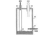
また、多孔性分離装置を、浸漬フードIHからの二相流を受け入れる液体ドレン・システム内に設置されているマニフォールド50で使用することもできる。図14に示すように、二相流51は、液体およびガスが分離されるマニフォールド・チャンバ51内に放出される。ガスは、適当な真空ポンプおよび圧力コントローラにより約−0.1bargの圧力に維持されているガス出口52によりマニフォールドの頂部から除去される。液体除去パイプ53は、マニフォールドの底部近くまで延びていて、多孔板54により閉ざされている。液体除去パイプ53は、例えば、約−0.5bargのような多孔板54の泡立ち点以下の圧力に維持される。この配置により、マニフォールド内の液体レベルがパイプ53の底部以下にたとえ下がっても、ガスはその中に流入しないで、浸漬フードIHに伝搬し擾乱を起こすかもしれないマニフォールド50の圧力の望ましくない変動を防止する。 The porous separator can also be used with a manifold 50 installed in a liquid drain system that accepts a two-phase flow from the immersion hood IH. As shown in FIG. 14, the two-
図15は、マニフォールドの変形例を示す。下記の点を除けば図14と同じこの変形例の場合には、マニフォールドはその周囲から熱的に絶縁されている。マニフォールドを通る真空の流れにより、浸漬液が蒸発し、冷却が行われる。マニフォールドを基準または計測フレームのようなリソグラフィ装置の感温部の近くにまたは熱的に接触状態に設置すると、このような冷却により望ましくない影響が起こる場合がある。 FIG. 15 shows a modification of the manifold. In the case of this variation, which is the same as in FIG. 14 except as noted below, the manifold is thermally insulated from its surroundings. The immersion liquid evaporates and cools by the flow of vacuum through the manifold. Such cooling may cause undesirable effects when the manifold is placed near a thermal part of a lithographic apparatus, such as a reference or metrology frame, or in thermal contact.
それ故、マニフォールドは、内部タンク50aと外部タンク50bの壁部間に例えば水のような温度が制御された液体の流れを含む内部タンク50aおよび外部タンク50bからなる二重壁タンクとして形成される。温度が制御された液体は、入り口55から流入し、出口56から流出する。一連のバッフル57が2つのタンクの壁部間の空間内に配置されていて液体が確実に停滞しないようにしている。二重壁のタンクによる断熱材を通して熱が伝導するのを防止するために、バッフルは内部タンクにも外部タンクにも接触していない。温度が制御された液体の流速は、外部タンク50bの温度偏差が確実に任意の近くの感温構成要素の制限内にあるように決定される。エア・ギャップまたは追加の断熱材も、好適には、外部タンクと任意の近くの感温構成要素間に設置することが好ましい。 Therefore, the manifold is formed as a double-walled tank consisting of an
図16は、本発明の実施例で使用することができる液体供給システム60を示す。この液体供給システムは、直列に例えば超純粋な液体のfab供給のような浸漬液源61と、定流制限器62と、可変流制限器63と、浸漬フードIHの直前に位置する外部タップ、可変流制限器65および定流制限器66を有する圧力調整器64とを備える。圧力調整器64用のパイロット・ラインは、可変流制限器65の下流に接続しているので、定流制限器66への入力は一定の圧力で供給され、そのため浸漬フードへの流れは定圧および定速となる。 FIG. 16 illustrates a
図17は、もう1つの液体供給システム60’を示す。この液体供給システムは、下記の点を除けばシステム60と同じである。調整器64および固定制限器66の代わりに、順方向圧力調整器67および逆方向圧力調整器68が設置されている。また、2つの圧力計69a、69bも設置されている。順方向圧力調整器67は、その下流の圧力を所定のレベルに維持し、逆方向圧力調整器はその上流の圧力を所定のレベルに維持する。両方の場合、流速は無関係である。それ故、可変流制限は、一定の上流圧力および一定の下流圧力で動作して不安定になるのを防止する。流速は、監視のために使用することもできる圧力センサ69a、69bにより、圧力調整器67、68および可変流制限器65が設定した圧力レベルを調整することにより調整することができる。 FIG. 17 shows another liquid supply system 60 '. This liquid supply system is the same as the
リソグラフィ装置においては、基板は、その主表面上に多数の小さな突起または隆起を有する直径が基板と同じ平らな板を備える基板ホルダ(よく突起板、隆起板またはチャックとも呼ばれる)により保持される。基板ホルダは、基板テーブル(ミラー・ブロック)の凹部内に位置していて、基板は基板ホルダの頂部上に置かれる。基板テーブルとホルダとの間の空間、およびホルダと基板との間の空間が真空になり、そのため基板およびホルダは、基板上の大気圧により正しい位置に固定される。基板テーブルの凹部は、基板サイズおよび設置のバラツキに対応するために、当然基板ホルダおよび基板よりも若干大きい。それ故、浸漬液を収集することができる狭い溝すなわちトレンチが基板の縁部の周囲に設けられている。溝すなわちトレンチ内に位置している場合には、液体は悪影響を及ばさないが、浸漬フード内の気体軸受またはガス・ナイフにより溝から吹きこぼれる場合がある。浸漬フードの下の液体メニスカスがそれによる基板または基板テーブル上の液滴と遭遇した場合、泡を発生する恐れがある。 In a lithographic apparatus, a substrate is held by a substrate holder (often referred to as a raised plate, raised plate or chuck) comprising a flat plate having the same diameter as the substrate with a number of small protrusions or raised portions on its main surface. The substrate holder is located in a recess in the substrate table (mirror block) and the substrate is placed on top of the substrate holder. The space between the substrate table and the holder and the space between the holder and the substrate are evacuated, so that the substrate and the holder are fixed in the correct position by the atmospheric pressure on the substrate. The concave portion of the substrate table is naturally slightly larger than the substrate holder and the substrate in order to accommodate variations in substrate size and installation. Therefore, there are narrow grooves or trenches around the edge of the substrate that can collect immersion liquid. When located in a groove or trench, the liquid does not adversely affect, but may be spilled from the groove by a gas bearing or gas knife in the immersion hood. If the liquid meniscus under the immersion hood encounters a droplet on the substrate or substrate table thereby, bubbles may be generated.
基板ホルダは、一般的に、ZerodurまたはULEのような熱膨張係数が低い材料からできている。いくつかのこのような材料は多孔性であり、その場合、表面の孔部は液体で満たされ、汚染物が孔部に入るのを防止する。しかし、基板ホルダの縁部および/または周辺領域の周囲の表面の孔部を液体で満たさないことが提案されている。この場合、基板ホルダを浸漬リソグラフィ装置で使用する場合には、溝に入る浸漬液は基板ホルダの孔部に入り、気体軸受またはガス・ナイフにより吹きこぼれない。基板ホルダが開いたセル状の構造を有している場合には、その孔部に入っている浸漬液は、基板およびホルダをテーブルに固定している真空システムにより除去することができる。 The substrate holder is generally made of a material with a low coefficient of thermal expansion, such as Zerodur or ULE. Some such materials are porous, in which case the surface pores are filled with liquid and prevent contaminants from entering the pores. However, it has been proposed that the edge of the substrate holder and / or the perforations on the surface around the peripheral area are not filled with liquid. In this case, when the substrate holder is used in an immersion lithography apparatus, the immersion liquid entering the groove enters the hole of the substrate holder and is not spilled by the gas bearing or the gas knife. When the substrate holder has an open cell structure, the immersion liquid in the hole can be removed by a vacuum system that fixes the substrate and the holder to the table.
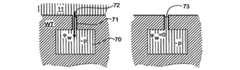
図18に示すように、親水性の壁部72を有する細い毛細管71を介して液体だけが抽出される容積に接続している抽出チャネル70は、例えば、水のような液体が適当な低い圧力pにより抽出されるが、液体が容積内に存在しない場合には、メニスカス73を、例えば空気のようなガスが進入するのを防止するように配置することができる。反対に、図19に示すように、疎水性の壁部82を有する毛細管81を介して容積に接続している抽出チャネル80は、例えば空気のようなガスを抽出するが、例えば、水のような液体が存在する場合には、メニスカス83はそれ以上の流れを防止する。これらの配置のために必要な低圧pの正確なレベルは、関連する液体およびガス、毛細管のサイズおよび毛細管の壁部への液体の接触角により異なる。しかし、幅0.05mmの毛細管の場合には、水または空気を選択的に抽出することができるようにするには、20mbarの低圧が適している。 As shown in FIG. 18, an
このタイプの抽出装置は、リソグラフィ装置の任意の所望の部分から液体またはガスを選択的に除去するために使用することができる。図20a〜dは、特に有利な使用方法を示す。この場合、液体抽出チャネル70およびガス抽出チャネル80は、両方とも、基板Wの縁部の周囲の基板テーブルWTのトレンチに接続している。基板の縁部が投影レンズの下に位置する場合、すなわちトレンチが液体で満たされている場合には、チャネル70は液体を抽出し、そのため液体は下方に流れる。これにより、例えば、不完全な充填により、トレンチ内に位置するすべての泡が下方に吸い取られる。これにより泡はある位置に送られ、そこでチャネル80を介してガスを抽出することができるが、泡はチャネル70には入らない。基板の縁部がもはや投影レンズの下に位置していない場合には、トレンチは急速に空になる。このようにして、泡の流出が画像形成の干渉するのが防止される。液体の流れとガスの流れとを分離することにより、振動を起こす恐れがある不安定な状況を避けることができ、蒸発による冷却効果を最小限度に低減することができる。 This type of extraction apparatus can be used to selectively remove liquids or gases from any desired portion of the lithographic apparatus. Figures 20a-d show a particularly advantageous method of use. In this case, the
欧州特許出願第03257072.3号に、ツインまたは二重ステージ浸漬リソグラフィ装置のアイデアが開示されている。このような装置は、基板を支持するための2つのテーブルを備える。浸漬液を使用しないで、第1の位置でテーブルにより平面度測定が行われ、浸漬液を使用して第2の位置でテーブルにより露光が行われる。別の方法としては、装置はテーブルを1つだけ有する。 European Patent Application No. 03257072.3 discloses the idea of a twin or double stage immersion lithography apparatus. Such an apparatus comprises two tables for supporting the substrate. Without using the immersion liquid, the flatness measurement is performed with the table at the first position, and the exposure is performed with the table at the second position using the immersion liquid. Alternatively, the device has only one table.
本明細書において、IC製造の際のリソグラフィ装置の使用について特に参照する場合があるが、本発明のリソグラフィ装置は、集積光学システム、磁気領域メモリ用の案内および検出パターン、フラットパネル・ディスプレイ、液晶ディスプレイ(LCD)、薄膜磁気ヘッド等の製造のような他の用途にも使用することができることを理解されたい。当業者であれば、このような別の用途の場合、本明細書で使用する「ウェハ」または「ダイ」という用語は、それぞれもっと一般的な用語である「基板」または「目標部分」と同義語であると見なすことができることを理解することができるだろう。本明細書における基板は、例えば、トラック(通常、基板にレジストの層を塗布し、露光したレジストを現像するツール)、計測ツールおよび/または検査ツールのような露光の前後で処理することができる。適用できる場合には、本明細書の開示を、上記および他の基板処理ツールに適用することができる。さらに、基板を、例えば、多層ICを形成するために2回以上処理することができる。そのため、本明細書で使用する基板という用語は、多重処理層をすでに含んでいる基板を意味する場合もある。 In this specification, reference may be made in particular to the use of a lithographic apparatus in the manufacture of ICs, but the lithographic apparatus of the present invention comprises an integrated optical system, guide and detection patterns for magnetic area memory, flat panel displays, liquid crystals It should be understood that it can also be used for other applications such as the manufacture of displays (LCDs), thin film magnetic heads and the like. Those skilled in the art will recognize that for such other applications, the terms “wafer” or “die” as used herein are synonymous with the more general terms “substrate” or “target portion”, respectively. You will understand that they can be considered words. The substrate herein can be processed before and after exposure, such as a track (usually a tool that applies a layer of resist to the substrate and develops the exposed resist), metrology tool and / or inspection tool. . Where applicable, the disclosure herein may be applied to these and other substrate processing tools. Further, the substrate can be processed more than once, for example, to form a multilayer IC. As such, the term substrate as used herein may refer to a substrate that already contains multiple processing layers.
本明細書で使用する「放射線」および「ビーム」という用語は、紫外線(UV)放射線(例えば、約365、248、193、157または126nmの波長を有する)を含むすべてのタイプの電磁放射線を含む。 As used herein, the terms “radiation” and “beam” include all types of electromagnetic radiation, including ultraviolet (UV) radiation (eg, having a wavelength of about 365, 248, 193, 157 or 126 nm). .
「レンズ」という用語は、前後関係からそう解釈できる場合には、屈折性および反射性光学構成要素を含む種々のタイプの光学構成要素のうちの任意のものまたは組合わせを意味する。 The term “lens” means any type or combination of various types of optical components, including refractive and reflective optical components, where such context can be interpreted.
今まで本発明の特定の実施例について説明してきたが、本発明は上記以外の方法でも実行することができることを理解することができるだろう。例えば、適用できる場合には、本発明は、上記方法を記述している機械読み取り可能命令の1つまたは複数のシーケンスを含むコンピュータ・プログラムの形をとることもできるし、またはその内部にこのようなコンピュータ・プログラムを記憶しているデータ記憶媒体(例えば、半導体メモリ、磁気または光ディスク)の形をとることもできる。 While specific embodiments of the present invention have been described above, it will be appreciated that the present invention can be practiced in other ways. For example, where applicable, the present invention may take the form of a computer program that includes one or more sequences of machine-readable instructions describing the above method, or such as within. It can also take the form of a data storage medium (eg, semiconductor memory, magnetic or optical disk) that stores various computer programs.
本発明は、任意の浸漬リソグラフィ装置、特に上記タイプを含むがこれに限定されない浸漬リソグラフィ装置に適用することができる。この装置で使用する浸漬液は、使用する露光放射線の所望の特性および波長により異なる組成を有することができる。193nmの露光波長の場合には、超純水または水をベースとする組成を使用することができ、そのため浸漬液は、場合により水と呼ばれ、親水性、疎水性、湿度等のような水に関連する用語を使用することができる。しかし、本発明の実施形態は、他のタイプの液体と一緒に使用することもでき、その場合には、このような水に関連する用語を、使用する浸漬液に関連する等価の用語に置き換えることができると考えられたい。 The present invention is applicable to any immersion lithographic apparatus, in particular an immersion lithographic apparatus including but not limited to the types described above. The immersion liquid used in this apparatus can have different compositions depending on the desired properties and wavelength of the exposure radiation used. In the case of an exposure wavelength of 193 nm, ultrapure water or a composition based on water can be used, so that the immersion liquid is sometimes referred to as water, and water such as hydrophilicity, hydrophobicity, humidity, etc. Terms related to can be used. However, embodiments of the present invention can also be used with other types of liquids, in which case such water related terms are replaced with equivalent terms related to the immersion liquid used. I want to think that I can do it.
上記説明は例示としてのものであって本発明を制限するものではない。それ故、当業者であれば、添付の特許請求の範囲の範囲から逸脱することなしに、上記発明を種々に修正することができることを理解することができるだろう。 The above description is illustrative and not restrictive. Thus, those skilled in the art will recognize that the invention can be variously modified without departing from the scope of the appended claims.
PB 放射線ビーム
IL 照明システム(照明装置)
MA パターニング機器
PM 第1の位置決め装置
MT 支持構造
W 基板
PW 第2の位置決め装置
WT 基板テーブル
C 目標部分
PL 投影システム
SO 放射線源
BD ビーム供給システム
AM 調整手段
IN インテグレータ
CO コンデンサ
IH 浸漬フード
IF 位置センサ
M1,M2 マスク・アラインメント・マーク
P1,P2 基板アラインメント・マーク
10 リザーバ
12 シール部材
14 第1の出口
15 入り口
20 液体除去装置
21 有孔板
22 メニスカス
30 多孔板
31 チャンバ
32 ガス抽出リング
33 ガス供給リング
34 ガス・ナイフ
35 コーナー
36液体軸受
37 液体供給チャンバ
38 二相抽出チャンバ
40 ドレン
41 多孔板
50 マニフォールド
50a 内部タンク
50b 外部タンク
51 二相流
52 ガス出口
53 液体除去パイプ
54 多孔板
55 入り口
56 出口
57 バッフル
60 液体供給システム
61 浸漬液源
62 定流制限器
63 可変流制限器
64 圧力調整器
65 可変流制限器
66 定流制限器
67 順方向圧力調整器
68 逆方向圧力調整器
69a,69b 圧力計
70 液体抽出チャネル
73 メニスカス
80 ガス抽出チャネル
81 毛細管
82 壁部
83 メニスカスPB radiation beam IL illumination system (illuminator)
MA patterning equipment PM first positioning device MT support structure W substrate PW second positioning device WT substrate table C target portion PL projection system SO radiation source BD beam supply system AM adjusting means IN integrator CO capacitor IH immersion hood IF position sensor M1 , M2 Mask alignment mark P1, P2
Claims (5)
Translated fromJapanese前記投影システムと、前記基板、前記基板テーブル、あるいはその両方との間の空間に液体を供給するように配置される液体供給システムと、
液体が存在する容積に隣接する開放端部を有するコンジットと、
前記コンジットの前記端部と前記容積との間の多孔性部材と、
前記多孔性部材の両端に圧力差を生じるように配置される吸込装置と、
前記空間の少なくとも一部を囲んでいる部材とを備え、
前記部材が、前記基板の表面から残留液体を除去するためのガス・ナイフを形成するように前記基板に面している表面に出口を有するガス供給回路と、入口を有するガス抽出回路とを備え、
前記コンジットが前記基板に面している前記部材の表面に凹部を画定し、前記多孔性部材が前記凹部を閉ざし、前記ガス・ナイフが前記凹部の半径方向外側に位置し、前記入口が前記凹部及び前記ガス・ナイフの間に位置している、装置。A lithographic projection apparatus arranged to project a pattern from a patterning device ontoa substratesupported by a substrate table using a projection system,
A liquid supply system arranged to supply liquid to a space between the projection system and the substrate, the substrate table, or both;
A conduit having an open end adjacent to the volume in which the liquid is present;
A porous member between the end of the conduit and the volume;
A suction device arranged to create a pressure difference across the porous member;
A member surrounding at least a part of the space,
The member comprises a gas supply circuit having an outlet on a surface facing the substrate and a gas extraction circuit having an inlet so as to form a gas knife for removing residual liquid from the surface of the substrate. ,
The conduit defines a recess in the surface of the member facing the substrate, the porous member closes the recess, the gas knife is located radially outward of the recess, and the inlet is the recess And a devicelocated between said gas knives .
投影システムを用いて液体を通して基板上に放射線のパターン化したビームを投影する段階と、
それを通して前記パターン化したビームが投影される前記液体を含む空間に隣接する容積から、少なくとも一部が前記容積に接しており且つ凹部を閉ざしている多孔性部材の両端に圧力差を供給することにより、液体を除去する段階であって、前記凹部が前記空間の少なくとも一部を囲んでいる部材の前記基板に面している表面に画定されている、該段階と、
前記基板の表面から残留液体を除去するためのガス・ナイフを形成するように前記基板に面している表面からガスを供給する段階であって、前記ガスが前記凹部の半径方向外側の位置に供給される、該段階と、
前記凹部と前記ガスが供給される前記位置との間の位置からガスを除去する段階とを含む方法。A device manufacturing method comprising:
Projecting a patterned beam of radiation through a liquid onto a substrate using a projection system;
From the volume beam the patterned throughit adjacent a space comprising the liquid to be projected, to supply the pressure differential across a porous member at least part ofwhich closes the and the recess is in contact withsaid volumeAccordingly,a step of removing theliquid, the recess is defined on the surface facing the substrate of the member surrounding at least a portion of said space, andsaidstep,
Supplying a gas from a surface facing the substrate to form a gas knife for removing residual liquid from the surface of the substrate, the gas being at a position radially outward of the recess. Provided, and
Removing gas from a position between the recess and the position to which the gas is supplied .
Applications Claiming Priority (2)
| Application Number | Priority Date | Filing Date | Title |
|---|---|---|---|
| US10/921,348US7701550B2 (en) | 2004-08-19 | 2004-08-19 | Lithographic apparatus and device manufacturing method |
| US10/921,348 | 2004-08-19 |
Related Parent Applications (1)
| Application Number | Title | Priority Date | Filing Date |
|---|---|---|---|
| JP2005237216ADivisionJP4456044B2 (en) | 2004-08-19 | 2005-08-18 | Lithographic apparatus and device manufacturing method |
Related Child Applications (2)
| Application Number | Title | Priority Date | Filing Date |
|---|---|---|---|
| JP2010116393ADivisionJP5023187B2 (en) | 2004-08-19 | 2010-05-20 | Lithographic apparatus |
| JP2010116426ADivisionJP5167307B2 (en) | 2004-08-19 | 2010-05-20 | Lithographic projection apparatus |
Publications (2)
| Publication Number | Publication Date |
|---|---|
| JP2009076951A JP2009076951A (en) | 2009-04-09 |
| JP4718619B2true JP4718619B2 (en) | 2011-07-06 |
Family
ID=35432522
Family Applications (12)
| Application Number | Title | Priority Date | Filing Date |
|---|---|---|---|
| JP2005237216AExpired - LifetimeJP4456044B2 (en) | 2004-08-19 | 2005-08-18 | Lithographic apparatus and device manufacturing method |
| JP2009007038AExpired - LifetimeJP4718619B2 (en) | 2004-08-19 | 2009-01-15 | Lithographic apparatus and device manufacturing method |
| JP2010116393AExpired - LifetimeJP5023187B2 (en) | 2004-08-19 | 2010-05-20 | Lithographic apparatus |
| JP2010116426AExpired - Fee RelatedJP5167307B2 (en) | 2004-08-19 | 2010-05-20 | Lithographic projection apparatus |
| JP2011130651AExpired - LifetimeJP5023231B2 (en) | 2004-08-19 | 2011-06-10 | Lithographic apparatus and device manufacturing method |
| JP2012061783AExpired - Fee RelatedJP5676508B2 (en) | 2004-08-19 | 2012-03-19 | Lithographic apparatus and device manufacturing method |
| JP2013265102AExpired - Fee RelatedJP5655131B2 (en) | 2004-08-19 | 2013-12-24 | Lithographic apparatus and device manufacturing method |
| JP2014216375AExpired - LifetimeJP5763255B2 (en) | 2004-08-19 | 2014-10-23 | Lithographic apparatus and device manufacturing method |
| JP2015013672AExpired - LifetimeJP5952926B2 (en) | 2004-08-19 | 2015-01-27 | Lithographic apparatus and device manufacturing method |
| JP2016097814AExpired - Fee RelatedJP6259489B2 (en) | 2004-08-19 | 2016-05-16 | Lithographic apparatus and device manufacturing method |
| JP2017190006AExpired - LifetimeJP6518305B2 (en) | 2004-08-19 | 2017-09-29 | Lithographic apparatus and device manufacturing method |
| JP2019031673APendingJP2019074770A (en) | 2004-08-19 | 2019-02-25 | Lithographic apparatus and device manufacturing method |
Family Applications Before (1)
| Application Number | Title | Priority Date | Filing Date |
|---|---|---|---|
| JP2005237216AExpired - LifetimeJP4456044B2 (en) | 2004-08-19 | 2005-08-18 | Lithographic apparatus and device manufacturing method |
Family Applications After (10)
| Application Number | Title | Priority Date | Filing Date |
|---|---|---|---|
| JP2010116393AExpired - LifetimeJP5023187B2 (en) | 2004-08-19 | 2010-05-20 | Lithographic apparatus |
| JP2010116426AExpired - Fee RelatedJP5167307B2 (en) | 2004-08-19 | 2010-05-20 | Lithographic projection apparatus |
| JP2011130651AExpired - LifetimeJP5023231B2 (en) | 2004-08-19 | 2011-06-10 | Lithographic apparatus and device manufacturing method |
| JP2012061783AExpired - Fee RelatedJP5676508B2 (en) | 2004-08-19 | 2012-03-19 | Lithographic apparatus and device manufacturing method |
| JP2013265102AExpired - Fee RelatedJP5655131B2 (en) | 2004-08-19 | 2013-12-24 | Lithographic apparatus and device manufacturing method |
| JP2014216375AExpired - LifetimeJP5763255B2 (en) | 2004-08-19 | 2014-10-23 | Lithographic apparatus and device manufacturing method |
| JP2015013672AExpired - LifetimeJP5952926B2 (en) | 2004-08-19 | 2015-01-27 | Lithographic apparatus and device manufacturing method |
| JP2016097814AExpired - Fee RelatedJP6259489B2 (en) | 2004-08-19 | 2016-05-16 | Lithographic apparatus and device manufacturing method |
| JP2017190006AExpired - LifetimeJP6518305B2 (en) | 2004-08-19 | 2017-09-29 | Lithographic apparatus and device manufacturing method |
| JP2019031673APendingJP2019074770A (en) | 2004-08-19 | 2019-02-25 | Lithographic apparatus and device manufacturing method |
Country Status (8)
| Country | Link |
|---|---|
| US (13) | US7701550B2 (en) |
| EP (4) | EP1783556B1 (en) |
| JP (12) | JP4456044B2 (en) |
| KR (3) | KR100806823B1 (en) |
| CN (1) | CN100526987C (en) |
| DE (1) | DE602005020720D1 (en) |
| SG (3) | SG173341A1 (en) |
| TW (1) | TWI308674B (en) |
Families Citing this family (245)
| Publication number | Priority date | Publication date | Assignee | Title |
|---|---|---|---|---|
| JP3023774B2 (en) | 1998-03-03 | 2000-03-21 | 科学技術庁金属材料技術研究所長 | Dephosphorization of stainless steel |
| US20040031167A1 (en)* | 2002-06-13 | 2004-02-19 | Stein Nathan D. | Single wafer method and apparatus for drying semiconductor substrates using an inert gas air-knife |
| KR100585476B1 (en)* | 2002-11-12 | 2006-06-07 | 에이에스엠엘 네델란즈 비.브이. | Lithographic Apparatus and Device Manufacturing Method |
| EP2466623B1 (en) | 2003-02-26 | 2015-04-22 | Nikon Corporation | Exposure apparatus, exposure method, and method for producing device |
| EP3062152B1 (en)* | 2003-04-10 | 2017-12-20 | Nikon Corporation | Environmental system including vaccum scavenge for an immersion lithography apparatus |
| EP2950147B1 (en) | 2003-04-10 | 2017-04-26 | Nikon Corporation | Environmental system including vaccum scavenge for an immersion lithography apparatus |
| TWI442694B (en)* | 2003-05-30 | 2014-06-21 | Asml Netherlands Bv | Lithographic apparatus and device manufacturing method |
| WO2005006418A1 (en) | 2003-07-09 | 2005-01-20 | Nikon Corporation | Exposure apparatus and method for manufacturing device |
| US7384149B2 (en) | 2003-07-21 | 2008-06-10 | Asml Netherlands B.V. | Lithographic projection apparatus, gas purging method and device manufacturing method and purge gas supply system |
| EP3223053A1 (en)* | 2003-09-03 | 2017-09-27 | Nikon Corporation | Apparatus and method for providing fluid for immersion lithography |
| EP1703548B1 (en)* | 2004-01-05 | 2010-05-12 | Nikon Corporation | Exposure apparatus, exposure method, and device producing method |
| KR101309428B1 (en)* | 2004-02-04 | 2013-09-23 | 가부시키가이샤 니콘 | Exposure apparatus, exposure method, and device producing method |
| KR101851511B1 (en) | 2004-03-25 | 2018-04-23 | 가부시키가이샤 니콘 | Exposure apparatus and method for manufacturing device |
| US7898642B2 (en) | 2004-04-14 | 2011-03-01 | Asml Netherlands B.V. | Lithographic apparatus and device manufacturing method |
| WO2005104195A1 (en)* | 2004-04-19 | 2005-11-03 | Nikon Corporation | Exposure apparatus and device producing method |
| US8054448B2 (en)* | 2004-05-04 | 2011-11-08 | Nikon Corporation | Apparatus and method for providing fluid for immersion lithography |
| WO2005119742A1 (en)* | 2004-06-04 | 2005-12-15 | Nikon Corporation | Exposure apparatus, exposure method, and device producing method |
| US20070103661A1 (en)* | 2004-06-04 | 2007-05-10 | Nikon Corporation | Exposure apparatus, exposure method, and method for producing device |
| KR101178755B1 (en)* | 2004-06-10 | 2012-08-31 | 가부시키가이샤 니콘 엔지니어링 | Exposure equipment, exposure method and device manufacturing method |
| EP3067749B1 (en)* | 2004-06-10 | 2017-10-18 | Nikon Corporation | Exposure apparatus, exposure method, and method for producing device |
| US20070139628A1 (en)* | 2004-06-10 | 2007-06-21 | Nikon Corporation | Exposure apparatus, exposure method, and method for producing device |
| US8373843B2 (en) | 2004-06-10 | 2013-02-12 | Nikon Corporation | Exposure apparatus, exposure method, and method for producing device |
| US8508713B2 (en)* | 2004-06-10 | 2013-08-13 | Nikon Corporation | Exposure apparatus, exposure method, and method for producing device |
| US8717533B2 (en)* | 2004-06-10 | 2014-05-06 | Nikon Corporation | Exposure apparatus, exposure method, and method for producing device |
| US20070222959A1 (en)* | 2004-06-10 | 2007-09-27 | Nikon Corporation | Exposure apparatus, exposure method, and method for producing device |
| US7481867B2 (en) | 2004-06-16 | 2009-01-27 | Edwards Limited | Vacuum system for immersion photolithography |
| US7701550B2 (en)* | 2004-08-19 | 2010-04-20 | Asml Netherlands B.V. | Lithographic apparatus and device manufacturing method |
| US7522261B2 (en)* | 2004-09-24 | 2009-04-21 | Asml Netherlands B.V. | Lithographic apparatus and device manufacturing method |
| US7379155B2 (en) | 2004-10-18 | 2008-05-27 | Asml Netherlands B.V. | Lithographic apparatus and device manufacturing method |
| US7362412B2 (en)* | 2004-11-18 | 2008-04-22 | International Business Machines Corporation | Method and apparatus for cleaning a semiconductor substrate in an immersion lithography system |
| US7119035B2 (en)* | 2004-11-22 | 2006-10-10 | Taiwan Semiconductor Manufacturing Company, Ltd. | Method using specific contact angle for immersion lithography |
| US7397533B2 (en)* | 2004-12-07 | 2008-07-08 | Asml Netherlands B.V. | Lithographic apparatus and device manufacturing method |
| DE602006012746D1 (en)* | 2005-01-14 | 2010-04-22 | Asml Netherlands Bv | Lithographic apparatus and manufacturing method |
| KR101513840B1 (en)* | 2005-01-31 | 2015-04-20 | 가부시키가이샤 니콘 | Exposure apparatus and method for manufacturing device |
| US8692973B2 (en)* | 2005-01-31 | 2014-04-08 | Nikon Corporation | Exposure apparatus and method for producing device |
| US8018573B2 (en)* | 2005-02-22 | 2011-09-13 | Asml Netherlands B.V. | Lithographic apparatus and device manufacturing method |
| JP4262252B2 (en)* | 2005-03-02 | 2009-05-13 | キヤノン株式会社 | Exposure equipment |
| US20070132976A1 (en)* | 2005-03-31 | 2007-06-14 | Nikon Corporation | Exposure apparatus, exposure method, and method for producing device |
| TW200644079A (en)* | 2005-03-31 | 2006-12-16 | Nikon Corp | Exposure apparatus, exposure method, and device production method |
| US7411654B2 (en) | 2005-04-05 | 2008-08-12 | Asml Netherlands B.V. | Lithographic apparatus and device manufacturing method |
| KR101555707B1 (en) | 2005-04-18 | 2015-09-25 | 가부시키가이샤 니콘 | Exposure apparatus, exposure method, and device manufacturing method |
| US7433016B2 (en) | 2005-05-03 | 2008-10-07 | Asml Netherlands B.V. | Lithographic apparatus and device manufacturing method |
| US7474379B2 (en) | 2005-06-28 | 2009-01-06 | Asml Netherlands B.V. | Lithographic apparatus and device manufacturing method |
| US7468779B2 (en)* | 2005-06-28 | 2008-12-23 | Asml Netherlands B.V. | Lithographic apparatus and device manufacturing method |
| US7751026B2 (en) | 2005-08-25 | 2010-07-06 | Nikon Corporation | Apparatus and method for recovering fluid for immersion lithography |
| JP4125315B2 (en)* | 2005-10-11 | 2008-07-30 | キヤノン株式会社 | Exposure apparatus and device manufacturing method |
| TWI397945B (en)* | 2005-11-14 | 2013-06-01 | 尼康股份有限公司 | A liquid recovery member, an exposure apparatus, an exposure method, and an element manufacturing method |
| US7864292B2 (en) | 2005-11-16 | 2011-01-04 | Asml Netherlands B.V. | Lithographic apparatus and device manufacturing method |
| US7804577B2 (en) | 2005-11-16 | 2010-09-28 | Asml Netherlands B.V. | Lithographic apparatus |
| US7446859B2 (en)* | 2006-01-27 | 2008-11-04 | International Business Machines Corporation | Apparatus and method for reducing contamination in immersion lithography |
| US8027019B2 (en)* | 2006-03-28 | 2011-09-27 | Asml Netherlands B.V. | Lithographic apparatus and device manufacturing method |
| US7903232B2 (en)* | 2006-04-12 | 2011-03-08 | Asml Netherlands B.V. | Lithographic apparatus and device manufacturing method |
| US7701551B2 (en) | 2006-04-14 | 2010-04-20 | Asml Netherlands B.V. | Lithographic apparatus and device manufacturing method |
| US9477158B2 (en)* | 2006-04-14 | 2016-10-25 | Asml Netherlands B.V. | Lithographic apparatus and device manufacturing method |
| EP2023378B1 (en)* | 2006-05-10 | 2013-03-13 | Nikon Corporation | Exposure apparatus and device manufacturing method |
| US8144305B2 (en)* | 2006-05-18 | 2012-03-27 | Asml Netherlands B.V. | Lithographic apparatus and device manufacturing method |
| TW200805000A (en)* | 2006-05-18 | 2008-01-16 | Nikon Corp | Exposure method and apparatus, maintenance method and device manufacturing method |
| CN102109773A (en)* | 2006-05-22 | 2011-06-29 | 株式会社尼康 | Exposure method, exposure apparatus, and maintenance method |
| US20070273856A1 (en) | 2006-05-25 | 2007-11-29 | Nikon Corporation | Apparatus and methods for inhibiting immersion liquid from flowing below a substrate |
| US7532309B2 (en)* | 2006-06-06 | 2009-05-12 | Nikon Corporation | Immersion lithography system and method having an immersion fluid containment plate for submerging the substrate to be imaged in immersion fluid |
| KR100827507B1 (en)* | 2006-06-22 | 2008-05-06 | 주식회사 하이닉스반도체 | Immersion lithography apparatus |
| US7656502B2 (en)* | 2006-06-22 | 2010-02-02 | Asml Netherlands B.V. | Lithographic apparatus and device manufacturing method |
| EP2043134A4 (en)* | 2006-06-30 | 2012-01-25 | Nikon Corp | Maintenance method, exposure method and apparatus and device manufacturing method |
| US20080043211A1 (en)* | 2006-08-21 | 2008-02-21 | Nikon Corporation | Apparatus and methods for recovering fluid in immersion lithography |
| KR101698291B1 (en)* | 2006-08-31 | 2017-02-01 | 가부시키가이샤 니콘 | Mobile body drive method and mobile body drive system, pattern formation method and apparatus, exposure method and apparatus, and device manufacturing method |
| US7826030B2 (en) | 2006-09-07 | 2010-11-02 | Asml Netherlands B.V. | Lithographic apparatus and device manufacturing method |
| US8330936B2 (en) | 2006-09-20 | 2012-12-11 | Asml Netherlands B.V. | Lithographic apparatus and device manufacturing method |
| US20080100812A1 (en)* | 2006-10-26 | 2008-05-01 | Nikon Corporation | Immersion lithography system and method having a wafer chuck made of a porous material |
| JP5029870B2 (en)* | 2006-11-13 | 2012-09-19 | 株式会社ニコン | Exposure method and apparatus, immersion member, exposure apparatus maintenance method, and device manufacturing method |
| US8045135B2 (en)* | 2006-11-22 | 2011-10-25 | Asml Netherlands B.V. | Lithographic apparatus with a fluid combining unit and related device manufacturing method |
| US8634053B2 (en) | 2006-12-07 | 2014-01-21 | Asml Netherlands B.V. | Lithographic apparatus and device manufacturing method |
| US9632425B2 (en)* | 2006-12-07 | 2017-04-25 | Asml Holding N.V. | Lithographic apparatus, a dryer and a method of removing liquid from a surface |
| US8004651B2 (en) | 2007-01-23 | 2011-08-23 | Nikon Corporation | Liquid recovery system, immersion exposure apparatus, immersion exposing method, and device fabricating method |
| KR100843709B1 (en)* | 2007-02-05 | 2008-07-04 | 삼성전자주식회사 | Liquid sealing unit and emulsion photolithography apparatus having same |
| US20080212050A1 (en)* | 2007-02-06 | 2008-09-04 | Nikon Corporation | Apparatus and methods for removing immersion liquid from substrates using temperature gradient |
| US20080198348A1 (en)* | 2007-02-20 | 2008-08-21 | Nikon Corporation | Apparatus and methods for minimizing force variation from immersion liquid in lithography systems |
| US20080231823A1 (en)* | 2007-03-23 | 2008-09-25 | Nikon Corporation | Apparatus and methods for reducing the escape of immersion liquid from immersion lithography apparatus |
| US8068209B2 (en)* | 2007-03-23 | 2011-11-29 | Nikon Corporation | Nozzle to help reduce the escape of immersion liquid from an immersion lithography tool |
| US8134685B2 (en)* | 2007-03-23 | 2012-03-13 | Nikon Corporation | Liquid recovery system, immersion exposure apparatus, immersion exposing method, and device fabricating method |
| KR101373013B1 (en) | 2007-05-14 | 2014-03-14 | 삼성전자주식회사 | Broadcasting service transmitting apparatus and method and broadcasting service receiving apparatus and method for accessing broadcasting service effectively |
| US20090122282A1 (en)* | 2007-05-21 | 2009-05-14 | Nikon Corporation | Exposure apparatus, liquid immersion system, exposing method, and device fabricating method |
| US8514365B2 (en)* | 2007-06-01 | 2013-08-20 | Asml Netherlands B.V. | Lithographic apparatus and device manufacturing method |
| US8141566B2 (en)* | 2007-06-19 | 2012-03-27 | Lam Research Corporation | System, method and apparatus for maintaining separation of liquids in a controlled meniscus |
| US7576833B2 (en)* | 2007-06-28 | 2009-08-18 | Nikon Corporation | Gas curtain type immersion lithography tool using porous material for fluid removal |
| US7916269B2 (en) | 2007-07-24 | 2011-03-29 | Asml Netherlands B.V. | Lithographic apparatus and contamination removal or prevention method |
| US20090025753A1 (en)* | 2007-07-24 | 2009-01-29 | Asml Netherlands B.V. | Lithographic Apparatus And Contamination Removal Or Prevention Method |
| NL1035757A1 (en)* | 2007-08-02 | 2009-02-03 | Asml Netherlands Bv | Lithographic apparatus and device manufacturing method. |
| JP4961299B2 (en)* | 2007-08-08 | 2012-06-27 | キヤノン株式会社 | Exposure apparatus and device manufacturing method |
| US7924404B2 (en)* | 2007-08-16 | 2011-04-12 | Asml Netherlands B.V. | Lithographic apparatus and device manufacturing method |
| US8681308B2 (en)* | 2007-09-13 | 2014-03-25 | Asml Netherlands B.V. | Lithographic apparatus and device manufacturing method |
| NL1035908A1 (en) | 2007-09-25 | 2009-03-26 | Asml Netherlands Bv | Lithographic apparatus and device manufacturing method. |
| SG151198A1 (en)* | 2007-09-27 | 2009-04-30 | Asml Netherlands Bv | Methods relating to immersion lithography and an immersion lithographic apparatus |
| NL1036009A1 (en)* | 2007-10-05 | 2009-04-07 | Asml Netherlands Bv | An Immersion Lithography Apparatus. |
| NL1036069A1 (en)* | 2007-10-30 | 2009-05-07 | Asml Netherlands Bv | An Immersion Lithography Apparatus. |
| JP5017232B2 (en) | 2007-10-31 | 2012-09-05 | エーエスエムエル ネザーランズ ビー.ブイ. | Cleaning apparatus and immersion lithography apparatus |
| NL1036187A1 (en) | 2007-12-03 | 2009-06-04 | Asml Netherlands Bv | Lithographic apparatus and device manufacturing method. |
| NL1036211A1 (en)* | 2007-12-03 | 2009-06-04 | Asml Netherlands Bv | Lithographic Apparatus and Device Manufacturing Method. |
| NL1036253A1 (en)* | 2007-12-10 | 2009-06-11 | Asml Netherlands Bv | Lithographic apparatus and device manufacturing method. |
| NL1036273A1 (en)* | 2007-12-18 | 2009-06-19 | Asml Netherlands Bv | Lithographic apparatus and method of cleaning a surface or an immersion lithographic apparatus. |
| NL1036306A1 (en) | 2007-12-20 | 2009-06-23 | Asml Netherlands Bv | Lithographic apparatus and in-line cleaning apparatus. |
| US8339572B2 (en) | 2008-01-25 | 2012-12-25 | Asml Netherlands B.V. | Lithographic apparatus and device manufacturing method |
| JP5369443B2 (en) | 2008-02-05 | 2013-12-18 | 株式会社ニコン | Stage apparatus, exposure apparatus, exposure method, and device manufacturing method |
| US8889042B2 (en)* | 2008-02-14 | 2014-11-18 | Asml Netherlands B.V. | Coatings |
| NL1036579A1 (en)* | 2008-02-19 | 2009-08-20 | Asml Netherlands Bv | Lithographic apparatus and methods. |
| NL1036596A1 (en) | 2008-02-21 | 2009-08-24 | Asml Holding Nv | Re-flow and buffer system for immersion lithography. |
| US8289497B2 (en)* | 2008-03-18 | 2012-10-16 | Nikon Corporation | Apparatus and methods for recovering fluid in immersion lithography |
| NL1036631A1 (en)* | 2008-03-24 | 2009-09-25 | Asml Netherlands Bv | Immersion Lithographic Apparatus and Device Manufacturing Method. |
| US8233139B2 (en)* | 2008-03-27 | 2012-07-31 | Nikon Corporation | Immersion system, exposure apparatus, exposing method, and device fabricating method |
| NL1036715A1 (en)* | 2008-04-16 | 2009-10-19 | Asml Netherlands Bv | Lithographic apparatus. |
| NL1036709A1 (en) | 2008-04-24 | 2009-10-27 | Asml Netherlands Bv | Lithographic apparatus and a method of operating the apparatus. |
| NL1036766A1 (en)* | 2008-04-25 | 2009-10-27 | Asml Netherlands Bv | Methods related to immersion lithography and an immersion lithographic apparatus. |
| ATE548679T1 (en) | 2008-05-08 | 2012-03-15 | Asml Netherlands Bv | LITHOGRAPHIC IMMERSION APPARATUS, DRYING APPARATUS, IMMERSION METROLOGY APPARATUS AND METHOD FOR PRODUCING A DEVICE |
| NL1036835A1 (en)* | 2008-05-08 | 2009-11-11 | Asml Netherlands Bv | Lithographic Apparatus and Method. |
| US8421993B2 (en)* | 2008-05-08 | 2013-04-16 | Asml Netherlands B.V. | Fluid handling structure, lithographic apparatus and device manufacturing method |
| EP2131241B1 (en) | 2008-05-08 | 2019-07-31 | ASML Netherlands B.V. | Fluid handling structure, lithographic apparatus and device manufacturing method |
| US9176393B2 (en) | 2008-05-28 | 2015-11-03 | Asml Netherlands B.V. | Lithographic apparatus and a method of operating the apparatus |
| NL1036924A1 (en)* | 2008-06-02 | 2009-12-03 | Asml Netherlands Bv | Substrate table, lithographic apparatus and device manufacturing method. |
| EP2131242A1 (en)* | 2008-06-02 | 2009-12-09 | ASML Netherlands B.V. | Substrate table, lithographic apparatus and device manufacturing method |
| NL2002964A1 (en)* | 2008-06-16 | 2009-12-17 | Asml Netherlands Bv | Lithographic Apparatus, a Metrology Apparatus and a Method of Using the Apparatus. |
| EP2136250A1 (en) | 2008-06-18 | 2009-12-23 | ASML Netherlands B.V. | Lithographic apparatus and method |
| NL2002983A1 (en)* | 2008-06-26 | 2009-12-29 | Asml Netherlands Bv | A lithographic apparatus and a method of operating the lithographic apparatus. |
| JP4922359B2 (en) | 2008-07-25 | 2012-04-25 | エーエスエムエル ネザーランズ ビー.ブイ. | Fluid handling structure, lithographic apparatus, and device manufacturing method |
| US20100045949A1 (en)* | 2008-08-11 | 2010-02-25 | Nikon Corporation | Exposure apparatus, maintaining method and device fabricating method |
| NL2003226A (en)* | 2008-08-19 | 2010-03-09 | Asml Netherlands Bv | Lithographic apparatus, drying device, metrology apparatus and device manufacturing method. |
| NL2003392A (en) | 2008-09-17 | 2010-03-18 | Asml Netherlands Bv | Lithographic apparatus and a method of operating the apparatus. |
| JP2010098172A (en)* | 2008-10-17 | 2010-04-30 | Canon Inc | Liquid recovery device, exposure device and device manufacturing method |
| NL2003421A (en)* | 2008-10-21 | 2010-04-22 | Asml Netherlands Bv | Lithographic apparatus and a method of removing contamination. |
| US8477284B2 (en)* | 2008-10-22 | 2013-07-02 | Nikon Corporation | Apparatus and method to control vacuum at porous material using multiple porous materials |
| US8634055B2 (en)* | 2008-10-22 | 2014-01-21 | Nikon Corporation | Apparatus and method to control vacuum at porous material using multiple porous materials |
| NL2003333A (en)* | 2008-10-23 | 2010-04-26 | Asml Netherlands Bv | Fluid handling structure, lithographic apparatus and device manufacturing method. |
| NL2003575A (en) | 2008-10-29 | 2010-05-03 | Asml Netherlands Bv | Lithographic apparatus and device manufacturing method. |
| NL2003638A (en) | 2008-12-03 | 2010-06-07 | Asml Netherlands Bv | Lithographic apparatus and device manufacturing method. |
| NL2003758A (en)* | 2008-12-04 | 2010-06-07 | Asml Netherlands Bv | A member with a cleaning surface and a method of removing contamination. |
| US20100328637A1 (en)* | 2008-12-04 | 2010-12-30 | Nikon Corporation | Exposure apparatus, exposing method and device fabricating method |
| JP5199982B2 (en) | 2008-12-08 | 2013-05-15 | エーエスエムエル ネザーランズ ビー.ブイ. | Lithographic apparatus |
| EP2196857A3 (en) | 2008-12-09 | 2010-07-21 | ASML Netherlands BV | Lithographic apparatus and device manufacturing method |
| JP5001343B2 (en)* | 2008-12-11 | 2012-08-15 | エーエスエムエル ネザーランズ ビー.ブイ. | Fluid extraction system, immersion lithographic apparatus, and method for reducing pressure fluctuations of an immersion liquid used in an immersion lithographic apparatus |
| EP2199858A1 (en)* | 2008-12-18 | 2010-06-23 | ASML Netherlands BV | Lithographic apparatus and method of irradiating at least two target portions |
| NL2003820A (en)* | 2008-12-22 | 2010-06-23 | Asml Netherlands Bv | Fluid handling structure, table, lithographic apparatus, immersion lithographic apparatus, and device manufacturing methods. |
| US8896806B2 (en) | 2008-12-29 | 2014-11-25 | Nikon Corporation | Exposure apparatus, exposure method, and device manufacturing method |
| NL2004162A (en)* | 2009-02-17 | 2010-08-18 | Asml Netherlands Bv | A fluid supply system, a lithographic apparatus, a method of varying fluid flow rate and a device manufacturing method. |
| EP2221669A3 (en) | 2009-02-19 | 2011-02-09 | ASML Netherlands B.V. | A lithographic apparatus, a method of controlling the apparatus and a device manufacturing method |
| NL2004305A (en) | 2009-03-13 | 2010-09-14 | Asml Netherlands Bv | Substrate table, immersion lithographic apparatus and device manufacturing method. |
| NL2004362A (en)* | 2009-04-10 | 2010-10-12 | Asml Netherlands Bv | A fluid handling device, an immersion lithographic apparatus and a device manufacturing method. |
| JP2010251745A (en)* | 2009-04-10 | 2010-11-04 | Asml Netherlands Bv | Immersion lithography device and device manufacturing method |
| NL2004497A (en) | 2009-05-01 | 2010-11-02 | Asml Netherlands Bv | Lithographic apparatus and a method of operating the apparatus. |
| NL2004523A (en)* | 2009-05-08 | 2010-11-09 | Asml Netherlands Bv | Immersion lithographic apparatus and device manufacturing method. |
| NL2004540A (en)* | 2009-05-14 | 2010-11-18 | Asml Netherlands Bv | Lithographic apparatus and a method of operating the apparatus. |
| NL2004547A (en)* | 2009-05-14 | 2010-11-18 | Asml Netherlands Bv | An immersion lithographic apparatus and a device manufacturing method. |
| EP2256553B1 (en)* | 2009-05-26 | 2016-05-25 | ASML Netherlands B.V. | Fluid handling structure and lithographic apparatus |
| EP2264529A3 (en) | 2009-06-16 | 2011-02-09 | ASML Netherlands B.V. | A lithographic apparatus, a method of controlling the apparatus and a method of manufacturing a device using a lithographic apparatus |
| EP2264528A1 (en) | 2009-06-19 | 2010-12-22 | ASML Netherlands B.V. | Sensor and lithographic apparatus |
| NL2004907A (en) | 2009-06-19 | 2010-12-20 | Asml Netherlands Bv | Lithographic apparatus and device manufacturing method. |
| NL2004808A (en)* | 2009-06-30 | 2011-01-12 | Asml Netherlands Bv | Fluid handling structure, lithographic apparatus and device manufacturing method. |
| NL2004820A (en) | 2009-06-30 | 2011-01-04 | Asml Netherlands Bv | Lithographic apparatus and a method of measuring flow rate in a two phase flow. |
| NL2004980A (en)* | 2009-07-13 | 2011-01-17 | Asml Netherlands Bv | Heat transfers assembly, lithographic apparatus and manufacturing method. |
| NL2005009A (en)* | 2009-07-27 | 2011-01-31 | Asml Netherlands Bv | Lithographic apparatus and device manufacturing method. |
| NL2005322A (en) | 2009-09-11 | 2011-03-14 | Asml Netherlands Bv | A shutter member, a lithographic apparatus and device manufacturing method. |
| NL2005126A (en)* | 2009-09-21 | 2011-03-22 | Asml Netherlands Bv | Lithographic apparatus, coverplate and device manufacturing method. |
| NL2005120A (en)* | 2009-09-21 | 2011-03-22 | Asml Netherlands Bv | Lithographic apparatus, coverplate and device manufacturing method. |
| NL2005089A (en)* | 2009-09-23 | 2011-03-28 | Asml Netherlands Bv | FLUID HANDLING STRUCTURE, LITHOGRAPHIC EQUIPMENT AND DEVICE MANUFACTURING METHOD. |
| NL2005208A (en)* | 2009-09-28 | 2011-03-29 | Asml Netherlands Bv | Heat pipe, lithographic apparatus and device manufacturing method. |
| NL2005207A (en)* | 2009-09-28 | 2011-03-29 | Asml Netherlands Bv | Heat pipe, lithographic apparatus and device manufacturing method. |
| NL2005167A (en)* | 2009-10-02 | 2011-04-05 | Asml Netherlands Bv | Lithographic apparatus and a method of operating the apparatus. |
| NL2005478A (en)* | 2009-11-17 | 2011-05-18 | Asml Netherlands Bv | Lithographic apparatus, removable member and device manufacturing method. |
| NL2005479A (en)* | 2009-11-17 | 2011-05-18 | Asml Netherlands Bv | Lithographic apparatus, removable member and device manufacturing method. |
| NL2005610A (en) | 2009-12-02 | 2011-06-06 | Asml Netherlands Bv | Lithographic apparatus and surface cleaning method. |
| NL2005657A (en)* | 2009-12-03 | 2011-06-06 | Asml Netherlands Bv | A lithographic apparatus and a method of forming a lyophobic coating on a surface. |
| US20110134400A1 (en)* | 2009-12-04 | 2011-06-09 | Nikon Corporation | Exposure apparatus, liquid immersion member, and device manufacturing method |
| NL2005655A (en)* | 2009-12-09 | 2011-06-14 | Asml Netherlands Bv | A lithographic apparatus and a device manufacturing method. |
| NL2005666A (en)* | 2009-12-18 | 2011-06-21 | Asml Netherlands Bv | A lithographic apparatus and a device manufacturing method. |
| NL2005717A (en)* | 2009-12-18 | 2011-06-21 | Asml Netherlands Bv | A lithographic apparatus and a device manufacturing method. |
| NL2005874A (en) | 2010-01-22 | 2011-07-25 | Asml Netherlands Bv | A lithographic apparatus and a device manufacturing method. |
| NL2005951A (en)* | 2010-02-02 | 2011-08-03 | Asml Netherlands Bv | Lithographic apparatus and a device manufacturing method. |
| NL2006054A (en) | 2010-02-09 | 2011-08-10 | Asml Netherlands Bv | Fluid handling structure, lithographic apparatus and device manufacturing method. |
| NL2005974A (en)* | 2010-02-12 | 2011-08-15 | Asml Netherlands Bv | Lithographic apparatus and a device manufacturing method. |
| NL2006127A (en)* | 2010-02-17 | 2011-08-18 | Asml Netherlands Bv | A substrate table, a lithographic apparatus and a method for manufacturing a device using a lithographic apparatus. |
| NL2006076A (en)* | 2010-03-04 | 2011-09-06 | Asml Netherlands Bv | A lithographic apparatus and a method of manufacturing a device using a lithographic apparatus. |
| DE112011100812T5 (en)* | 2010-03-05 | 2013-03-07 | TeraDiode, Inc. | System and method for wavelength beam combination |
| US20110222031A1 (en)* | 2010-03-12 | 2011-09-15 | Nikon Corporation | Liquid immersion member, exposure apparatus, liquid recovering method, device fabricating method, program, and storage medium |
| EP2365390A3 (en) | 2010-03-12 | 2017-10-04 | ASML Netherlands B.V. | Lithographic apparatus and method |
| NL2006243A (en)* | 2010-03-19 | 2011-09-20 | Asml Netherlands Bv | A lithographic apparatus, an illumination system, a projection system and a method of manufacturing a device using a lithographic apparatus. |
| NL2006389A (en) | 2010-04-15 | 2011-10-18 | Asml Netherlands Bv | Fluid handling structure, lithographic apparatus and a device manufacturing method. |
| EP2381310B1 (en) | 2010-04-22 | 2015-05-06 | ASML Netherlands BV | Fluid handling structure and lithographic apparatus |
| NL2006272A (en) | 2010-05-04 | 2011-11-07 | Asml Netherlands Bv | A fluid handling structure, a lithographic apparatus and a device manufacturing method. |
| NL2006648A (en) | 2010-06-01 | 2011-12-06 | Asml Netherlands Bv | A fluid supply system, a lithographic apparatus, a method of varying fluid flow rate and a device manufacturing method. |
| NL2006818A (en) | 2010-07-02 | 2012-01-03 | Asml Netherlands Bv | A method of adjusting speed and/or routing of a table movement plan and a lithographic apparatus. |
| US20120013863A1 (en)* | 2010-07-14 | 2012-01-19 | Nikon Corporation | Liquid immersion member, immersion exposure apparatus, liquid recovering method, device fabricating method, program, and storage medium |
| US20120013864A1 (en)* | 2010-07-14 | 2012-01-19 | Nikon Corporation | Liquid immersion member, immersion exposure apparatus, liquid recovering method, device fabricating method, program, and storage medium |
| US8937703B2 (en)* | 2010-07-14 | 2015-01-20 | Nikon Corporation | Liquid immersion member, immersion exposure apparatus, liquid recovering method, device fabricating method, program, and storage medium |
| US20120012191A1 (en)* | 2010-07-16 | 2012-01-19 | Nikon Corporation | Liquid recovery apparatus, exposure apparatus, liquid recovering method, device fabricating method, program, and storage medium |
| EP2423749B1 (en) | 2010-08-24 | 2013-09-11 | ASML Netherlands BV | A lithographic apparatus and device manufacturing method |
| NL2007453A (en) | 2010-10-18 | 2012-04-19 | Asml Netherlands Bv | A fluid handling structure, a lithographic apparatus and a device manufacturing method. |
| NL2007477A (en) | 2010-10-22 | 2012-04-24 | Asml Netherlands Bv | Method of optimizing a lithographic process, device manufacturing method, lithographic apparatus, computer program product and simulation apparatus. |
| NL2007633A (en) | 2010-11-22 | 2012-05-23 | Asml Netherlands Bv | A positioning system, a lithographic apparatus and a method for positional control. |
| NL2007768A (en) | 2010-12-14 | 2012-06-18 | Asml Netherlands Bv | Substrate holder, lithographic apparatus, device manufacturing method, and method of manufacturing a substrate holder. |
| EP2490073B1 (en) | 2011-02-18 | 2015-09-23 | ASML Netherlands BV | Substrate holder, lithographic apparatus, and method of manufacturing a substrate holder |
| NL2008183A (en) | 2011-02-25 | 2012-08-28 | Asml Netherlands Bv | A lithographic apparatus, a method of controlling the apparatus and a device manufacturing method. |
| NL2008199A (en) | 2011-02-28 | 2012-08-29 | Asml Netherlands Bv | A fluid handling structure, a lithographic apparatus and a device manufacturing method. |
| NL2008250A (en)* | 2011-03-08 | 2012-09-11 | Asml Netherlands Bv | Lithographic apparatus and device manufacturing method. |
| NL2008272A (en)* | 2011-03-09 | 2012-09-11 | Asml Netherlands Bv | Lithographic apparatus. |
| NL2008630A (en) | 2011-04-27 | 2012-10-30 | Asml Netherlands Bv | Substrate holder, lithographic apparatus, device manufacturing method, and method of manufacturing a substrate holder. |
| NL2008980A (en) | 2011-07-11 | 2013-01-14 | Asml Netherlands Bv | A fluid handling structure, a lithographic apparatus and a device manufacturing method. |
| NL2008979A (en) | 2011-07-11 | 2013-01-14 | Asml Netherlands Bv | A fluid handling structure, a lithographic apparatus and a device manufacturing method. |
| NL2009139A (en) | 2011-08-05 | 2013-02-06 | Asml Netherlands Bv | A fluid handling structure, a lithographic apparatus and a device manufacturing method. |
| JP5778093B2 (en) | 2011-08-10 | 2015-09-16 | エーエスエムエル ネザーランズ ビー.ブイ. | Substrate table assembly, immersion lithographic apparatus and device manufacturing method |
| NL2009189A (en) | 2011-08-17 | 2013-02-19 | Asml Netherlands Bv | Support table for a lithographic apparatus, lithographic apparatus and device manufacturing method. |
| SG188036A1 (en) | 2011-08-18 | 2013-03-28 | Asml Netherlands Bv | Lithographic apparatus, support table for a lithographic apparatus and device manufacturing method |
| US9256137B2 (en)* | 2011-08-25 | 2016-02-09 | Nikon Corporation | Exposure apparatus, liquid holding method, and device manufacturing method |
| US20130050666A1 (en)* | 2011-08-26 | 2013-02-28 | Nikon Corporation | Exposure apparatus, liquid holding method, and device manufacturing method |
| NL2009272A (en) | 2011-08-31 | 2013-03-04 | Asml Netherlands Bv | A fluid handling structure, a lithographic apparatus and a device manufacturing method. |
| NL2009271A (en) | 2011-09-15 | 2013-03-18 | Asml Netherlands Bv | A fluid handling structure, a lithographic apparatus and a device manufacturing method. |
| NL2009487A (en) | 2011-10-14 | 2013-04-16 | Asml Netherlands Bv | Substrate holder, lithographic apparatus, device manufacturing method, and method of manufacturing a substrate holder. |
| NL2009472A (en) | 2011-10-24 | 2013-04-25 | Asml Netherlands Bv | A fluid handling structure, a lithographic apparatus and a device manufacturing method. |
| NL2009692A (en) | 2011-12-07 | 2013-06-10 | Asml Netherlands Bv | A lithographic apparatus and a device manufacturing method. |
| NL2009899A (en) | 2011-12-20 | 2013-06-24 | Asml Netherlands Bv | A pump system, a carbon dioxide supply system, an extraction system, a lithographic apparatus and a device manufacturing method. |
| NL2009858A (en) | 2011-12-27 | 2013-07-01 | Asml Netherlands Bv | Substrate holder, lithographic apparatus, and device manufacturing method. |
| NL2010139A (en) | 2012-02-03 | 2013-08-06 | Asml Netherlands Bv | Substrate holder, lithographic apparatus, device manufacturing method, and method of manufacturing a substrate holder. |
| CN102621818B (en)* | 2012-04-10 | 2013-12-04 | 中国科学院光电技术研究所 | Immersion control device for photoetching machine |
| KR20150016508A (en) | 2012-04-19 | 2015-02-12 | 에이에스엠엘 네델란즈 비.브이. | Substrate holder, lithographic apparatus, and device manufacturing method |
| US9891541B2 (en) | 2012-05-17 | 2018-02-13 | Asml Netherlands B.V. | Thermal conditioning unit, lithographic apparatus and device manufacturing method |
| WO2013174539A1 (en) | 2012-05-22 | 2013-11-28 | Asml Netherlands B.V. | Sensor, lithographic apparatus and device manufacturing method |
| KR102003416B1 (en) | 2012-05-29 | 2019-07-24 | 에이에스엠엘 네델란즈 비.브이. | Support apparatus, lithographic apparatus and device manufacturing method |
| KR102054322B1 (en) | 2012-05-29 | 2019-12-10 | 에이에스엠엘 네델란즈 비.브이. | Object holder and lithographic apparatus |
| CN102707580B (en)* | 2012-05-30 | 2014-01-29 | 浙江大学 | Hermetic sealing and gas-liquid separation and recovery device for immersion lithography machine |
| NL2010934A (en) | 2012-06-11 | 2013-12-12 | Asml Netherlands Bv | Lithographic apparatus and device manufacturing method. |
| WO2014029603A1 (en) | 2012-08-20 | 2014-02-27 | Asml Netherlands B.V. | Method of preparing a pattern, method of forming a mask set, device manufacturing method and computer program |
| KR101754679B1 (en) | 2012-12-20 | 2017-07-06 | 에이에스엠엘 네델란즈 비.브이. | Lithographic apparatus and table for use in such an apparatus |
| CN103176368B (en)* | 2013-03-06 | 2014-12-10 | 浙江大学 | Gas-seal and gas-liquid vibration damping recovery device used in immersion lithographic machine |
| NL2010527A (en) | 2013-03-27 | 2014-09-30 | Asml Netherlands Bv | Object holder, lithographic apparatus, device manufacturing method, and method of manufacturing an object holder. |
| US10216095B2 (en) | 2013-08-30 | 2019-02-26 | Asml Netherlands B.V. | Immersion lithographic apparatus |
| WO2015043890A1 (en) | 2013-09-27 | 2015-04-02 | Asml Netherlands B.V. | Support table for a lithographic apparatus, lithographic apparatus and device manufacturing method |
| WO2015106860A1 (en) | 2014-01-20 | 2015-07-23 | Asml Netherlands B.V. | Substrate holder and support table for lithography |
| NL2014516A (en) | 2014-04-30 | 2016-03-08 | Asml Netherlands Bv | Support table for a lithographic apparatus, lithographic apparatus and device manufacturing method. |
| NL2015915A (en) | 2014-12-19 | 2016-09-20 | Asml Netherlands Bv | A Fluid Handling Structure, A Lithographic Apparatus and a Device Manufacturing Method. |
| KR102738396B1 (en) | 2016-01-13 | 2024-12-06 | 에이에스엠엘 네델란즈 비.브이. | A fluid handling structure and a lithographic apparatus |
| CN107561865B (en)* | 2016-06-30 | 2019-10-25 | 上海微电子装备(集团)股份有限公司 | A kind of fluid exhaust device and a kind of immersed photoetching machine |
| KR102256686B1 (en)* | 2016-12-14 | 2021-05-26 | 에이에스엠엘 네델란즈 비.브이. | Lithographic apparatus and device manufacturing method |
| WO2020177971A1 (en) | 2019-03-01 | 2020-09-10 | Asml Netherlands B.V. | Object holder comprising an electrostatic clamp |
| CN109883995B (en)* | 2019-03-05 | 2021-06-29 | 中国计量大学 | Measurement system and method of inhomogeneous dielectric field based on Hartmann ray tracing |
| CN113138537B (en)* | 2020-01-17 | 2023-10-13 | 浙江大学 | An immersion liquid supply and recovery device for immersion lithography machines |
| CN113138540B (en)* | 2020-01-17 | 2024-02-09 | 浙江启尔机电技术有限公司 | Immersion liquid supply and recovery device with gas-liquid separation and recovery functions |
| CN113138538B (en)* | 2020-01-17 | 2024-07-23 | 浙江启尔机电技术有限公司 | Immersion liquid supply and recovery device for immersion lithography machine |
| WO2022218616A1 (en)* | 2021-04-15 | 2022-10-20 | Asml Netherlands B.V. | A fluid handling system, method and lithographic apparatus |
| CN115421356B (en)* | 2022-08-26 | 2024-07-26 | 星源电子科技(深圳)有限公司 | An improved exposure system for Micro-LED chip preparation |
Family Cites Families (268)
| Publication number | Priority date | Publication date | Assignee | Title |
|---|---|---|---|---|
| DE206607C (en) | ||||
| DE224448C (en) | ||||
| DE221563C (en) | ||||
| DE242880C (en) | ||||
| GB1242527A (en)* | 1967-10-20 | 1971-08-11 | Kodak Ltd | Optical instruments |
| US3573975A (en)* | 1968-07-10 | 1971-04-06 | Ibm | Photochemical fabrication process |
| JPS5919912Y2 (en) | 1978-08-21 | 1984-06-08 | 清水建設株式会社 | composite heat exchanger |
| ATE1462T1 (en) | 1979-07-27 | 1982-08-15 | Werner W. Dr. Tabarelli | OPTICAL LITHOGRAPHY PROCESS AND DEVICE FOR COPYING A PATTERN ONTO A SEMICONDUCTOR DISC. |
| FR2474708B1 (en) | 1980-01-24 | 1987-02-20 | Dme | HIGH-RESOLUTION MICROPHOTOLITHOGRAPHY PROCESS |
| JPS5754317A (en)* | 1980-09-19 | 1982-03-31 | Hitachi Ltd | Method and device for forming pattern |
| US4509852A (en)* | 1980-10-06 | 1985-04-09 | Werner Tabarelli | Apparatus for the photolithographic manufacture of integrated circuit elements |
| US4346164A (en)* | 1980-10-06 | 1982-08-24 | Werner Tabarelli | Photolithographic method for the manufacture of integrated circuits |
| US4390273A (en)* | 1981-02-17 | 1983-06-28 | Censor Patent-Und Versuchsanstalt | Projection mask as well as a method and apparatus for the embedding thereof and projection printing system |
| JPS57153433A (en)* | 1981-03-18 | 1982-09-22 | Hitachi Ltd | Manufacturing device for semiconductor |
| JPS57153433U (en) | 1981-03-20 | 1982-09-27 | ||
| JPS58189018A (en)* | 1982-04-28 | 1983-11-04 | Asahi Chem Ind Co Ltd | Separation and concentration of organic solvent by utilizing membrane |
| JPS58202448A (en) | 1982-05-21 | 1983-11-25 | Hitachi Ltd | exposure equipment |
| JPS58189018U (en) | 1982-06-07 | 1983-12-15 | 株式会社神戸製鋼所 | Rolling oil recovery device on the exit side of the rolling mill |
| DD206607A1 (en) | 1982-06-16 | 1984-02-01 | Mikroelektronik Zt Forsch Tech | METHOD AND DEVICE FOR ELIMINATING INTERFERENCE EFFECTS |
| JPS5919912A (en) | 1982-07-26 | 1984-02-01 | Hitachi Ltd | Immersion distance holding device |
| DD242880A1 (en) | 1983-01-31 | 1987-02-11 | Kuch Karl Heinz | DEVICE FOR PHOTOLITHOGRAPHIC STRUCTURAL TRANSMISSION |
| DD221563A1 (en) | 1983-09-14 | 1985-04-24 | Mikroelektronik Zt Forsch Tech | IMMERSIONS OBJECTIVE FOR THE STEP-BY-STEP PROJECTION IMAGING OF A MASK STRUCTURE |
| DD224448A1 (en) | 1984-03-01 | 1985-07-03 | Zeiss Jena Veb Carl | DEVICE FOR PHOTOLITHOGRAPHIC STRUCTURAL TRANSMISSION |
| JPS61113376A (en) | 1984-11-07 | 1986-05-31 | Sony Corp | Television signal movement detector |
| JPS6265326A (en) | 1985-09-18 | 1987-03-24 | Hitachi Ltd | Exposure device |
| JPS6265326U (en) | 1985-10-16 | 1987-04-23 | ||
| JPS62121417A (en) | 1985-11-22 | 1987-06-02 | Hitachi Ltd | Immersion objective lens device |
| AU6836087A (en)* | 1985-12-30 | 1987-07-28 | Ebara Corporation | Dehydration method and apparatus |
| JPS62121417U (en) | 1986-01-24 | 1987-08-01 | ||
| US4729932A (en)* | 1986-10-08 | 1988-03-08 | United Technologies Corporation | Fuel cell with integrated cooling water/static water removal means |
| JPS63157419A (en) | 1986-12-22 | 1988-06-30 | Toshiba Corp | Fine pattern transfer apparatus |
| JPS63157419U (en) | 1987-03-31 | 1988-10-14 | ||
| US5040020A (en)* | 1988-03-31 | 1991-08-13 | Cornell Research Foundation, Inc. | Self-aligned, high resolution resonant dielectric lithography |
| JPH03209479A (en) | 1989-09-06 | 1991-09-12 | Sanee Giken Kk | Exposure method |
| AU617957B2 (en) | 1989-10-26 | 1991-12-05 | Mitsubishi Denki Kabushiki Kaisha | Boiling and condensing heat transfer type cooler device for power semiconductor switching elements |
| US5207915A (en)* | 1990-02-23 | 1993-05-04 | Minnesota Mining And Manufacturing Company | Separation method using controlled pore composite polytetrafluoroethylene article |
| US5121256A (en)* | 1991-03-14 | 1992-06-09 | The Board Of Trustees Of The Leland Stanford Junior University | Lithography system employing a solid immersion lens |
| JPH04305915A (en) | 1991-04-02 | 1992-10-28 | Nikon Corp | Adhesion type exposure device |
| JPH04305917A (en) | 1991-04-02 | 1992-10-28 | Nikon Corp | Close-contact exposure equipment |
| JPH0562877A (en) | 1991-09-02 | 1993-03-12 | Yasuko Shinohara | Optical system for lsi manufacturing contraction projection aligner by light |
| JPH06124873A (en) | 1992-10-09 | 1994-05-06 | Canon Inc | Immersion projection exposure system |
| JP2753930B2 (en)* | 1992-11-27 | 1998-05-20 | キヤノン株式会社 | Immersion type projection exposure equipment |
| JP2520833B2 (en) | 1992-12-21 | 1996-07-31 | 東京エレクトロン株式会社 | Immersion type liquid treatment device |
| JPH07220990A (en) | 1994-01-28 | 1995-08-18 | Hitachi Ltd | Pattern forming method and exposure apparatus thereof |
| JPH08316125A (en) | 1995-05-19 | 1996-11-29 | Hitachi Ltd | Projection exposure method and exposure apparatus |
| JPH08316124A (en)* | 1995-05-19 | 1996-11-29 | Hitachi Ltd | Projection exposure method and exposure apparatus |
| US6104687A (en)* | 1996-08-26 | 2000-08-15 | Digital Papyrus Corporation | Method and apparatus for coupling an optical lens to a disk through a coupling medium having a relatively high index of refraction |
| US5825043A (en)* | 1996-10-07 | 1998-10-20 | Nikon Precision Inc. | Focusing and tilting adjustment system for lithography aligner, manufacturing apparatus or inspection apparatus |
| KR20030096435A (en) | 1996-11-28 | 2003-12-31 | 가부시키가이샤 니콘 | Aligner and method for exposure |
| JP3612920B2 (en) | 1997-02-14 | 2005-01-26 | ソニー株式会社 | Exposure apparatus for producing an optical recording medium master |
| JPH10228861A (en) | 1997-02-17 | 1998-08-25 | Hitachi Ltd | Exposure apparatus equipped with shadow mask inspection means |
| JP3626504B2 (en) | 1997-03-10 | 2005-03-09 | アーエスエム リソグラフィ ベスローテン フェンノートシャップ | Positioning device having two article holders |
| JPH10255319A (en) | 1997-03-12 | 1998-09-25 | Hitachi Maxell Ltd | Master exposure apparatus and method |
| US5788477A (en)* | 1997-03-26 | 1998-08-04 | Jones; Wendyle | Gas flare |
| JP3747566B2 (en) | 1997-04-23 | 2006-02-22 | 株式会社ニコン | Immersion exposure equipment |
| JPH10340850A (en) | 1997-06-05 | 1998-12-22 | Nikon Corp | Aligner |
| JP3817836B2 (en) | 1997-06-10 | 2006-09-06 | 株式会社ニコン | EXPOSURE APPARATUS, ITS MANUFACTURING METHOD, EXPOSURE METHOD, AND DEVICE MANUFACTURING METHOD |
| US5900354A (en)* | 1997-07-03 | 1999-05-04 | Batchelder; John Samuel | Method for optical inspection and lithography |
| JPH11176727A (en) | 1997-12-11 | 1999-07-02 | Nikon Corp | Projection exposure equipment |
| EP1039511A4 (en) | 1997-12-12 | 2005-03-02 | Nikon Corp | Projection exposure method and projection aligner |
| WO1999049504A1 (en) | 1998-03-26 | 1999-09-30 | Nikon Corporation | Projection exposure method and system |
| JP2000058436A (en) | 1998-08-11 | 2000-02-25 | Nikon Corp | Projection exposure apparatus and exposure method |
| TWI242111B (en)* | 1999-04-19 | 2005-10-21 | Asml Netherlands Bv | Gas bearings for use in vacuum chambers and their application in lithographic projection apparatus |
| AU6021800A (en) | 1999-07-23 | 2001-02-13 | Nikon Corporation | Exposing method and apparatus |
| JP4504479B2 (en) | 1999-09-21 | 2010-07-14 | オリンパス株式会社 | Immersion objective lens for microscope |
| US7187503B2 (en) | 1999-12-29 | 2007-03-06 | Carl Zeiss Smt Ag | Refractive projection objective for immersion lithography |
| US6995930B2 (en) | 1999-12-29 | 2006-02-07 | Carl Zeiss Smt Ag | Catadioptric projection objective with geometric beam splitting |
| JP2001272604A (en)* | 2000-03-27 | 2001-10-05 | Olympus Optical Co Ltd | Immersion objective lens and optical device using the same |
| TW591653B (en)* | 2000-08-08 | 2004-06-11 | Koninkl Philips Electronics Nv | Method of manufacturing an optically scannable information carrier |
| JP2002260999A (en) | 2000-12-08 | 2002-09-13 | Carl-Zeiss-Stiftung Trading As Carl Zeiss | System for cleaning at least one internal space of objective lens with gas |
| KR100866818B1 (en)* | 2000-12-11 | 2008-11-04 | 가부시키가이샤 니콘 | Projection optical system and exposure apparatus comprising the same |
| US7099896B2 (en)* | 2001-04-06 | 2006-08-29 | Patientkeeper, Inc. | Synchronizing data between disparate schemas using composite version |
| US20020163629A1 (en)* | 2001-05-07 | 2002-11-07 | Michael Switkes | Methods and apparatus employing an index matching medium |
| US6600547B2 (en)* | 2001-09-24 | 2003-07-29 | Nikon Corporation | Sliding seal |
| US6897941B2 (en)* | 2001-11-07 | 2005-05-24 | Applied Materials, Inc. | Optical spot grid array printer |
| JP3572357B2 (en) | 2001-12-17 | 2004-09-29 | 防衛庁技術研究本部長 | Hanger equipment |
| US6686084B2 (en)* | 2002-01-04 | 2004-02-03 | Hybrid Power Generation Systems, Llc | Gas block mechanism for water removal in fuel cells |
| DE10229818A1 (en)* | 2002-06-28 | 2004-01-15 | Carl Zeiss Smt Ag | Focus detection method and imaging system with focus detection system |
| US7092069B2 (en) | 2002-03-08 | 2006-08-15 | Carl Zeiss Smt Ag | Projection exposure method and projection exposure system |
| DE10210899A1 (en) | 2002-03-08 | 2003-09-18 | Zeiss Carl Smt Ag | Refractive projection lens for immersion lithography |
| FR2837098B1 (en) | 2002-03-18 | 2004-05-28 | Vincience | COSMETIC OR PHARMACEUTICAL COMPOSITION COMPRISING PEPTIDES, METHODS OF TREATMENT AND USES |
| WO2004005393A1 (en) | 2002-07-02 | 2004-01-15 | Degussa Ag | Liquid duroplastics |
| TWI249082B (en) | 2002-08-23 | 2006-02-11 | Nikon Corp | Projection optical system and method for photolithography and exposure apparatus and method using same |
| US6988327B2 (en) | 2002-09-30 | 2006-01-24 | Lam Research Corporation | Methods and systems for processing a substrate using a dynamic liquid meniscus |
| US7093375B2 (en) | 2002-09-30 | 2006-08-22 | Lam Research Corporation | Apparatus and method for utilizing a meniscus in substrate processing |
| US7383843B2 (en) | 2002-09-30 | 2008-06-10 | Lam Research Corporation | Method and apparatus for processing wafer surfaces using thin, high velocity fluid layer |
| US6954993B1 (en) | 2002-09-30 | 2005-10-18 | Lam Research Corporation | Concentric proximity processing head |
| US6988326B2 (en) | 2002-09-30 | 2006-01-24 | Lam Research Corporation | Phobic barrier meniscus separation and containment |
| US7367345B1 (en) | 2002-09-30 | 2008-05-06 | Lam Research Corporation | Apparatus and method for providing a confined liquid for immersion lithography |
| US6788477B2 (en)* | 2002-10-22 | 2004-09-07 | Taiwan Semiconductor Manufacturing Co., Ltd. | Apparatus for method for immersion lithography |
| DE60335595D1 (en) | 2002-11-12 | 2011-02-17 | Asml Netherlands Bv | Immersion lithographic apparatus and method of making a device |
| EP1429188B1 (en) | 2002-11-12 | 2013-06-19 | ASML Netherlands B.V. | Lithographic projection apparatus |
| CN100568101C (en) | 2002-11-12 | 2009-12-09 | Asml荷兰有限公司 | Photolithography apparatus and device manufacturing method |
| EP1420300B1 (en) | 2002-11-12 | 2015-07-29 | ASML Netherlands B.V. | Lithographic apparatus and device manufacturing method |
| US7110081B2 (en) | 2002-11-12 | 2006-09-19 | Asml Netherlands B.V. | Lithographic apparatus and device manufacturing method |
| CN101470360B (en) | 2002-11-12 | 2013-07-24 | Asml荷兰有限公司 | Immersion lithographic apparatus and device manufacturing method |
| SG121822A1 (en) | 2002-11-12 | 2006-05-26 | Asml Netherlands Bv | Lithographic apparatus and device manufacturing method |
| KR100585476B1 (en) | 2002-11-12 | 2006-06-07 | 에이에스엠엘 네델란즈 비.브이. | Lithographic Apparatus and Device Manufacturing Method |
| DE10253679A1 (en) | 2002-11-18 | 2004-06-03 | Infineon Technologies Ag | Optical arrangement used in the production of semiconductor components comprises a lens system arranged behind a mask, and a medium having a specified refractive index lying between the mask and the lens system |
| SG131766A1 (en) | 2002-11-18 | 2007-05-28 | Asml Netherlands Bv | Lithographic apparatus and device manufacturing method |
| SG121829A1 (en) | 2002-11-29 | 2006-05-26 | Asml Netherlands Bv | Lithographic apparatus and device manufacturing method |
| DE10258718A1 (en)* | 2002-12-09 | 2004-06-24 | Carl Zeiss Smt Ag | Projection lens, in particular for microlithography, and method for tuning a projection lens |
| WO2004053950A1 (en) | 2002-12-10 | 2004-06-24 | Nikon Corporation | Exposure apparatus and method for manufacturing device |
| US7242455B2 (en)* | 2002-12-10 | 2007-07-10 | Nikon Corporation | Exposure apparatus and method for producing device |
| KR101101737B1 (en) | 2002-12-10 | 2012-01-05 | 가부시키가이샤 니콘 | Exposure apparatus, exposure method and method for manufacturing device |
| AU2003289237A1 (en) | 2002-12-10 | 2004-06-30 | Nikon Corporation | Exposure apparatus and method for manufacturing device |
| EP1571694A4 (en) | 2002-12-10 | 2008-10-15 | Nikon Corp | Exposure apparatus and method for manufacturing device |
| KR20120127755A (en) | 2002-12-10 | 2012-11-23 | 가부시키가이샤 니콘 | Exposure apparatus and method for manufacturing device |
| AU2003289272A1 (en) | 2002-12-10 | 2004-06-30 | Nikon Corporation | Surface position detection apparatus, exposure method, and device porducing method |
| EP1429190B1 (en) | 2002-12-10 | 2012-05-09 | Canon Kabushiki Kaisha | Exposure apparatus and method |
| WO2004053951A1 (en) | 2002-12-10 | 2004-06-24 | Nikon Corporation | Exposure method, exposure apparatus and method for manufacturing device |
| DE10257766A1 (en) | 2002-12-10 | 2004-07-15 | Carl Zeiss Smt Ag | Method for setting a desired optical property of a projection lens and microlithographic projection exposure system |
| JP4352874B2 (en) | 2002-12-10 | 2009-10-28 | 株式会社ニコン | Exposure apparatus and device manufacturing method |
| WO2004053955A1 (en) | 2002-12-10 | 2004-06-24 | Nikon Corporation | Exposure system and device producing method |
| JP4595320B2 (en) | 2002-12-10 | 2010-12-08 | 株式会社ニコン | Exposure apparatus and device manufacturing method |
| JP4232449B2 (en) | 2002-12-10 | 2009-03-04 | 株式会社ニコン | Exposure method, exposure apparatus, and device manufacturing method |
| KR20050085026A (en) | 2002-12-10 | 2005-08-29 | 가부시키가이샤 니콘 | Optical device and projection exposure apparatus using such optical device |
| EP1573730B1 (en) | 2002-12-13 | 2009-02-25 | Koninklijke Philips Electronics N.V. | Liquid removal in a method and device for irradiating spots on a layer |
| EP1584089B1 (en) | 2002-12-19 | 2006-08-02 | Koninklijke Philips Electronics N.V. | Method and device for irradiating spots on a layer |
| SG107157A1 (en)* | 2002-12-19 | 2004-11-29 | Asml Holding Nv | Liquid flow proximity sensor for use in immersion lithography |
| US7010958B2 (en) | 2002-12-19 | 2006-03-14 | Asml Holding N.V. | High-resolution gas gauge proximity sensor |
| US7514699B2 (en) | 2002-12-19 | 2009-04-07 | Koninklijke Philips Electronics N.V. | Method and device for irradiating spots on a layer |
| JP4681885B2 (en) | 2002-12-20 | 2011-05-11 | コーニンクレッカ フィリップス エレクトロニクス エヌ ヴィ | Protocol-based volume visualization |
| US6781670B2 (en) | 2002-12-30 | 2004-08-24 | Intel Corporation | Immersion lithography |
| US7090964B2 (en) | 2003-02-21 | 2006-08-15 | Asml Holding N.V. | Lithographic printing with polarized light |
| EP2466623B1 (en) | 2003-02-26 | 2015-04-22 | Nikon Corporation | Exposure apparatus, exposure method, and method for producing device |
| US7206059B2 (en) | 2003-02-27 | 2007-04-17 | Asml Netherlands B.V. | Stationary and dynamic radial transverse electric polarizer for high numerical aperture systems |
| US6943941B2 (en) | 2003-02-27 | 2005-09-13 | Asml Netherlands B.V. | Stationary and dynamic radial transverse electric polarizer for high numerical aperture systems |
| US7029832B2 (en) | 2003-03-11 | 2006-04-18 | Samsung Electronics Co., Ltd. | Immersion lithography methods using carbon dioxide |
| US7105089B2 (en)* | 2003-03-13 | 2006-09-12 | 3M Innovative Properties Company | Liquid—liquid extraction system and method |
| US20050164522A1 (en) | 2003-03-24 | 2005-07-28 | Kunz Roderick R. | Optical fluids, and systems and methods of making and using the same |
| EP1612850B1 (en) | 2003-04-07 | 2009-03-25 | Nikon Corporation | Exposure apparatus and method for manufacturing a device |
| WO2004093159A2 (en) | 2003-04-09 | 2004-10-28 | Nikon Corporation | Immersion lithography fluid control system |
| EP3062152B1 (en)* | 2003-04-10 | 2017-12-20 | Nikon Corporation | Environmental system including vaccum scavenge for an immersion lithography apparatus |
| WO2004090633A2 (en) | 2003-04-10 | 2004-10-21 | Nikon Corporation | An electro-osmotic element for an immersion lithography apparatus |
| EP2950147B1 (en) | 2003-04-10 | 2017-04-26 | Nikon Corporation | Environmental system including vaccum scavenge for an immersion lithography apparatus |
| EP3352010A1 (en) | 2003-04-10 | 2018-07-25 | Nikon Corporation | Run-off path to collect liquid for an immersion lithography apparatus |
| KR101225884B1 (en) | 2003-04-11 | 2013-01-28 | 가부시키가이샤 니콘 | Apparatus and method for maintaining immersion fluid in the gap under the projection lens during wafer exchange in an immersion lithography machine |
| CN101825847B (en) | 2003-04-11 | 2013-10-16 | 株式会社尼康 | Cleanup method for optics in immersion lithography |
| JP4582089B2 (en) | 2003-04-11 | 2010-11-17 | 株式会社ニコン | Liquid jet recovery system for immersion lithography |
| SG194246A1 (en) | 2003-04-17 | 2013-11-29 | Nikon Corp | Optical arrangement of autofocus elements for use with immersion lithography |
| BRPI0409866A (en) | 2003-05-02 | 2006-05-16 | Dsm Ip Assests Bv | Process for the preparation of (4-hydroxy-6-oxo-tetrahydropyran-2-yl) acetonitrile and its derivatives |
| JP4146755B2 (en) | 2003-05-09 | 2008-09-10 | 松下電器産業株式会社 | Pattern formation method |
| JP4025683B2 (en) | 2003-05-09 | 2007-12-26 | 松下電器産業株式会社 | Pattern forming method and exposure apparatus |
| TWI295414B (en)* | 2003-05-13 | 2008-04-01 | Asml Netherlands Bv | Lithographic apparatus and device manufacturing method |
| TW201806001A (en)* | 2003-05-23 | 2018-02-16 | 尼康股份有限公司 | Exposure device and device manufacturing method |
| EP1480065A3 (en) | 2003-05-23 | 2006-05-10 | Canon Kabushiki Kaisha | Projection optical system, exposure apparatus, and device manufacturing method |
| US7274472B2 (en)* | 2003-05-28 | 2007-09-25 | Timbre Technologies, Inc. | Resolution enhanced optical metrology |
| US7013094B2 (en) | 2003-05-29 | 2006-03-14 | Xerox Corporation | Reload error compensation method |
| TWI442694B (en) | 2003-05-30 | 2014-06-21 | Asml Netherlands Bv | Lithographic apparatus and device manufacturing method |
| US7213963B2 (en) | 2003-06-09 | 2007-05-08 | Asml Netherlands B.V. | Lithographic apparatus and device manufacturing method |
| EP2261741A3 (en)* | 2003-06-11 | 2011-05-25 | ASML Netherlands B.V. | Lithographic apparatus and device manufacturing method |
| JP4084710B2 (en) | 2003-06-12 | 2008-04-30 | 松下電器産業株式会社 | Pattern formation method |
| JP4054285B2 (en) | 2003-06-12 | 2008-02-27 | 松下電器産業株式会社 | Pattern formation method |
| KR101242815B1 (en)* | 2003-06-13 | 2013-03-12 | 가부시키가이샤 니콘 | Exposure method, substrate stage, exposure apparatus and method for manufacturing device |
| US6867844B2 (en) | 2003-06-19 | 2005-03-15 | Asml Holding N.V. | Immersion photolithography system and method using microchannel nozzles |
| JP4084712B2 (en) | 2003-06-23 | 2008-04-30 | 松下電器産業株式会社 | Pattern formation method |
| JP4029064B2 (en) | 2003-06-23 | 2008-01-09 | 松下電器産業株式会社 | Pattern formation method |
| JP2005019616A (en)* | 2003-06-25 | 2005-01-20 | Canon Inc | Immersion exposure equipment |
| JP4343597B2 (en)* | 2003-06-25 | 2009-10-14 | キヤノン株式会社 | Exposure apparatus and device manufacturing method |
| JP3862678B2 (en)* | 2003-06-27 | 2006-12-27 | キヤノン株式会社 | Exposure apparatus and device manufacturing method |
| EP1491956B1 (en) | 2003-06-27 | 2006-09-06 | ASML Netherlands B.V. | Lithographic apparatus and device manufacturing method |
| US6809794B1 (en) | 2003-06-27 | 2004-10-26 | Asml Holding N.V. | Immersion photolithography system and method using inverted wafer-projection optics interface |
| EP1498778A1 (en)* | 2003-06-27 | 2005-01-19 | ASML Netherlands B.V. | Lithographic apparatus and device manufacturing method |
| EP1494074A1 (en) | 2003-06-30 | 2005-01-05 | ASML Netherlands B.V. | Lithographic apparatus and device manufacturing method |
| KR20060027832A (en) | 2003-07-01 | 2006-03-28 | 가부시키가이샤 니콘 | Method of Using Isotopically Specified Fluids as Optical Elements |
| EP3179309A1 (en) | 2003-07-08 | 2017-06-14 | Nikon Corporation | Wafer table for immersion lithography |
| SG109000A1 (en)* | 2003-07-16 | 2005-02-28 | Asml Netherlands Bv | Lithographic apparatus and device manufacturing method |
| US7384149B2 (en) | 2003-07-21 | 2008-06-10 | Asml Netherlands B.V. | Lithographic projection apparatus, gas purging method and device manufacturing method and purge gas supply system |
| EP1500982A1 (en) | 2003-07-24 | 2005-01-26 | ASML Netherlands B.V. | Lithographic apparatus and device manufacturing method |
| US7006209B2 (en) | 2003-07-25 | 2006-02-28 | Advanced Micro Devices, Inc. | Method and apparatus for monitoring and controlling imaging in immersion lithography systems |
| KR101641011B1 (en) | 2003-07-28 | 2016-07-19 | 가부시키가이샤 니콘 | Exposure apparatus, device producing method, and exposure apparatus controlling method |
| US7175968B2 (en) | 2003-07-28 | 2007-02-13 | Asml Netherlands B.V. | Lithographic apparatus, device manufacturing method and a substrate |
| EP1503244A1 (en) | 2003-07-28 | 2005-02-02 | ASML Netherlands B.V. | Lithographic projection apparatus and device manufacturing method |
| US7326522B2 (en) | 2004-02-11 | 2008-02-05 | Asml Netherlands B.V. | Device manufacturing method and a substrate |
| US7579135B2 (en) | 2003-08-11 | 2009-08-25 | Taiwan Semiconductor Manufacturing Company, Ltd. | Lithography apparatus for manufacture of integrated circuits |
| US7700267B2 (en) | 2003-08-11 | 2010-04-20 | Taiwan Semiconductor Manufacturing Company, Ltd. | Immersion fluid for immersion lithography, and method of performing immersion lithography |
| US7061578B2 (en) | 2003-08-11 | 2006-06-13 | Advanced Micro Devices, Inc. | Method and apparatus for monitoring and controlling imaging in immersion lithography systems |
| US7085075B2 (en) | 2003-08-12 | 2006-08-01 | Carl Zeiss Smt Ag | Projection objectives including a plurality of mirrors with lenses ahead of mirror M3 |
| US6844206B1 (en) | 2003-08-21 | 2005-01-18 | Advanced Micro Devices, Llp | Refractive index system monitor and control for immersion lithography |
| US7070915B2 (en) | 2003-08-29 | 2006-07-04 | Tokyo Electron Limited | Method and system for drying a substrate |
| US6954256B2 (en)* | 2003-08-29 | 2005-10-11 | Asml Netherlands B.V. | Gradient immersion lithography |
| US7014966B2 (en) | 2003-09-02 | 2006-03-21 | Advanced Micro Devices, Inc. | Method and apparatus for elimination of bubbles in immersion medium in immersion lithography systems |
| EP3223053A1 (en) | 2003-09-03 | 2017-09-27 | Nikon Corporation | Apparatus and method for providing fluid for immersion lithography |
| JP4378136B2 (en)* | 2003-09-04 | 2009-12-02 | キヤノン株式会社 | Exposure apparatus and device manufacturing method |
| JP3870182B2 (en)* | 2003-09-09 | 2007-01-17 | キヤノン株式会社 | Exposure apparatus and device manufacturing method |
| JP4444920B2 (en) | 2003-09-19 | 2010-03-31 | 株式会社ニコン | Exposure apparatus and device manufacturing method |
| US6961186B2 (en) | 2003-09-26 | 2005-11-01 | Takumi Technology Corp. | Contact printing using a magnified mask image |
| US7369217B2 (en) | 2003-10-03 | 2008-05-06 | Micronic Laser Systems Ab | Method and device for immersion lithography |
| US7678527B2 (en) | 2003-10-16 | 2010-03-16 | Intel Corporation | Methods and compositions for providing photoresist with improved properties for contacting liquids |
| US7411653B2 (en)* | 2003-10-28 | 2008-08-12 | Asml Netherlands B.V. | Lithographic apparatus |
| JP2005159322A (en)* | 2003-10-31 | 2005-06-16 | Nikon Corp | Surface plate, stage apparatus, exposure apparatus and exposure method |
| WO2005050324A2 (en) | 2003-11-05 | 2005-06-02 | Dsm Ip Assets B.V. | A method and apparatus for producing microchips |
| US7924397B2 (en) | 2003-11-06 | 2011-04-12 | Taiwan Semiconductor Manufacturing Company, Ltd. | Anti-corrosion layer on objective lens for liquid immersion lithography applications |
| US7545481B2 (en) | 2003-11-24 | 2009-06-09 | Asml Netherlands B.V. | Lithographic apparatus and device manufacturing method |
| US8854602B2 (en) | 2003-11-24 | 2014-10-07 | Asml Netherlands B.V. | Holding device for an optical element in an objective |
| US7125652B2 (en) | 2003-12-03 | 2006-10-24 | Advanced Micro Devices, Inc. | Immersion lithographic process using a conforming immersion medium |
| JP2005166197A (en) | 2003-12-04 | 2005-06-23 | Fuji Photo Film Co Ltd | Position measuring and positioning device for magnetic transfer master |
| JP2005175016A (en)* | 2003-12-08 | 2005-06-30 | Canon Inc | Substrate holding apparatus, exposure apparatus using the same, and device manufacturing method |
| JP2005175034A (en)* | 2003-12-09 | 2005-06-30 | Canon Inc | Exposure equipment |
| EP1697798A2 (en) | 2003-12-15 | 2006-09-06 | Carl Zeiss SMT AG | Projection objective having a high aperture and a planar end surface |
| JP4720506B2 (en) | 2003-12-15 | 2011-07-13 | 株式会社ニコン | Stage apparatus, exposure apparatus, and exposure method |
| EP1700163A1 (en) | 2003-12-15 | 2006-09-13 | Carl Zeiss SMT AG | Objective as a microlithography projection objective with at least one liquid lens |
| US7460206B2 (en) | 2003-12-19 | 2008-12-02 | Carl Zeiss Smt Ag | Projection objective for immersion lithography |
| US20050185269A1 (en) | 2003-12-19 | 2005-08-25 | Carl Zeiss Smt Ag | Catadioptric projection objective with geometric beam splitting |
| WO2005059645A2 (en) | 2003-12-19 | 2005-06-30 | Carl Zeiss Smt Ag | Microlithography projection objective with crystal elements |
| US7589818B2 (en) | 2003-12-23 | 2009-09-15 | Asml Netherlands B.V. | Lithographic apparatus, alignment apparatus, device manufacturing method, and a method of converting an apparatus |
| US7394521B2 (en) | 2003-12-23 | 2008-07-01 | Asml Netherlands B.V. | Lithographic apparatus and device manufacturing method |
| US7119884B2 (en) | 2003-12-24 | 2006-10-10 | Asml Netherlands B.V. | Lithographic apparatus and device manufacturing method |
| JP4954444B2 (en) | 2003-12-26 | 2012-06-13 | 株式会社ニコン | Channel forming member, exposure apparatus, and device manufacturing method |
| JP2005191381A (en)* | 2003-12-26 | 2005-07-14 | Canon Inc | Exposure method and apparatus |
| JP2005191393A (en)* | 2003-12-26 | 2005-07-14 | Canon Inc | Exposure method and apparatus |
| US20050147920A1 (en) | 2003-12-30 | 2005-07-07 | Chia-Hui Lin | Method and system for immersion lithography |
| US7088422B2 (en) | 2003-12-31 | 2006-08-08 | International Business Machines Corporation | Moving lens for immersion optical lithography |
| EP1703548B1 (en)* | 2004-01-05 | 2010-05-12 | Nikon Corporation | Exposure apparatus, exposure method, and device producing method |
| JP4371822B2 (en) | 2004-01-06 | 2009-11-25 | キヤノン株式会社 | Exposure equipment |
| JP4429023B2 (en)* | 2004-01-07 | 2010-03-10 | キヤノン株式会社 | Exposure apparatus and device manufacturing method |
| US20050153424A1 (en) | 2004-01-08 | 2005-07-14 | Derek Coon | Fluid barrier with transparent areas for immersion lithography |
| KR101204114B1 (en) | 2004-01-14 | 2012-11-23 | 칼 짜이스 에스엠티 게엠베하 | Catadioptric projection objective |
| KR101165862B1 (en) | 2004-01-16 | 2012-07-17 | 칼 짜이스 에스엠티 게엠베하 | Polarization-modulating optical element |
| WO2005069078A1 (en) | 2004-01-19 | 2005-07-28 | Carl Zeiss Smt Ag | Microlithographic projection exposure apparatus with immersion projection lens |
| DE602005019689D1 (en) | 2004-01-20 | 2010-04-15 | Zeiss Carl Smt Ag | EXPOSURE DEVICE AND MEASURING DEVICE FOR A PROJECTION SECTOR |
| US7026259B2 (en) | 2004-01-21 | 2006-04-11 | International Business Machines Corporation | Liquid-filled balloons for immersion lithography |
| US7391501B2 (en) | 2004-01-22 | 2008-06-24 | Intel Corporation | Immersion liquids with siloxane polymer for immersion lithography |
| US7697110B2 (en)* | 2004-01-26 | 2010-04-13 | Nikon Corporation | Exposure apparatus and device manufacturing method |
| JP2005217188A (en) | 2004-01-29 | 2005-08-11 | Hamamatsu Photonics Kk | Semiconductor photodetection device and manufacturing method |
| KR20070039869A (en) | 2004-02-03 | 2007-04-13 | 브루스 더블유. 스미스 | Photolithography Method Using Solution and Related Systems |
| WO2005076084A1 (en) | 2004-02-09 | 2005-08-18 | Carl Zeiss Smt Ag | Projection objective for a microlithographic projection exposure apparatus |
| US7050146B2 (en) | 2004-02-09 | 2006-05-23 | Asml Netherlands B.V. | Lithographic apparatus and device manufacturing method |
| JP4018647B2 (en)* | 2004-02-09 | 2007-12-05 | キヤノン株式会社 | Projection exposure apparatus and device manufacturing method |
| CN101727021A (en) | 2004-02-13 | 2010-06-09 | 卡尔蔡司Smt股份公司 | Projection objective for a microlithographic projection exposure apparatus |
| EP1721201A1 (en) | 2004-02-18 | 2006-11-15 | Corning Incorporated | Catadioptric imaging system for high numerical aperture imaging with deep ultraviolet light |
| US20050205108A1 (en) | 2004-03-16 | 2005-09-22 | Taiwan Semiconductor Manufacturing Co., Ltd. | Method and system for immersion lithography lens cleaning |
| US7027125B2 (en) | 2004-03-25 | 2006-04-11 | International Business Machines Corporation | System and apparatus for photolithography |
| US7084960B2 (en) | 2004-03-29 | 2006-08-01 | Intel Corporation | Lithography using controlled polarization |
| WO2005093506A1 (en) | 2004-03-29 | 2005-10-06 | Quanta Display Inc. | Pixel structure and manufacturing method of the same |
| JP2005286068A (en)* | 2004-03-29 | 2005-10-13 | Canon Inc | Exposure apparatus and method |
| JP4510494B2 (en)* | 2004-03-29 | 2010-07-21 | キヤノン株式会社 | Exposure equipment |
| US7034917B2 (en) | 2004-04-01 | 2006-04-25 | Asml Netherlands B.V. | Lithographic apparatus, device manufacturing method and device manufactured thereby |
| US7227619B2 (en) | 2004-04-01 | 2007-06-05 | Asml Netherlands B.V. | Lithographic apparatus and device manufacturing method |
| US7295283B2 (en) | 2004-04-02 | 2007-11-13 | Asml Netherlands B.V. | Lithographic apparatus and device manufacturing method |
| US7712905B2 (en) | 2004-04-08 | 2010-05-11 | Carl Zeiss Smt Ag | Imaging system with mirror group |
| US7898642B2 (en) | 2004-04-14 | 2011-03-01 | Asml Netherlands B.V. | Lithographic apparatus and device manufacturing method |
| US7271878B2 (en) | 2004-04-22 | 2007-09-18 | International Business Machines Corporation | Wafer cell for immersion lithography |
| US7244665B2 (en) | 2004-04-29 | 2007-07-17 | Micron Technology, Inc. | Wafer edge ring structures and methods of formation |
| US7379159B2 (en) | 2004-05-03 | 2008-05-27 | Asml Netherlands B.V. | Lithographic apparatus and device manufacturing method |
| US8054448B2 (en) | 2004-05-04 | 2011-11-08 | Nikon Corporation | Apparatus and method for providing fluid for immersion lithography |
| US20060244938A1 (en) | 2004-05-04 | 2006-11-02 | Karl-Heinz Schuster | Microlitographic projection exposure apparatus and immersion liquid therefore |
| US7091502B2 (en) | 2004-05-12 | 2006-08-15 | Taiwan Semiconductor Manufacturing, Co., Ltd. | Apparatus and method for immersion lithography |
| CN100483174C (en) | 2004-05-17 | 2009-04-29 | 卡尔蔡司Smt股份公司 | Catadioptric projection objective with intermediate images |
| US7616383B2 (en) | 2004-05-18 | 2009-11-10 | Asml Netherlands B.V. | Lithographic apparatus and device manufacturing method |
| US7486381B2 (en) | 2004-05-21 | 2009-02-03 | Asml Netherlands B.V. | Lithographic apparatus and device manufacturing method |
| CN100594430C (en) | 2004-06-04 | 2010-03-17 | 卡尔蔡司Smt股份公司 | System for measuring image quality of optical imaging system |
| KR101199076B1 (en) | 2004-06-04 | 2012-11-07 | 칼 짜이스 에스엠티 게엠베하 | Projection system with compensation of intensity variations and compensation element therefor |
| KR101227290B1 (en) | 2004-06-09 | 2013-01-29 | 가부시키가이샤 니콘 | Substrate holding device, exposure apparatus having same, exposure method, method for producing device, and liquid repellent plate |
| US20070139628A1 (en) | 2004-06-10 | 2007-06-21 | Nikon Corporation | Exposure apparatus, exposure method, and method for producing device |
| JP4543767B2 (en) | 2004-06-10 | 2010-09-15 | 株式会社ニコン | Exposure apparatus and device manufacturing method |
| EP3067749B1 (en) | 2004-06-10 | 2017-10-18 | Nikon Corporation | Exposure apparatus, exposure method, and method for producing device |
| US20070222959A1 (en) | 2004-06-10 | 2007-09-27 | Nikon Corporation | Exposure apparatus, exposure method, and method for producing device |
| KR101178755B1 (en) | 2004-06-10 | 2012-08-31 | 가부시키가이샤 니콘 엔지니어링 | Exposure equipment, exposure method and device manufacturing method |
| US7481867B2 (en) | 2004-06-16 | 2009-01-27 | Edwards Limited | Vacuum system for immersion photolithography |
| US8169591B2 (en)* | 2004-08-03 | 2012-05-01 | Nikon Corporation | Exposure apparatus, exposure method, and method for producing device |
| JP4752375B2 (en) | 2004-08-03 | 2011-08-17 | 株式会社ニコン | Exposure apparatus, exposure method, and device manufacturing method |
| US7701550B2 (en) | 2004-08-19 | 2010-04-20 | Asml Netherlands B.V. | Lithographic apparatus and device manufacturing method |
| US20080192222A1 (en) | 2004-12-02 | 2008-08-14 | Nikon Corporation | Exposure Apparatus, Exposure Method, and Device Manufacturing Method |
| DE602006012746D1 (en)* | 2005-01-14 | 2010-04-22 | Asml Netherlands Bv | Lithographic apparatus and manufacturing method |
| JP4622595B2 (en) | 2005-03-11 | 2011-02-02 | 株式会社ニコン | Exposure apparatus and device manufacturing method |
| KR200454568Y1 (en)* | 2009-07-24 | 2011-07-20 | 배유라 | Multifunction bag |
- 2004
- 2004-08-19USUS10/921,348patent/US7701550B2/ennot_activeExpired - Fee Related
- 2005
- 2005-08-05EPEP07000192.0Apatent/EP1783556B1/ennot_activeExpired - Lifetime
- 2005-08-05EPEP05254920Apatent/EP1628163B1/ennot_activeExpired - Lifetime
- 2005-08-05DEDE602005020720Tpatent/DE602005020720D1/ennot_activeExpired - Lifetime
- 2005-08-05EPEP10181629Apatent/EP2261745B1/ennot_activeCeased
- 2005-08-05EPEP10181627Apatent/EP2261744B1/ennot_activeCeased
- 2005-08-09TWTW094127050Apatent/TWI308674B/ennot_activeIP Right Cessation
- 2005-08-12SGSG2011048709Apatent/SG173341A1/enunknown
- 2005-08-12SGSG200505158Apatent/SG120267A1/enunknown
- 2005-08-12SGSG200800887-2Apatent/SG139771A1/enunknown
- 2005-08-18CNCNB2005100939241Apatent/CN100526987C/ennot_activeExpired - Lifetime
- 2005-08-18JPJP2005237216Apatent/JP4456044B2/ennot_activeExpired - Lifetime
- 2005-08-19KRKR1020050076451Apatent/KR100806823B1/ennot_activeExpired - Lifetime
- 2005-08-29USUS11/212,921patent/US7602470B2/ennot_activeExpired - Lifetime
- 2007
- 2007-06-26KRKR1020070062952Apatent/KR100830141B1/ennot_activeExpired - Fee Related
- 2007-11-09KRKR1020070114244Apatent/KR100806282B1/enactiveActive
- 2009
- 2009-01-15JPJP2009007038Apatent/JP4718619B2/ennot_activeExpired - Lifetime
- 2009-08-14USUS12/541,755patent/US8446563B2/ennot_activeExpired - Fee Related
- 2010
- 2010-03-01USUS12/714,829patent/US8031325B2/ennot_activeExpired - Fee Related
- 2010-05-20JPJP2010116393Apatent/JP5023187B2/ennot_activeExpired - Lifetime
- 2010-05-20JPJP2010116426Apatent/JP5167307B2/ennot_activeExpired - Fee Related
- 2011
- 2011-06-10JPJP2011130651Apatent/JP5023231B2/ennot_activeExpired - Lifetime
- 2011-07-19USUS13/186,123patent/US9097992B2/enactiveActive
- 2011-09-01USUS13/223,952patent/US8755028B2/ennot_activeExpired - Lifetime
- 2012
- 2012-03-19JPJP2012061783Apatent/JP5676508B2/ennot_activeExpired - Fee Related
- 2013
- 2013-12-24JPJP2013265102Apatent/JP5655131B2/ennot_activeExpired - Fee Related
- 2014
- 2014-05-08USUS14/273,335patent/US9488923B2/ennot_activeExpired - Fee Related
- 2014-10-23JPJP2014216375Apatent/JP5763255B2/ennot_activeExpired - Lifetime
- 2015
- 2015-01-27JPJP2015013672Apatent/JP5952926B2/ennot_activeExpired - Lifetime
- 2015-07-22USUS14/806,395patent/US9507278B2/ennot_activeExpired - Fee Related
- 2016
- 2016-05-16JPJP2016097814Apatent/JP6259489B2/ennot_activeExpired - Fee Related
- 2016-10-13USUS15/293,009patent/US9746788B2/ennot_activeExpired - Lifetime
- 2016-10-24USUS15/333,044patent/US9904185B2/ennot_activeExpired - Lifetime
- 2017
- 2017-08-28USUS15/687,938patent/US10331047B2/ennot_activeExpired - Fee Related
- 2017-09-29JPJP2017190006Apatent/JP6518305B2/ennot_activeExpired - Lifetime
- 2018
- 2018-02-26USUS15/904,946patent/US10705439B2/ennot_activeExpired - Lifetime
- 2019
- 2019-02-25JPJP2019031673Apatent/JP2019074770A/enactivePending
- 2019-06-12USUS16/438,765patent/US10599054B2/ennot_activeExpired - Lifetime
Also Published As
Similar Documents
| Publication | Publication Date | Title |
|---|---|---|
| JP6259489B2 (en) | Lithographic apparatus and device manufacturing method |
Legal Events
| Date | Code | Title | Description |
|---|---|---|---|
| A521 | Request for written amendment filed | Free format text:JAPANESE INTERMEDIATE CODE: A523 Effective date:20090115 | |
| A621 | Written request for application examination | Free format text:JAPANESE INTERMEDIATE CODE: A621 Effective date:20090115 | |
| TRDD | Decision of grant or rejection written | ||
| A01 | Written decision to grant a patent or to grant a registration (utility model) | Free format text:JAPANESE INTERMEDIATE CODE: A01 Effective date:20110304 | |
| A61 | First payment of annual fees (during grant procedure) | Free format text:JAPANESE INTERMEDIATE CODE: A61 Effective date:20110331 | |
| R150 | Certificate of patent or registration of utility model | Ref document number:4718619 Country of ref document:JP Free format text:JAPANESE INTERMEDIATE CODE: R150 Free format text:JAPANESE INTERMEDIATE CODE: R150 | |
| FPAY | Renewal fee payment (event date is renewal date of database) | Free format text:PAYMENT UNTIL: 20140408 Year of fee payment:3 | |
| R250 | Receipt of annual fees | Free format text:JAPANESE INTERMEDIATE CODE: R250 | |
| R250 | Receipt of annual fees | Free format text:JAPANESE INTERMEDIATE CODE: R250 | |
| R250 | Receipt of annual fees | Free format text:JAPANESE INTERMEDIATE CODE: R250 | |
| R250 | Receipt of annual fees | Free format text:JAPANESE INTERMEDIATE CODE: R250 | |
| R250 | Receipt of annual fees | Free format text:JAPANESE INTERMEDIATE CODE: R250 | |
| R250 | Receipt of annual fees | Free format text:JAPANESE INTERMEDIATE CODE: R250 | |
| R250 | Receipt of annual fees | Free format text:JAPANESE INTERMEDIATE CODE: R250 | |
| R250 | Receipt of annual fees | Free format text:JAPANESE INTERMEDIATE CODE: R250 | |
| R250 | Receipt of annual fees | Free format text:JAPANESE INTERMEDIATE CODE: R250 | |
| R250 | Receipt of annual fees | Free format text:JAPANESE INTERMEDIATE CODE: R250 | |
| R250 | Receipt of annual fees | Free format text:JAPANESE INTERMEDIATE CODE: R250 |