JP4718017B2 - Optical fiber and method of manufacturing optical fiber with low polarization mode dispersion and low attenuation loss - Google Patents
Optical fiber and method of manufacturing optical fiber with low polarization mode dispersion and low attenuation lossDownload PDFInfo
- Publication number
- JP4718017B2 JP4718017B2JP2000613780AJP2000613780AJP4718017B2JP 4718017 B2JP4718017 B2JP 4718017B2JP 2000613780 AJP2000613780 AJP 2000613780AJP 2000613780 AJP2000613780 AJP 2000613780AJP 4718017 B2JP4718017 B2JP 4718017B2
- Authority
- JP
- Japan
- Prior art keywords
- optical fiber
- glass
- fiber
- core
- preform
- Prior art date
- Legal status (The legal status is an assumption and is not a legal conclusion. Google has not performed a legal analysis and makes no representation as to the accuracy of the status listed.)
- Expired - Fee Related
Links
Images


Classifications
- G—PHYSICS
- G02—OPTICS
- G02B—OPTICAL ELEMENTS, SYSTEMS OR APPARATUS
- G02B6/00—Light guides; Structural details of arrangements comprising light guides and other optical elements, e.g. couplings
- G02B6/02—Optical fibres with cladding with or without a coating
- G02B6/02214—Optical fibres with cladding with or without a coating tailored to obtain the desired dispersion, e.g. dispersion shifted, dispersion flattened
- G02B6/02285—Characterised by the polarisation mode dispersion [PMD] properties, e.g. for minimising PMD
- C—CHEMISTRY; METALLURGY
- C03—GLASS; MINERAL OR SLAG WOOL
- C03B—MANUFACTURE, SHAPING, OR SUPPLEMENTARY PROCESSES
- C03B37/00—Manufacture or treatment of flakes, fibres, or filaments from softened glass, minerals, or slags
- C03B37/01—Manufacture of glass fibres or filaments
- C03B37/012—Manufacture of preforms for drawing fibres or filaments
- C03B37/01205—Manufacture of preforms for drawing fibres or filaments starting from tubes, rods, fibres or filaments
- C03B37/01225—Means for changing or stabilising the shape, e.g. diameter, of tubes or rods in general, e.g. collapsing
- C03B37/0124—Means for reducing the diameter of rods or tubes by drawing, e.g. for preform draw-down
- C03B37/01245—Means for reducing the diameter of rods or tubes by drawing, e.g. for preform draw-down by drawing and collapsing
- C—CHEMISTRY; METALLURGY
- C03—GLASS; MINERAL OR SLAG WOOL
- C03B—MANUFACTURE, SHAPING, OR SUPPLEMENTARY PROCESSES
- C03B37/00—Manufacture or treatment of flakes, fibres, or filaments from softened glass, minerals, or slags
- C03B37/01—Manufacture of glass fibres or filaments
- C03B37/012—Manufacture of preforms for drawing fibres or filaments
- C03B37/014—Manufacture of preforms for drawing fibres or filaments made entirely or partially by chemical means, e.g. vapour phase deposition of bulk porous glass either by outside vapour deposition [OVD], or by outside vapour phase oxidation [OVPO] or by vapour axial deposition [VAD]
- C03B37/01466—Means for changing or stabilising the diameter or form of tubes or rods
- C03B37/01473—Collapsing
- C—CHEMISTRY; METALLURGY
- C03—GLASS; MINERAL OR SLAG WOOL
- C03B—MANUFACTURE, SHAPING, OR SUPPLEMENTARY PROCESSES
- C03B37/00—Manufacture or treatment of flakes, fibres, or filaments from softened glass, minerals, or slags
- C03B37/01—Manufacture of glass fibres or filaments
- C03B37/012—Manufacture of preforms for drawing fibres or filaments
- C03B37/014—Manufacture of preforms for drawing fibres or filaments made entirely or partially by chemical means, e.g. vapour phase deposition of bulk porous glass either by outside vapour deposition [OVD], or by outside vapour phase oxidation [OVPO] or by vapour axial deposition [VAD]
- C03B37/018—Manufacture of preforms for drawing fibres or filaments made entirely or partially by chemical means, e.g. vapour phase deposition of bulk porous glass either by outside vapour deposition [OVD], or by outside vapour phase oxidation [OVPO] or by vapour axial deposition [VAD] by glass deposition on a glass substrate, e.g. by inside-, modified-, plasma-, or plasma modified- chemical vapour deposition [ICVD, MCVD, PCVD, PMCVD], i.e. by thin layer coating on the inside or outside of a glass tube or on a glass rod
- C03B37/01861—Means for changing or stabilising the diameter or form of tubes or rods
- C03B37/01869—Collapsing
- C—CHEMISTRY; METALLURGY
- C03—GLASS; MINERAL OR SLAG WOOL
- C03B—MANUFACTURE, SHAPING, OR SUPPLEMENTARY PROCESSES
- C03B37/00—Manufacture or treatment of flakes, fibres, or filaments from softened glass, minerals, or slags
- C03B37/01—Manufacture of glass fibres or filaments
- C03B37/02—Manufacture of glass fibres or filaments by drawing or extruding, e.g. direct drawing of molten glass from nozzles; Cooling fins therefor
- C03B37/025—Manufacture of glass fibres or filaments by drawing or extruding, e.g. direct drawing of molten glass from nozzles; Cooling fins therefor from reheated softened tubes, rods, fibres or filaments, e.g. drawing fibres from preforms
- C03B37/027—Fibres composed of different sorts of glass, e.g. glass optical fibres
- C03B37/02754—Solid fibres drawn from hollow preforms
- G—PHYSICS
- G02—OPTICS
- G02B—OPTICAL ELEMENTS, SYSTEMS OR APPARATUS
- G02B6/00—Light guides; Structural details of arrangements comprising light guides and other optical elements, e.g. couplings
- G02B6/02—Optical fibres with cladding with or without a coating
- G02B6/036—Optical fibres with cladding with or without a coating core or cladding comprising multiple layers
- G02B6/03616—Optical fibres characterised both by the number of different refractive index layers around the central core segment, i.e. around the innermost high index core layer, and their relative refractive index difference
- G02B6/03622—Optical fibres characterised both by the number of different refractive index layers around the central core segment, i.e. around the innermost high index core layer, and their relative refractive index difference having 2 layers only
- C—CHEMISTRY; METALLURGY
- C03—GLASS; MINERAL OR SLAG WOOL
- C03B—MANUFACTURE, SHAPING, OR SUPPLEMENTARY PROCESSES
- C03B2201/00—Type of glass produced
- C03B2201/06—Doped silica-based glasses
- C03B2201/30—Doped silica-based glasses doped with metals, e.g. Ga, Sn, Sb, Pb or Bi
- C03B2201/31—Doped silica-based glasses doped with metals, e.g. Ga, Sn, Sb, Pb or Bi doped with germanium
- C—CHEMISTRY; METALLURGY
- C03—GLASS; MINERAL OR SLAG WOOL
- C03B—MANUFACTURE, SHAPING, OR SUPPLEMENTARY PROCESSES
- C03B2203/00—Fibre product details, e.g. structure, shape
- C03B2203/36—Dispersion modified fibres, e.g. wavelength or polarisation shifted, flattened or compensating fibres (DSF, DFF, DCF)
- C—CHEMISTRY; METALLURGY
- C03—GLASS; MINERAL OR SLAG WOOL
- C03B—MANUFACTURE, SHAPING, OR SUPPLEMENTARY PROCESSES
- C03B2205/00—Fibre drawing or extruding details
- C03B2205/08—Sub-atmospheric pressure applied, e.g. vacuum
- C—CHEMISTRY; METALLURGY
- C03—GLASS; MINERAL OR SLAG WOOL
- C03B—MANUFACTURE, SHAPING, OR SUPPLEMENTARY PROCESSES
- C03B2205/00—Fibre drawing or extruding details
- C03B2205/10—Fibre drawing or extruding details pressurised
Landscapes
- Chemical & Material Sciences (AREA)
- Engineering & Computer Science (AREA)
- Physics & Mathematics (AREA)
- Geochemistry & Mineralogy (AREA)
- Manufacturing & Machinery (AREA)
- General Life Sciences & Earth Sciences (AREA)
- Materials Engineering (AREA)
- Organic Chemistry (AREA)
- Life Sciences & Earth Sciences (AREA)
- General Physics & Mathematics (AREA)
- Optics & Photonics (AREA)
- Chemical Kinetics & Catalysis (AREA)
- General Chemical & Material Sciences (AREA)
- Dispersion Chemistry (AREA)
- Manufacture, Treatment Of Glass Fibers (AREA)
- Optical Fibers, Optical Fiber Cores, And Optical Fiber Bundles (AREA)
- Optical Communication System (AREA)
- Gyroscopes (AREA)
Description
Translated fromJapanese【0001】
関連出願の相互参照
本願は、「実質的に円形の対称コアを有する光ファイバおよびその製造方法」と題して1999年4月26日付けで出願された米国仮特許出願第60/131,012号の優先権を主張する出願である。
【0002】
発明の背景
1.発明の分野
本発明は、一般的には光導波路ファイバの分野に関し、特に低偏光モード分散および低減衰損失の光導波路ファイバの製造方法に関するものである。
【0003】
2.技術的背景
遠隔通信産業の重要な目標は、より多量の情報を、より長い距離に亘って、より短時間で伝送することにある。一般的には、システムユーザの数およびシステム使用周波数の増大につれて、システム供給源に対する要求も増大する。この要求を満たす一つの方法は、情報を伝送するのに用いられる媒体の帯域幅を広げることである。光通信システムにおいては、広い帯域幅を有する光ファイバに対する要求が特に高い。
【0004】
近年、ファイバの使用可能な光の伝送能力を高めた光導波路ファイバの製造において著しい進歩があった。しかしながら、光導波路ファイバを通じて電磁波を伝送すると、いくつかのメカニズムによる減衰損失を蒙ることが良く知られている。これらメカニズムのうちの或るものは低減不能であったが、その他のものは排除されたか、または少なくとも実質的に低減された。
【0005】
光ファイバの減衰損失で特に問題となる態様は、ファイバの光導波領域に存在する不純物による光導波路ファイバの吸収に基づく減衰損失である。特に障害となるのは水酸基(OH)に起因する減衰損失で、この水酸基は、ファイバ材料内に水素供給源が存在する場合、または、ファイバ製造工程においてガラス中に分散されるいくつかの供給源から水素が生じる場合に形成され得る。
【0006】
水素は、ガラス組織内のSiO2および/またはGeO2および/または酸素含有化合物中の酸素と結合してOHおよび/またはOH2 結合を形成する。ガラス中のOHまたは水分により1380nm帯で通常最大となる減衰損失は、約0.5から1.0dB/kmの高さにまで達する。ここで用いられている「1380nm帯」とは、約1330nmから約1470nmまでの波長範囲と定義される。一般に「ウォーターピーク」と呼ばれる最大減衰損失は、1380nm帯を電磁波伝送に使用しないことによって阻止してきた。
【0007】
現在まで、遠隔通信システムでは、1310nm帯および/または1470nm帯で動作させることによって、1380nm帯に存在するウォーターピークを回避してきた。広い波長範囲に亘って遠隔通信システムを動作させることが可能な波長分割多重通信(WDM)の出現および増幅器技術の進歩によって、約1300nmと約1650nmとの間のすべての波長が光遠隔通信におけるデータ伝送のために用いられるようになった。これらのシステムで用いられる光導波路ファイバからウォーターピークを除くことは、システムをこの波長帯域全体に亘って動作させる点から重要である。
【0008】
光ファイバの製造においては、種々のスート層の堆積に種々の方法を用いることができる。外付け気相堆積(OVD)法においては、シリカとゲルマニウムを含む先駆成分を酸素の存在下でセラミック製ベイトロッド上に堆積させることによって、スートコアブランクが形成される。ベイトロッドを回転させながら、上記先駆成分を火炎バーナに供給してスートを形成し、次にこのスートがベイトロッド上に堆積される。十分な量のスートが堆積されると、ベイトロッドが取り除かれ、得られたスートコアブランクが固結されてガラスコアブランクになる。通常スートコアブランクは、このスートコアブランクを固結炉内に吊し、かつこのスートコアブランクがガラスに固結されるのに十分な温度と時間で加熱することによって固結される。固結工程に先立って、スートコアブランクは、これを例えば高温で塩素ガスにさらすことによって化学的に乾燥させることが好ましい。その結果、中心線に沿って孔を備えた円筒状ガラスコアブランクが得られる。
【0009】
次にこのガラスコアブランクは、例えば炉内に配置し、約2000℃の温度で加熱して、より細いコアケインに延伸する。延伸工程中、コアブランクの中心孔を適当に真空(例えば200mTorr未満の圧力)にすることによって中心孔がつぶれる。このような減圧は、中心孔に沿うガラスコアブランクの完全な閉塞を保証する。この延伸工程の後、得られたコアケインは通常、例えばOVD法を用いたクラッドスートの堆積によってクラッドスートで覆われる。十分な量のクラッドスートで覆われると、スートで覆われたコアケインが化学的に乾燥されかつ固結されて光ファイバプリフォームを形成する。プリフォームの製造に使用される素子を形成するには異なる方法(例えばMCVDその他)も使用可能であるが、それらの方法(例えばMCVD)の多くは、ファイバを線引きするのに先立って閉塞される孔を備えた円筒状チューブまたはその他の中間的ガラス物体で終了する。これらの製造方法は、製造工程中の或る時点で真空にすることによって、外径を大きく変えることなくガラス成分の間に存在する孔を閉塞するものである。
【0010】
真空により、ガラスコアブランクまたはその他の光ファイバプリフォーム内の中心孔またはその他の空隙を閉塞することには欠点もある。このような減圧は、例えば図1に示されているように、ケインの中心部に非対称的な輪郭を生じさせる。図1には、ガラス層14に取り囲まれた中心点12を含むコアケインの断面全体が符号10で示されている。図1において、これらガラス層14は、線引き工程中の真空引きによって不規則な非対称的な形状を有している。中心点12から離れた部位におけるガラス層16のみが、より対称的で同心的な円を中心点12の周りに形成し始めている。コアケイン内に存在するのと同様の非対称な層は、このケインが光ファイバに線引きされた後にも存在する。コアケイン(またはそれから得られる光ファイバ)の長さ方向に沿う他の部位における中心部の輪郭もコアの非対称性を示す筈である。さらに、コアケインおよびそれから得られる光ファイバの寸法的な特性も長さ方向に沿って変動する可能性がある。特に、光ファイバに沿った或る部位での特定の非対称な形状が、光ファイバに沿った別の部位での形状とは異なる場合もある。
【0011】
この非対称なコア形状は、光の一つの成分がこれと直交する他の成分よりも速く伝播するときに生じる分散を形成する偏光モード分散(PMD)の原因の鍵であると信じられている。PMDは、ファイバを用いた遠隔通信システムのデータ伝送速度を制限するので、単一モードファイバ内での存在の度合によっては甚大な損害を与える。これは、ともに外径が約125μmの単一モードファイバおよび多モードファイバにおいて顕著である。しかしながら、単一モードファイバは例えば約8μmの小径コアを備えている。この寸法関係は、ファイバ製造中に生じる孔の非対称的な閉塞によりもたらされる偏光モード分散に対して単一モードファイバを極めて敏感にする。したがって、特に単一モードファイバにおいては、PMDの低減がファイバ製造における重要な目標となる。単一モードファイバの小さいコアサイズと対照的に、多モードファイバのコア領域は62.5μmまたは50μmの直径を有する。多モードファイバにおいては、孔の非対称的な閉塞は、ファイバの中心線近傍の最も内方の部分の屈折率輪郭の調整を不能にする。その結果、このようなファイバに光を伝送するのにレーザーを用いる場合、多モードファイバの中心線からレーザーを若干距離偏位させて、非対称的な孔閉塞領域を避けている。
【0012】
PMDの低減に用いられる一つの方法は、ファイバ線引き作業中に光ファイバに撚りを施すことであり、この方法では、溶融したブランクの溶融した根元から線引きするときに、ファイバがその中心軸線に沿って機械的に捩られる。この捩りにより、光の直交成分を互いに結合することができ、分散が平均化されてPMDを低減する。しかしながら、撚りを施すことは、孔の非対称的な閉塞の作用を和らげるためのかなり複雑な工程であり、これにより、線引き速度が遅くなり、コーティング寸法を乱れさせ、光ファイバの強度を低下させることになる。したがって、このような撚りに頼ることなしに低いPMDを示すファイバを製造することが望ましい。
【0013】
さらに、非対称的なコア形状は、ファイバコアの長さ方向に沿ったコア径の変動を生じ、その結果、伝送された光が光ファイバの長さ方向に沿う別の地点においては、異なるコア断面領域に現れることになる。さらに、中心部の非対称的な輪郭は、多モードファイバに入射するレーザーの帯域幅を狭める可能性がある。
【0014】
中心孔の閉塞に真空を用いることの別の欠点は、このような工程が、光ファイバの伝送特性をさらに損ねる空隙を中心線に沿って生じさせることである。
【0015】
光導波路ファイバの製造には通常化学的乾燥および固結工程が付随するにも拘らず、このような光導波路ファイバは、約1380nmで測定された比較的高レベルの減衰損失を示すことが判明している。現在用いられている遠隔通信システムは、1380nmまたはそのごく近傍では動作させないようになっているから、この欠点は見落とされている。しかしながら、WDM、増幅器技術およびレーザー源における最近の進歩により、1380nmで測定されるウォーターピークの排除が優先課題になった。ウォーターピークは、ファイバ製造工程においてガラス内に捕捉される水分に大きく影響される。OVD法の場合、水分の大部分が、中心孔の閉塞に先立って、または閉塞中に、コアの中心領域内に捕捉されると信じられている。ブランクが化学的に乾燥され、かつ固結時に焼成されるにも拘らず、中心孔を取り囲み中心孔を画成するガラス領域が乾燥後、再吸湿することが判明している。通常、このような再吸湿は、固結後の水(H2O )のような、またはこれに限定されない水素化合物を含む大気に中心孔をさらすことによる物理的吸湿、化学的吸湿または水分の拡散によって生じる。
【0016】
発明の概要
本発明は、光ファイバの作成方法に関するもので、光ファイバの製造に用いるための、中心孔を内部に備えた中間的ガラス物体を提供し、このガラス物体を、その外径を減縮させるのに十分な温度に加熱し、上記中心孔を一様かつ対称的に閉塞するのに十分なように、中心孔の内部の圧力を制御しながら、上記ガラス物体の外径を減縮する各工程を含む。
【0017】
本発明の一つの実施の形態は、光ファイバの製造に用いるための、ガスの流通を阻止するために少なくとも一端に栓を施された孔または環状空隙を有する中間的ガラス物体を提供し、次いでこのガラス物体を、その外径を減縮させるのに十分な温度に加熱する各工程を含む光ファイバの製造方法である。この方法はさらに、上記孔に500Torrを超える圧力を加え、上記ガラス物体の外径を減縮させて、上記中心に一様かつ対称的に閉塞を生じさせることを含む。
【0018】
上記孔を閉塞する工程は、この閉塞工程に先立って、および/または閉塞工程中に、上記中間的ガラス物体を一様かつ対称的に加熱するのに十分な条件下で行なわれることが好ましい。このような対称的な加熱は、例えば、中間的ガラス物体が円筒形光ファイバプリフォームまたはその他の円筒状の中間的ガラス物体である場合に円筒形の炉を用いることによって達成できる。
【0019】
本発明の他の実施の形態は、複数のガラス層および中心線を備えたファイバコアを含む光ファイバである。この光ファイバはさらに、ファイバコアを取り巻くファイバクラッドを含み、中心線を取り巻く複数のガラス層は十分に対称的は円形をなし、その結果、0.2psec/sqrt-km未満の偏光モード分散値を有する。
【0020】
本発明のさらに他の実施の形態は、送信機と、受信機と、送信機と受信機との間に光信号を伝送するための光ファイバとを備えた光ファイバ通信システムである。上記光ファイバは、複数のガラス層および中心線を備えたファイバコアと、このファイバコアを取り巻くファイバクラッドを含み、中心線を取り巻く複数のガラス層は十分に対称的は円形をなし、その結果、0.2psec/sqrt-km未満の偏光モード分散値を有する。
【0021】
本発明のさらに他の実施の形態は、送信機と、受信機と、送信機と受信機との間に光信号を伝送するための光ファイバとを備えた光ファイバ通信システムである。上記光ファイバは、複数のガラス層および中心線を備えたファイバコアと、このファイバコアを取り巻くファイバクラッドを含み、中心線を取り巻く複数のガラス層は十分に対称的は円形をなし、その結果、0.2psec/sqrt-km未満の偏光モード分散値を有する。上記光ファイバはまた、ファイバの長さ1メートルに亘って、3回未満の撚りが施されている。
【0022】
本発明のさらに他の実施の形態は、長手方向に延びる中心孔を有する円筒状のガラスファイバプリフォームを提供し、ガスの流通を阻止するために中心孔の両端に栓を施すことを含む光導波路ファイバの製造方法に関するものである。この方法はさらに、嵌合端を備えた外側ハンドルをプリフォームの一端に取り付け、嵌合端と流体受入れ端とを備えてガス供給源に結合される内側ハンドルを提供し、外側ハンドルの嵌合端と内側ハンドルの嵌合端とを結合させることを含む。この方法はさらに、上記プリフォームの中心孔をガスにさらし、このプリフォームをそれが軟化するのに十分な温度に加熱し、このプリフォームを光導波路ファイバに線引きすることによって、上記プリフォームの中心孔を閉塞することを含む。
【0023】
さらに他の実施の形態において、本発明の光導波路ファイバの製造方法は、ガスの流通を阻止するために両端に栓を施された長手方向に延びる中心孔を有する円筒状ガラス製の光ファイバプリフォームを提供することを含み、このプリフォームの一方の端部には曲りタブが形成されている。この方法はさらに、嵌合端を備えた外側ハンドルをプリフォームの一方の端部に取り付け、嵌合端、半径方向に延びる破断用タブ、および流体受入れ端を備えてガス供給源に連通する内側ハンドルを提供し、上記外側ハンドルの嵌合端を上記内側ハンドルの嵌合端に結合させることを含む。この方法はさらに、上記プリフォームを十分に加熱して、このプリフォームの中心孔内のガス圧力を上昇させ、外側ハンドルと内側ハンドルとを、内側ハンドルの破断用タブがプリフォームの曲りタブに当接するまで相対的に回転させ、これにより曲りタブを破断し、上記プリフォームをこのプリフォームが十分に軟化する温度に加熱し、上記プリフォームを光導波路ファイバに線引きすることによってこのプリフォームの中心孔を閉塞することを含む。
【0024】
本発明のさらに他の実施の形態は、ガスの流通を阻止するために両端に栓を施された軸方向に延びる孔とこの孔の一端に設けられた破壊可能なタブとを備えた円筒状光ファイバプリフォームの軸方向の孔を開放するための装置である。このプリフォームは、プリフォームの一方の端部に取り付けられかつ嵌合端を備えた外側ハンドルと、嵌合端、半径方向に延びる破断用タブ、および流体受入れ端を備えてガス供給源に連通する内側ハンドルとを備え、この内側ハンドルの嵌合端が外側ハンドルの嵌合端に結合され、外側ハンドルと内側ハンドルとを、内側ハンドルの破断用タブがプリフォームの曲りタブに当接するまで相対的に回転させ、これにより曲りタブを破断することによって、プリフォームの軸方向の孔が露出される。
【0025】
本発明のさらに他の実施の形態は、光ファイバを製造するためのプリフォームであって、このプリフォームは、長手方向に延びる軸方向の孔を備えた円筒状ガラス物体と、このガラス物体の一端を密封して上記軸方向の孔の一端を密閉すべくガラス物体の一端に施された栓と、上記軸方向の孔の他端を密閉する曲りガラスタブとを備え、このタブが、半径方向に延びる部分と、軸方向の孔を露出させるために破断され得る長手方向に延びるチップとを含む。
【0026】
本発明による光ファイバおよびその他の導波路の製造により、偏光モード分散の低減に関し、従来技術よりも優れた数々の利点が生じる。本発明の中間的ガラス物体内の中心孔が、一様かつ対称的な孔閉塞を生じさせる条件下で閉塞されるために、このような中間的ガラス物体から線引きされたファイバは、従来のファイバに比較して極めて低い偏光モード分散を示す。本発明の方法において、上記中間的ガラス物体は光ファイバプリフォームであり、このプリフォームは、線引き時に閉塞される孔を備え、線引き中に加えられる所定の正圧または負圧は、実質的に円形の中心部輪郭を備えた、すなわち実質的に円形の対称的コアを備えたファイバを形成し、中心線から外方へ離れるにつれて、近接するガラス層が正確に対称的な円を描く。これと同様の効果を、全く完全な光ファイバプリフォームでない中間的ガラス物体についても得ることができる。例えば。中間的ガラス物体が、内部に中心孔を備えたコアケインプリフォームであり、上記中心孔は延伸作業中に閉塞され、この延伸作業において、コアケインプリフォームの外径が十分に減縮されて中心孔が閉塞され、コアケインを形成する。このコアケイン形成・孔閉塞工程において、対称的孔閉塞を生じさせるのに十分な正圧または負圧が延伸中に加えられる。上記中間的ガラス物体内の孔は、ロッド・イン・チューブ製造法によらないで閉塞されるのが好ましい。本発明の方法を用いた結果、撚りまたはその他のPMD軽減法に頼ることなしに、低い偏光モード分散を示す単一モードファイバを作成することができた。
【0027】
本発明の方法はまた、本質的にレーザー光源とともに使用するのに適した多モード光ファイバの形成にも用いることができる。レーザー光放射法においては、レーザーのスポットサイズをコア全体のサイズよりも小さくすることができる。もしレーザーが非対称的なガラス領域に向けられた場合、これら非対称的なガラス領域は、さもなければレーザービームが通るに違いない通路の障害となる。したがって、ファイバのコア周りに一様かつ対称的な同心状のガラス層があることが望ましい。このような同心的な層は、本発明の方法を用いることによって得ることができる。
【0028】
ここに開示された種々の実施の形態を用いると、従来から知られている他の方法を上回る多くの追加の効果が得られる。例えば、コアブランクが光ファイバに線引きされる以前にコアブランクの中心領域内に捕捉される水分および遷移金属のような不純物の量を著しく減らすことができる。したがって、このようなコアブランクから作成された光導波路ファイバは、1380nmにおいて、そして1380nm帯全体において、より低いウォーターピークを示し、それ故に、OVD法によって製造されたプリフォームから標準的な方法によって製造された光導波路ファイバよりも1380nm帯において、より低い光減衰を示す。さらに、このようなコアブランクから作成された光導波路ファイバは、低い減衰損失を示す。
【0029】
本発明の方法のさらなる利点は、このような方法で製造された光導波路ファイバが、約1300nmから1680nmまでの間の波長範囲内のいかなる波長においても、さしたる光の減衰を伴うことなく動作可能なことである。さらに、本発明の方法はまた、装置を経済的に構成でき、かつ環境に対し有害な廃棄物を産することなく実施可能である。
【0030】
本発明の製造方法のさらなる利点は、この方法で生産された光ファイバが、その中心線に沿って生じる空隙が少ないことである。孔径の減縮時およまた孔の閉塞時に真空に引かないことにより、ファイバ内の空隙が著しく減少し、これによって空隙に伴う光の反射を低減することができる。
【0031】
本発明のこれらおよびその他の利点は、当業者であれば、明細書の下記の記載、請求の範囲および添付の図面を参照することによってさらに理解かつ認識し得るであろう。
【0032】
上述の概要説明および下記の詳細説明は、単に本発明を例示するに過ぎないものであって、請求の範囲に記載された本発明の本質および特徴を理解するための全体像または骨格の提供を意図したものである。添付の図面は、本発明のさらなる理解のために提供されたもので、明細書に組みいれられ、かつ明細書の一部を構成するものである。図面は、本発明の種々の実施の形態の説明と、記述内容とともに本発明の主要構成および動作の説明に資するものである。
【0033】
好ましい実施の形態
添付の図面に示されているように、本発明の好ましい実施の形態には詳細に参照符号を付してある。全図面に亘って、類似の部品には可能な限り同一の符号を付してある。
【0034】
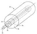
まず、図2を参照すると、本発明の方法により製造された光導波路ファイバ30が示されている。この光導波路ファイバは、中心軸33を備えた中心コア領域32と、外側ガラスコア領域34と、これらと同軸のクラッド領域36とを含む。光導波路ファイバ30は、円筒状ガラスプリフォーム70(図3)から形成され、このガラスプリフォーム70は、中心軸45を画成して内部を貫通して長手方向に延びる中心孔60を備えた中心コア領域42を有する。プリフォーム70はまた、双方とも中心コア領域42と同軸の、外側コア領域46とクラッド領域48とを含んでいる。例えば中心コア領域32,42は、ゲルマニウムをドープされた中心領域からなり、領域34,46は、種々の量の弗素および/またはゲルマニアドーパントを含む、複合屈折率輪郭(例えば secor輪郭)を備えた付加領域からなる。勿論、本発明はこれらドーパントを用いることにに限定されるものでも、複合屈折率輪郭を備えたファイバに限定されるものでもない。また、これに代わり、領域34を省略した、単純なステップ型屈折率を備えたファイバであってもよい。また、領域34は、典型的には純粋シリカからなる近似クラッド領域を含んでいてもよい。
【0035】
本発明の一つの実施の形態によれば、円筒状ガラスプリフォーム70は、酸化媒体内でシリカを主成分とする反応生成物を形成する少なくとも一つのガラス形成用先駆化合物を含む流体混合液の少なくといくつかの成分の化学反応によって形成されることが好ましい。この反応生成物の少なくとも一部は基体に導かれて多孔性体を形成し、その少なくとも一部は酸素に結合された水素を含む。
【0036】
上記多孔性体は、例えば、外付け気相堆積法(OVD法)を用いてスート層をベイトロッドに堆積させることによって形成される。このようなOVD法が図4に示されている。図4において、マンドレル50は筒状の一体ハンドルに挿入され、旋盤(図示せず)上に取り付けられる。この旋盤は、マンドレル50をスート発生バーナ54に近接させて回転と軸方向移動とをさせるように構成されている。マンドレル50が回転・移動させられるにつれて、一般にスートとして知られている、シリカを主成分とする反応生成物56がマンドレル50に向かって導かれる。シリカを主成分とする反応生成物56の少なくとも一部は、マンドレル50および一体ハンドル52の部分上に堆積されて、近端59と遠端61とを有する円筒状の多孔性スート体すなわちスートコアブランク58を形成する。本発明の実施の形態では、旋盤によって移動させると記載されているが、マンドレル50を移動させる代わりにスート生成用バーナ54を移動させてもよいことは当業者であれば理解されるであろう。さらに、本発明のこの態様では、スート堆積をOVD法に限定することを意図するものではない。それに限定されるもではないが、ガラス形成用先駆化合物の少なくとも一つが液相または気相で酸化媒体内に運ばれるというような、流動する流体混合物の成分の少なくともいくつかを化学反応させる別の方法によっても、本発明のシリカを主成分とする反応生成物の形成に用いることができる。さらに、内側気相法(IV法)および内付け化学気相堆積法(MCVD法)も本発明に適用可能である。本発明は、ロッド・イン・スート光導波路プリフォーム製造法とともに用いることを意図しないことが最も望ましいが、むしろ中心孔を閉じるために用いることがより好ましい。
【0037】
所望とする量のスートがマンドレル50上に堆積されると、スート堆積が終了してスートコアブランク58からマンドレル50が取り除かれる。マンドレル50が取り除かれると、スートコアブランク58には、軸方向に延びる中心孔60が画成される(図5)。スートコアブランク58は、一体ハンドル52に係合された吊下げハンドル62によって固結 (consolidation)炉64A内に垂直に吊り下げられる。固結炉64Aはスートコアブランク58を同軸的に取り囲むことが好ましい。一体ハンドル52はシリカを主成分とするガラス材料で形成され、コアブランク58の近端59が周囲に形成されている第1端部63と、内部表面67を画成する第2端部65とを備えている。これに代わり、一体ハンドル52の第2端部65は、スート堆積工程および固結工程の後に炎を用いて形成してもよい。一体ハンドル52は略コップの形をしており、内部空洞69を画成している。内部表面67は粗い手ざわりを有しているのが好ましく、この意味については後述する。スートコアブランク58の遠端61近傍に位置する中心孔60は、コアブランク58が固結炉64A内に配置されるのに先立ってガラス製の底栓66が装着されるのが好ましい。ガラス栓66は、固結中にスートコアブランクのスートが固結されてガラスになるときに、このガラス栓66が中心孔の端を効果的に密封するように、比較的低融点の(例えばスートコアブランクの融点よりも低い)ガラスで形成されるのが好ましい。底栓66の挿入は、多孔性スートコアブランク58の遠端61を閉じる好ましい方法であるが、遠端61を閉じて空気の流通を阻止するのに十分な他の方法および装置、例えば、それらに限定はされないが、遠端61に炎を当てる、および/またはかしめるという方法を用いてもよい。
【0038】
コアブランク58の近端59における中心孔60は、周囲の大気に開放されていても、あるいは固結工程に先立って、底栓66と類似の頂栓73を挿入することによって閉鎖されていてもよい。一つの実施の形態においては、このような中心孔を栓で塞ぐことを容易にするために、一体ハンドル52内の孔はスートプリフォーム58内の孔よりも大径にされており、かつ栓73のサイズは、栓73を一体ハンドル52の部分に挿入できるが、スートプリフォーム58の中心孔には嵌合するように、上記二つの孔の内径の中間値が選択される。これに代わる別の実施の形態では、頂栓73が、スートプリフォーム58の中心孔60を塞ぐのに供せられる下端のより細い部分(スートプリフォーム58内の中心孔を塞ぐのに十分な太さを有する)と、スートプリフォーム58の中心孔60に栓73が落ち込むのを防止するための上端のより太い部分(一体ハンドル52内の中心孔よりも太い)と、これら二つの太い部分を連結する中間部分とからなる。
【0039】
スートコアブランク58は、例えばこのスートコアブランク58を固結炉64A内で塩素を含む高温の雰囲気にさらすことによって化学的に乾燥させるのが好ましい。塩素を含む雰囲気は、このブランク58から作成された光導波路ファイバの特性に望ましくない影響を与える虞れのある水分および他の不純物をスートコアブランク58から効果的に取り除く。OVD法で作成されたスートコアブランク58においては、塩素がスート間を十分に通り抜けて、中心孔60の周囲領域を含むブランク58全体を効果的に乾燥させる。化学的乾燥工程に続いて、炉の温度は、スートを焼結されたガラスコアブランク55に固結させるのに十分な温度に上昇せしめられる。
【0040】
次にガラスコアブランク55は、必要に応じてコアケイン57のような中間ガラス物体を形成するのに用いられる。ここで用いられる中間ガラス物体とは、光導波路ファイバの製造に用いることができるガラス物体を意味し、光ファイバプリフォーム、コアケイン、ロッドとチューブの組合わせ体等を含む。しかしながら、上記孔は中心孔であり、したがって、本質的にロッド・イン・チューブ法によるものではない。ここで用いられるコアケイン(core cane)とは、当業者が従来から用いている用語で、光ファイバプリフォームのためのコア領域を少なくとも含む固結されたガラスロッドまたはチューブであって、これに付加的コアおよび/またはクラッド材料が付加されて完全な光ファイバプリフォームを形成する。ガラスコアブランクをコアケイン57(図6)に延伸するために、延伸炉64Bの温度は、固結されたガラスコアプリフォームブランク55の径を縮小してコアケイン57を作成するのに十分な温度に上昇せしめられる。固結されたコアブランク55が、これよりも細いコアケイン57に延伸される延伸工程中、中心孔60もまたコアケイン57の外径とともに細くなる(この孔の細くなることは図示されていない)。しかしながら、通常、中心孔60の初期の内径に対するコアブランク55の初期の外径の縮径は、真空の補助なしで中心孔60を塞ぐほど十分ではないので、中心孔60が完全に塞がらないことが好ましい。ガラスが化学的に乾燥されかつ固結された後は、独立したコアケインに延伸される間、中心孔60に水分が実質的に触れる機会がないように、中心孔60の両端は塞がれたままにしておくのが好ましい。
【0041】
コアケインの延伸工程中、延伸されるコアケイン57の周囲に間隔をおいて対称的に配置された複数のトーチ53によってコアブランク55から切り離される際に、コアケイン57の両端51,51′(図7)が密封される。このような密封工程は、各コアケイン57が切り離される際に、コアケイン57の半分溶融された両端が例えば炎で閉じられ(図示)、あるいはかしめて閉じられることによって達成することができる。コアケイン57の両端を、中心孔60が周囲の大気にさらされないように密封すると、水分および遷移金属のような不純物が中心孔内に閉じ込められることを著しく低減させる。光ファイバに線引きされる最終的なガラスコアブランク55(図8)が形成されると、コアケイン57の一体ハンドル52に最も近い位置にある端部から曲りタブ68(図9)が引き出される。これは、炎を当てる操作とコアケイン57端部の曲げ操作とによって行なうことができる。曲りタブ68は、ガラスプリフォーム70の中心から半径方向外方へ延びている。次に、図8に示されているような一体ハンドル52が、炎操作または孔60を大気にさらさせない他の適当な方法によって、各コアケイン57の端に取り付けられる。
【0042】
好ましい実施の形態では、次にコアケイン57がクラッディングステーションに移動され、そこで、追加のコア材料および/またはクラッド材料がコアケイン57上に施される。このオーバークラッディング工程は、クラッディングスートがマンドレル50上に堆積される代わりにコアケイン57上に施されることを除いては、コアスートブランク58(図4)を形成するのに用いられた最初のスート堆積方法と同一である。このオーバークラッディング工程は、クラッディング材料を例えばスート堆積によりコアケイン57上に堆積させることによって、あるいはこれに代わり、コアケインをクラッディンスリーブに挿入することによって達成される。もし追加のコアスート領域を形成すべきときには、得られたガラスコアブランク55(図8)を炉64内に配置し、そこから新たなコアケイン57Aを延伸し、次いでさらに追加のスート材料を施す工程が数回反復される。ガラスコアケイン上にスートクラッディングが施されると、スートクラッディングは化学的に乾燥され、次いでコアケイン57上でガラスに固結されて。完全なガラスファイバプリフォーム70を形成する(図9)。
【0043】
過去においては、および本明細書の冒頭に記載したように、多数のスート層の乾燥と固結の後に、ガラスプリフォーム70は、コアブランク形成後でかつそれからの光ファイバの形成に先立ついくつかの工程の一つにおいて、周囲の大気のような水分を含む環境に定常的にさらされていた。現在では、水(H2O)のような、またそれに限定されるものではないが、水素化合物を含む大気にガラスがさらされると、中心孔60を取り巻くガラス内に物理的に吸着された水分および化学的に吸着された水分が発生することが認識されている。さらに、大気にさらされる時間が長い程、ガラスに吸収される水の量が増大する。したがって、周囲環境、または水素化合物を含む環境への露出がいかに短時間であっても、中心孔を取り巻くガラスプリフォーム部分が再び湿気をおびる可能性がある。このような再吸湿は、OVD法によって形成されたブランクから標準的なファイバ製造工程を用いて製造される光導波路ファイバが示すウォーターピークの原因となる不純物をもたらす。
【0044】
ガラスプリフォーム70の中心孔60を大気に露出させる別の不利益は、中心孔60が、他の汚染物および遷移金属のような不純物にさらされる可能性があることである。得られた光ファイバ内に遷移金属が含まれると、減衰損失を招く。図7に見られるように、中心孔60の各端部を完全に密封することにより、中心孔60が有害な不純物にさらされることが軽減されまたは無くなる。例えば、その明細書がここに引例として組み入れられる1999年4月26付けで出願された米国仮特許出願 第60/131,003号には、水分による汚染を回避する方法が記載されている。
【0045】
図15に示されているように、本発明の方法のいくつかの変形が下記に記載されている。ここには、開示されている方法のいくつかの変形はすでに説明されているが、特定の実施の形態は限定を意図するものではなく、単に可能な順次の工程を例示したに過ぎない。
【0046】
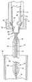
クラッドで覆われたコアケイン57(図9)を含む焼成されたガラスプリフォーム70が一旦形成されると、このプリフォームは、ガラスプリフォーム70を光導波路ファイバに線引きするための、垂直方向を向いているのが好ましい線引き炉に移される(図15のステップ100)。このガラスプリフォーム70は、下降ハンドル72に取り付けられた一体ハンドル52によって吊される(ステップ102)。中間ガラス物体(この中間ガラス物体が、コアケインであろうが、この場合のように光ファイバプリフォームであろうが関係なく)の孔を閉塞するためにここに用いられている炉は、中間ガラス物体の周囲に対称的に配置された熱源を備えていることが好ましい。例えば好ましい実施の形態においては、熱源が、温度勾配を有する発熱領域を備えた垂直方向を向いた円筒形の炉である。このような炉では、頂部から底部に向かって温度が上昇する発熱領域を採用している。したがって、中間ガラス物体が炉の頂部から挿入されて下降せしめられると、孔は底部から閉じる。塞がれるべき中心孔の内径に対する中間ガラス物体の外径の比率が非常に大きいので、外径の十分な減縮によって、孔が一様に閉塞されない原因となる負圧を必要とすることなく孔は閉じる。下降ハンドル72が線引き炉(図示せず)内に下降可能に配置され、ガラスプリフォーム70が内壁81を画成する線引き炉74内に図9に示すように下降せしめられる。ガラスプリフォーム70は、線引き炉74の内壁81によって周囲を取り囲まれていることが好ましい。半径方向内方に延びる破断用タブ80を備えた円筒状の内側ハンドル76(図9および図10)は、この内側ハンドル76の下端のボウル状の粗い手触りの嵌合面78が、一体ハンドル52の嵌合面67と嵌合して気密性シールを形成する態様で、一体ハンドル52内で嵌合される(ステップ104)。内側ハンドル76は内部空洞を有し、ハンドル76の下端には破断用タブ80が設けられている。この破断用タブ80は、後述するように、一体ハンドル52と内側ハンドル76との相対的回転により内側ハンドル76の破断用タブ80がガラスプリフォーム70の曲りタブ68に係合するように半径方向内方に延びている。
【0047】
一つの実施の形態においては、ガラスプリフォーム70が線引き炉74の高温ゾーン内に十分な時間降下せしめられて、ガラスプリフォーム70の中心孔60内のガス圧力を上昇させる(ステップ106)。次にガラスプリフォーム70は、高温ゾーン74から移動せしめられる(ステップ108)。内側ハンドル76の内部空洞71および一体ハンドル52の内部空洞69が減圧され(ステップ110)これにより、その他の微粒子物質のみでなくH2O のような汚染物質が除去される。次に、内側ハンドル76の内部空洞71および一体ハンドル52の内部空洞69にガス供給源84(図9)からの乾燥した不活性ガスまたは乾燥させるガス(例えば塩素)を再充填する(ステップ112)。供給される乾燥したまたは乾燥させるガスは、もしガスがガラスプリフォーム70の中心孔60内に入ったとしても、得られる光導波路ファイバ内に減衰損失を与えない清浄な乾燥したガスであることが好ましい。
【0048】
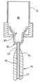
次に、ガラスプリフォーム70の曲りタブ68を折ることによって(ステップ114)、ガラスプリフォーム70の中心孔60が開放される。あるいは、曲りタブ68と内側ハンドル52とが連結されている部位よりも曲りタブ68の先端寄りの位置で曲りタブ68を罫がいてから、曲りタブ68を破断するようにしてもよい。曲りタブ68を破断するために、図11,図12に示されているように、内側ハンドル76が一体ハンドル52に対して相対的に回転せしめられ、その結果、内側ハンドル76が備えている破断用タブ80がガラスプリフォーム70の曲りタブ68に当接してタブ68を破断する。ガラスプリフォーム70の曲りタブ68が破断されると(図13)、ガラスプリフォーム70の中心孔60が一体ハンドル52の内部空洞69内に充填されているガスにさらされ、これにより、ガラスプリフォーム70から光導波路ファイバを線引きするのに先立って生じる可能性のある中心孔60の汚染が軽減または排除される。内側ハンドル76が一体ハンドル52に対して回転せしめられるのが好ましいが、一体ハンドル52を内側ハンドル76に対し回転させることもできる。さらに、内側ハンドル76と一体ハンドル52の双方を互いに他方に対して回転するようにしてもよい。
【0049】
曲りタブ68がガラスプリフォーム70から破断された後(図9,図13)、乾燥したまたは乾燥させるガスが内部ハンドルを継続的に通過し(ステップ116)、これにより、内側ハンドル76の内部空洞71、一体ハンドル52の内部空洞69、およびガラスプリフォーム70の中心孔60の汚染が排除され、再汚染の心配もなくなる。ガス供給源84からのガスの流量を調節し、かつガスを内側ハンドル76の内部空洞71に直接導くか、あるいは排気管86に導くかを制御するためにバルブ82が設けられている。排気管86には一方向弁88が接続され、排気管86への大気の侵入と、大気およびそれに伴う汚染物質によるガラスプリフォーム70の中心孔60の汚染を防止している(ステップ118)。一方向弁88は、バブラまたはチェックバルブの形式で、あるいは、大気が排気管86に逆流するのを防止するための種々の一方向弁の形式で提供することができる。あるいは排気管86は、排気管86へ逆流した大気が、ガラスプリフォーム70の中心孔60に達するのを阻止し得る長さを有するものであってもよい。
【0050】
ガラスプリフォーム70の中心孔60(図13)が開放されかつ不純物が取り除かれた後、ガラスプリフォーム70は炉74の高温ゾーンにさらに下降せしめられ、および/または、ガラスプリフォーム70からの光導波路ファイバ79の線引きを可能にするのに十分な温度に昇温される(ステップ130)。
【0051】
ファイバ線引きステップ130において、ガラスプリフォーム70は光ファイバ30(図2)に線引きされ、ガラスプリフォーム70の中心孔60はファイバ線引きステップ130中に閉塞される。ガラスプリフォーム70が光ファイバ30に線引きされるにつれて、ガラスプリフォーム70の外径が徐々に減縮される。閉塞されるべき孔の内径に比較して、プリフォームの外径が十分に大きいために、ガラスプリフォーム70の外径の縮小によって生じるガラスプリフォームの内部へ向かう力が中心孔60を首尾よく閉塞させる原因となる。ファイバ線引き工程中の表面張力および毛細管圧を含む孔閉塞力は、通常の光ファイバ製造法においてあるいはMCVD法またはIVプラズマ法においてチューブをつぶすのに典型的に用いられる真空による圧力とは異なる。外付け気相堆積法(OVD法)で完全に製造される典型的なガラスプリフォーム70においては、太さが7〜15cmと太く、中心軸孔60の内径は1〜10mmである。したがって、例えば7〜15cmの太さの範囲を有するファイバプリフォームの外径を、通常の光導波路ファイバの外径(例えば125μm)に減縮すると、外径の減縮に含まれる表面張力および毛細管圧力による適当な力が発生し、その結果、線引き中に特別に真空で引かなくとも、中心孔60が完全に閉塞される。特に、ファイバ線引きステップ130中に、例えば1Torrを超える浅い真空、寄り好ましくは8Torrを超える、さらに好ましくは100Torrを超える、さらに好ましくは500Torrを超える負圧を孔閉鎖/縮径ステップ中に加えることによって、孔を完全に閉塞させることができる。最も好ましいのは、中心孔60に加えられる圧力が大気圧(すなわち約750〜760Torr)に等しいかまたは、中心孔60に充填されているガスまたは乾燥させるガスの排出圧力に起因する僅かに正圧(すなわち,大気圧が760Torrと推定される場合に約764.6Torr)である。線引き作業中に約761.8〜769Torrの正圧を維持することが好ましい。この方法により、ファイバ線引きステップ130中に中心孔60を、中心線33(図2)の周りにおける光ファイバ30の円形対称性を実現するのに十分な圧力状態に維持することができる。ここに開示された圧力は絶対圧力である。
【0052】
図16には、中心点22が対称的な形状のガラス層24によって囲まれた光ファイバの中心部の断面が符号20で示されている。対称的な中心輪郭は、単一モードファイバにおける偏光モード分散を低減し、多モードファイバにおいては、中心領域における輪郭を所望の屈折率輪郭に一致させることを可能にすることによって、広い帯域幅が得られる適当な屈折率輪郭を構築する能力を著しく向上させる。
【0053】
好ましい他の実施の形態においては、図15のステップ120に示されているように、内側ハンドル76および一体ハンドル52を浅い真空に引くのに先立って、曲りタブ68が破断される。ステップ120において曲りタブ68が破断された後に、内側ハンドル76(図9)、および一体ハンドル52の内部空洞69、したがってガラスプリフォーム70の中心孔60が浅い真空に引かれ、これによって、内側ハンドル76の内部空洞71および一体ハンドル52の内部空洞69内から、同様にガラスプリフォーム70の中心孔60内から、上述した汚染物質が除去される(ステップ122)。この工程中に印加される真空は、ガラスプリフォーム70の中心孔60をつぶすのに通常必要とするものよりずっと浅く、その値は上述の通りである。次に、内側ハンドル76の内部空洞71、一体ハンドル52の内部空洞69、およびガラスプリフォーム70の中心孔60には、乾燥した、または乾燥させるガスが満たされる(ステップ124)。また、ガラスプリフォーム70の中心孔60は、ガラスプリフォーム70の中心孔60に負圧を印加することなしに乾燥した、または乾燥させるガスにさらされる(ステップ126)。もしガラスプリフォーム70の中心孔60に、ステップ122に示されているように減圧され、かつステップ126に示されているように、乾燥した、または乾燥させるガスにのみさらされるとしても、ガラスプリフォーム70の中心孔60は大気にさらされないことが好ましいことに注目されたい。
【0054】
内部ハンドル76と一体ハンドル52との間の連結を解除することにより、一体ハンドル52の内部空洞69(図14)が大気にさらされると、得られた光導波路ファイバの水素によって生じる減衰が増大するようである。したがって、一体ハンドル52を取り巻く空間90は、内側ハンドル76が一体ハンドル52と非係合状態になった後も、ガス供給源84(図9)からの乾燥した、または乾燥させるガスにより継続的に清浄化されていることが好ましい。
【0055】
この光導波路ファイバの作成方法は、ステップ110の内側ハンドル76の内部空洞71の減圧、および/または、ステップ120の曲りタブ68のガラスプリフォーム70からの破断に先立って、ガラスプリフォーム70が炉の高温ゾーン74に降下せしめられないことを除いては、上述の好ましい実施の形態のために記載されたのと同様の態様で完了される。
【0056】
ガラスプリフォーム70が高温ゾーン74内で加熱される間、溶融ガラス玉91がガラスプリフォーム70の遠端77に集まり始める。ガラスプリフォームが高温ゾーン内で加熱されている間、ステップ112またはステップ124で、中心孔60が定常的にガスで清浄化されているならば、乾燥した、または乾燥させるガスの圧力を低下または排除して、ガラス玉91の肥大化を防止する必要がある。ガラス玉91が破裂点まで肥大化するのを許容すると、乾燥した、または乾燥させるガスがガラスプリフォーム70の遠端77および中心孔60の背後の閉塞部から抜けて、密実な中心コア32を備えた光導波路ファイバ30(図2)の形成を許容することになる。さらに、ガラス玉91の破裂を許容すると、大気が中心孔60に入って中心孔60を、したがって得られた光導波路ファイバの汚染を許容することになるかも知れない。したがって、ガラスプリフォーム70から光導波路ファイバを線引きしている間における中心孔60内の乾燥した、または乾燥させるガスの圧力は、ガラス玉91が破裂せず、さらに、線引きステップ130中、中心孔60内に存在するガスが、一体ハンドル52を通じて逆流することによって脱出することが可能なように、十分低く保たれていることが好ましく、これにより得られたファイバ内にガスの詰まった空隙が生成されることなしに中心孔60が閉塞されるのを可能にする。
【0057】
図16を参照すると、本発明の方法を用いて製造された単一モードファイバのための光ファイバプリフォームの断面の中心輪郭が符号20で示されている。この図は、単一モード光ファイバ線引き作業後のプリフォームの根本部分の太さ約1cmの領域における断面図である。図16に示されているように、中心部20は中心点22の周りにほぼ対称的な円を描いている。中心点22近傍の中心点22を取り巻くガラス層24は極めて対称的かつ円形である。この断面は、実際の光ファイバではなくプリフォームの根本部分ではあったが、このプリフォームから線引きされた光ファイバにも同様の一様な対称性が存在する。さらに、多モードファイバコアケインおよびこれから線引きされた光ファイバにおいても同様の結果を得ることができる。中心点22近傍の層が対称性および同心性を有するように作成された単一モードコアケインは、0.02psec/sqrt-km未満の偏光モード分散値を得ることが可能である。図16においては図の中心から外れている中心点22は、光ファイバの全長に亘って延びる中心線上に留まっている。同様に、対称的な円形が光ファイバの全長に亘っている。
【0058】
ここに開示された方法を用いると、中心線から約0.1μmの距離において中心線を取り囲むガラス層が十分な対称性を保ちつつ、外径125μmの光ファイバが得られ、堆積されたガラス層の直径偏差、は0.025μm未満、すなわち、中心線から約0.08から0.15μmの間に位置するガラス層の最大直径から最小直径を減算した値が0.025μm未満であり、さらには約0.015μm未満であることが好ましい。本発明者は、ここに開示された方法を用いることにより、このようなファイバを得ることができた。本発明の方法で生産された図16に示すようなファイバの中心部輪郭を、従来の方法で生産された図1に示すようなファイバの中心部輪郭と比較すると、従来の方法で生産されたファイバの中心部輪郭は、このような層の一様な対称性および同心性は示していない。これと反対に、本発明の方法で生産されたファイバは、中心線の回りの同心的で対称的なガラス領域を示している。
【0059】
中心孔60を閉塞させる製造工程(図9)中のどの時点においても真空を用いず、かつファイバ線引き工程130(図15)で撚りを施す技法に頼らない本発明の方法により、低レベルの偏光モード分散が達成された。さらに詳細に述べれば、請求の範囲に記載された発明の製造方法は、0.2psec/sqrt-km未満の、より好ましくは0.1psec/sqrt-km未満の、最も好ましくは0.05psec/sqrt-km未満の偏光モード分散値を有する単一モード光ファイバの形成を可能にする。ここに記載された方法を用いると、線引き工程中に光ファイバに撚りを施すことなしに、0.02psec/sqrt-km未満の偏光モード分散値を有する単一モード光ファイバが得られた。PMDを低減するために、通常線引き作業中にファイバに撚りが施されが、そうすると構造中に撚りが生じたファイバが得られる。実際に、ここに開示された方法を用いると、PMD測定器の測定限界である0.007psec/sqrt-kmというような低いPMDを有する、全く撚りが施されていない単一モードファイバ(特に、Corning 社製のLEAF non-zero dispersion shifted 光ファイバ)が得られた。本発明により作成された単一モード光ファイバには、撚りを施すための回転を与えない方が好ましいが、ファイバの長さ1メートルについて3回未満の回転を与えて撚りを施した場合でも、上述のような低いPMD値を得ることができた。特に、同時に、乾燥した、または乾燥させるガスで中心孔60を清浄化して同時に水素を減らすことにより、1550nmにおいて0.19dB/kmの減衰損失を達成しながら、このような低レベルの偏光モード分散値が維持された。
【0060】
上述の単一モードファイバに関する製造方法と同様の工程を用いて、多モードファイバを製造することができる。しかしながら、多モードファイバにおいては減衰損失は重大ではないから、延伸およびクラッド堆積工程中に、必ずしも多モードコアスートの両端を閉塞する必要はない。しかしながら、中心孔は、上述した単一モードファイバの場合のように閉塞することが好ましい。多モードファイバについては、中心孔の対称的な閉塞により、ファイバ屈折率輪郭を有する中心領域が望ましい精密な輪郭形状に調整することを可能にする。このことは、得られたファイバがレーザー源によって示される小さいスポットサイズとともに使用される場合に、中心帯域幅を改善することができる。
【0061】
図17に示されているように、そして本発明によれば、本発明の方法により製造された光ファイバ132が光ファイバ通信システム134に用いられている。システム134は、受信機138と、送信機136と受信機138との間に光信号を伝送するための光導波路ファイバ132とを含む。システムの大多数において、ファイバ132の各端末は双方向通信が可能であり、送信機136および受信機138は単に説明のために示したに過ぎない。
【0062】
ここに開示された方法は、線引き時に中心孔を閉じることのみでなく、例えばコアケインを作成する延伸工程のような独立した縮径工程にも使用することができる。もし、中間的ガラス物体内に存在する孔の内径に対する中間的ガラス物体の外径の比が十分に大きい場合には、中間的ガラス物体の外径を減縮させることによって、中心孔を閉じるのに十分な力が生じる。したがって、もし中間的ガラス物体の外径が十分に大きい場合には、このガラス物体内の孔は、真空の力を借りることなしに、縮径作業中に閉じる。この方法により、同様の孔の対称的な閉塞が達成できる。
【0063】
ここに開示された発明は、主として中心孔を閉塞することに間するものであるが、この方法は中心孔の閉塞に限定されるものではなく、光ファイバの製造に用いるための光ファイバプリフォームまたはその他の中間的ガラス物体の長さ方向に沿って存在する空隙を実質的に閉塞するのにも用いることができる。これは、予め製造されたコアブランクすなわちコアケインにガラススリーブを組み付けることによって生じる空隙のみでなく、ロッド・イン・チューブ法の結果として形成された空隙をも含む。
【0064】
本発明の製造方法は、低減衰損失と低偏光モード分散とを示す光導波路ファイバとなるプリフォームの孔の再現可能な、対称的な、一様な閉塞を提供する。当業者であれば、さらなる利点および改良点が直ちに心に浮かぶであろう。それ故に、本発明は、ここに開示され、記載された細目および代表的な装置に限定されない幅広い態様を含んでいる。したがって、添付の請求の範囲に定義された本発明の精神および概念から離れることなしに、ここに開示された方法およびプリフォームについての種々の改良が可能であろう。
【0065】
具体例
下記の具体例の大部分は、本発明によって製造され、Corning 社から販売されているLEAF光ファイバとして知られているファイバに関するものである。シリカにほぼ等しい屈折率を有する周囲領域に取り囲まれ、ゲルマニアを再び多量にドープされた環状領域に取り囲まれ、次にSiO2 からなる近似クラッド領域が設けられた、ゲルマニアを多量にドープされた中心領域からなる、ゲルマニアをドープされたコアをAl2O3セラミック製マンドレル上にOVD法を用いてスートとして堆積させた。クラッド領域の半径に対するコア領域の比は0.4であった。次にマンドレルを取り除き、コアスートプリフォームに頂栓と底栓とを挿入した、次にこのコアガラスコアプリフォームを、先ずヘリウムキャリアガス中の1%の塩素に1000℃で2時間さらして清浄化し、次に1460℃で焼成することによって固結させた。この固結工程の結果、60mmの外径と、約6mmの内径を備えた中心線に沿う孔とを有する清浄化され、かつ乾燥されたガラスプリフォームが得られた。頂栓と底栓とは、この固結されたガラスプリフォームの頂部と底部を密封する結果となった。次に固結されたガラスプリフォームを1900℃の炉内に挿入して中空のコアケインに延伸し、プリフォームの外径を約10mmに減縮した。その結果、中心孔の内径は1mmになった。プリフォームからコアケインを延伸するにつれて、中空のコアケインの長さは1メートルになり、次に、火炎を用いて焼切りと端部密封とを行ない、これにより、コアケインの中心孔を密封し、中心孔に沿う領域を密封状態に保った。
【0066】
コアケインの一端にハンドルを取り付け、コアケイン上に追加のスートを堆積させて、光ファイバに線引きするのに適した光ファイバプリフォームを形成した。次にこの得られたスート体を清浄化し、かつ上述のように固結させて、ガラス光ファイバプリフォームの中心線に沿って延びる内径1mmの孔を備えた外径約56mmのガラス光ファイバプリフォームを得た。中心孔は依然としてその両端において密封されていた。次にこのガラス光ファイバプリフォームに一体ハンドル52を取り付け、線引き炉の頂部に挿入した。次に内側ハンドル76を下降させて、光ファイバプリフォームの一体ハンドル52に嵌着した。100%のヘリウムガスからなる清浄かつ乾燥した雰囲気を提供した後、コアケインの頂部を破断して開放し、光ファイバプリフォームを炉内に下降させて、そこからファイバを線引きした。たとえ中心孔内の圧力が大気圧に保たれていたとしても、プリフォームの頂部の破断によって、中心孔内からのガスの脱出が許容された。プリフォームの外径が約1ないし2mmまで減縮されている間に、内部の中心孔は極めて対称的に完全に閉塞された。かくして、光ファイバプリフォームにおける10%未満の縮径によって中心孔を閉塞することができた。得られて光ファイバは、1550nmにおいて1キロメートル当り約0.19dBの減衰損失を示し、かつ長さ1kmのファイバのサンプルのPMDを、ヒューレット・パッカード社製の測定ベンチで測定したところ、約0.02 psec/sqrtであった。このファイバは撚りが全く施されない状態で線引きされた。このことは、線引き作業中にファイバまたはプリフォームに対して撚りが施されなかったことを意味する。
【図面の簡単な説明】
【図1】コアケインの作成に用いられる延伸作業における真空引きによって形成された中空コア断面の中心輪郭の概略図
【図2】光導波路ファイバの部分的斜視図
【図3】ガラス光ファイバの部分的斜視図
【図4】スートコアブランクを作成するための外付け気相堆積法を示す概略図
【図5】固結炉内に配置されたスートコアブランクの縦断面図
【図6】ガラスコアケインに延伸されたスートコアブランクの縦断面図
【図7】ガラスコアブランクから切断されたコアケインの縦断面図
【図8】固結・線引き炉内に配置された、追加スートで覆われたコアケインの縦断面図
【図9】概略的に示された線引き機内に配置された、完全に固結されたガラス光ファイバプリフォームの縦断面図
【図10】図9に示されたガラス光ファイバプリフォームの拡大部分断面図
【図11】ガラスプリフォームの曲りタブに整列せしめられた破断用タブを備えた内側ハンドルが外側ハンドルの内部に配置された状態を示す、図10のXI−XI線に沿った断面図
【図12】内側ハンドルの破断用タブがガラスプリフォームの曲りタブに当接した状態を示す、図11と同一の平面に沿った断面図
【図13】ガラスプリフォームの曲りタブが破断された状態で線引き炉内に配置されたガラスプリフォームの拡大部分断面図
【図14】内側ハンドルが外側ハンドルから取り外された状態で線引き炉内に配置されたガラスプリフォームの拡大部分断面図
【図15】本発明の方法の各工程を示すフローチャート
【図16】本発明により作成された導波路ファイバの、実質的に対称的な円形輪郭を示す概略図
【図17】本発明の光ファイバを用いた光ファイバ通信システムの概略図
【符号の説明】
10,20 中心輪郭
12,22 中心点
14,24 ガラス層
30 光導波路ファイバ
32 中心コア領域
52 一体ハンドル
55 ガラスコアブランク
57 コアケイン
58 スートコアブランク
60 中心孔
68 曲りタブ
70 ガラスプリフォーム
72 外側ハンドル
76 内側ハンドル
80 破断用タブ[0001]
Cross-reference of related applications
This application claims priority to US Provisional Patent Application No. 60 / 131,012, filed Apr. 26, 1999, entitled “Optical Fiber with Substantially Circular Symmetric Core and Method of Manufacturing the Same”. It is an application to do.
[0002]
Background of the Invention
1.Field of Invention
The present invention relates generally to the field of optical waveguide fibers, and more particularly to a method of manufacturing an optical waveguide fiber with low polarization mode dispersion and low attenuation loss.
[0003]
2.Technical background
An important goal of the telecommunications industry is to transmit larger amounts of information over longer distances and in shorter times. In general, as the number of system users and system usage frequency increases, so too does the demand on system sources. One way to meet this requirement is to increase the bandwidth of the media used to transmit information. In an optical communication system, a demand for an optical fiber having a wide bandwidth is particularly high.
[0004]
In recent years, there have been significant advances in the manufacture of optical waveguide fibers that have enhanced the usable light transmission capabilities of the fiber. However, it is well known that when an electromagnetic wave is transmitted through an optical waveguide fiber, attenuation loss is caused by several mechanisms. Some of these mechanisms could not be reduced, while others were eliminated or at least substantially reduced.
[0005]
A particularly problematic aspect of the attenuation loss of the optical fiber is attenuation loss based on absorption of the optical waveguide fiber by impurities existing in the optical waveguide region of the fiber. Of particular impediment is the attenuation loss due to hydroxyl groups (OH), which are present when there is a hydrogen source in the fiber material or some source that is dispersed in the glass during the fiber manufacturing process. Can be formed when hydrogen is produced from
[0006]
Hydrogen is SiO in the glass structure.2And / or GeO2And / or OH and / or OH in combination with oxygen in the oxygen-containing compound2 Form a bond. The attenuation loss, which is usually maximum in the 1380 nm band due to OH or moisture in the glass, reaches a height of about 0.5 to 1.0 dB / km. The “1380 nm band” used herein is defined as a wavelength range from about 1330 nm to about 1470 nm. Maximum attenuation loss, commonly referred to as “water peak”, has been prevented by not using the 1380 nm band for electromagnetic wave transmission.
[0007]
To date, telecommunication systems have avoided water peaks that exist in the 1380 nm band by operating in the 1310 nm band and / or 1470 nm band. With the advent of wavelength division multiplex communication (WDM) capable of operating telecommunications systems over a wide wavelength range and advances in amplifier technology, all wavelengths between about 1300 nm and about 1650 nm are data in optical telecommunications. It was used for transmission. Removing the water peak from the optical waveguide fiber used in these systems is important in that the system operates over this entire wavelength band.
[0008]
In the manufacture of optical fibers, various methods can be used to deposit various soot layers. In the external vapor deposition (OVD) method, a soot core blank is formed by depositing precursor components including silica and germanium on a ceramic bait rod in the presence of oxygen. While rotating the bait rod, the precursor component is fed to the flame burner to form a soot, which is then deposited on the bait rod. When a sufficient amount of soot is deposited, the bait rod is removed and the resulting soot core blank is consolidated into a glass core blank. The soot core blank is usually consolidated by suspending the soot core blank in a consolidation furnace and heating at a temperature and for a time sufficient to allow the soot core blank to be consolidated into glass. Prior to the consolidation step, the soot core blank is preferably chemically dried, for example by exposing it to chlorine gas at an elevated temperature. As a result, a cylindrical glass core blank having holes along the center line is obtained.
[0009]
The glass core blank is then placed, for example, in a furnace, heated at a temperature of about 2000 ° C. and drawn into a thinner core cane. During the stretching process, the central hole is collapsed by properly evacuating the central hole of the core blank (eg, a pressure of less than 200 mTorr). Such reduced pressure ensures complete blockage of the glass core blank along the central hole. After this stretching step, the resulting core cane is usually covered with cladding soot, for example by deposition of cladding soot using the OVD method. When covered with a sufficient amount of clad soot, the soot-covered core cane is chemically dried and consolidated to form an optical fiber preform. Different methods (eg, MCVD and others) can be used to form the elements used to make the preform, but many of those methods (eg, MCVD) are occluded prior to drawing the fiber. Finish with a cylindrical tube or other intermediate glass object with holes. In these production methods, a vacuum is formed at a certain point in the production process to close holes existing between glass components without greatly changing the outer diameter.
[0010]
There are also drawbacks to closing central holes or other voids in glass core blanks or other optical fiber preforms by vacuum. Such reduced pressure produces an asymmetric profile at the center of the cane, for example as shown in FIG. In FIG. 1, the entire cross-section of the core cane including the center point 12 surrounded by the
[0011]
This asymmetric core shape is believed to be key to the polarization mode dispersion (PMD) that forms the dispersion that occurs when one component of light propagates faster than the other components orthogonal thereto. PMD limits the data transmission rate of telecommunications systems using fiber and can be very damaging depending on the degree of presence in single mode fiber. This is noticeable in single-mode fibers and multimode fibers, both having an outer diameter of about 125 μm. However, the single mode fiber has a small diameter core of about 8 μm, for example. This dimensional relationship makes single mode fibers very sensitive to polarization mode dispersion caused by asymmetric blockage of holes that occur during fiber manufacture. Thus, PMD reduction is an important goal in fiber manufacturing, especially in single mode fiber. In contrast to the small core size of single mode fiber, the core region of multimode fiber has a diameter of 62.5 μm or 50 μm. In a multimode fiber, the asymmetric blockage of the hole makes it impossible to adjust the refractive index profile of the innermost part near the fiber centerline. As a result, when a laser is used to transmit light over such a fiber, the laser is offset slightly from the centerline of the multimode fiber to avoid an asymmetric hole blockage region.
[0012]
One method used to reduce PMD is to twist the optical fiber during the fiber drawing operation, where the fiber follows its central axis when drawn from the molten root of the molten blank. And mechanically twisted. This twist allows the orthogonal components of the light to be coupled together and the dispersion is averaged to reduce PMD. However, twisting is a rather complex process to mitigate the effects of asymmetric blockage of holes, which slows the drawing speed, disturbs the coating dimensions, and reduces the strength of the optical fiber. become. Therefore, it is desirable to produce a fiber that exhibits low PMD without resorting to such twisting.
[0013]
In addition, the asymmetric core shape causes a variation in core diameter along the length of the fiber core so that the transmitted light is at different points along the length of the optical fiber at different core cross sections. It will appear in the area. Furthermore, the asymmetrical profile at the center can reduce the bandwidth of the laser incident on the multimode fiber.
[0014]
Another drawback of using a vacuum to close the center hole is that such a process creates a gap along the centerline that further impairs the transmission characteristics of the optical fiber.
[0015]
Although the manufacture of optical waveguide fibers is usually accompanied by chemical drying and consolidation processes, such optical waveguide fibers have been found to exhibit a relatively high level of attenuation loss measured at about 1380 nm. ing. This shortcoming has been overlooked because currently used telecommunications systems do not operate at or near 1380 nm. However, recent advances in WDM, amplifier technology and laser sources have made it a priority to eliminate water peaks measured at 1380 nm. The water peak is greatly affected by moisture trapped in the glass during the fiber manufacturing process. In the case of the OVD method, it is believed that most of the moisture is trapped in the central region of the core prior to or during the blockage of the central hole. Although the blank is chemically dried and fired during consolidation, it has been found that the glass region surrounding the central hole and defining the central hole re-absorbs moisture after drying. Usually, such reabsorption is due to water (H2O 2) caused by physical moisture absorption, chemical moisture absorption or moisture diffusion by exposing the central hole to an atmosphere containing hydrogen compounds such as, but not limited to.
[0016]
Summary of the Invention
The present invention relates to a method of making an optical fiber, and provides an intermediate glass object with a central hole therein for use in manufacturing an optical fiber to reduce the outer diameter of the glass object. Each step of reducing the outer diameter of the glass object while controlling the pressure inside the central hole so that it is heated to a sufficient temperature and sufficient to uniformly and symmetrically close the central hole. .
[0017]
One embodiment of the present invention provides an intermediate glass object having holes or annular voids plugged at least one end to prevent gas flow for use in optical fiber manufacture, and then In this optical fiber manufacturing method, the glass object is heated to a temperature sufficient to reduce its outer diameter. The method further includes applying a pressure in excess of 500 Torr to the hole to reduce the outer diameter of the glass object to create a uniform and symmetrical blockage at the center.
[0018]
The step of closing the holes is preferably performed under conditions sufficient to uniformly and symmetrically heat the intermediate glass object prior to and / or during the closing step. Such symmetrical heating can be achieved, for example, by using a cylindrical furnace when the intermediate glass object is a cylindrical fiber optic preform or other cylindrical intermediate glass object.
[0019]
Another embodiment of the present invention is an optical fiber including a fiber core with a plurality of glass layers and a centerline. The optical fiber further includes a fiber cladding surrounding the fiber core, and the plurality of glass layers surrounding the centerline are sufficiently symmetrical and circular, resulting in a polarization mode dispersion value of less than 0.2 psec / sqrt-km. Have.
[0020]
Yet another embodiment of the present invention is an optical fiber communication system including a transmitter, a receiver, and an optical fiber for transmitting an optical signal between the transmitter and the receiver. The optical fiber includes a fiber core having a plurality of glass layers and a centerline, and a fiber cladding surrounding the fiber core, the plurality of glass layers surrounding the centerline being sufficiently symmetrical and circular, resulting in: It has a polarization mode dispersion value of less than 0.2 psec / sqrt-km.
[0021]
Yet another embodiment of the present invention is an optical fiber communication system including a transmitter, a receiver, and an optical fiber for transmitting an optical signal between the transmitter and the receiver. The optical fiber includes a fiber core having a plurality of glass layers and a centerline, and a fiber cladding surrounding the fiber core, the plurality of glass layers surrounding the centerline being sufficiently symmetrical and circular, resulting in: It has a polarization mode dispersion value of less than 0.2 psec / sqrt-km. The optical fiber is also twisted less than 3 times over a 1 meter length of fiber.
[0022]
Still another embodiment of the present invention provides a cylindrical glass fiber preform having a longitudinally extending central hole and includes light plugs that plug ends of the central hole to prevent gas flow. The present invention relates to a method for manufacturing a waveguide fiber. The method further includes attaching an outer handle with a mating end to one end of the preform, and providing an inner handle having a mating end and a fluid receiving end and coupled to a gas supply source. Coupling the end and the mating end of the inner handle. The method further includes exposing the preform's center hole to a gas, heating the preform to a temperature sufficient to soften it, and drawing the preform into an optical waveguide fiber. Including closing the central hole.
[0023]
In yet another embodiment, an optical waveguide fiber manufacturing method according to the present invention comprises a cylindrical glass optical fiber plug having a longitudinally extending central hole that is plugged at both ends to prevent gas flow. Including a reform, a bent tab is formed at one end of the preform. The method further includes attaching an outer handle with a mating end to one end of the preform, an inner end communicating with the gas supply with the mating end, a radially extending break tab, and a fluid receiving end. Providing a handle and coupling the mating end of the outer handle to the mating end of the inner handle. This method further heats the preform sufficiently to increase the gas pressure in the center hole of the preform so that the outer handle and the inner handle are connected to each other, and the inner handle break tab becomes the bent tab of the preform. Relatively rotate until contact, thereby breaking the bent tab, heating the preform to a temperature at which the preform is sufficiently softened, and drawing the preform into an optical waveguide fiber. Including closing the central hole.
[0024]
Yet another embodiment of the present invention provides a cylindrical shape with an axially extending hole plugged at both ends to prevent gas flow and a breakable tab provided at one end of the hole. An apparatus for opening an axial hole in an optical fiber preform. The preform includes an outer handle attached to one end of the preform and having a mating end, a mating end, a radially extending break tab, and a fluid receiving end that communicate with a gas supply. And the mating end of the inner handle is coupled to the mating end of the outer handle so that the outer handle and the inner handle are relative to each other until the breaking tab of the inner handle abuts the bending tab of the preform. Rotation and thereby breaking the bent tab exposes the axial bore of the preform.
[0025]
Yet another embodiment of the present invention is a preform for manufacturing an optical fiber, the preform comprising a cylindrical glass object with an axial bore extending in a longitudinal direction, and the glass object. A plug provided at one end of the glass object to seal one end and seal one end of the axial hole, and a curved glass tab to seal the other end of the axial hole, the tab being radially And a longitudinally extending tip that can be broken to expose the axial hole.
[0026]
The manufacture of optical fibers and other waveguides according to the present invention provides numerous advantages over the prior art with respect to reducing polarization mode dispersion. Because the central hole in the intermediate glass object of the present invention is plugged under conditions that produce a uniform and symmetrical hole blockage, the fiber drawn from such an intermediate glass object is a conventional fiber. Compared to the above, extremely low polarization mode dispersion is exhibited. In the method of the present invention, the intermediate glass object is a fiber optic preform, the preform comprising a hole that is closed during drawing, and the predetermined positive or negative pressure applied during drawing is substantially equal to Forming a fiber with a circular center profile, i.e., with a substantially circular symmetric core, the adjacent glass layers draw a precisely symmetric circle as they move away from the centerline. Similar effects can be obtained for intermediate glass objects that are not entirely perfect optical fiber preforms. For example. The intermediate glass object is a core cane foam having a central hole therein, and the center hole is closed during the stretching operation, and the outer diameter of the core cane foam is sufficiently reduced in the stretching operation. The holes are closed to form the core cane. In this core cane formation and hole closing process, sufficient positive or negative pressure is applied during stretching to cause symmetrical hole closing. The holes in the intermediate glass body are preferably closed without using a rod-in-tube manufacturing method. As a result of using the method of the present invention, single mode fibers exhibiting low polarization mode dispersion could be made without resorting to twisting or other PMD mitigation methods.
[0027]
The method of the present invention can also be used to form multimode optical fibers that are inherently suitable for use with laser light sources. In the laser beam emission method, the laser spot size can be made smaller than the entire core size. If the laser is directed to asymmetric glass regions, these asymmetric glass regions obstruct the path through which the laser beam must otherwise pass. It is therefore desirable to have a uniform and symmetrical concentric glass layer around the core of the fiber. Such concentric layers can be obtained by using the method of the present invention.
[0028]
The various embodiments disclosed herein provide many additional advantages over other previously known methods. For example, the amount of impurities such as moisture and transition metals that are trapped in the central region of the core blank before the core blank is drawn into the optical fiber can be significantly reduced. Thus, optical waveguide fibers made from such core blanks exhibit lower water peaks at 1380 nm and throughout the 1380 nm band and are therefore manufactured by standard methods from preforms manufactured by the OVD method. Lower optical attenuation in the 1380 nm band than the optical waveguide fiber made. Furthermore, optical waveguide fibers made from such core blanks exhibit low attenuation loss.
[0029]
A further advantage of the method of the present invention is that an optical waveguide fiber manufactured in this way can operate at any wavelength within the wavelength range between about 1300 nm and 1680 nm without significant light attenuation. That is. Furthermore, the method of the present invention can also be implemented without economically constructing the device and producing waste that is harmful to the environment.
[0030]
A further advantage of the manufacturing method of the present invention is that the optical fiber produced by this method has fewer voids along its centerline. By not pulling a vacuum when the hole diameter is reduced or when the hole is closed, the air gap in the fiber is remarkably reduced, thereby reducing the light reflection associated with the air gap.
[0031]
These and other advantages of the present invention will be further understood and appreciated by those skilled in the art by reference to the following description of the specification, claims and appended drawings.
[0032]
The foregoing general description and the following detailed description are merely illustrative of the invention and provide an overview or framework for understanding the nature and characteristics of the claimed invention. It is intended. The accompanying drawings are provided for a further understanding of the invention and are incorporated in and constitute a part of the specification. The drawings contribute to the description of various embodiments of the present invention, the description, and the description of the main configuration and operation of the present invention.
[0033]
Preferred embodiment
Reference will now be made in detail to the preferred embodiments of the present invention as illustrated in the accompanying drawings. Throughout the drawings, similar parts are denoted by the same reference numerals as much as possible.
[0034]
First, referring to FIG. 2, an
[0035]
According to one embodiment of the present invention, the
[0036]
The porous body is formed, for example, by depositing a soot layer on a bait rod using an external vapor deposition method (OVD method). Such an OVD method is shown in FIG. In FIG. 4, a
[0037]
Once the desired amount of soot has been deposited on
[0038]
The
[0039]
The
[0040]
The
[0041]
During the core cane stretching process, when the
[0042]
In a preferred embodiment, the
[0043]
In the past, and as described at the beginning of this specification, after drying and consolidating multiple soot layers, the
[0044]
Another disadvantage of exposing the
[0045]
As shown in FIG. 15, several variations of the method of the present invention are described below. Although several variations of the disclosed method have already been described herein, the specific embodiments are not intended to be limiting and merely illustrate possible sequential steps.
[0046]
Once the fired
[0047]
In one embodiment, the
[0048]
Next, the
[0049]
After the
[0050]
After the central hole 60 (FIG. 13) of the
[0051]
In the
[0052]
In FIG. 16, a cross section of the center portion of the optical fiber in which the center point 22 is surrounded by a
[0053]
In another preferred embodiment, the
[0054]
By releasing the connection between the
[0055]
This method of making an optical waveguide fiber is such that the
[0056]
While the
[0057]
Referring to FIG. 16, the central profile of a cross section of an optical fiber preform for a single mode fiber manufactured using the method of the present invention is indicated at 20. This figure is a cross-sectional view in a region having a thickness of about 1 cm at the base portion of the preform after the single-mode optical fiber drawing operation. As shown in FIG. 16, the
[0058]
Using the method disclosed herein, an optical fiber having an outer diameter of 125 μm is obtained and a deposited glass layer, while the glass layer surrounding the center line remains sufficiently symmetrical at a distance of about 0.1 μm from the center line. The diameter deviation of the glass layer is less than 0.025 μm, ie, the maximum diameter of the glass layer located between about 0.08 and 0.15 μm from the center line is less than 0.025 μm, and Preferably it is less than about 0.015 μm. The inventor was able to obtain such a fiber by using the method disclosed herein. Compared with the fiber center profile as shown in FIG. 1 produced by the conventional method, the fiber profile as shown in FIG. 16 produced by the method of the present invention was produced by the conventional method. The center profile of the fiber does not show the uniform symmetry and concentricity of such layers. In contrast, the fiber produced by the method of the present invention exhibits concentric and symmetric glass regions around the centerline.
[0059]
The method of the present invention does not use vacuum at any point during the manufacturing process (FIG. 9) to close the
[0060]
A multimode fiber can be manufactured using a process similar to the manufacturing method for the single mode fiber described above. However, attenuation losses are not critical in multimode fibers, and it is not necessary to plug both ends of the multimode core soot during the draw and clad deposition process. However, it is preferred that the center hole be occluded as in the single mode fiber described above. For multimode fibers, the symmetric occlusion of the center hole allows the center region with the fiber refractive index profile to be adjusted to the desired precise profile. This can improve the center bandwidth when the resulting fiber is used with a small spot size indicated by the laser source.
[0061]
As shown in FIG. 17 and in accordance with the present invention, an
[0062]
The method disclosed herein can be used not only for closing the center hole during drawing, but also for an independent diameter reduction step such as a drawing step for producing a core cane. If the ratio of the outer diameter of the intermediate glass object to the inner diameter of the hole existing in the intermediate glass object is sufficiently large, the central hole can be closed by reducing the outer diameter of the intermediate glass object. Sufficient power is generated. Therefore, if the outer diameter of the intermediate glass object is sufficiently large, the holes in the glass object close during the diameter reduction operation without the help of vacuum. In this way, a similar symmetrical blockage of the holes can be achieved.
[0063]
The invention disclosed herein is primarily concerned with closing the central hole, but this method is not limited to closing the central hole, but an optical fiber preform for use in the manufacture of optical fibers. Or it can be used to substantially occlude voids that exist along the length of other intermediate glass objects. This includes not only the void produced by assembling the glass sleeve to a pre-manufactured core blank or core cane, but also the void formed as a result of the rod-in-tube method.
[0064]
The manufacturing method of the present invention provides a reproducible, symmetrical, uniform blockage of preform holes that result in an optical waveguide fiber exhibiting low attenuation loss and low polarization mode dispersion. Those skilled in the art will immediately realize further advantages and improvements. Thus, the present invention includes a wide variety of embodiments not limited to the details and representative apparatus disclosed and described herein. Accordingly, various modifications may be made to the methods and preforms disclosed herein without departing from the spirit and concept of the invention as defined in the appended claims.
[0065]
Concrete example
Most of the specific examples below relate to the fiber known as LEAF optical fiber manufactured by the present invention and sold by Corning. Surrounded by a surrounding region having a refractive index approximately equal to silica, surrounded by an annular region that is again heavily doped with germania, and then SiO 22 A germania-doped core consisting of a central region heavily doped with germania provided with an approximate cladding region made of Al2O3It was deposited as soot on a ceramic mandrel using the OVD method. The ratio of the core region to the cladding region radius was 0.4. The mandrel was then removed and the top and bottom plugs were inserted into the core soot preform, then the core glass co-appli foam was first cleaned by exposure to 1% chlorine in helium carrier gas at 1000 ° C. for 2 hours. And then consolidated by firing at 1460 ° C. As a result of this consolidation step, a cleaned and dried glass preform having an outer diameter of 60 mm and a hole along the center line with an inner diameter of about 6 mm was obtained. The top and bottom plugs resulted in sealing the top and bottom of the consolidated glass preform. Next, the consolidated glass preform was inserted into a furnace at 1900 ° C. and drawn into a hollow core cane, and the outer diameter of the preform was reduced to about 10 mm. As a result, the inner diameter of the center hole was 1 mm. As the core cane is stretched from the preform, the length of the hollow core cane will be 1 meter and then fired and end sealed using a flame to seal the core hole in the core cane and The area along the hole was kept sealed.
[0066]
A handle was attached to one end of the core cane and additional soot was deposited on the core cane to form an optical fiber preform suitable for drawing into an optical fiber. Next, the obtained soot body is cleaned and consolidated as described above, so that a glass optical fiber preform having an outer diameter of about 56 mm and a hole having an inner diameter of 1 mm extending along the center line of the glass optical fiber preform. Got a renovation. The central hole was still sealed at both ends. Next, an
[Brief description of the drawings]
FIG. 1 is a schematic diagram of the central contour of a hollow core cross-section formed by evacuation in a drawing operation used to make a core cane
FIG. 2 is a partial perspective view of an optical waveguide fiber.
FIG. 3 is a partial perspective view of a glass optical fiber.
FIG. 4 is a schematic diagram showing an external vapor deposition method for making a soot core blank.
FIG. 5 is a longitudinal sectional view of a soot core blank arranged in a consolidation furnace.
FIG. 6 is a longitudinal sectional view of a soot core blank stretched on a glass core cane.
FIG. 7 is a longitudinal sectional view of a core cane cut from a glass core blank.
FIG. 8 is a longitudinal sectional view of a core cane covered with an additional soot arranged in a consolidation / drawing furnace.
FIG. 9 is a longitudinal cross-sectional view of a fully consolidated glass fiber optic preform placed in the drawing machine shown schematically.
10 is an enlarged partial cross-sectional view of the glass optical fiber preform shown in FIG.
11 is a cross-sectional view taken along the line XI-XI of FIG. 10, showing the inner handle with the breaking tab aligned with the bent tab of the glass preform disposed within the outer handle.
12 is a cross-sectional view along the same plane as FIG. 11, showing a state in which the breaking tab of the inner handle is in contact with the bent tab of the glass preform.
FIG. 13 is an enlarged partial cross-sectional view of a glass preform placed in a drawing furnace with a bent tab of the glass preform broken.
FIG. 14 is an enlarged partial cross-sectional view of a glass preform placed in a draw furnace with the inner handle removed from the outer handle.
FIG. 15 is a flowchart showing each step of the method of the present invention.
FIG. 16 is a schematic showing a substantially symmetric circular profile of a waveguide fiber made in accordance with the present invention.
FIG. 17 is a schematic diagram of an optical fiber communication system using the optical fiber of the present invention.
[Explanation of symbols]
10,20 Center contour
12,22 Center point
14,24 Glass layer
30 Optical waveguide fiber
32 Central core region
52 Integrated handle
55 Glass core blank
57 Core Cane
58 soot core blank
60 Center hole
68 Curved Tab
70 glass preform
72 Outer handle
76 Inner handle
80 Break tab
Claims (8)
Translated fromJapanese前記中心線を囲むガラスの層が十分に対称的な円形をなし、0.2psec/sqrt-km未満の偏波モード分散値を生じ、1550nmにおいて0.24dB/km以下の減衰損失を有し、前記方法が、
各端部が施栓されて気体が通過するのを防ぐ中心孔を内部に有するコアガラスブランクを形成し;
中央孔を維持しながら、だが狭くしながら前記コアガラスブランクをドローし、それにより中間ガラス物質を形成し;
前記中間ガラス物質上にクラッド物質を堆積し;
前記ガラス物質の外径を減少するのに十分な温度に前記中間ガラス物質を加熱し;
汚染から前記中心孔を保護しながら前記中間ガラス物質の少なくとも一端を開き;
8Torr(約1067Torr)以上の圧力を空隙に加え;
前記中間ガラス物質の外径を減少させ前記孔または環状空隙を均一および対称的に閉塞させる、
各工程を含むことを特徴とする方法。In a method of manufacturingan optical fibercomprising a fiber core composed of a layer of glass and having a centerline, and a fiber cladding surrounding the fiber core ,
The glass layer surrounding the centerline has a sufficiently symmetrical circle, yields a polarization mode dispersion value of less than 0.2 psec / sqrt-km, has an attenuation loss of 0.24 dB / km or less at 1550 nm; Said method comprises
Forming a core glass blank having a central hole in each end that is plugged to prevent gas from passing through;
Drawing the core glass blank while maintaining a central hole, but narrowing, thereby forming an intermediate glass material;
Depositing a cladding material on the intermediate glass material;
Heating the intermediate glass material to a temperature sufficient to reduce the outer diameter of the glass material;
Opening at least one end of the intermediate glass material while protecting the central hole from contamination;
Apply a pressure of 8 Torr or more to the air gap;
Reducing the outer diameter of the intermediate glass material and closing the pores or annular voids uniformly and symmetrically;
A method comprising each step.
複数のガラス層からなり中心線を備えたファイバコアと、該ファイバコアを取り囲むファイバクラッドとを有し、前記中心線を取り囲む複数のガラス層が十分に対称的な円を描いて、0.2psec/sqrt-km未満の偏波モード分散値が得られることを特徴とする光ファイバ。In single mode optical fiber,
A fiber core made of a plurality of glass layers and provided with a center line; and a fiber cladding surrounding the fiber core, wherein the plurality of glass layers surrounding the center line draw a sufficiently symmetric circle; An optical fiber, characterized in that thepolarization mode dispersion value of less than2 psec / sqrt-km is obtained.
Applications Claiming Priority (3)
| Application Number | Priority Date | Filing Date | Title |
|---|---|---|---|
| US13101299P | 1999-04-26 | 1999-04-26 | |
| US60/131,012 | 1999-04-26 | ||
| PCT/US2000/010303WO2000064824A2 (en) | 1999-04-26 | 2000-04-17 | Optical fiber having low polarization-mode dispersion and low attenuation and method of its manufacture |
Publications (3)
| Publication Number | Publication Date |
|---|---|
| JP2002543025A JP2002543025A (en) | 2002-12-17 |
| JP2002543025A5 JP2002543025A5 (en) | 2007-06-21 |
| JP4718017B2true JP4718017B2 (en) | 2011-07-06 |
Family
ID=22447475
Family Applications (1)
| Application Number | Title | Priority Date | Filing Date |
|---|---|---|---|
| JP2000613780AExpired - Fee RelatedJP4718017B2 (en) | 1999-04-26 | 2000-04-17 | Optical fiber and method of manufacturing optical fiber with low polarization mode dispersion and low attenuation loss |
Country Status (12)
| Country | Link |
|---|---|
| US (1) | US7672557B2 (en) |
| EP (1) | EP1192110B1 (en) |
| JP (1) | JP4718017B2 (en) |
| KR (1) | KR20020012548A (en) |
| CN (1) | CN1352623A (en) |
| AT (1) | ATE348083T1 (en) |
| AU (1) | AU6888100A (en) |
| BR (1) | BR0010012A (en) |
| CA (1) | CA2371250A1 (en) |
| DE (1) | DE60032363T2 (en) |
| MX (1) | MXPA01010868A (en) |
| WO (1) | WO2000064824A2 (en) |
Families Citing this family (24)
| Publication number | Priority date | Publication date | Assignee | Title |
|---|---|---|---|---|
| US6611647B2 (en) | 2000-12-12 | 2003-08-26 | Corning Incorporated | Large effective area optical fiber |
| US6904772B2 (en) | 2000-12-22 | 2005-06-14 | Corning Incorporated | Method of making a glass preform for low water peak optical fiber |
| WO2002098806A1 (en)* | 2001-05-31 | 2002-12-12 | Corning Incorporated | Method of manufacturing an optical fiber from a perform and optical fiber made by the method |
| EP1438267A1 (en) | 2001-07-31 | 2004-07-21 | Corning Incorporated | Method for fabricating a low polarization mode dispersion optical fiber |
| US20040057692A1 (en) | 2002-08-28 | 2004-03-25 | Ball Laura J. | Low loss optical fiber and method for making same |
| ES2394490T3 (en)* | 2003-12-24 | 2013-02-01 | Prysmian S.P.A. | Production procedure of a weak attenuation fiber optic |
| FR2893149B1 (en) | 2005-11-10 | 2008-01-11 | Draka Comteq France | OPTICAL FIBER MONOMODE. |
| WO2007059336A1 (en)* | 2005-11-18 | 2007-05-24 | Nextrom Oy | Method and apparatus for manufacturing water-free optical fiber preforms |
| EP1952186A4 (en) | 2005-11-23 | 2010-08-04 | Corning Inc | Low attenuation non-zero dispersion shifted optical fiber |
| FR2899693B1 (en) | 2006-04-10 | 2008-08-22 | Draka Comteq France | OPTICAL FIBER MONOMODE. |
| US7620282B2 (en)* | 2006-08-31 | 2009-11-17 | Corning Incorporated | Low bend loss single mode optical fiber |
| US20070062223A1 (en)* | 2006-10-16 | 2007-03-22 | Sterlite Optical Technologies Ltd | Optical fiber having reduced polarization mode dispersion (PMD) and method for producing the same |
| DK2206001T3 (en) | 2007-11-09 | 2014-07-07 | Draka Comteq Bv | Optical fiber resistant to microbending |
| US7595882B1 (en)* | 2008-04-14 | 2009-09-29 | Geneal Electric Company | Hollow-core waveguide-based raman systems and methods |
| FR2930997B1 (en) | 2008-05-06 | 2010-08-13 | Draka Comteq France Sa | OPTICAL FIBER MONOMODE |
| US7773848B2 (en) | 2008-07-30 | 2010-08-10 | Corning Incorporated | Low bend loss single mode optical fiber |
| JP5654611B2 (en)* | 2009-12-02 | 2015-01-14 | オーエフエス ファイテル,エルエルシー | Crosstalk operation technology in multi-core fiber |
| CN103663958B (en)* | 2013-09-24 | 2017-07-18 | 通鼎互联信息股份有限公司 | A kind of method for preparing preformod of optical fiber with low water peak |
| US11554978B2 (en) | 2013-11-27 | 2023-01-17 | Corning Incorporated | Method for reducing processing time for optical fiber preforms |
| WO2016100255A1 (en) | 2014-12-16 | 2016-06-23 | Corning Incorporated | Method of making an optical fiber preform and handle for use in making of optical fiber preform |
| JP6756759B2 (en)* | 2018-03-22 | 2020-09-16 | 信越化学工業株式会社 | Optical fiber base material manufacturing equipment |
| US11203547B2 (en)* | 2018-07-23 | 2021-12-21 | Ofs Fitel, Llc | Hollow core optical fiber with controlled diameter hollow regions and method of making the same |
| JP7281328B2 (en)* | 2019-04-12 | 2023-05-25 | 日東電工株式会社 | Manufacturing method of plastic optical fiber |
| EP3766840B1 (en)* | 2019-07-17 | 2024-11-20 | Heraeus Quarzglas GmbH & Co. KG | Method for producing a hollow core fibre and for producing a preform for a hollow core fibre |
Family Cites Families (30)
| Publication number | Priority date | Publication date | Assignee | Title |
|---|---|---|---|---|
| US3711262A (en)* | 1970-05-11 | 1973-01-16 | Corning Glass Works | Method of producing optical waveguide fibers |
| USRE28028E (en)* | 1972-01-03 | 1974-06-04 | Method op forming an economic optical waveguide fiber | |
| US3877912A (en)* | 1973-10-09 | 1975-04-15 | Sumitomo Electric Industries | Method of producing an optical transmission line |
| CA1090134A (en)* | 1976-03-22 | 1980-11-25 | Western Electric Company, Incorporated | Fabrication of optical fibers with improved cross sectional circularity |
| US4157906A (en)* | 1978-02-21 | 1979-06-12 | Corning Glass Works | Method of drawing glass optical waveguides |
| US4154592A (en)* | 1978-02-21 | 1979-05-15 | Corning Glass Works | Method of drawing optical filaments |
| DE3447081A1 (en)* | 1984-05-26 | 1985-12-19 | AEG-Telefunken Kabelwerke AG, Rheydt, 4050 Mönchengladbach | METHOD FOR PRODUCING A PREFORM FOR DRAWING OPTICAL FIBERS |
| ATE44379T1 (en)* | 1984-05-26 | 1989-07-15 | Rheydt Kabelwerk Ag | PROCESS FOR MAKING A PREFORM FOR DRAWING OPTICAL FIBERS. |
| JPS623034A (en)* | 1985-06-25 | 1987-01-09 | Furukawa Electric Co Ltd:The | Production of optical fiber |
| CN1011227B (en)* | 1985-06-25 | 1991-01-16 | 占河电气工业有限公司 | Mfg. method for optics fibre |
| DE3635819A1 (en)* | 1986-10-22 | 1988-05-05 | Schott Glaswerke | Process for the production of a low-loss optical waveguide |
| DE3733880A1 (en)* | 1987-10-07 | 1989-04-20 | Schott Glaswerke | METHOD FOR PRODUCING A LIGHT WAVE GUIDE |
| JPH0818842B2 (en) | 1987-12-03 | 1996-02-28 | 住友電気工業株式会社 | Method for manufacturing base material for optical fiber |
| JPH0784334B2 (en)* | 1987-12-16 | 1995-09-13 | 住友電気工業株式会社 | Optical fiber manufacturing method |
| DE3921086A1 (en)* | 1989-06-28 | 1991-01-03 | Kabelmetal Electro Gmbh | METHOD FOR THE PRODUCTION OF LIGHT-WAVE GUIDES WITH MELTING OF A TUBE PIPE ONTO A RAW PREFORM |
| FR2655326B1 (en)* | 1989-12-01 | 1992-02-21 | Thomson Csf | METHOD FOR PRODUCING A HOLLOW OPTICAL FIBER AND DEVICE FOR PRODUCING A HOLLOW OPTICAL FIBER. |
| US5152818A (en)* | 1990-11-09 | 1992-10-06 | Corning Incorporated | Method of making polarization retaining fiber |
| JP3491644B2 (en)* | 1994-08-26 | 2004-01-26 | 住友電気工業株式会社 | Optical fiber manufacturing method |
| US5917109A (en)* | 1994-12-20 | 1999-06-29 | Corning Incorporated | Method of making optical fiber having depressed index core region |
| US6076376A (en)* | 1995-03-01 | 2000-06-20 | Sumitomo Electric Industries, Ltd. | Method of making an optical fiber having an imparted twist |
| US5867616A (en)* | 1995-08-10 | 1999-02-02 | Corning Incorporated | Polarization mode coupled single mode waveguide |
| JP3599748B2 (en)* | 1995-08-16 | 2004-12-08 | プラズマ オプティカル ファイバー ベスローテン フェンノートシャップ | Optical fiber with low polarization mode dispersion |
| US5704960A (en)* | 1995-12-20 | 1998-01-06 | Corning, Inc. | Method of forming an optical fiber for reduced polarization effects in amplifiers |
| JPH09258054A (en)* | 1996-01-16 | 1997-10-03 | Sumitomo Electric Ind Ltd | Dispersion shifted fiber |
| KR100470430B1 (en)* | 1996-01-22 | 2005-06-21 | 코닝 인코포레이티드 | Modulated spin optical fiber and its manufacturing method and apparatus for reduced polarization mode dispersion |
| WO1997030945A1 (en)* | 1996-02-26 | 1997-08-28 | Corning Incorporated | Method and apparatus for providing controlled spin in optical fiber |
| US6324872B1 (en)* | 1996-04-12 | 2001-12-04 | Corning Incorporated | Method and apparatus for introducing controlled spin in optical fibers |
| US5802235A (en)* | 1996-06-10 | 1998-09-01 | Furukawa Electric Co Ltd | Dispersion compensating fiber and its manufacturing method |
| US6105396A (en)* | 1998-07-14 | 2000-08-22 | Lucent Technologies Inc. | Method of making a large MCVD single mode fiber preform by varying internal pressure to control preform straightness |
| DE19856892C2 (en)* | 1998-12-10 | 2001-03-15 | Heraeus Quarzglas | Process for the production of a tube made of glassy material, in particular quartz glass |
- 2000
- 2000-04-17JPJP2000613780Apatent/JP4718017B2/ennot_activeExpired - Fee Related
- 2000-04-17BRBR0010012-9Apatent/BR0010012A/ennot_activeApplication Discontinuation
- 2000-04-17KRKR1020017013677Apatent/KR20020012548A/ennot_activeWithdrawn
- 2000-04-17MXMXPA01010868Apatent/MXPA01010868A/enunknown
- 2000-04-17DEDE60032363Tpatent/DE60032363T2/ennot_activeExpired - Fee Related
- 2000-04-17EPEP00957230Apatent/EP1192110B1/ennot_activeExpired - Lifetime
- 2000-04-17ATAT00957230Tpatent/ATE348083T1/ennot_activeIP Right Cessation
- 2000-04-17AUAU68881/00Apatent/AU6888100A/ennot_activeAbandoned
- 2000-04-17CACA002371250Apatent/CA2371250A1/ennot_activeAbandoned
- 2000-04-17WOPCT/US2000/010303patent/WO2000064824A2/enactiveIP Right Grant
- 2000-04-17CNCN00806563Apatent/CN1352623A/enactivePending
- 2006
- 2006-02-21USUS11/359,223patent/US7672557B2/ennot_activeExpired - Lifetime
Also Published As
| Publication number | Publication date |
|---|---|
| MXPA01010868A (en) | 2002-05-06 |
| BR0010012A (en) | 2002-01-15 |
| DE60032363D1 (en) | 2007-01-25 |
| US7672557B2 (en) | 2010-03-02 |
| WO2000064824A2 (en) | 2000-11-02 |
| AU6888100A (en) | 2000-11-10 |
| CN1352623A (en) | 2002-06-05 |
| US20060140560A1 (en) | 2006-06-29 |
| ATE348083T1 (en) | 2007-01-15 |
| JP2002543025A (en) | 2002-12-17 |
| CA2371250A1 (en) | 2000-11-02 |
| DE60032363T2 (en) | 2007-09-27 |
| KR20020012548A (en) | 2002-02-16 |
| EP1192110A2 (en) | 2002-04-03 |
| WO2000064824A3 (en) | 2001-05-03 |
| EP1192110B1 (en) | 2006-12-13 |
Similar Documents
| Publication | Publication Date | Title |
|---|---|---|
| JP4718017B2 (en) | Optical fiber and method of manufacturing optical fiber with low polarization mode dispersion and low attenuation loss | |
| US4157906A (en) | Method of drawing glass optical waveguides | |
| US4453961A (en) | Method of making glass optical fiber | |
| US4486212A (en) | Devitrification resistant flame hydrolysis process | |
| EP1181254B1 (en) | Low water peak optical waveguide fiber and method of manufacturing same | |
| US4251251A (en) | Method of making optical devices | |
| EP1949153B1 (en) | Microstructured optical fiber and its manufacturing method | |
| KR100291888B1 (en) | Method of manufacturing single-mode optical fiber with polarization | |
| US6189342B1 (en) | Method of making segmented core optical waveguide preforms | |
| JPS6086049A (en) | Manufacture of glass products | |
| US6883351B2 (en) | Method for fabricating a low polarization mode dispersion optical fiber | |
| EP0100174B1 (en) | Method of making glass optical fiber | |
| US4784465A (en) | Method of making glass optical fiber | |
| CA1106710A (en) | Method of making optical devices | |
| US20070022787A1 (en) | Optical fiber with low attenuation at 1380 nm wavelength region and the method of producing the same | |
| US20020178761A1 (en) | Method of low PMD optical fiber manufacture | |
| EP1783104A1 (en) | Method of producing a preform for optical fibers | |
| WO2002098806A1 (en) | Method of manufacturing an optical fiber from a perform and optical fiber made by the method | |
| WO2006041998A2 (en) | Methods for manufacturing low water peak optical waveguide incorporating a porous core mandrel | |
| JP2003313045A (en) | Holey fiber manufacturing method | |
| MXPA98008973A (en) | Method for manufacturing alma segment ondasoptic guidance preforms |
Legal Events
| Date | Code | Title | Description |
|---|---|---|---|
| A521 | Request for written amendment filed | Free format text:JAPANESE INTERMEDIATE CODE: A523 Effective date:20070417 | |
| A621 | Written request for application examination | Free format text:JAPANESE INTERMEDIATE CODE: A621 Effective date:20070417 | |
| A131 | Notification of reasons for refusal | Free format text:JAPANESE INTERMEDIATE CODE: A131 Effective date:20100727 | |
| A601 | Written request for extension of time | Free format text:JAPANESE INTERMEDIATE CODE: A601 Effective date:20101027 | |
| A521 | Request for written amendment filed | Free format text:JAPANESE INTERMEDIATE CODE: A523 Effective date:20101029 | |
| A602 | Written permission of extension of time | Free format text:JAPANESE INTERMEDIATE CODE: A602 Effective date:20101104 | |
| A01 | Written decision to grant a patent or to grant a registration (utility model) | Free format text:JAPANESE INTERMEDIATE CODE: A01 Effective date:20110301 | |
| A61 | First payment of annual fees (during grant procedure) | Free format text:JAPANESE INTERMEDIATE CODE: A61 Effective date:20110331 | |
| R150 | Certificate of patent or registration of utility model | Free format text:JAPANESE INTERMEDIATE CODE: R150 | |
| FPAY | Renewal fee payment (event date is renewal date of database) | Free format text:PAYMENT UNTIL: 20140408 Year of fee payment:3 | |
| R250 | Receipt of annual fees | Free format text:JAPANESE INTERMEDIATE CODE: R250 | |
| R250 | Receipt of annual fees | Free format text:JAPANESE INTERMEDIATE CODE: R250 | |
| R250 | Receipt of annual fees | Free format text:JAPANESE INTERMEDIATE CODE: R250 | |
| R250 | Receipt of annual fees | Free format text:JAPANESE INTERMEDIATE CODE: R250 | |
| LAPS | Cancellation because of no payment of annual fees |