JP4717828B2 - Surgical retractor, illuminated cannula, and usage - Google Patents
Surgical retractor, illuminated cannula, and usageDownload PDFInfo
- Publication number
- JP4717828B2 JP4717828B2JP2006545510AJP2006545510AJP4717828B2JP 4717828 B2JP4717828 B2JP 4717828B2JP 2006545510 AJP2006545510 AJP 2006545510AJP 2006545510 AJP2006545510 AJP 2006545510AJP 4717828 B2JP4717828 B2JP 4717828B2
- Authority
- JP
- Japan
- Prior art keywords
- retractor
- base element
- blade
- connector
- surgical
- Prior art date
- Legal status (The legal status is an assumption and is not a legal conclusion. Google has not performed a legal analysis and makes no representation as to the accuracy of the status listed.)
- Expired - Fee Related
Links
Images


Classifications
- A—HUMAN NECESSITIES
- A61—MEDICAL OR VETERINARY SCIENCE; HYGIENE
- A61B—DIAGNOSIS; SURGERY; IDENTIFICATION
- A61B17/00—Surgical instruments, devices or methods
- A61B17/02—Surgical instruments, devices or methods for holding wounds open, e.g. retractors; Tractors
- A61B17/0218—Surgical instruments, devices or methods for holding wounds open, e.g. retractors; Tractors for minimally invasive surgery
- A—HUMAN NECESSITIES
- A61—MEDICAL OR VETERINARY SCIENCE; HYGIENE
- A61B—DIAGNOSIS; SURGERY; IDENTIFICATION
- A61B17/00—Surgical instruments, devices or methods
- A61B17/02—Surgical instruments, devices or methods for holding wounds open, e.g. retractors; Tractors
- A—HUMAN NECESSITIES
- A61—MEDICAL OR VETERINARY SCIENCE; HYGIENE
- A61B—DIAGNOSIS; SURGERY; IDENTIFICATION
- A61B17/00—Surgical instruments, devices or methods
- A61B17/34—Trocars; Puncturing needles
- A61B17/3417—Details of tips or shafts, e.g. grooves, expandable, bendable; Multiple coaxial sliding cannulas, e.g. for dilating
- A61B17/3421—Cannulas
- A61B17/3439—Cannulas with means for changing the inner diameter of the cannula, e.g. expandable
- A—HUMAN NECESSITIES
- A61—MEDICAL OR VETERINARY SCIENCE; HYGIENE
- A61B—DIAGNOSIS; SURGERY; IDENTIFICATION
- A61B17/00—Surgical instruments, devices or methods
- A61B17/02—Surgical instruments, devices or methods for holding wounds open, e.g. retractors; Tractors
- A61B17/0293—Surgical instruments, devices or methods for holding wounds open, e.g. retractors; Tractors with ring member to support retractor elements
- A—HUMAN NECESSITIES
- A61—MEDICAL OR VETERINARY SCIENCE; HYGIENE
- A61B—DIAGNOSIS; SURGERY; IDENTIFICATION
- A61B17/00—Surgical instruments, devices or methods
- A61B17/34—Trocars; Puncturing needles
- A61B17/3462—Trocars; Puncturing needles with means for changing the diameter or the orientation of the entrance port of the cannula, e.g. for use with different-sized instruments, reduction ports, adapter seals
- A—HUMAN NECESSITIES
- A61—MEDICAL OR VETERINARY SCIENCE; HYGIENE
- A61B—DIAGNOSIS; SURGERY; IDENTIFICATION
- A61B17/00—Surgical instruments, devices or methods
- A61B17/00234—Surgical instruments, devices or methods for minimally invasive surgery
- A61B2017/00238—Type of minimally invasive operation
- A61B2017/00261—Discectomy
- A—HUMAN NECESSITIES
- A61—MEDICAL OR VETERINARY SCIENCE; HYGIENE
- A61B—DIAGNOSIS; SURGERY; IDENTIFICATION
- A61B17/00—Surgical instruments, devices or methods
- A61B2017/00367—Details of actuation of instruments, e.g. relations between pushing buttons, or the like, and activation of the tool, working tip, or the like
- A61B2017/00407—Ratchet means
- A—HUMAN NECESSITIES
- A61—MEDICAL OR VETERINARY SCIENCE; HYGIENE
- A61B—DIAGNOSIS; SURGERY; IDENTIFICATION
- A61B17/00—Surgical instruments, devices or methods
- A61B17/02—Surgical instruments, devices or methods for holding wounds open, e.g. retractors; Tractors
- A61B17/025—Joint distractors
- A61B2017/0256—Joint distractors for the spine
- A—HUMAN NECESSITIES
- A61—MEDICAL OR VETERINARY SCIENCE; HYGIENE
- A61B—DIAGNOSIS; SURGERY; IDENTIFICATION
- A61B17/00—Surgical instruments, devices or methods
- A61B17/34—Trocars; Puncturing needles
- A61B17/3417—Details of tips or shafts, e.g. grooves, expandable, bendable; Multiple coaxial sliding cannulas, e.g. for dilating
- A61B17/3421—Cannulas
- A61B2017/3443—Cannulas with means for adjusting the length of a cannula
- A—HUMAN NECESSITIES
- A61—MEDICAL OR VETERINARY SCIENCE; HYGIENE
- A61B—DIAGNOSIS; SURGERY; IDENTIFICATION
- A61B90/00—Instruments, implements or accessories specially adapted for surgery or diagnosis and not covered by any of the groups A61B1/00 - A61B50/00, e.g. for luxation treatment or for protecting wound edges
- A61B90/30—Devices for illuminating a surgical field, the devices having an interrelation with other surgical devices or with a surgical procedure
- A61B2090/306—Devices for illuminating a surgical field, the devices having an interrelation with other surgical devices or with a surgical procedure using optical fibres
Landscapes
- Health & Medical Sciences (AREA)
- Life Sciences & Earth Sciences (AREA)
- Surgery (AREA)
- Heart & Thoracic Surgery (AREA)
- Engineering & Computer Science (AREA)
- Biomedical Technology (AREA)
- Nuclear Medicine, Radiotherapy & Molecular Imaging (AREA)
- Medical Informatics (AREA)
- Molecular Biology (AREA)
- Animal Behavior & Ethology (AREA)
- General Health & Medical Sciences (AREA)
- Public Health (AREA)
- Veterinary Medicine (AREA)
- Pathology (AREA)
- Surgical Instruments (AREA)
Description
Translated fromJapanese〔関連出願〕
本願は、参照することを以って本明細書組み込まれる、2003年12月18日出願の米国仮特許出願第60/530,565号の優先権を主張するものである。[Related applications]
This application claims priority to US Provisional Patent Application No. 60 / 530,565, filed Dec. 18, 2003, which is incorporated herein by reference.
〔発明の背景〕
外科手術では、患者に対する外傷および組織に対する損傷を最小化または軽減するのが好ましい。このため、外科医は、切開部を可能な限り小さく維持しようとする。しかしながら、通常は、外科医が明確な手術野を確保する必要がある。BACKGROUND OF THE INVENTION
In surgery, it is preferable to minimize or reduce trauma to the patient and damage to the tissue. For this reason, surgeons try to keep the incision as small as possible. However, it is usually necessary for the surgeon to ensure a clear surgical field.
切開部を開いた状態に維持して明確な手術野を確保する様々な開創器が利用できる。開創器は、開創器ブレードを用いた筋組織、血管、神経、および他の組織の再配置のために外科手術に用いられ、これにより手術部位へアクセスできる。外科用開創器は、例えば、後方進入路、後方外側進入路、前方進入路、外側進入路、または前方外側進入路から手術部位へアクセスできる脊柱に関係した外科手術を実施する際に特に重要である。 Various retractors are available that keep the incision open and ensure a clear surgical field. The retractor is used in surgery for repositioning muscle tissue, blood vessels, nerves, and other tissues using a retractor blade, thereby providing access to the surgical site. Surgical retractors are particularly important when performing surgical operations involving, for example, the posterior approach, the posterior exterior approach, the anterior approach, the exterior approach, or the spinal column that allows access to the surgical site from the anterior exterior approach. is there.
一部の実施形態では、段階的な外科手術切開部の拡張を行って、開創器を挿入するのに必要な大きさまで筋肉および組織を徐々に拡張する。段階的な拡張では、外径が徐々に大きくなる一連の拡張器またはカニューレを使用することができる。この方法では、まず最も小さい拡張器またはカニューレを切開部内に挿入する。次いで、直径がやや大きな第2の拡張器またはカニューレを、より小さい拡張器またはカニューレ上をスライドさせて切開部内に挿入し、これにより切開部を第2の拡張器またはカニューレの直径よりもやや大きくなるまで拡張させる。徐々に外径が大きくなる一連の拡張器またはカニューレを用いてこの工程を繰り返して、切開部が開創器を挿入するのに十分な大きさにする。開創器が配置されると、小さな外科手術部位すなわち窓が出現する。しかしながら、現在利用できる大抵の開創器は、大きくて扱いにくく、患者の筋肉および組織に外傷を与える長い切開部長さを必要とする。 In some embodiments, a gradual surgical incision is performed to gradually expand muscle and tissue to the size required to insert the retractor. For staged expansion, a series of dilators or cannulas with progressively increasing outer diameters can be used. In this method, the smallest dilator or cannula is first inserted into the incision. A slightly larger diameter second dilator or cannula is then slid over the smaller dilator or cannula and inserted into the incision so that the incision is slightly larger than the diameter of the second dilator or cannula. Extend until. This process is repeated using a series of dilators or cannulas with progressively larger outer diameters to make the incision large enough to insert the retractor. When the retractor is deployed, a small surgical site or window appears. However, most retractors currently available are large and cumbersome and require long incision lengths that traumatically affect the patient's muscles and tissues.
したがって、このような問題および他の問題を解消または最小化する開創器が要望されている。 Accordingly, there is a need for a retractor that eliminates or minimizes these and other problems.
〔発明の概要〕
例えば、外科手術のための作業空間を作り出し、外科手術を行う外科医のために外科手術条件を改善して外科手術を改善する方法および装置をここに開示する。[Summary of the Invention]
For example, disclosed herein are methods and apparatus for creating a workspace for surgery and improving surgical conditions and improving surgery for the surgeon performing the surgery.
本発明は、外科用開創器を含む。一部の実施形態では、外科用開創器は、フレーム、およびこのフレームに取り付けられた少なくとも2つの開創器ブレードを含む。フレームは、第1のベース要素、第2のベース要素、およびコネクタを含む。コネクタは、第1のベース要素と第2のベース要素を連結し、第1のベース要素および/または第2のベース要素は、コネクタの長さに沿って移動可能である。コネクタが第1のベース要素または第2のベース要素に対して移動すると、フレームが第1の位置から第2の位置に移動して、第1のベース要素と第2のベース要素との間の距離が変化する。 The present invention includes a surgical retractor. In some embodiments, the surgical retractor includes a frame and at least two retractor blades attached to the frame. The frame includes a first base element, a second base element, and a connector. The connector connects the first base element and the second base element, and the first base element and / or the second base element is movable along the length of the connector. When the connector moves relative to the first base element or the second base element, the frame moves from the first position to the second position, and between the first base element and the second base element. The distance changes.
別の実施形態では、本発明の外科用開創器は、第1の開創器ブレード、第2の開創器ブレード、第3の開創器ブレード、第4の開創器ブレード、第1のコネクタ、および第2のコネクタを含む。第1のコネクタは、第1の開創器ブレードの基端部および第2の開創器ブレードの基端部に取り付けられており、第1の開創器ブレードおよび/または第2の開創器ブレードが、第1のコネクタの長さに平行である線に沿って移動可能である。第2のコネクタは、第3の開創器ブレードの基端部および第4の開創器ブレードに取り付けられており、第3の開創器ブレードおよび/または第4の開創器ブレードが、第2のコネクタの長さに平行な線に沿って移動可能である。第1のコネクタおよび/または第2のコネクタは、第1のコネクタと第2のコネクタを横断する線に沿って移動可能である。 In another embodiment, a surgical retractor of the present invention includes a first retractor blade, a second retractor blade, a third retractor blade, a fourth retractor blade, a first connector, and a first retractor blade 2 connectors. The first connector is attached to the proximal end of the first retractor blade and the proximal end of the second retractor blade, the first retractor blade and / or the second retractor blade being It is movable along a line that is parallel to the length of the first connector. The second connector is attached to the proximal end of the third retractor blade and the fourth retractor blade, and the third retractor blade and / or the fourth retractor blade is connected to the second connector. It can move along a line parallel to the length of. The first connector and / or the second connector is movable along a line that traverses the first connector and the second connector.
別の実施形態では、本発明は、オブチュレータに組み合わせられた外科用開創器(例えば、本発明の外科用開創器)を含む組立体を含む。 In another embodiment, the present invention includes an assembly that includes a surgical retractor (eg, a surgical retractor of the present invention) combined with an obturator.
さらに別の実施形態では、本発明の外科用開創器は、中心軸および円筒状の拡張要素を有するハウジング要素を含む。このハウジング要素は、円筒状部分およびブレード部分を含む。円筒状部分は、中心軸に対して垂直な内径を有する導管を画定している。ブレード部分は、円筒状部分の一端に隣接し、少なくとも2つのブレードを含む。各ブレードの先端部分は、中心軸に対して移動可能である。第1の位置では、ブレード部分の先端部は近接しており、ブレードの先端部分が中心軸に対して移動すると、ブレードが第1の位置から第2の位置に移動して、中心軸の長さに沿って導管が形成される。円筒状拡張部分は、円筒状部分の内径よりも小さい外径を有する。拡張要素が、ハウジング要素に移動可能に取り付けられている。 In yet another embodiment, the surgical retractor of the present invention includes a housing element having a central axis and a cylindrical expansion element. The housing element includes a cylindrical portion and a blade portion. The cylindrical portion defines a conduit having an inner diameter perpendicular to the central axis. The blade portion is adjacent to one end of the cylindrical portion and includes at least two blades. The tip portion of each blade is movable with respect to the central axis. In the first position, the tip of the blade portion is close, and when the tip of the blade moves relative to the central axis, the blade moves from the first position to the second position, and the length of the central axis A conduit is formed along the length. The cylindrical extension portion has an outer diameter that is smaller than the inner diameter of the cylindrical portion. An expansion element is movably attached to the housing element.
さらに別の実施形態では、本発明は、外科用カニューレおよびインターフェイスリングを含む外科用照明カニューレを含む。外科用カニューレは、外径、内径、先端部、および基端部を含み、この内径、先端部、および基端部によって内部領域が画定されている。インターフェイスリングは、基端部に取り付けられており、光ファイバーワイヤのアレイと光子通信する光源インターフェイスを含む。このアレイは、カニューレの先端部に光を案内するように配置されている。 In yet another embodiment, the present invention includes a surgical illumination cannula including a surgical cannula and an interface ring. The surgical cannula includes an outer diameter, an inner diameter, a distal end, and a proximal end, and an inner region is defined by the inner diameter, the distal end, and the proximal end. The interface ring is attached to the proximal end and includes a light source interface in photon communication with an array of fiber optic wires. This array is arranged to guide the light to the tip of the cannula.
さらに別の実施形態では、本発明は外科手術方法を含む。この方法は、哺乳動物の組織を切開して切開部を作り出すステップと、その切開部を拡張してその切開部から手術部位に至る経路を作り出すステップと、その経路内に開創器(例えば、本発明の開創器)を案内するステップと、少なくとも2つの開創器ブレードを分離して開創器を通じて作業通路を作り出すステップと、この作業通路を介して外科手術の少なくとも一部を行うステップと、を含む。本発明の一部の実施形態では、この経路は第1の椎骨まで延びており、外科手術の少なくとも一部が第1の椎骨で行われ、この方法は、第1の椎骨に近接した第2の椎骨へアクセスするために少なくとも2つの開創器ブレードの間に器具またはインプラントを案内するステップをさらに含む。さらに別の実施形態では、第1の開創器ブレードおよび第2の開創器ブレードの少なくとも一方を開創器の第1のコネクタに沿って移動させて第1の開創器ブレードを第2の開創器ブレードから分離して、第3の開創器ブレードおよび第4の開創器ブレードの少なくとも一方を、第1のコネクタに対して所定の角度をなすように配置された第2のコネクタに沿って移動させて第3の開創器ブレードを第4の開創器ブレードから分離して開創器を拡張させる。 In yet another embodiment, the present invention includes a surgical method. The method includes incising a mammalian tissue to create an incision, expanding the incision to create a path from the incision to the surgical site, and a retractor (eg, a book) in the path. Guiding the inventive retractor), separating the at least two retractor blades to create a working passage through the retractor, and performing at least a portion of the surgery through the working passage. . In some embodiments of the invention, the pathway extends to the first vertebra, and at least a portion of the surgery is performed on the first vertebra, the method comprising a second proximate to the first vertebra. Further comprising guiding the instrument or implant between at least two retractor blades to access the vertebrae. In yet another embodiment, at least one of the first retractor blade and the second retractor blade is moved along the first connector of the retractor to move the first retractor blade to the second retractor blade. And moving at least one of the third and fourth retractor blades along a second connector disposed at a predetermined angle relative to the first connector. Separating the third retractor blade from the fourth retractor blade causes the retractor to expand.
本発明の開創器は、管状構造を利用したシステム(例えば、段階的拡張システム)を用いて体内に容易に挿入し、開創器が体内の所定の固定位置に配置されたら、外科医が組織および筋肉を開創することができる。本発明により、例えば1または複数の拡張器の上に開創器を配置して最小侵襲性切開部(例えば、刺入切開部)を段階的に拡張して開創器を挿入することもできるし、または、例えば連続的な拡張以外の方法によって拡張される最小侵襲性切開部または開放切開部を介して開創器を挿入して切開部を非段階的に拡張して開創器を挿入することもできる。本発明は、侵襲性を低減し、かつ外科手術に関連した外傷を軽減する方法および装置を提供する。本発明の照明カニューレにより、作業空間を制限する光源を用いなくて済む。 The retractor of the present invention can be easily inserted into the body using a system utilizing a tubular structure (eg, a gradual expansion system), and once the retractor is placed in a predetermined fixed position within the body, the surgeon can provide tissue and muscle. Can be founded. In accordance with the present invention, for example, a retractor can be placed over one or more dilators to gradually expand a minimally invasive incision (eg, a puncture incision) and insert the retractor, Alternatively, the retractor can be inserted non-stepwise by inserting the retractor through a minimally invasive or open incision that is expanded by a method other than continuous expansion, for example. . The present invention provides a method and apparatus for reducing invasiveness and reducing trauma associated with surgery. The illumination cannula of the present invention eliminates the need for a light source that limits the working space.
〔発明の詳細な説明〕
本発明の好適な実施形態を以下に説明する。本発明は、本発明の好適な実施形態を用いて特に図示および説明するが、当業者であれば、添付の特許請求の範囲によって包含される本発明の範囲から逸脱することなく形態および細部を様々に変更できることを理解できよう。Detailed Description of the Invention
A preferred embodiment of the present invention will be described below. The present invention is particularly illustrated and described using preferred embodiments of the present invention, and those skilled in the art will recognize the form and details without departing from the scope of the invention as encompassed by the appended claims. You will understand that you can make various changes.
本発明は、手術部位を提供する外科用開創器を含む。一部の実施形態では、外科用開創器は、少なくとも2つの開創器ブレードが取り付けられた拡張可能なフレームを含む。 The present invention includes a surgical retractor that provides a surgical site. In some embodiments, the surgical retractor includes an expandable frame that has at least two retractor blades attached thereto.
一部の実施形態では、開創器は、拡張可能なフレームを含む。この拡張可能なフレームは、2つ以上のベース要素と、これらのベース要素を連結する少なくとも1つのコネクタ(例えば、3個、4個、5個、6個、7個、8個、またはそれ以上のベース要素および/またはコネクタなど)を含む。少なくとも2つのベース要素が、少なくとも1つのベース要素に対して移動可能な1または複数のコネクタ(例えば、ラチェットアームまたは蝶番)によって連結されている。 In some embodiments, the retractor includes an expandable frame. The expandable frame has two or more base elements and at least one connector (eg, three, four, five, six, seven, eight, or more) connecting the base elements. Base elements and / or connectors). At least two base elements are connected by one or more connectors (eg, ratchet arms or hinges) that are movable relative to the at least one base element.
少なくとも1つのベース要素に対してコネクタが移動すると、拡張可能なフレームが、第1の位置から第2の位置に移動し、これによりベース要素間の平均距離が増大または減少する(すなわち、拡張可能なベースが伸長または収縮する)。コネクタを少なくとも1つのベース要素に対して移動させると、拡張可能なフレームが第1の位置から第2の位置に移動し、これによりベース要素間の平均距離が増大または減少する。同じまたは別のコネクタが同じまたは別のベース要素に対して移動すると、拡張可能なフレームが、第2の位置から第3の位置または第1の位置に戻り、これによりベース要素間の平均距離が増大または減少する。 As the connector moves relative to the at least one base element, the expandable frame moves from the first position to the second position, thereby increasing or decreasing the average distance between the base elements (ie, expandable). Base stretches or contracts). Moving the connector relative to the at least one base element moves the expandable frame from the first position to the second position, thereby increasing or decreasing the average distance between the base elements. When the same or another connector moves relative to the same or another base element, the expandable frame moves back from the second position to the third position or the first position, which increases the average distance between the base elements. Increase or decrease.
ここで用いる語「第1の位置」、「第2の位置」、および「第3の位置」は、単に異なる位置を指し、拡張可能なフレームの全ての実施形態が、1つの位置、2つの位置、または3つの位置にしか調節できないという意味ではない。一部の実施形態では、拡張可能なフレームは、有限数の位置に調節可能である。別の実施形態では、1または複数のベース要素間の距離を任意の所望の程度まで増大または減少させて、拡張可能なフレームを殆ど無限数の位置に調節することができる。 As used herein, the terms “first position”, “second position”, and “third position” simply refer to different positions, and all embodiments of the expandable frame have one position, two positions It does not mean that it can only be adjusted to position or three positions. In some embodiments, the expandable frame can be adjusted to a finite number of positions. In other embodiments, the distance between the one or more base elements can be increased or decreased to any desired degree to adjust the expandable frame to an almost infinite number of positions.
一部の実施形態では、拡張可能なフレームは主平面を有する。別の実施形態では、拡張可能なフレームのベース要素は、主平面またはこの主平面に平行な平面においてコネクタに沿って移動可能である。 In some embodiments, the expandable frame has a major plane. In another embodiment, the base element of the expandable frame is movable along the connector in a main plane or a plane parallel to the main plane.
一部の実施形態では、拡張可能なフレームは、少なくとも一対のベース要素と、少なくとも1つのコネクタを含む。各対は、第1のベース要素、第2のベース要素、第1のベース要素から延びた少なくとも1つのコネクタ、および第2のベース要素から延びた少なくとも1つのコネクタを含む。各第1のベース要素から延びたコネクタは、各第2のベース要素に対して移動可能であり、このような相対運動により、第1のベース要素が第2のベース要素に対して移動する。一部の実施形態では、第2のベース要素から延びたコネクタは、別のベース要素に対して移動可能である。別の実施形態では、ベース要素に対する1つのコネクタの移動は、この拡張可能なフレームの別のベース要素に対する別のコネクタの移動と無関係である。 In some embodiments, the expandable frame includes at least a pair of base elements and at least one connector. Each pair includes a first base element, a second base element, at least one connector extending from the first base element, and at least one connector extending from the second base element. A connector extending from each first base element is movable with respect to each second base element, and such relative movement causes the first base element to move relative to the second base element. In some embodiments, the connector extending from the second base element is movable relative to another base element. In another embodiment, movement of one connector relative to the base element is independent of movement of another connector relative to another base element of the expandable frame.
コネクタは、2つ以上のベース要素間に延在し、少なくとも1つのベース要素に対して移動可能な関係にある。コネクタの例として、ラチェットアーム、蝶番、ねじ、歯車(例えば、ウォームギヤ)、さねはぎコネクタ、スロット、ピン、伸縮はめ合管、または同様の接続装置を挙げることができる。オプションとして、拡張可能なフレームは、弧状または湾曲した1または複数のコネクタ(例えば、ラチェットアーム)を含む。一部の実施形態では、弧状のコネクタにより、ある位置から別の位置(例えば、第1の位置から第2の位置)に移動する際に、拡張可能なフレームが実質的に円形または楕円形の形状を有する。別の実施形態では、拡張可能なフレームは、直線状の1または複数のコネクタ(例えば、ラチェットアーム)を含む。 The connector extends between two or more base elements and is in a movable relationship with respect to the at least one base element. Examples of connectors include ratchet arms, hinges, screws, gears (eg, worm gears), tongue and groove connectors, slots, pins, telescopic fittings, or similar connection devices. Optionally, the expandable frame includes one or more connectors (eg, ratchet arms) that are arcuate or curved. In some embodiments, the arcuate connector causes the expandable frame to be substantially circular or elliptical when moving from one position to another (eg, from the first position to the second position). Has a shape. In another embodiment, the expandable frame includes one or more straight connectors (eg, ratchet arms).
一部の実施形態では、拡張可能なフレームは、1つのベース要素の位置を別のベース要素に対して固定するための1または複数の機構を含む。例えば、拡張可能なフレームが、ラチェットアームを含むコネクタを有する場合、1つのベース要素を、例えば一連のインターロック歯または溝によって別のベース要素に対して所定の位置に固定することができる。別の例では、拡張可能なフレームが蝶番などを含むコネクタを有する場合、1つのベース要素を、蝶番上の一連の歯に係合して蝶番が回動するのを防止するレバーによって別のベース要素に対して所定の位置に固定することができる。1つのベース要素の位置を別のベース要素に対して固定するための他の例示的な機構の例として、フック、レバー、ラッチ、ねじ、ロック機構、およびこれらの組合せなどを挙げることができる。加えて、例えば1または複数の電動ねじなどの自動機構によって、1つのベース要素を別のベース要素に対して所定の位置に固定することができる。 In some embodiments, the expandable frame includes one or more mechanisms for fixing the position of one base element relative to another base element. For example, if the expandable frame has a connector that includes a ratchet arm, one base element can be secured in place relative to another base element, for example by a series of interlocking teeth or grooves. In another example, if the expandable frame has a connector that includes a hinge or the like, another base by a lever that engages a series of teeth on the hinge to prevent the hinge from rotating. It can be fixed in place with respect to the element. Examples of other exemplary mechanisms for fixing the position of one base element relative to another base element can include hooks, levers, latches, screws, locking mechanisms, and combinations thereof. In addition, one base element can be fixed in place with respect to another base element by an automatic mechanism such as one or more electric screws.
オプションとして、拡張可能なフレームは、1または複数の外科器具の支持を容易にする1または複数の構造を含むことができる。このような外科器具の例として、光源(例えば、外科手術用照明)、吸引装置(例えば、吸引チューブ)、組織切断/除去器具(例えば、脳下垂体などの円板物質を切断および除去するための装置、または骨鉗子などの骨物質を切断および除去するための装置)、または当分野で周知の他の外科器具を挙げることができる。 Optionally, the expandable frame can include one or more structures that facilitate support of one or more surgical instruments. Examples of such surgical instruments include light sources (eg, surgical illumination), suction devices (eg, suction tubes), tissue cutting / removal instruments (eg, to cut and remove disc material such as the pituitary gland). Or devices for cutting and removing bone material such as bone forceps, or other surgical instruments well known in the art.
一部の実施形態では、少なくとも2つの開創器ブレードが拡張可能なフレームに取り付けられている。各開創器ブレードは、内面、外面、および基端部から反対側の先端部までブレードの全長に沿って延在する主軸を有する。別の実施形態では、1または複数の開創器ブレードの外面および/または内面は弧状である。 In some embodiments, at least two retractor blades are attached to the expandable frame. Each retractor blade has an inner surface, an outer surface, and a main shaft that extends along the entire length of the blade from the proximal end to the opposite tip. In another embodiment, the outer surface and / or inner surface of the one or more retractor blades is arcuate.
一部の実施形態では、開創器ブレードの内面が、拡張可能なフレームが1または複数の位置にあるときに導管を画定する。別の実施形態では、導管は、実質的に円筒状または実質的に楕円状である。オプションとして、拡張可能なフレームが1または複数の位置にあるときに、1または複数の開創器ブレードが互いに接触する。さらに別の実施形態では、開創器ブレードの少なくとも一部分(例えば、1または複数のブレードの先端部)が、拡張可能なフレームが1または複数の位置にあるとき(例えば、拡張可能なフレームが部分的または完全に拡張したとき)に手術部位を画定する。さらに別の実施形態では、開創器ブレードの少なくとも一部分(例えば、1または複数のブレードの先端部)が、拡張可能なフレームが完全に拡張しているときに手術部位を画定する。 In some embodiments, the inner surface of the retractor blade defines a conduit when the expandable frame is in one or more positions. In another embodiment, the conduit is substantially cylindrical or substantially elliptical. Optionally, one or more retractor blades contact each other when the expandable frame is in one or more positions. In yet another embodiment, at least a portion of the retractor blade (eg, the tip of one or more blades) is present when the expandable frame is in one or more positions (eg, the expandable frame is partially Or when fully expanded) to define the surgical site. In yet another embodiment, at least a portion of the retractor blade (eg, the tip of one or more blades) defines a surgical site when the expandable frame is fully expanded.
一部の実施形態では、拡張可能なフレームが少なくとも1つの位置にあるときに、2つ以上の開創器ブレードの外面が、組織間(例えば、筋組織間)に開創器を挿入するのに便利な細いまたは比較的幅の狭いブレードを形成する。別の実施形態では、拡張可能なフレームが少なくとも1つの位置にあるときに、2つ以上の開創器ブレードの外面が、細いまたは比較的幅の狭いブレードを形成すると共に、内面が導管を画定する。 In some embodiments, the outer surface of two or more retractor blades is convenient for inserting a retractor between tissues (eg, between muscle tissues) when the expandable frame is in at least one position. Forming a thin or relatively narrow blade. In another embodiment, the outer surface of two or more retractor blades forms a thin or relatively narrow blade and the inner surface defines a conduit when the expandable frame is in at least one position. .
一部の実施形態では、開創器ブレードの基端部は、コネクタを介して拡張可能なフレームに連結されている。好適なコネクタの例として、クリップ、蝶番、リベット、接着剤、またはトレシット(tressits)などを挙げることができる。別の実施形態では、開創器ブレードは、ベース要素に取り付けられ、そのベース要素から延出している。 In some embodiments, the proximal end of the retractor blade is coupled to the expandable frame via a connector. Examples of suitable connectors can include clips, hinges, rivets, adhesives, or tressits. In another embodiment, the retractor blade is attached to and extends from the base element.
一部の実施形態では、開創器ブレードは、拡張可能なフレームに対して所定の角度(例えば、最大90度、90度超、または90度未満)で拡張可能なフレームに取り付けることができる。別の実施形態では、開創器ブレードが拡張可能なフレームに取り付けられている角度を調節することができる。 In some embodiments, the retractor blade can be attached to the expandable frame at a predetermined angle (eg, up to 90 degrees, greater than 90 degrees, or less than 90 degrees) relative to the expandable frame. In another embodiment, the angle at which the retractor blade is attached to the expandable frame can be adjusted.
一部の実施形態では、1つの連続した材料部分が、ベース要素と開創器の1または複数の別の部分(例えば、1または複数の開創器ブレードまたはコネクタ)の両方を形成している。例えば、ベース要素とラチェットアームを1つの連続したプラスチック片または金属片から形成することができるため、ラチェットアームをベース要素に取り付けるために必要なピンや他の取付け具の個数を減らすことができる。本発明の開創器の様々な部分の製造に適した材料の例として、金属および金属合金(例えば、ステンレス鋼、アルミニウム、チタン、ニチノール、コバルトクロムなど)、および/またはプラスチック(例えば、炭素繊維強化プラスチック(CFRP)、超高分子量ポリエチレン(UHMWPE)、ウルテム(ultem)、レーデル(radel)、ベクトラ(vectra)、ポリカーボネートなど)を挙げることができる。 In some embodiments, one continuous material portion forms both the base element and one or more other portions of the retractor (eg, one or more retractor blades or connectors). For example, the base element and the ratchet arm can be formed from a single continuous plastic piece or metal piece, reducing the number of pins and other fixtures required to attach the ratchet arm to the base element. Examples of materials suitable for the manufacture of various parts of the retractor of the present invention include metals and metal alloys (eg, stainless steel, aluminum, titanium, nitinol, cobalt chrome, etc.) and / or plastics (eg, carbon fiber reinforced) And plastic (CFRP), ultra high molecular weight polyethylene (UHMWPE), ultem, radel, vectra, polycarbonate and the like.
一部の実施形態では、少なくとも1つのブレードが、その主軸が拡張可能なフレームの主平面に対して非直角に交差するように配置されている。別の実施形態では、少なくとも1つのブレードの主軸が拡張可能なフレームの主平面と交差する角度を所望の程度に変更できるように、ブレードが拡張可能なフレームに調節可能に連結されている。さらに別の実施形態では、ブレードは、交差を所望の角度に固定できるように固定可能である。 In some embodiments, at least one blade is positioned such that its major axis intersects non-perpendicular to the main plane of the expandable frame. In another embodiment, the blade is adjustably coupled to the expandable frame so that the angle at which the main axis of the at least one blade intersects the main plane of the expandable frame can be changed to a desired degree. In yet another embodiment, the blade is fixable so that the intersection can be fixed at a desired angle.
さらに別の実施形態では、少なくとも1つのブレードが、ブレードの主軸を中心に回動可能である。さらなる実施形態では、ブレードは、主軸を中心に回動する点に固定可能である。 In yet another embodiment, at least one blade is pivotable about the main axis of the blade. In a further embodiment, the blade can be fixed to a point that rotates about the main axis.
一部の実施形態では、ベース要素は、拡張可能なフレームが少なくとも1つの位置にあるときに、手術部位にアクセスできる内径を有する開口部または窓となるアクセス口を画定または形成するように構成されている。拡張可能なフレームが第1の位置から第2の位置に移動すると、アクセス口の内径が増大または減少する。一部の実施形態では、拡張可能なフレームは、比較的収縮した位置に定めることができるため、哺乳動物内に開創器を導入するために必要な切開部の内径および大きさを小さくすることができる。別の実施形態では、アクセス口の平均直径は、拡張可能なフレームが少なくとも1つの位置にある場合、2つのベース要素間の平均直径にほぼ等しい。さらに別の実施形態では、アクセス口は、拡張可能なフレームが少なくとも1つの位置にある場合、開創器ブレードによって形成される導管に隣接している。 In some embodiments, the base element is configured to define or form an access port that becomes an opening or window having an inner diameter accessible to the surgical site when the expandable frame is in at least one position. ing. As the expandable frame moves from the first position to the second position, the inner diameter of the access port increases or decreases. In some embodiments, the expandable frame can be defined in a relatively contracted position, thereby reducing the incision inner diameter and size required to introduce a retractor into a mammal. it can. In another embodiment, the average diameter of the access port is approximately equal to the average diameter between the two base elements when the expandable frame is in at least one position. In yet another embodiment, the access port is adjacent to the conduit formed by the retractor blade when the expandable frame is in at least one position.
一部の実施形態では、1または複数のブレードが、外科器具の支持を容易にする構造を含むことができる。例えば、外科器具(例えば、ここに開示する1または複数の器具)を、ブレードの全長の少なくとも一部に亘って延在する溝または通路に沿って取り付けて、外科器具を手術部位またはその近傍に案内または配置するために用いることができる。 In some embodiments, one or more blades can include structures that facilitate support of a surgical instrument. For example, a surgical instrument (eg, one or more instruments disclosed herein) is attached along a groove or passage that extends over at least a portion of the overall length of the blade to place the surgical instrument at or near the surgical site. Can be used to guide or place.
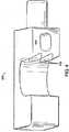
図1および図2は、本発明の開創器の一実施形態の一部分の2つの図面を例示している。部分100は、クリップブレード104が取り付けられたベース要素102を含む。ベース部分102は、ラチェットアーム106および受容孔108を含むコネクタの部分を含む。部分100はまた、ラチェット解除ボタン110を含む第2のベース要素に対して第1のベース要素の位置を固定するための機構の部品も含む。ラチェット解除ボタン110およびラチェットアーム106は、ピン112および114を含む取付け機構によってベース要素102に固定されている。ベース要素102は、取付け孔116を含む外科器具を支持するための取付け点を含む。開創器ブレード104は、基端部120から反対側の先端部122まで延在する主軸118を有する。開創器ブレード104は、基端部120をベース要素102に連結するクリップ124を含むブレード取付け機構を含む。ブレード104の内面と外面は共に、軸118に沿って弧状である。 1 and 2 illustrate two drawings of a portion of one embodiment of the retractor of the present invention.
図2は、図1に示されている角度とは異なる角度から見た部分的に分解された部分100を例示している。クリップ124を受容部126内をスライドさせて、ブレード104の基端部120をベース要素102に取り付けることができる。ピン112をピンホール128からベース102内に挿入し、ラチェット解除ボタン110の通路130内に通してラチェット解除ボタン110をベース要素102に固定する。図2に示されている図面は、ラチェットアーム106の内側の長さの一部に沿って延在する歯132を例示している。 FIG. 2 illustrates a partially exploded
一部の実施形態では、コネクタはラチェットアームを含む。例えば、第1のベース要素に取り付けられたラチェットアームを別のベース要素の受容孔の中に通して、第1のベース要素と第2のベース要素を取り付けることができる。第2のベース要素は、ラチェットアームの長さに沿って上流または下流にスライドして、ラチェットアームに対して移動し、そして第1のベース要素に対して移動することができる。固定機構により、ラチェットアームの位置を第2のベース要素に固定して、第1のベース要素と第2のベース要素が互いに対して移動しないようにする。 In some embodiments, the connector includes a ratchet arm. For example, a first base element and a second base element can be attached by passing a ratchet arm attached to the first base element through a receiving hole in another base element. The second base element can slide upstream or downstream along the length of the ratchet arm, move relative to the ratchet arm, and move relative to the first base element. A locking mechanism fixes the position of the ratchet arm to the second base element so that the first base element and the second base element do not move relative to each other.
図3‐図5は、第1のベース要素300、第2のベース要素500、および第1のベース要素の位置を第2のベース要素に対して固定するための機構の様々な部分を例示している。図3は、ラチェットアーム302、受容孔304、受容部306、およびラチェット解除ボタン400(図4に例示)を受容するボイド308を含む第1のベース要素300を例示している。ラチェット解除ボタン400は、歯402および通路404を含む。図5は、ラチェットアーム502、受容孔504、受容部506、およびラチェットアーム502上の歯508を含む第2のベース要素500を例示している。第1のベース要素を第2のベース要素に対して固定するための機構は、互いに相補的な歯402および歯508を含む。第1のベース要素300を第2のベース要素500に連結するために、ラチェットアーム502は、受容孔304内に案内される。 FIGS. 3-5 illustrate various portions of the
図4は、第1のベース要素300のラチェット解除ボタン400を例示している。ラチェット解除ボタン400の歯402は、歯508に相補的である。第1のベース要素300が第2のベース要素500から相対的に離れる移動をするときは、歯402と歯508が係合しないで、第1のベース要素300がラチェットアーム502の長さに沿って下流に移動できるように、歯402および/または歯508を配置することができる。すなわち、歯402と歯508は、第1のベース要素300が第2のベース要素500から離れる移動を比較的妨げないように配置されている。しかしながら、歯508と歯402は、第1のベース要素300と第2のベース要素500との間の距離が縮まる相対運動の場合は係合する。第1のベース要素300が第2のベース要素500に向かう相対運動は、ラチェット解除ボタン400を押して歯402を相補的な歯508から係合解除して行うことができる。歯402が歯508から係合解除されたら、第1のベース要素300が、所望の相対位置まで、第2のベース要素500に近づく方向に移動することができる。一部の実施形態では、ラチェット解除ボタンの歯および/またはラチェットアームの歯は、これらの歯が係合して1つのベース要素が別のベース要素から離れる相対運動を防止するように配置されている。別の実施形態では、歯は、1つのベース要素が別のベース要素から離れる相対運動を防止すると共に、1つのベース要素が別のベース要素に近づく相対運動も防止するように配置されている。 FIG. 4 illustrates the
図6‐図8は、3つの異なる位置すなわち拡張度合いにある本発明の開創器の一実施形態を例示している。図6は、完全に閉じた位置すなわち収縮した位置にある開創器700を例示している。開創器700は、4つの開創器ブレード702、704、706、および708と、主平面(XY平面に平行)を有する拡張可能なフレーム710を含む。開創器ブレード702、704、706、および708は、それぞれの基端部で拡張可能なフレーム710に取り付けられている。開創器ブレード702、704、706、および708は、弧状すなわち湾曲しており、この第1の位置では、これらの全ての内面が接触して、中空の円筒状の導管を画定している。 FIGS. 6-8 illustrate one embodiment of the retractor of the present invention in three different positions or degrees of expansion. FIG. 6 illustrates the
図6に例示されている収縮した位置では、拡張可能なフレーム710のベース要素714、716、718、および720によって画定されたアクセス口712の内径が、図7および図8に例示されている位置のアクセス口712の内径よりも小さい。これにより、最小の大きさの切開部を介して生物または外科手術患者(例えば、ヒトまたは他の哺乳動物)の体内に開創器700を挿入することができる。開創器700は、4つのラチェットアーム722、724、726、および728と、1つのベース要素の位置を別のベース要素に対して固定するための、ラチェット解除ボタン730、732、734、および736を含む機構を含む。 In the contracted position illustrated in FIG. 6, the inner diameter of the
開創器700は、主平面に対して実質的に垂直な少なくとも2つの平面によって二分されている。第1の平面は、XZ平面に平行であって、ベース要素714と716との間、およびベース要素718と720とので開創器700をほぼ二分する。第2の平面は、YZ平面に対して平行であって、ベース要素714と720との間およびベース要素716と718との間で開創器700をほぼ二分する。 The
図7は、部分的に拡張すなわち部分的に移動した位置にある開創器700を例示している。開創器700を図6に例示されている位置から図7に例示されている位置まで拡張するには、拡張可能なフレーム710に力を加えて、ベース要素714をラチェットアーム722に沿って移動させ、ベース要素718をラチェットアーム726に沿って移動させる。この方式では、拡張可能なフレーム710が、実質的に第1の平面に沿って第2の平面から概ね離れるように第1の位置(すなわち、図6に例示されている位置)から第2の位置(すなわち、図7に例示されている位置)まで主平面に平行またはほぼ主平面上を移動する。 FIG. 7 illustrates
ラチェットアーム722、724、726、および728は弧状である。ベース要素714、716、718、および720が弧状のラチェットアーム722、724、726、および728に沿って移動すると、開創器700が非対称または不均一に拡張または収縮する。すなわち、拡張可能なフレーム710が拡張すると、拡張可能なフレーム710の先端側のラチェットブレード702、704、706、および708の端部間の平均距離が、拡張可能なフレーム710の基端側の端部間の平均距離およびベース要素714、716、718、および720間の平均距離よりも大きくなる。外科手術に使用する際に、この不均一な拡張により、開創器ブレードの先端部が深い組織を開創させることができ、その一方で拡張可能なフレームを受容するのに必要な切開部の大きさを縮小させることができる。一部の実施形態では、ベース要素が移動しても、開創器が非対称または不均一に拡張または収縮しない。例えば、ラチェットアームが直線状の場合、拡張可能なフレームが拡張または収縮すると、ブレードの先端部が均一に拡張または収縮する。一部の実施形態では、所望の程度の非対称な拡張が得られるようにラチェットアームの形状を選択することができる。
ラチェットアーム722、724、726、および728の曲率により、拡張可能なフレーム710が拡張および収縮の様々な位置または程度まで移動すると、ベース要素714、716、718、および720が主平面からわずかにずれる。 The curvature of the
一部の実施形態(例えば、図6に示されている実施形態)では、ベース要素は、拡張可能なフレームが実質的に同一平面にあって主平面に平坦になるように配置されている。しかしながら、本発明は、拡張可能なフレームの1または複数の部分が、拡張および収縮の1または複数の位置または程度において実質的に同一平面にない実施形態も含む。 In some embodiments (eg, the embodiment shown in FIG. 6), the base elements are arranged such that the expandable frame is substantially coplanar and flat in the main plane. However, the invention also includes embodiments in which one or more portions of the expandable frame are not substantially coplanar at one or more positions or degrees of expansion and contraction.
図8は、拡張可能なフレーム710が図7に例示されている位置からさらに拡張した位置にある開創器700を例示している。図7に例示されている位置から図8に例示されている位置まで開創器700を拡張するには、拡張可能なフレーム710に力を加えて、実質的に主平面に沿って、ベース要素716をラチェットアーム724に沿って移動させ、ベース要素720をラチェットアーム728に沿って移動させる。この方式では、拡張可能なフレーム710は、第2の位置(すなわち、図7に示されている位置)から第3の位置(すなわち、図8に示されている位置)まで実質的に第2の平面に沿って第1の平面から概ね離れる方向に移動する。 FIG. 8 illustrates
所望に応じて、拡張可能なフレーム710は、1または複数のベース要素714、716、718、および720をそれぞれ、ラチェットアーム722、724、726、および728に沿って移動させて様々な異なった位置まで拡張または収縮させることができる。この方式では、開創器700を、様々な所望の位置まで拡張または収縮させることができる。 As desired, the
開創器700は、ラチェットアーム722、724、726、および728を含むコネクタを例示している。例えば、図7は、近接するベース要素718から部分的に延出したベース要素716のラチェットアーム726を例示している。同様に、ラチェットアーム724、722、および728が、ベース要素716、714、および720のそれぞれから部分的に延出している。この方式では、コネクタにより、ベース要素714、716、718、および720が連結されて拡張可能なフレーム710が形成される。 The
開創器700はまた、第1のベース要素の位置を第2のベース要素に対して固定するための機構を例示している。例えば、図7は、一連の歯または溝を含むラチェット解除ボタン734を例示している。この一連の歯または溝は、ラチェットアーム726上の第2の一連の相補的な歯または溝に係合して、ベース要素718の位置をラチェットアーム726に対して固定する。したがって、ラチェット解除ボタン734により、ベース要素716(すなわち、「第1のベース要素」)の位置がベース要素718(すなわち、「第2のベース要素」)に対して固定される。ラチェット解除ボタン734を押すと相補的な歯が係合解除され、ベース要素718はラチェットアーム726に沿って移動することができ、ベース要素718はベース要素716に対して移動する。同様に、ベース要素714に対するベース要素716の位置も、ラチェット解除ボタン732を係合または係合解除して調節することができ、ベース要素720に対するベース要素714の位置も、ラチェット解除ボタン730を係合または係合解除して調節することができ、ベース要素718に対するベース要素720の位置も、ラチェット解除ボタン736を係合または係合解除して調節することができる。 The
開創器700を図8に例示されている位置から図7に例示されている位置まで調節するために、ラチェット解除ボタン736および732を押して、拡張可能なフレーム710を、第2の平面に沿って概ね第1の平面に向かって移動させることができる。同様にラチェット解除ボタン734および730を用いて、拡張可能なフレーム710を第1の平面に沿って概ね第2の平面に向かって移動させて調節することができる。この方式では、拡張可能なフレーム710を1または複数の異なる位置に調節することができ、これにより、開創器700を所望の程度に拡張または収縮させることができる。 To adjust the
一部の実施形態では、拡張可能なフレームは、2つ以上のベース要素を取り付ける1または複数の蝶番を備えたコネクタを含む。図9‐図12は、開創器900の4つの異なる図面を例示している。開創器900は、拡張可能なフレーム910に取り付けられた開創器ブレード902、904、906、および908を含む。拡張可能なフレーム910は、ベース要素912、914、916、および918を含む。各ベース要素912、914、916、および918は、各開創器ブレード902、904、906、および908をそれぞれ含む連続的な一片の材料から製造または形成する。拡張可能なフレーム910は、ベース要素918に取り付けられたラチェットアーム920、およびベース要素916に取り付けられたラチェットアーム922を含む。ラチェットアーム920は、ベース要素918からベース要素912の受容孔内に延在し、ベース要素918をベース要素912に連結している。同様に、ラチェットアーム922は、ベース要素916をベース要素914に連結している。開創器900は、ラチェット解除レバー924および926を備えた、第1のベース要素の位置を第2のベース要素に対して固定するための機構を含む。ラチェット解除レバー924および926は、既に例示したラチェット解除ボタンと同じ機能を果たし、ラチェットアーム922に対するベース要素914の位置、およびラチェットアーム920に対するベース要素912の位置を固定解除するために用いる。 In some embodiments, the expandable frame includes a connector with one or more hinges that attach two or more base elements. 9-12 illustrate four different views of the
拡張可能なフレーム910は、蝶番927および928を備えたコネクタも含む。蝶番927は、ベース要素912をベース要素914に回動可能に連結し、蝶番928は、ベース要素916をベース要素918に回動可能に連結している。開創器900は、レバー930および932を備えた、第1のベース要素の位置を第2のベース要素に対して固定するための機構も含む。レバー930は、蝶番927の回動をロックまたは固定して、ベース要素914に対してベース要素912の位置を固定する。レバー932は、蝶番928の回動をロックまたは固定して、ベース要素916に対してベース要素918の位置を固定する。拡張可能なフレーム910は、アクセス口934を画定している。 The
図10は、拡張可能なフレーム910が図9に例示されている第1の位置から第2の位置に移動した後の開創器900の平面図を例示している。ラチェットアーム920および922はそれぞれ、実質的に直線状であって、ベース要素918に対するベース要素912の移動、およびベース要素916に対するベース要素914の移動を可能にする。ラチェットレバー926は、ラチェット920の一側の歯936に係合して、ベース要素912に対してベース要素918の位置を固定する。同様に、ラチェットレバー924は、ラチェットアーム922の一側の歯938に係合して、ベース要素914に対してベース要素916の位置を固定する。 FIG. 10 illustrates a plan view of the
図11は、拡張可能なフレーム910が、蝶番927および蝶番928(図11には不図示)を中心とした回動により第2の位置から第3の位置に移動した後の開創器900の側面図を例示している。蝶番927および928により、ベース要素914および916をベース要素912および918に対して移動させることができる。この回動により、開創器ブレード902と904の先端部間の平均距離が、開創器ブレード902と904の2つの基端部間の平均距離、および2つのベース要素912と914との間の平均距離よりも大きくなる。図12は、拡張可能なフレーム910が第3の位置に移動した後の開創器900の別の図面を例示している。 FIG. 11 shows the side of the
オプションとして、開創器の1または複数のブレードは、ブレードに伸縮自在およびスライド可能に取り付けられた1または複数のブレード延長部を含む。一部の実施形態では、開創器は、係合すると所望の伸縮長さにブレード延長部を静止すなわち固定するブレード延長部固定機構を含む。ブレード延長部固定機構の一例として、延長部をブレードにスライド可能に固定する、ブレード上および/またはブレード延長部上の1または複数の一連の歯またはリッジを挙げることができる。別の例のブレード延長部固定機構は、ブレード上の一連の歯とブレード延長部上のタブを含む。このタブがブレード上の歯に係合して、ブレード延長部を固定する。タブに力を加えると、タブが歯から係合解除され、ブレード延長部がブレードに対してスライド可能になる。フック、レバー、ラッチ、ねじ、ロック機構、およびこれらの組合せなどの様々な他のブレード延長部固定機構も本発明に包含される。加えて、ブレード延長部固定機構は、1または複数の電動ねじなどの自動機構を含むことができる。 Optionally, one or more blades of the retractor includes one or more blade extensions that are telescopically and slidably attached to the blade. In some embodiments, the retractor includes a blade extension locking mechanism that when engaged engages the blade extension at a desired telescopic length. An example of a blade extension fixing mechanism may include one or more series of teeth or ridges on the blade and / or on the blade extension that slidably fix the extension to the blade. Another example blade extension locking mechanism includes a series of teeth on the blade and a tab on the blade extension. This tab engages the teeth on the blade to secure the blade extension. Applying force to the tab disengages the tab from the teeth and allows the blade extension to slide relative to the blade. Various other blade extension securing mechanisms such as hooks, levers, latches, screws, locking mechanisms, and combinations thereof are also encompassed by the present invention. In addition, the blade extension securing mechanism can include an automatic mechanism, such as one or more electric screws.
オプションとして、開創器は、ブレード延長部がブレードに対して移動する時にブレード延長部がブレードから外れるのを防止する機構を含む。このような機構の一例として、ブレード延長部をブレードにスライド可能に固定するブレード上および/またはブレード延長部上の1または複数の溝または通路を挙げることができる。この溝により、ブレード延長部がブレードに対してスライドすることができ、かつブレード延長部がブレードから外れるのが防止される。ブレード延長部がブレードから外れるのを防止する様々な他の機構も本発明に包含される。 Optionally, the retractor includes a mechanism that prevents the blade extension from detaching from the blade as the blade extension moves relative to the blade. An example of such a mechanism may include one or more grooves or passages on the blade and / or on the blade extension that slidably secures the blade extension to the blade. This groove allows the blade extension to slide relative to the blade and prevents the blade extension from coming off the blade. Various other mechanisms for preventing the blade extension from coming off the blade are also encompassed by the present invention.
オプションとして、ブレード延長部は、ブレード延長部の伸縮動作を容易にする伸縮取付け点を供する伸縮タブを含む。 Optionally, the blade extension includes a telescoping tab that provides a telescoping attachment point that facilitates telescoping movement of the blade extension.
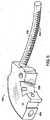
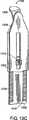
図13A‐図13Cに、伸縮長さが段階的に長くなったブレード1300の先端部1304から延びたブレード延長部1302を備えたブレード1300の内面が例示されている。ブレード1300は、クリップ1306を含む取付け機構を基端部1308に備えている。ブレード1300は、ブレード延長部1302の全長の少なくとも一部に亘って延在する2つの連続した歯1310を備えたブレード延長部固定機構を含む。相補的な連続的な歯が、歯1310の両方の通路に強制的に係合されて、ブレード延長部1302が所望の伸縮長さに維持される。ブレード延長部1302は、ブレード1300の内面の開口部から延出している伸縮取付け点1312を含む。 13A to 13C illustrate the inner surface of the
オプションとして、1または複数のブレードおよび/またはブレード延長部は、外面の先端部から延びたトウアウト突出部を含む。図14は、ブレード延長部1302の外面の先端部1314の拡大図を例示している。トウアウト突出部1314は、ブレード延長部1302の外面から延出している。トウアウト突出部1314により、ブレード延長部1302は、トウアウト突出部を備えていない類似のブレード延長部に比べ、手術部位から組織をより効率的に開創することができる。ブレード延長部1302は、その全長の少なくとも一部に亘って延在するリッジ1316も含み、リッジを備えていない類似のブレード延長部に比べ、手術部位から組織をより効率的に開創することができる。別の実施形態では、トウアウト突出部は、ブレードまたはブレード延長部の表面から所定の角度(例えば、直角、90度超、または90度未満)で延出している。 Optionally, the one or more blades and / or blade extensions include toe-out protrusions extending from the outer surface tip. FIG. 14 illustrates an enlarged view of the
一部の実施形態では、1または複数のブレードおよび/またはブレード延長部の外面は、ブレードまたはブレード延長部が組織を保持するのに役立つ凹凸面を含む。これにより、手術部位における組織の開創が改善される。例えば、外面の複数部分が、粗い凹凸、リッジ(例えば、図14に示されているリッジ)、または類似の表面凹凸を有することができる。 In some embodiments, the outer surface of the one or more blades and / or blade extensions includes an uneven surface that helps the blades or blade extensions hold tissue. This improves tissue retraction at the surgical site. For example, portions of the outer surface can have rough irregularities, ridges (eg, the ridge shown in FIG. 14), or similar surface irregularities.
図15は、ブレード延長部を含む本発明の開創器の実施形態を例示している。開創器1500は、ベース要素1504、1506、1508、および1510間の平均距離が最大である完全に拡張した位置にある拡張可能なフレーム1502を含む。ブレード1512、1514、1516、および1518はそれぞれ、ブレード延長部1520、1522、1524、および1526を含む。図15は、ブレード延長部1520、1522、1524、および1526がそれぞれ、ブレード1512、1514、1516、および1518から延出していない拡張位置にある拡張可能なフレーム1502を例示している。 FIG. 15 illustrates an embodiment of the retractor of the present invention that includes a blade extension. The
図16Aは、開創器1600を含む本発明の別の実施形態を例示している。開創器1600は、拡張可能なフレーム1602(図15に例示されている拡張可能なフレーム1502よりもわずかに拡張していない位置にある)と、ブレード1612、1614、1616、および1618のそれぞれから部分的に延出したブレード延長部1620、1622、1624、および1626を含む。開創器1600は、アーム1638、1640、1642、および1644を含む複数のコネクタも含む。 FIG. 16A illustrates another embodiment of the present invention that includes a
図16Bは、拡張可能なフレーム1602が収縮すなわち閉じた位置にあり、延長部1620、1622、1624、および1626がそれぞれ、ブレード1612、1614、1616、および1618から部分的に延出した開創器1600を例示している。開創器1600は、取付け点すなわち孔1630、1632、1634、および1636を含む複数の自在取付け点を含む。取付け孔1630、1632、1634、および1636を用いて、外科器具、追加ブレード、開創器支持構造(例えば、硬質アーム)などを取り付けることができる。 FIG. 16B shows
図16Cは、要素1608、延長部1624、およびアーム1644を含む開創器1600の一部の斜視図を例示している。図16Dは、要素1608および延長部1624を含む開創器1600の一部の別の斜視図を例示している。 FIG. 16C illustrates a perspective view of a portion of a
図16Eは、要素1608、ブレード1616、およびアーム1644を含む開創器1600の一部のさらに別の斜視図を例示している。図16Eに示されている斜視図では、延長部1624は、ブレード1616から取り外されている。 FIG. 16E illustrates yet another perspective view of a portion of
図16Fは、図16Eに例示されている開創器1600の一部の組立分解図を含む開創器1600の一部の斜視図を例示している。ラチェットアーム解除ボタン1662が、ピン1656を用いてベース要素1608に取り付けられる。ばね1652が、アーム1642(図16Fには不図示)に係合するのに十分な力を加えているため、外科医がボタン1662を押圧しない限り、アーム1642に対してベース要素1608が移動しない。開創器1600は、アーム上とボタン上の相互的な歯の傾斜により、ボタンを押さなくても自由に拡張できる。開創器1600を閉じるすなわち収縮させるには、本発明の実施者がボタンを押して、アームとボタンの歯の係合を解除する。アーム1644は、ピン1654でベース要素1608に固定されている。ラチェットアーム1644は、歯1650を含むベース要素1608の相対位置を固定するための機構の一部を含む。 FIG. 16F illustrates a perspective view of a portion of the
一部の実施形態では、本発明の開創器のコネクタが、追加の外科器具および/または開創器ブレードのための取付け点としての機能を果たす。図16Gは、ブレード1670を含む開創器1600の別の斜視図を例示している。台形型のブレード1670が、アーム1642に取付けまたは組み付けられている。ハンドル1672を用いて、ブレード1670を開創器1600に組み付ける。本発明の実施者は、アーム1672を用いて、ブレード1670を取付け点1632(図16Gには不図示)で開創器1600に組み付ける。 In some embodiments, the retractor connector of the present invention serves as an attachment point for additional surgical instruments and / or retractor blades. FIG. 16G illustrates another perspective view of a
ブレード1670は、台形の形状を含むが、本発明の開創器のブレードは、当分野で周知のブレードの形態または形状を含みうることを理解されたい。図16Hおよび図16Iは、アーム1676および1678のそれぞれに取り付けまたは組み付けられる2つの代替のブレード1672および1674を例示している。 Although
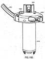
一部の実施形態では、本発明の開創器を所望の位置に案内するために挿入器を用いる。図16Jは、挿入器1680を含む本発明の一部を例示している。挿入器1680は、複数の取付けピン1682を含む。取付けピン1682により、挿入器1680を本発明の開創器のフレームの取付け孔の一部または全てに固定する。本発明の実施者は、本発明の開創器に挿入器1680を組み付けまたは取り付けて、ハンドル1684を用いて、哺乳動物の解剖学的構造の所望の位置に開創器1600を配置または案内する。 In some embodiments, an inserter is used to guide the retractor of the present invention to a desired location. FIG. 16J illustrates a portion of the present invention that includes an inserter 1680. The inserter 1680 includes a plurality of mounting
図16Kおよび図16Lは、伸縮ブレードエクステンダー1886の斜視図を例示している。伸縮ブレードエクステンダー1886は、先端部1888および基端部1890を含む。実施者は、基端部1890を用いて、ブレード延長部1620、1622、1624、および/または1626をブレード1612、1614、1616、および1618に対してスライドさせて、それぞれ哺乳動物の解剖学的構造の所望の位置に配置する。 16K and 16L illustrate perspective views of the
図16Mは、伸縮ブレードリムーバー1892の斜視図を例示している。伸縮ブレードリムーバー1892は、先端部1896および基端部1894を含む。実施者は、基端部1894を用いてブレード延長部をつかみ、ブレード延長部を哺乳動物の解剖学的構造から係合解除し、かつ/または哺乳動物の解剖学的構造の所望の位置にブレード延長部を再配置する。 FIG. 16M illustrates a perspective view of the
本発明のブレードおよびブレード延長部は、あらゆる所望の形状および大きさを有することができる。一部の実施形態では、1または複数のブレードまたはブレード延長部は、その形状および/または大きさを特定の用途に合わせることができる。例えば、ブレードは、筋組織、脂肪組織、神経組織、または他のタイプの組織を開創するための形状にすることができる。図17A‐図17Cに、異なる台形形状の様々なブレードの例が例示されている。図17A‐図17Cに例示されているブレードは、台形形状のほんのわずかな例であり、本発明は、様々な異なるブレード形状(例えば、非台形形状のブレード)を含む。 The blades and blade extensions of the present invention can have any desired shape and size. In some embodiments, one or more blades or blade extensions can be tailored in shape and / or size to a particular application. For example, the blade can be shaped to retract muscle tissue, adipose tissue, nerve tissue, or other types of tissue. 17A-17C illustrate examples of various blades with different trapezoidal shapes. The blades illustrated in FIGS. 17A-17C are just a few examples of trapezoidal shapes, and the present invention includes a variety of different blade shapes (eg, non-trapezoidal blades).
オプションとして、本発明の開創器は、ブレードまたはブレード延長部の先端部に追加の延長部を含む。図17Dは、蝶番1704を中心に回動する旋回延長部1702を含むブレード1700の先端部を例示している。図17Eおよび図17Fは、追加ブレード延長部の別の実施形態を例示している。ブレード1750の先端部には、2つの追加延長部1752がスライド1754によってスライド可能に取り付けられている。オプションとして、追加の延長部を所望の位置に固定可能である。 Optionally, the retractor of the present invention includes an additional extension at the tip of the blade or blade extension. FIG. 17D illustrates the tip of a
オプションとして、1または複数の外科器具を開創器に取り付けて、別の有用性を付与することができる。このような外科器具の例として、外科手術用光源、吸引源の一部、または当分野で周知の他の外科器具を挙げることができる。一部の実施形態では、外科器具は、その外科器具を支持する機構を備えた拡張可能なフレームに取り付ける。外科器具は、開創器の拡張前、拡張中、または拡張後に取り付けることができる。一部の実施形態では、ブレードまたはブレード延長部の内面または外面は、長手方向の溝または通路を含む。この長手方向の溝または通路を用いて、外科器具をブレードまたはブレード延長部の全長に沿って手術部位またはその近傍にスライドまたは他の方法で移動させることができる。 Optionally, one or more surgical instruments can be attached to the retractor to provide additional utility. Examples of such surgical instruments can include a surgical light source, a portion of a suction source, or other surgical instruments known in the art. In some embodiments, the surgical instrument is attached to an expandable frame that includes a mechanism for supporting the surgical instrument. The surgical instrument can be attached before, during, or after expansion of the retractor. In some embodiments, the inner or outer surface of the blade or blade extension includes a longitudinal groove or passage. This longitudinal groove or passage can be used to slide or otherwise move the surgical instrument along or along the entire length of the blade or blade extension to or near the surgical site.
図18は、拡張可能なフレーム1802を含む開創器1800を例示している。拡張可能なフレーム1802は、ベース要素1804、1806、1808、および1810を含む。ベース要素1804、1806、および1810はそれぞれ、取付け孔1812、1814、および1816を画定している。光源1818が、ベース要素1808の取付け孔に外科用クリップ1820を含む外科器具を支持するための機構を用いてベース要素1808に取り付けられている。 FIG. 18 illustrates a
図19は、拡張可能なフレーム1902を含む開創器1900を例示している。拡張可能なフレームは、ベース要素1904、1906、1908、および1910を含む。ベース要素1904、1906、1908、および1910は、取付け孔1912を画定している。取付け孔1912により、外科用クリップ1914および1916の取付け部位が画定されている。外科用クリップ1914および1916により、外科手術用光源1918などの器具を拡張可能なフレームに固定することができる。 FIG. 19 illustrates a
一部の実施形態では、追加ブレードが、別の有用性を得るために開創器に取り付けられている。図20は、ベース要素2002および2004を含む開創器2000への追加ブレードの取付けを例示している。ベース要素2002および2004は、ラチェットアーム2008などの露出したラチェットアームに沿って拡張可能なフレーム2006に取り付けられている。ベース要素2004は、ブレード2010およびラチェット解除ボタン2012を含む。ラチェット解除ボタン2012により、ベース要素2004がラチェットアーム2008に対して相対位置に固定されている。 In some embodiments, additional blades are attached to the retractor for additional utility. FIG. 20 illustrates the attachment of an additional blade to a
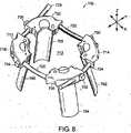
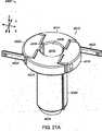
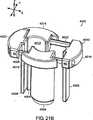
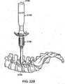
図21A‐図21Dは、本発明の開創器のさらに別の実施形態である開創器4000を例示している。図21Aは、開創器が完全に閉じたすなわち収縮した第1の位置にある開創器4000を例示している。図21Bは、開創器が拡張または開いた第2の位置にある開創器4000を例示している。図21Cは、第2の位置にある開創器4000の別の図を例示している。図21Dは、第2の位置にある開創器4000の底面図を例示している。 21A-21D illustrate a
開創器4000は、XY平面に平行な主平面を有する拡張可能なフレーム4010を含む。拡張可能なフレーム4010は、第1のベース要素4014、第2のベース要素4016、第3のベース要素4018、および第4のベース要素4020を含む。開創器4000は、4つのベース要素を有するとして図21A‐図21Dに例示されているが、別の実施形態では、開創器は、2つ、3つ、または5つ以上のベース要素を含むことができる。オプションとして、開創器4000は、外科器具を支持するための少なくとも1つの機構を含む(図21A‐図21Dには不図示)。外科器具を支持するための好適な機構の例として、図1、図2、および図18に例示したものと同様の外科用クリップ、または取付け溝などの上記した機構を挙げることができる。 The
ベース要素4014、4016、4018、および4020は、2つのロッド4022および4024を含むコネクタを用いて互いに連結されている。ロッド4022は、第1のベース要素4014と第2のベース要素4016と第4のベース要素4020を連結し、ロッド4024は、第2のベース要素4016と第3のベース要素4018と第4のベース要素4020を連結している。ロッド4022および4024はそれぞれ、第1のベース要素4014および第3のベース要素4018を完全に貫通している。図21Aに例示されている位置では、ロッド4022および4024はそれぞれ、第2のベース要素4016および第3のベース要素4020を完全に貫通している。ベース要素4016および4020は、ロッド4022および4024の長さに沿って移動することができる。ベース要素4014は、ロッド4022の長さに沿って移動することができ、ベース要素4018は、ロッド4024の長さに沿って移動することができる。
開創器はまた、1つのベース要素(図21A‐図21Dには不図示)の位置を別の要素に対して固定するための1または複数の機構を含む。1つのベース要素の位置を別のベース要素に対して固定するための好適な機構の例は、ここに開示しており、図1‐図3、図6‐図8、および図9‐図12に例示されている1つのベース要素の位置を別のベース要素に対して固定するための機構、ならびに他のラチェット、ねじ、または保持機構が含まれる。 The retractor also includes one or more mechanisms for fixing the position of one base element (not shown in FIGS. 21A-21D) relative to another element. Examples of suitable mechanisms for fixing the position of one base element relative to another base element are disclosed herein and are shown in FIGS. 1-3, 6-8, and 9-12. Includes a mechanism for fixing the position of one base element relative to another base element as well as other ratchets, screws, or retention mechanisms.
開創器4000は、ベース要素4016、4018、4014、および4020のそれぞれに取り付けられた開創器ブレード4002、4004、4006、および4008を含む。開創器ブレード4002、4004、4006、および4008は、弧状すなわち湾曲しており、図21Aに例示されている第1の位置では、これらの全ての内面が接触し、これにより平滑すなわち実質的に継ぎ目のない外径を有する中空の円筒状の導管を画定している。一部の実施形態では、この導管は、楕円筒状にすることができる。 The
一部の実施形態では、開創器4000の少なくとも一部が、放射線透過性材料を含む。例えば、開創器の一部は、放射線透過性のプラスチック、アルミニウム、薄いステンレス鋼、チタン、ニチノール、またはコバルトクロムを含むことができる。 In some embodiments, at least a portion of the
オプションとして、開創器ブレードは、一体型のスリーブインサートを含むことができる。例えば、開創器ブレードは、その開創器ブレードに伸縮自在かつスライド可能に取り付けられているブレード延長部を含むことができる。開創器はまた、係合するとブレード延長部を開創器ブレードの残りの部分に対して固定するブレード延長部固定機構を含むこともできる。ブレード延長部および固定機構の例は、図13A‐図13C、図16、および図17D‐図17Fに例示し、開示している。 Optionally, the retractor blade can include an integral sleeve insert. For example, the retractor blade can include a blade extension that is telescopically and slidably attached to the retractor blade. The retractor can also include a blade extension locking mechanism that, when engaged, locks the blade extension to the rest of the retractor blade. Examples of blade extensions and locking mechanisms are illustrated and disclosed in FIGS. 13A-13C, 16, and 17D-17F.
一部の実施形態では、1または複数の開創器ブレードが、組織を保持して組織を良好に開創できるようにトウアウト突出部を有する。このようなトウアウト突出部の例は、例えば、図14に例示し、開示している。 In some embodiments, one or more retractor blades have toe-out protrusions to hold the tissue and better retract the tissue. An example of such a toe-out protrusion is illustrated and disclosed, for example, in FIG.
開創器ブレード4002、4004、4006、および4008の主軸は、拡張可能なフレームの主平面に対して垂直である。一部の実施形態では、1または複数のブレードが、ブレードの主軸を中心に回動でき、かつ主軸を中心とした所望の回動点で固定できるように拡張可能なフレームに取り付けられている。例えば、ブレードは、このブレードの横方向への回動を可能にする垂直の蝶番を用いてベース要素に取り付けることができる。別の実施形態では、1または複数のブレードが、拡張可能なフレームの主平面に対して平行な軸を中心にこのブレードが回動できるように拡張可能なフレームに取り付けられている。例えば、ブレードは、このブレードの上方および下方への回動を可能にする水平の蝶番を用いてベース要素に取り付けることができる。 The main axes of the
開創器4000は、主平面XYに対して実質的に垂直な少なくとも2つの平面によって二分されている。第1の平面は、XZ平面に平行であって、開創器4000を二分しており、ベース要素4014と4018とのほぼ中間に延在し、ベース要素4016と4020を二分している。第2の平面は、YZ平面に平行であって、開創器4000を二分しており、ベース要素4016と4020とのほぼ中間に延在し、ベース要素4014と4018を二分している。 The
図21Aに例示されている収縮した位置では、拡張可能なフレーム4010のベース要素4014、4016、4018、および4020によって画定されているアクセス口4012の内径は、図21B‐図21Dに例示されている位置のアクセス口4012の内径よりも小さい。これにより、最小サイズの切開部を介して生物または外科手術患者(例えば、ヒトまたは他の哺乳動物)の体内に開創器4000を挿入することができる。 In the contracted position illustrated in FIG. 21A, the inner diameter of the
開創器4000が所望の解剖学的構造の位置に挿入されたら、開創器4000を拡張すなわち配置することができる。例えば、拡張器具(図26‐図28に例示されている拡張器具など)を用いて、開創器ブレードの先端部を開くことができる。開創器4000を用いて、最大筋力に対して概ね垂直な角度で筋肉を開創して保持し、これにより解剖学的な拘束によって開創器ブレードの良好または最適な配置が可能となり、作業通路によって拘束されていない筋肉または他の組織によって引き起こされる組織のクリープに関連した問題が軽減される。 Once the
図21Bは、部分的に拡張した位置すなわち部分的に移動した位置にある開創器4000を例示している。開創器4000を図21Aに例示されている位置から図21Bに例示されている位置まで拡張するには、拡張可能なフレーム4010に力を加えて、ベース要素4016をロッド4022に沿って、ベース要素4020およびロッド4024に対して移動させる。ロッド4022および4024の端部に位置するストッパー(不図示)が、取り付けられた要素が端部から移動してロッドから外れるのを防止している。ベース要素4014および4018はそれぞれ、ロッド4022または4024に沿って所望の位置にスライド可能に配置することができる。この方式では、拡張可能なフレーム4010は、実質的に第1の平面に沿って第2の平面から概ね離れる方向に第1の位置(すなわち、図21Aに例示されている位置)から第2の位置(すなわち、図21Bに例示されている位置)までほぼ主平面上またはその主平面に平行に移動する。オプションとして、開創器ブレードを備えたまたは備えていない追加のベース要素をロッド4022および4024に固定することができる。 FIG. 21B illustrates the
所望に応じて、拡張可能なフレーム4010は、1または複数のベース要素4014、4016、4018、および4020をロッド4022および4024の一方に沿って移動させて様々な異なる位置まで拡張または収縮させることができる。この方式では、開創器4000を、様々な所望の位置まで拡張または収縮させることができる。 As desired, the
図示されているロッド4022および4024は、直線状であるため、ベース要素が移動しても、開創器が非対称または不均一に拡張または収縮しない。言い換えれば、拡張可能なフレームの拡張または収縮により、ブレードの先端部が均一に拡張または収縮し、ベース要素は、互いに対して同一平面上に維持され、主平面XYに平坦に配置される。 The illustrated
別の実施形態では、ロッドまたは他のコネクタの形状は、拡張可能なフレームが第2の位置にあるときに任意の2つのブレードの先端部間の最大距離よりも小さい平均直径を有するアクセス口を拡張可能なフレームが画定するように、所望の程度に非対称または湾曲した拡張が得られるように選択される。一部の実施形態では、拡張可能なフレームの1または複数の部分が、拡張および収縮の1または複数の位置すなわち程度において、実質的に同一平面にない。 In another embodiment, the shape of the rod or other connector provides an access port having an average diameter that is less than the maximum distance between the tips of any two blades when the expandable frame is in the second position. As the expandable frame defines, it is selected to obtain an expansion that is as asymmetrical or curved as desired. In some embodiments, one or more portions of the expandable frame are not substantially coplanar at one or more positions or degrees of expansion and contraction.
一部の実施形態では、ブレードおよび/またはブレード延長部が、拡張可能なフレームが1または複数の位置にあるときに、拡張可能なフレームに追加の構造的強度を付与する。例えば、インターロックするブレードまたはブレード延長部を、それらの縁または側面の一部に沿って互いに機械的に連結して追加の構造的強度を付与することができる。 In some embodiments, the blades and / or blade extensions provide additional structural strength to the expandable frame when the expandable frame is in one or more positions. For example, interlocking blades or blade extensions can be mechanically coupled to each other along portions of their edges or sides to provide additional structural strength.
本発明の開創器は、様々なポリマー、金属(例えば、チタン)、および金属合金(例えば、ステンレス鋼、コバルトクロム、およびチタン合金など)を含め、様々なタイプの材料から構成することができる。開創器のある部分(例えば、ベース、ラチェットアーム、および拡張可能なフレームの蝶番)には、強い硬質材料が必要であろう。開創器の他の部分(例えば、固定機構の可撓性タブ)には、繰り返しの変形に耐えるために耐久性のある可撓性材料が必要であろう。製造材料は、生体適合性であるのが好ましい。 The retractor of the present invention can be constructed from various types of materials, including various polymers, metals (eg, titanium), and metal alloys (eg, stainless steel, cobalt chrome, titanium alloys, etc.). Certain parts of the retractor (eg, base, ratchet arm, and expandable frame hinge) may require strong rigid materials. Other parts of the retractor (e.g., the flexible tab of the fixation mechanism) may require a durable flexible material to withstand repeated deformation. The manufacturing material is preferably biocompatible.
加えて、製造材料は、外科手術のある部分で好ましい特性または別の利点を付与するように選択することができる。例えば、外科手術中に患者のX線イメージおよび/または蛍光イメージを撮る必要がある場合が多い。したがって、一部の実施形態では、開創器の少なくとも一部を放射線透過性材料から構成される。しかしながら、X線イメージ上にマーカー基準点を設けるのが有利であろう。したがって、別の実施形態では、開創器の少なくとも一部が、放射線不透過性材料から形成される。 In addition, the manufacturing material can be selected to provide favorable properties or other advantages in certain parts of the surgery. For example, it is often necessary to take an x-ray image and / or a fluorescent image of a patient during surgery. Thus, in some embodiments, at least a portion of the retractor is constructed from a radiolucent material. However, it may be advantageous to provide a marker reference point on the x-ray image. Thus, in another embodiment, at least a portion of the retractor is formed from a radiopaque material.
一部の実施形態では、本発明は、生物(例えば、ヒトまたは他の哺乳動物)に手術部位を形成する方法を含む。一実施形態では、この方法は、(a)哺乳動物の皮膚に切開部を作り出すステップと、(b)本発明の開創器を用いて切開部の哺乳動物の組織を開創して手術部位を形成するステップと、を含む。 In some embodiments, the invention includes a method of forming a surgical site in an organism (eg, a human or other mammal). In one embodiment, the method comprises: (a) creating an incision in the mammalian skin; and (b) using the retractor of the present invention to open the mammalian tissue in the incision to form a surgical site. Including the steps of:
一部の実施形態では、手術部位は、脊柱に形成される。別の実施形態では、手術部位は、経椎間孔腰椎椎体間固定術(transforaminal lumbar interbody fusion procedure)、後方進入腰椎椎体間固定術、後側方固定術、および他の外科手術(例えば、頚部または胸部などの前方、後方、前方外側、および他の脊椎の領域)からなる群の少なくとも1つを含む外科手術の際に形成される。本発明の開創器は、脊椎外科手術以外の外科手術での使用にも適している。 In some embodiments, the surgical site is formed in the spinal column. In another embodiment, the surgical site may be a transforaminal lumbar interbody fusion procedure, posterior approach lumbar interbody fusion, posterior lateral fusion, and other surgical procedures (e.g., , Anterior, posterior, anterior lateral, and other spinal regions such as the cervix or chest). The retractor of the present invention is also suitable for use in surgical procedures other than spinal surgery.
一部の実施形態では、開創器を挿入する前に、オブチュレータを切開部内に挿入する。別の実施形態では、開創器を挿入する前に、1つのオブチュレータとそれに続く拡張器を挿入して切開部を拡張する。 In some embodiments, the obturator is inserted into the incision prior to inserting the retractor. In another embodiment, before inserting the retractor, an obturator followed by a dilator is inserted to expand the incision.
オプションとして、開創器は、生物の体内に挿入される前に挿入チューブに組み付けられる。挿入チューブにより、生物の体内への開創器の挿入および配置が容易になる。一部の実施形態では、挿入チューブは、開創器の拡張可能なフレームに取り付けられる。 Optionally, the retractor is assembled to the insertion tube before being inserted into the organism. The insertion tube facilitates insertion and placement of the retractor into the organism. In some embodiments, the insertion tube is attached to the expandable frame of the retractor.
一部の実施形態では、形成する手術部位の深さまたはその近傍まで開創器を挿入するときに、開創器をオブチュレータ上に配置する。図22A‐図22Hは、ヒトの脊椎の近傍組織を開創するために用いられるこのような方法の一実施形態を例示している。見やすくするために、軟組織および一部の骨部分を図面から省略している。 In some embodiments, the retractor is placed on the obturator when the retractor is inserted to or near the depth of the surgical site to be formed. 22A-22H illustrate one embodiment of such a method used to retract tissue adjacent to the human spine. For ease of viewing, soft tissue and some bone portions are omitted from the drawing.
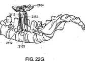
図22Aは、切開部内に挿入され、手術部位(すなわち、脊柱の隣)まで押し込まれたオブチュレータ2100を例示している。オプションとして、オブチュレータを、手術部位に既に繋がれているガイドワイヤに沿って案内する。 FIG. 22A illustrates
オブチュレータ2100が手術部位2102に配置されたら、開創器2104を挿入チューブ2106に取り付ける。開創器2104と挿入チューブ2106の組立体が、オブチュレータ2100の外径よりも大きい内径を有する導管を画定する。これにより、開創器2104と挿入チューブ2106の組立体を、図22Bに示されているようにオブチュレータ2100上に取り付けることができる。 Once the
開創器2104がオブチュレータ2100上に取り付けられたら、外科医またはこの実施形態の別の実施者が、図22Cに示されているように、挿入チューブ2106に力を加えて開創器2104をオブチュレータ2100の長さに沿って手術部位2102まで押し込む。開創器2104が手術部位2102に到達したら、オブチュレータ2100を切開部から取り出し、図22Dに示されているように、挿入チューブ2106に取り付けられた開創器2104を切開部に残す。 Once
外側スリーブ2110がフレームに接触しており、これを用いて開創器2104を所望の深さおよび位置(例えば、ブレード延長部の延出のために十分な空間が得られるように手術部位またはその上)に配置する。別法またはこれに加えて、外側スリーブ2110は、開創器2104の基端部のアリ構造内に挿入されたブレードの基端部を保持する。内側スリーブ2108を用いて、ブレードおよび/またはブレード延長部を開創器に挿入するか、または1または複数のブレード延長部を所望の程度に延出させる。別法またはこれに加えて、内側スリーブ2108を用いて、ブレードの先端部を保持して、切開部に挿入するときにブレードが開くのを防止する。ブレードおよび/またはブレード延長部は、任意の所望の順序または組合せで挿入または配置することができる(例えば、全てのブレードまたは延長部を同時または別々に挿入または配置する)。次いで、図22Eに示されているように、内側スリーブ2108を挿入チューブ2106から取り外し、次いで、図22Fに示されているように、外側スリーブ2110を取り外す。 An
挿入チューブ2106の全ての部分が開創器2104から取り外されたら、図22Gに示されているように、1または複数のブレード延長部2112を、手術部位2102周囲の所望の部位まで延出させることができる。図22Gに示されているように、ブレード延長部2112は、開創器2104のブレードの外面に取り付けられているが、一部の実施形態では、ブレード延長部は、ブレードの内面に取り付けられる。 Once all portions of the
最後に、開創器2104の拡張可能なフレームを、図22Hに示されている位置などの所望の位置に移動させる。手術部位が、ブレードおよび/またはブレード延長部2112の先端部によって形成される。オプションとして、開創器は、所望の位置に開創器を固定する外科用開創器配置機構(例えば、1または複数の硬質アーム(不図示))に取り付ける。 Finally, the expandable frame of
図23は、挿入チューブの一実施形態を例示している。挿入チューブ2200は、取付け部分2202、ハンドル部分2204、およびストッパー2206を含む。取付け部分2202は、拡張可能なフレームの上面に一致するようにパターンに配置された様々な取り付けプロング2208を含む。ハンドル部分2204は、外科医またはこの実施形態の別の実施者が取り付けられた開創器に力を加えるのに便利な部分となる。ストッパー2206は、力を加えて取り付けられた開創器を挿入および/または配置するときに実施者の手がハンドル部分2204から滑らないようにする。ストッパー2206は、1または複数の取付けプロング2208を開創器にロックして固定するロック2210を含む。一部の実施形態では、挿入チューブの取付けプロングが、開創器に固定する際にわずかな抵抗となり、これにより開創器の挿入の際に挿入チューブが取り付けられた状態で維持される。 FIG. 23 illustrates one embodiment of an insertion tube. The
図24は、挿入チューブの別の実施形態を例示している。挿入チューブ2300は、取付け部分2302、ハンドル部分2304、およびストッパー2306を含み、これらの全てが、図23の実施形態における類似の部分と同様の機能を果たす。しかしながら、挿入チューブ2300は、1または複数の延出タブ2310を含むブレード延長部分2308を含む。延出タブ2310は、ブレード延出アタッチメント2312に機械的に連結されている。スライドする延出タブ2310を押して、実施者は、取り付けられた開創器の1または複数のブレード延長部に機械的に結合されているブレード延出アタッチメント2312を長くすることができる。この方式では、挿入チューブ2300により、実施者が、開創器を挿入し、開創器を配置し、かつ/または1または複数のブレードエクステンダーを所望の伸縮長さまで延出することができる。 FIG. 24 illustrates another embodiment of an insertion tube. The
一部の実施形態では、本発明の開創器を、生物の体内に挿入する前に、1または複数のオブチュレータおよび拡張器に取り付ける(例えば、機械的に取り付ける、上を滑らせる、または上に配置する)。図25は、このような組立体を例示している。組立体2400は、開創器2402、挿入チューブ2404、オブチュレータ2406、および拡張器2408および2410を含む。 In some embodiments, the retractor of the present invention is attached to one or more obturators and dilators (e.g., mechanically attached, slid over, or placed on top) prior to insertion into the body of an organism. To do). FIG. 25 illustrates such an assembly.
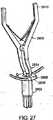
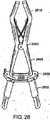
本発明の開創器が手術部位に対して所望の位置に配置されたら、手術部位を形成するために拡張可能なフレームを所望の位置まで移動させる。オプションとして、1または複数の伸延器具を用いて、拡張可能なフレームを移動させ、手術部位から組織を開創する。図26は、伸延器具の一実施形態を例示している。伸延器具2500は、取付け部分2502およびグリップ部分2504を有する。グリップ部分2504に力を加えて閉じると、取付け部分2502が広がるまたは拡張する。取付け部分2502を開創器に連結することで、グリップ部分に力を加えて拡張可能なフレームを所望の位置に移動させることができる。一部の実施形態では、取付け部分は、開創器の外径に取り付けられ、別の実施形態では、取付け部分は開創器の内径に取り付けられる(図27および図28に例示されている)。 Once the retractor of the present invention is in the desired position relative to the surgical site, the expandable frame is moved to the desired location to form the surgical site. Optionally, one or more distraction instruments are used to move the expandable frame and retract tissue from the surgical site. FIG. 26 illustrates one embodiment of a distraction device. The
一部の実施形態では、1または複数のラチェットアーム上の歯に係合して1または複数のベース要素をラチェットアームに対して移動させる1または複数のキーまたはねじを用いて、拡張可能なフレームを拡張または収縮させる。これにより、自由な調節、すなわち各ラチェットアームを所望の位置または所望の程度まで拡張させることが可能となる。 In some embodiments, an expandable frame using one or more keys or screws that engage teeth on one or more ratchet arms to move one or more base elements relative to the ratchet arms. Expand or contract. This allows free adjustment, i.e. each ratchet arm can be expanded to a desired position or to a desired degree.
図27は、開創器2602に対する伸延器具2600の取付けを例示している。取付け部分2604は、拡張可能なフレーム2608のアクセス口2606の内径に取り付けられる。図28に例示されているように、グリップ部分2610を互いに近づけて取付け部分2604を広げ、これにより拡張可能なフレーム2608を所望の位置に移動させることができる。 FIG. 27 illustrates attachment of the
一部の実施形態では、本発明は、生物に手術部位を形成するための方法を含む。一実施形態では、この方法は、生物に切開部を作り出すステップと、本発明の開創器を用いて切開部で生物の組織を開創し、ブレードの先端部によって少なくとも部分的に画定される手術部位を形成するステップを含む。一部の実施形態では、生物は哺乳動物である。別の実施形態では、哺乳動物はヒトである。 In some embodiments, the present invention includes a method for creating a surgical site in an organism. In one embodiment, the method includes the steps of creating an incision in a living organism and a surgical site that is at least partially defined by the tip of the blade using the retractor of the present invention to open the living tissue at the incision. Forming a step. In some embodiments, the organism is a mammal. In another embodiment, the mammal is a human.
一部の実施形態では、手術部位は、脊柱に近接して形成する。別の実施形態では、手術部位は、経椎間孔腰椎椎体間固定術(transforaminal lumbar interbody fusion procedure)、後方進入腰椎椎体間固定術、および後側方固定術からなる群の少なくとも1つを含む外科手術の際に形成される。 In some embodiments, the surgical site is formed proximate to the spinal column. In another embodiment, the surgical site is at least one of the group consisting of a transforaminal lumbar interbody fusion procedure, a posterior approach lumbar interbody fusion, and a posterior lateral fusion. Formed during surgery.
一部の実施形態では、切開部は、回想記を挿入する前に少なくとも1つのオブチュレータでまず拡張される。別の実施形態では、形成する手術部位の深さまで開創器を挿入する際に、開創器をオブチュレータの上に配置する。 In some embodiments, the incision is first expanded with at least one obturator prior to inserting the memoir. In another embodiment, the retractor is placed over the obturator as the retractor is inserted to the depth of the surgical site to be formed.
オプションとして、開創器は、所望の位置に開創器を固定する外科用開創器配置機構に取り付ける。配置機構の一例として、手術台に取り付ける調節可能な硬質アームを挙げることができる。 Optionally, the retractor is attached to a surgical retractor placement mechanism that secures the retractor in the desired position. An example of a placement mechanism is an adjustable hard arm that attaches to an operating table.
一部の実施形態では、本発明は、少なくとも1つのオブチュレータに取り付けられる外科用開創器を含む組立体を含む。例えば、本発明は、オブチュレータに機械的に取り付けられた外科用開創器を含む。オプションとして、外科用開創器は、オブチュレータに機械的に固定または固着しないで、オブチュレータ上に配置またはスライドさせる。 In some embodiments, the invention includes an assembly that includes a surgical retractor attached to at least one obturator. For example, the present invention includes a surgical retractor mechanically attached to an obturator. Optionally, the surgical retractor is placed or slid over the obturator without being mechanically secured or secured to the obturator.
別の実施形態では、本発明は、拡張可能なフレームおよび少なくとも2つの開創器ブレードを含む外科用開創器を含む。この拡張可能なフレームは、少なくとも2つのベース要素、およびこれらのベース要素を連結する少なくとも1つのコネクタを含み、少なくとも1つのベース要素がコネクタに沿って移動可能である。少なくとも2つの開創器ブレードは、拡張可能なフレームに取り付けられており、各開創器ブレードは、拡張可能なフレームに取り付けられた基端部、その基端部の反対側の先端部、および主軸を有する。少なくとも1つのベース要素に対してコネクタが移動すると、拡張可能なフレームは、第1の位置から第2の位置に移動し、これにより2つのベース要素間の平均距離が第1の距離まで増大し、2つの開創器ブレードの先端部間の平均距離が第2の距離まで増大する。この第1の距離は第2の距離よりも短い。 In another embodiment, the present invention includes a surgical retractor that includes an expandable frame and at least two retractor blades. The expandable frame includes at least two base elements and at least one connector connecting the base elements, the at least one base element being movable along the connector. At least two retractor blades are attached to the expandable frame, each retractor blade having a proximal end attached to the expandable frame, a distal end opposite the proximal end, and a main shaft. Have. As the connector moves relative to the at least one base element, the expandable frame moves from the first position to the second position, thereby increasing the average distance between the two base elements to the first distance. The average distance between the tips of the two retractor blades increases to a second distance. This first distance is shorter than the second distance.
別の実施形態では、本発明は、拡張可能なフレームおよび少なくとも2つの開創器ブレードを含む外科用開創器を含む。この拡張可能なフレームは、少なくとも2つのベース要素、およびこれらのベース要素を連結する少なくとも1つのコネクタを含み、少なくとも1つのベース要素がコネクタに沿って移動可能である。少なくとも2つの開創器ブレードは、拡張可能なフレームに取り付けられており、各ブレードは、拡張可能なフレームに取り付けられた基端部、この基端部とは反対側の先端部、主軸、および外面を有する。コネクタが少なくとも1つのベース要素に対して移動すると、拡張可能なフレームが第1の位置から第2の位置に移動し、これにより2つのベース要素間の平均距離が増大する。開創器ブレードの組み合わせられた外面は、拡張可能なフレームが第1の位置にあるときは円筒状である。 In another embodiment, the present invention includes a surgical retractor that includes an expandable frame and at least two retractor blades. The expandable frame includes at least two base elements and at least one connector connecting the base elements, the at least one base element being movable along the connector. At least two retractor blades are attached to the expandable frame, each blade having a proximal end attached to the expandable frame, a distal end opposite the proximal end, a main shaft, and an outer surface Have As the connector moves relative to the at least one base element, the expandable frame moves from the first position to the second position, thereby increasing the average distance between the two base elements. The combined outer surface of the retractor blade is cylindrical when the expandable frame is in the first position.
別の実施形態では、本発明は、ハウジング要素、ブレード部分、および円筒状拡張要素を含む外科用開創器を含む。このハウジング要素は、中心軸と、この中心軸に垂直な内径を有する導管を画定する円筒状部分を含む。ブレード部分は、円筒状部分の一端に隣接しており、少なくとも2つのブレードを含み、各ブレードの先端部分は、中心軸に対して移動可能である。円筒状拡張要素は、円筒状部分の内径よりも小さい外径を有し、ハウジング要素に移動可能に取り付けられている。第1の位置では、ブレード部分の先端部は、近接しており、ブレードの先端部分が中心軸に対して移動すると、ブレードが第1の位置から第2の位置に移動して、中心軸の全長に亘る連続的な導管が形成される。オプションとして、少なくとも1つのブレードはトウアウト突出部を含む。 In another embodiment, the present invention includes a surgical retractor that includes a housing element, a blade portion, and a cylindrical expansion element. The housing element includes a cylindrical portion that defines a central axis and a conduit having an inner diameter perpendicular to the central axis. The blade portion is adjacent to one end of the cylindrical portion and includes at least two blades, the tip portion of each blade being movable relative to the central axis. The cylindrical expansion element has an outer diameter that is smaller than the inner diameter of the cylindrical portion and is movably attached to the housing element. In the first position, the tip of the blade portion is close, and when the tip of the blade moves relative to the central axis, the blade moves from the first position to the second position, A continuous conduit over the entire length is formed. Optionally, the at least one blade includes a toe out protrusion.
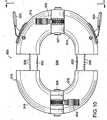
図29および図30は、本発明の開創器の一実施形態を例示している。図29は、第1の位置にある開創器2800を例示している。開創器2800は、中心軸2804を有するハウジング要素2802を含む。ハウジング要素2802は、中心軸2804に対して垂直な内径2808を有する導管を画定する円筒状部分2806を含む。ブレード部分2810は、円筒状部分2806の一端に隣接し、ブレード2812を含む。ブレード2812は、中心軸2804に対して移動可能な先端部分2814を有する。円筒状拡張要素2816は、ねじ山2818によってハウジング要素2802に移動可能に取り付けられている。円筒状拡張要素2816は、円筒状部分2806の内壁に延在する延長部2820を含むブレード拡張機構を含む。 29 and 30 illustrate one embodiment of the retractor of the present invention. FIG. 29 illustrates the
図29は、先端部2814が互いに近接している第1の位置にある開創器2800を例示している。図30は、拡張要素2816がハウジング要素2802に対して回動した後の開創器2800を例示している。このような回動により、拡張要素2816がねじ山2818に沿って押圧されて、延長部2820がブレード部分2810の内壁に押され、これによりブレード部分2812が中心軸2804から径方向に移動して、手術部位が拡張される。 FIG. 29 illustrates the
図29に例示されている第1の位置では、先端部2814は互いに近接して、ブレード部分2810が円錐を形成している。図30に例示されている第2の位置では、先端部2814が互いに対して広がり、互いに、かつ中心軸2804から離間している。第1の位置では、ブレード部分2810の円錐形状により、周囲組織に対して最小の外傷で開創器2800を生物内に容易に挿入(例えば、切開部を介して)することができる。所望の位置に達したら、開創器2800を第2の位置まで拡張し、これにより手術部位が形成され、実施者がその手術部位にアクセスすることができる。 In the first position illustrated in FIG. 29, the
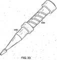
図31は、先端部3002が第1の位置にある開創器3000を例示している。図32は、先端部3002が第2の位置にある開創器3000を例示している。図33は、拡張要素3004が取り付けられた開創器3000を例示している。 FIG. 31 illustrates the
別の実施形態では、本発明は、生物に外科手術を行う方法を含む。この方法は、生物に切開部を作り出すステップと、開創器を用いて切開部周囲の組織を開創して手術部位を形成するステップと、その手術部位で外科手術を行うステップを含む。 In another embodiment, the present invention includes a method of performing a surgical operation on an organism. The method includes creating an incision in a living organism, using a retractor to open tissue around the incision to form a surgical site, and performing a surgical operation at the surgical site.
一部の実施形態では、本発明は、照明外科用カニューレを含む。一実施形態では、照明外科用カニューレは、外科用カニューレおよびインターフェイスリングを含む。この外科用カニューレは、外径、内径、先端部、および基端部を備え、この内径、先端部、および基端部は、内部領域を画定している。インターフェイスリングは、外科用カニューレの基端部に取り付けられ、光ファイバーワイヤのアレイと光子通信する光源インターフェイス機構を含む。このアレイは、カニューレの先端部に向かって光を案内するように構成されている。内部領域は、光源によって照明される。一部の実施形態では、インターフェイスリングは、光源(例えば、LEDランプ、または別の光源)を含む。 In some embodiments, the present invention includes an illuminated surgical cannula. In one embodiment, the illuminated surgical cannula includes a surgical cannula and an interface ring. The surgical cannula includes an outer diameter, an inner diameter, a distal end, and a proximal end, the inner diameter, the distal end, and the proximal end defining an interior region. The interface ring is attached to the proximal end of the surgical cannula and includes a light source interface mechanism that is in photon communication with an array of fiber optic wires. The array is configured to guide light toward the tip of the cannula. The inner area is illuminated by a light source. In some embodiments, the interface ring includes a light source (eg, an LED lamp or another light source).
一部の実施形態では、カニューレは、基端部でインターフェイスリングのアレイと光子通信し、かつ先端部に向かってカニューレの全長の少なくとも一部に沿って延在する少なくとも1本の光ファイバーワイヤを含む。別の実施形態では、光ファイバーワイヤの少なくとも一部が、外径と内径との間のカニューレ内に埋め込まれている。 In some embodiments, the cannula includes at least one fiber optic wire in photon communication with the array of interface rings at the proximal end and extending along at least a portion of the entire length of the cannula toward the distal end. . In another embodiment, at least a portion of the fiber optic wire is embedded in a cannula between the outer diameter and the inner diameter.
オプションとして、カニューレの少なくとも一部が半透明である。一部の実施形態では、カニューレの少なくとも一部は透明である。さらに別の実施形態では、カニューレチューブは、照明を補助するために光をとらえて所望の位置に光を向け直す構造(例えば、ベベルまたは表面の凹凸)を含む。 Optionally, at least a portion of the cannula is translucent. In some embodiments, at least a portion of the cannula is transparent. In yet another embodiment, the cannula tube includes a structure (eg, bevel or surface irregularities) that captures light and redirects it to a desired location to assist in illumination.
図34は、インターフェイスリングの一実施形態を例示している。インターフェイスリング3300は、光源インターフェイス機構3302を含む。光源インターフェイス機構3302は、外部光源(例えば、外科手術で一般に使用される光源)からの光を光ファイバーワイヤ3306のアレイ3304に案内する。インターフェイスリング3300は、実施者が取り付けられたカニューレにアクセスできるアクセス口3308を画定している。アレイ3304は、インターフェイスリング3300の周りに配置され、カニューレの全長に沿って光を投射する。オプションとして、アレイ3304は、光誘導材料の少なくとも一部を含むカニューレに光を案内する。一部の実施形態では、インターフェイスリングは、完全な円を形成し、本発明のカニューレまたは開創器の上部に一致する。他の実施形態では、インターフェイスリングは、円の一部(例えば、半円または4分の1円)を形成し、本発明のカニューレまたは開創器の上部に一致する。 FIG. 34 illustrates one embodiment of an interface ring. The
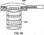
図35は、光誘導材料を含むカニューレの一部を例示している。カニューレ3400は、複数の光ファイバーワイヤ3402を含む。光ファイバーワイヤ3402は、カニューレ3400の壁部を形成する材料内に埋め込まれている。図36は、カニューレ3400の一部に取り付けられたインターフェイスリング3300を例示している。 FIG. 35 illustrates a portion of a cannula that includes a light guide material.
図面に例示されているカニューレは、本発明のカニューレの単なる一実施形態である。照明カニューレまたはその一部(例えば、インターフェイスリング)は、本発明のあらゆる開創器に用いることができる。 The cannula illustrated in the drawings is just one embodiment of the cannula of the present invention. An illumination cannula or part thereof (eg, an interface ring) can be used with any retractor of the present invention.
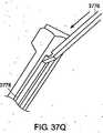
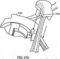
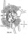
一部の実施形態では、本発明は、本発明の開創器を用いてヒトの脊椎に対して外科手術を行う方法を含む。図37A‐図37Uは、ヒトの脊椎に対して外科手術を行う際に開創器(例えば、本発明の開創器)を用いる方法、および関連した本発明の器具および道具を含む本発明の実施形態を例示している。 In some embodiments, the present invention includes a method of performing surgery on a human spine using the retractor of the present invention. 37A-37U are embodiments of the present invention that include a method of using a retractor (e.g., a retractor of the present invention) in performing a surgical operation on a human spine, and associated instruments and tools of the present invention. Is illustrated.
図37Aは、イメージングが妨げられないように台3704(例えば、ジャクソン台(Jackson Table)または画像処理に用いられる他の台)上の腹臥位の患者3702を例示している。一部の実施形態では、フレーム(例えば、ウィルソンフレーム(Wilson frame))を用いて、実施者が患者3702を所望の位置に配置しやすいようにする。加えて、患者の中間腿または上腿の側方に位置する台のレール上にソケット(例えば、クラークソケット(Clark Socket))を配置して、硬質アーム組立体の配置を容易にすることができる。 FIG. 37A illustrates a
手術部位の位置を適切に定めることにより、外科手術が容易になり、切開部を拡張する必要性が最小になる。一部の実施形態では、脊椎に平行に延在する多裂筋および最長筋を拡張する。オプションとして、蛍光透視を用いて所望のレベルの位置を求め、蛍光透視映像の中心に標的手術部位を維持するように十分に注意する。例えば、経椎間孔腰椎椎体固定術(transforminal lumbar interbody fusion procedure)の場合、標的の中心は、通常は、所望の円板レベルの椎間関節の内側縁である。切開部テンプレートを用いて(蛍光透視を用いても用いなくてもよい)、手術する適切なレベルの円板空間に切開部の中心を位置合わせすることができる。患者3702の皮膚内に開創器を押圧すると圧痕ができ、必要な切開部の大きさの良好な印となる。 Proper positioning of the surgical site facilitates surgery and minimizes the need to expand the incision. In some embodiments, the multifidus and longest muscles that extend parallel to the spine are expanded. As an option, fluoroscopy is used to determine the desired level of position and sufficient care is taken to maintain the target surgical site in the center of the fluoroscopic image. For example, in the case of a transformal lumbar interbody fusion procedure, the center of the target is usually the medial edge of the desired disc level of the facet joint. The incision template can be used (with or without fluoroscopy) to align the center of the incision with the appropriate level of disc space to be operated on. When the retractor is pressed into the skin of the
手術部位の位置を定めたら、本発明の開創器(例えば、半分または完全に収縮または閉じた状態の本発明の開創器)よりもわずかに大きい縦の切開部を作る。一部の実施形態では、拡張器を筋膜に刺入してその筋膜を拡張できるため、皮膚のみを切開する。 Once the surgical site is located, a longitudinal incision is made that is slightly larger than the retractor of the present invention (eg, the retractor of the present invention half or fully contracted or closed). In some embodiments, only the skin is incised because a dilator can be inserted into the fascia to expand the fascia.
切開部が形成されたら、図37Bに例示されているように、拡張器を切開部内に挿入し、筋膜に鈍的に刺入し、層状レベルに至る傍脊柱筋組織を拡張する。オプションとして、第1の拡張器を挿入する前に筋膜を切開する。拡張器の位置は、蛍光透視で確認することができる。触感に注意しながら、線3716に沿って緩やかに杖を振る動きで、棘突起の基部であって椎間関節の上に位置する層から傍脊柱筋を除去して、これにより観察を容易にし、拡張器および開創器を小関節面に完全に配置できるようにする。 Once the incision is formed, as shown in FIG. 37B, a dilator is inserted into the incision and bluntly inserted into the fascia to dilate the paraspinal muscle tissue to the layered level. Optionally, an incision is made in the fascia before inserting the first dilator. The position of the dilator can be confirmed by fluoroscopy. Taking care of the tactile sensation, gently swinging the cane along
図37Cに示されているように、拡張器3706の上に次に大きい拡張器3710を配置して手術部位3708まで案内して連続的な拡張を行うことができる。次いで、同様に拡張器3710の上に拡張器3712を配置し、次いで、拡張器3712の上に拡張器3714を配置する。一部の実施形態では、導入器を用いて大きな拡張器を挿入する。 As shown in FIG. 37C, the next
一部の実施形態では、皮膚が拡張器に接触する位置から深さを測定する。この深さは、拡張器3710または3712が骨と同一面であって最も正確に測定できるため、これらの拡張器を用いて最も効率的に測定することができる。 In some embodiments, the depth is measured from the location where the skin contacts the dilator. This depth can be measured most efficiently with these dilators because
切開部が拡張されたら、本発明の開創器を手術部位3708に案内する。一部の実施形態では、開創器を、開放ウィルツ法(open Wiltse approach)で手術部位3708に案内する。この方法では、天然の筋平面の位置を、固定された正中線切開部または側方切開部を介して確認する。 Once the incision is expanded, the retractor of the present invention is guided to the
開創器は、手術部位3708に案内する前に組み立てる。図37Dは、組み立てられた開創器3730を例示している。開創器3732は、ベース要素3734、3736、3738、および3740を含む。 The retractor is assembled prior to being guided to the
図37Eは、組立て工程の1つのステップを例示している。ベース要素3740はアーム3742を含む。ベース要素3734は、アーム3744を含み、アーム孔3750を画定している。解除ボタン3752を押してベース要素3734のロック機構を解除し、アーム3742をアーム孔3750から案内し、これによりベース要素3740をベース要素3734に連結すなわち組み付ける。同様に、ベース要素3736をベース要素3738に組み付ける。 FIG. 37E illustrates one step of the assembly process.
ベース要素3740がベース要素3734に組み付けられ、ベース要素3438がベース要素3736に組み付けられたら、解除ボタン3754および3756を押圧し、アーム3748をベース要素3740内に案内し、アーム3744をベース要素3740内に案内し、これにより、図37Fに示されているように4つ全てのベース要素を組み立てる。次いで、開創器ブレード延長部3760、3762、3764、および3766をそれぞれ、図37Gに例示されているように、ベース要素3734、3736、3738、および3740内にスライドさせる。このようにして、本発明の実施者が、図37Dに示されているように開創器3730を組み立てる。 Once the
オプションとして、開創器3730の伸縮ブレード延長部を、開創器を患者3702の体内に挿入する前に所望の長さまで延出させる。図37Eは、本発明の実施者がブレード延長部を容易に延出できるように用いられるブレード深さタワー3760を例示している。タワー3760は、シャフト3766に組み付けられるリング3762を含む。シャフト3766は、その上に2つの連続したマーク(それぞれが異なった大きさの開創器に対応する)を有する。リング3762を回動させて、リング3762をシャフト3766の全長に亘って上方または下方に移動させる。 Optionally, the telescopic blade extension of the
タワー3760を用いてブレードを延出させるには、本発明の実施者が、シャフト3766に沿った位置までリング3762を回動させる。シャフト3766上のマークを用いて所望の位置を決定する。図37Iに示されているように、開創器3730を、シャフト3766の上端部3764の上からリング3730の下側に案内する。上端部3764は、開創器3730のブレード延長部に係合して、開創器3730がリング3762の下側に案内される時にこれらの延長部を延出させる。 To extend the blade using the
本発明の一部の実施形態では、患者に挿入する前に開創器を挿入器に取り付ける。図37Jは、ハンドル挿入器3768に取り付けられた開創器3730を例示している。ハンドル挿入器3768は、開創器3730のフレーム上の取付け孔内に挿入器3768の取付けピンを挿入して開創器3730に取り付ける。挿入器3768に取り付けたら、本発明の実施者が、挿入器3768を用いて開創器3730を拡張器上に配置して手術部位3708まで送る。挿入の際には、拡張器の下側の軟組織のクリープを防止するべく拡張器が小関節面上に完全に維持されるように注意を払うべきである。 In some embodiments of the invention, the retractor is attached to the inserter prior to insertion into the patient. FIG. 37J illustrates the
患者3702の体内に挿入したら、図37Lに例示されているように、1または複数の硬質アーム3770を開創器3730に取付けまたは固定することができる。硬質アーム3770は、手術台に固定し、拡張可能なフレーム上の取付け孔の1つで開創器3730に取り付ける。硬質アーム3770は、外科手術の際に調整することができるため、本発明の実施者が開創器3730を所望の位置に案内することができる。 Once inserted into the
図37Mに例示されているように、拡張器3706、3710、3712、および3714が患者3702から除去される。拡張器の除去の際は、軟組織のクリープを防止するべく薄層および小関節面に対して開創器3730が完全に維持されるように注意を払うべきである。
本発明の一部の実施形態では、電気メスを用いて、挿入された開創器の内側の骨に付着して残っている全ての筋肉を除去して、組織からの出血を防止または軽減する。この骨を、作動していない延出したボビーチップ(bovie tip)で軽く触診して、このボビーチップが骨に接触していることを確認することができる。脳下垂体骨鉗子を用いて、露出部から断片を引き抜くことができる。このような操作の際に十分に観察できるように、オプションとして潅流を行うことができる。 In some embodiments of the invention, an electric scalpel is used to remove any remaining muscle that remains attached to the bone inside the inserted retractor to prevent or reduce bleeding from the tissue. The bone can be lightly palpated with a non-actuated extended bovie tip to confirm that the bobby tip is in contact with the bone. The pituitary bone forceps can be used to pull out the fragment from the exposed part. Perfusion can optionally be performed so that it can be fully observed during such operations.
開創器3732が挿入され、拡張器が除去されたら、開創器3732を、図37Nに例示されているように、伸延器具3772を用いて拡張することができる。開創器3732は、器具3772を開創器3732の上部内に挿入し、この器具3772のハンドルを所望の程度に閉じて、頭尾方向および/または内側‐外側方向に拡張することができる。拡張可能なフレームのロック機構の歯により、微調整が可能となり、開創器3732を拡張した位置に保持することができる。本発明の一部の実施形態では、伸延器具を湾曲したラックに平行にして用いて、開創器に対する過度の応力を防止している。 Once the retractor 3732 is inserted and the dilator is removed, the retractor 3732 can be expanded using a
開創器3730を拡張して椎間関節が見えるようになったら、ブレードプッシャー3774を用いて、例えば作業空間における軟組織のクリープをさらに防止するために伸縮ブレード延長部を配置することができる。図37Oは、本発明の実施者がプッシャー3774で延長部を配置しているのを例示している。 Once the
オプションとして、この延長部を外科手術の任意の時点で取り外し、かつ/または上方に調節することができる。図37P‐図37Rは、本発明の実施者がブレード延長部をブレードリムーバー3776を用いて上方に除去または調節するのを例示している。図37Qおよび図37Rは、ブレード延長部3778に係合しているリムーバー3776の拡大図を例示している。ブレードリムーバー3776を伸縮ブレード延長部3778の歯の内部に挿入し、図37Rに例示されているように、リムーバー3776のハンドルを延長部3778のロック機構を外すため外側に移動させる。これにより、図37Pに例示されているように、延長部3778を上方に取り外し、かつ/または調節することができる。 Optionally, the extension can be removed and / or adjusted upward at any point in the surgical procedure. FIGS. 37P-37R illustrate the practitioner of the present invention removing or adjusting the blade extension upward using a
所望に応じて、追加ブレードおよび/または外科器具を開創器3730に取り付けることができる。図37S‐図37Uは、このような取付けを例示している。図37Sは、開創器3730のベース要素の取付け点を含む開創器3730の所定の部分に対する内側‐外側ブレード3780の取付けを例示している。図37Tは、ブレード3780が開創器3730に取り付けられた後の開創器3730の上面図を例示している。ブレード3780は、取付け点に固定され、アームの一部分によって支持されている。図37Uは、開創器3730に取り付けられた光源3782を例示している。所望に応じて、光源3782は、開創器3730の拡張の度合いによって内側または外側に調節する。 Additional blades and / or surgical instruments can be attached to the
一部の実施形態では、本発明は外科手術方法を含む。この方法は、哺乳動物の組織を切開して切開部を作り出すステップと、この切開部を拡張してこの切開部から手術部位に至る経路を作り出すステップと、開創器(例えば、本発明の開創器)をこの経路内に案内するステップと、作業通路を作り出すステップと、この作業通路を介して外科手術の少なくとも一部を行うステップを含む。この作業通路は、例えば、開創器を拡張して作り出すことができる。この開創器の拡張は、第1の開創器ブレードおよび第2の開創器ブレードの少なくとも一方を開創器の第1のコネクタに沿って移動させて第1の開創器ブレードを第2の開創器ブレードから分離し、第3の開創器ブレードおよび第4の開創器ブレードの少なくとも一方を第2のコネクタに沿って移動させて第3の開創器ブレードを第4の開創器ブレードから分離して行う。第2のコネクタは、第1のコネクタに対して所定の角度をなして配置されている。 In some embodiments, the present invention includes a surgical method. The method includes incising mammalian tissue to create an incision, expanding the incision to create a path from the incision to the surgical site, and a retractor (eg, the retractor of the present invention). ) Into the path, creating a working path, and performing at least a portion of the surgery through the working path. This working channel can be created, for example, by expanding the retractor. The retractor extension includes moving at least one of the first retractor blade and the second retractor blade along the first connector of the retractor to move the first retractor blade to the second retractor blade. Separating the third retractor blade from the fourth retractor blade by moving at least one of the third retractor blade and the fourth retractor blade along the second connector. The second connector is disposed at a predetermined angle with respect to the first connector.
一部の実施形態では、本発明は、脊椎へのアクセスする方法を提供する。一実施形態では、この方法は、哺乳動物の組織を切開して切開部を作り出すステップと、この切開部を拡張してこの切開部から手術部位に至る経路を作り出すステップと、開創器(例えば、本発明の開創器)をこの経路内に案内するステップと、少なくとも2つの開創器ブレードを分離して開創器が挿入する作業通路を作り出すステップと、この作業通路を介して第1の椎骨で外科手術の少なくとも一部を行うステップと、2つの開創器ブレード間に器具またはインプラントを案内して第2の椎骨に近接した組織を移動させて、第1の椎骨に近接した第2の椎骨を露出させるステップと、作業通路を介して第2の椎骨で外科手術の少なくとも一部を行うステップを含む。第2の椎骨に近接した組織は、2つの開創器ブレード間に器具またはインプラントを案内し、この組織を切除するかまたは第2の椎骨の近傍から離れるようにして、移動させることができる。こうすることにより、哺乳動物の皮膚の切開部を拡張し、かつ/または哺乳動物の皮膚に第2の切開部を作り出すことなく、実施者が2つの椎骨にアクセスすることができる。 In some embodiments, the present invention provides a method of accessing the spine. In one embodiment, the method includes incising mammalian tissue to create an incision, expanding the incision to create a path from the incision to the surgical site, and a retractor (e.g., Guiding the retractor of the present invention into the path, separating the at least two retractor blades to create a working channel for insertion by the retractor, and surgically operating on the first vertebra through the working channel. Performing at least a portion of the surgery and guiding a tool or implant between the two retractor blades to move tissue adjacent to the second vertebra to expose the second vertebra adjacent to the first vertebra And performing at least a portion of the surgery on the second vertebra through the working channel. Tissue adjacent to the second vertebra can be moved by guiding the instrument or implant between the two retractor blades and excising or leaving the vicinity of the second vertebra. This allows the practitioner to access the two vertebrae without expanding the mammalian skin incision and / or creating a second incision in the mammalian skin.
一部の実施形態では、第1の開創器ブレード、第2の開創器ブレード、第3の開創器ブレード、および/または第4の開創器ブレードを非線形の線(例えば、弧状の線)に沿って移動させる。別の実施形態では、ブレードは線形の線(すなわち、直線)に沿って移動させる。 In some embodiments, the first retractor blade, the second retractor blade, the third retractor blade, and / or the fourth retractor blade is along a non-linear line (eg, an arcuate line). To move. In another embodiment, the blade is moved along a linear line (ie, a straight line).
一部の実施形態では、本発明はキットを含む。このキットは、外科用開創器、この開創器のフレームに取り付けることができる開創器挿入器、ブレード深さタワー、伸延器、および少なくとも1つのブレード調節器具(例えば、ブレードリムーバー器具やブレードプッシャー器具などの上記した器具の1つ)を含む。別の実施形態では、キットは、少なくとも1つのオブチュレータおよび少なくとも2つの拡張器(例えば、異なる直径の2つ以上の拡張器)を含む。さらに別の実施形態では、キットは、取付け装置の少なくとも一部(例えば、硬質アームの一部)を含む。 In some embodiments, the invention includes a kit. The kit includes a surgical retractor, a retractor inserter that can be attached to the retractor frame, a blade depth tower, a distractor, and at least one blade adjustment instrument (eg, a blade remover instrument, a blade pusher instrument, etc.) One of the above-mentioned appliances). In another embodiment, the kit includes at least one obturator and at least two dilators (eg, two or more dilators of different diameters). In yet another embodiment, the kit includes at least a portion of an attachment device (eg, a portion of a rigid arm).
〔実施の態様〕
(1)外科用開創器において、
フレームであって、
第1のベース要素と、
第2のベース要素と、
前記第1のベース要素と前記第2のベース要素を連結するコネクタと、を備え、前記第1のベース要素および前記第2のベース要素との少なくとも一方が、前記コネクタの長さに沿って移動可能であり、前記コネクタが前記第1のベース要素または前記第2のベース要素に対して移動すると、前記フレームが第1の位置から第2の位置に移動して、前記第1のベース要素と前記第2のベース要素との間の距離が変化する、前記フレームと、
前記フレームに取り付けられた少なくとも2つの開創器ブレードと、
を含む、外科用開創器。
(2)実施態様(1)に記載の外科用開創器において、
少なくとも1つのブレードが、クリップで前記フレームに取り付けられている、外科用開創器。
(3)実施態様(1)に記載の外科用開創器において、
少なくとも1つのブレードおよびベース要素が、1つの連続した材料部分から形成されている、外科用開創器。
(4)実施態様(1)に記載の外科用開創器において、
前記ブレードの1つに伸縮自在およびスライド可能に取り付けられているブレード延長部をさらに含む、外科用開創器。
(5)実施態様(1)に記載の外科用開創器において、
少なくとも2つのブレードの位置を互いに対して固定するロック機構をさらに含む、外科用開創器。Embodiment
(1) In surgical retractors,
A frame,
A first base element;
A second base element;
A connector connecting the first base element and the second base element, wherein at least one of the first base element and the second base element moves along a length of the connector And when the connector moves relative to the first base element or the second base element, the frame moves from a first position to a second position, and the first base element and The frame in which the distance between the second base element varies;
At least two retractor blades attached to the frame;
Surgical retractor, including
(2) In the surgical retractor according to the embodiment (1),
A surgical retractor, wherein at least one blade is attached to the frame with a clip.
(3) In the surgical retractor according to the embodiment (1),
Surgical retractor, wherein at least one blade and base element are formed from one continuous piece of material.
(4) In the surgical retractor according to embodiment (1),
The surgical retractor further comprising a blade extension that is telescopically and slidably attached to one of the blades.
(5) In the surgical retractor according to the embodiment (1),
The surgical retractor further comprising a locking mechanism that secures the position of the at least two blades relative to each other.
(6)実施態様(1)に記載の外科用開創器において、
第2のコネクタと、
前記コネクタに取り付けられた第3のベース要素と、
前記コネクタに取り付けられた第4のベース要素と、をさらに含み、前記第3のベース要素および前記第4のベース要素の少なくとも一方が、前記コネクタの長さに沿って移動可能であって、この移動により、前記第3のベース要素と前記第4のベース要素との間の距離が変化するようになっており、前記第1のベース要素および前記第2のベース要素が前記第3のベース要素および前記第4のベース要素に対して移動可能である、外科用開創器。
(7)実施態様(1)に記載の外科用開創器において、
前記拡張可能なフレームが、外科用器具または開創器ブレードを支持するための少なくとも1つの取付け点をさらに含む、外科用開創器。
(8)実施態様(1)に記載の外科用開創器において、
前記第1のコネクタが弧状である、外科用開創器。
(9)実施態様(1)に記載の外科用開創器において、
前記第1のコネクタが直線状である、外科用開創器。
(10)実施態様(1)に記載の外科用開創器において、
前記フレームが前記第1の位置にあるときに、前記ブレードが導管を画定する、外科用開創器。(6) In the surgical retractor according to the embodiment (1),
A second connector;
A third base element attached to the connector;
A fourth base element attached to the connector, wherein at least one of the third base element and the fourth base element is movable along the length of the connector, The movement changes a distance between the third base element and the fourth base element, and the first base element and the second base element are changed to the third base element. And a surgical retractor movable relative to the fourth base element.
(7) In the surgical retractor according to the embodiment (1),
The surgical retractor, wherein the expandable frame further includes at least one attachment point for supporting a surgical instrument or retractor blade.
(8) In the surgical retractor according to the embodiment (1),
The surgical retractor, wherein the first connector is arcuate.
(9) In the surgical retractor according to embodiment (1),
The surgical retractor, wherein the first connector is straight.
(10) In the surgical retractor according to the embodiment (1),
The surgical retractor wherein the blade defines a conduit when the frame is in the first position.
(11)実施態様(1)に記載の外科用開創器において、
前記フレームが第2の位置にあるときに、前記ベース要素がアクセス口を画定する、外科用開創器。
(12)実施態様(11)に記載の外科用開創器において、
前記各ブレードが、前記フレームに取り付けられた基端部、およびその基端部の反対側の先端部を備えており、前記アクセス口が、前記拡張可能なフレームが前記第2の位置にあるときに、任意の2つのブレードの先端部間の最大距離よりも小さい平均直径を有する、外科用開創器。
(13)実施態様(1)に記載の外科用開創器において、
前記ベース要素が、実質的に主平面にある前記コネクタに沿って移動可能である、外科用開創器。
(14)実施態様(1)に記載の外科用開創器において、
前記フレームが前記第1の位置にあるときに、前記ブレードが互いに接触する、外科用開創器。
(15)外科用開創器において、
第1の開創器ブレードおよび第2の開創器ブレードと、
前記第1の開創器ブレードの基端部および前記第2の開創器ブレードの基端部に取り付けられた第1のコネクタであって、前記第1の開創器ブレードまたは前記第2の開創器ブレードの少なくとも一方が、前記第1のコネクタの長さに平行な線に沿って移動可能である、第1のコネクタと、
第3の開創器ブレードおよび第4の開創器ブレードと、
前記第3の開創器ブレードの基端部および前記第4の開創器ブレードの基端部に取り付けられた第2のコネクタであって、前記第3の開創器ブレードまたは前記第4の開創器ブレードの少なくとも一方が、前記第2のコネクタの長さに平行な線に沿って移動可能であり、前記第1のコネクタまたは前記第2のコネクタの少なくとも一方が、前記第1のコネクタと前記第2のコネクタを横断する線に沿って移動可能である、第2のコネクタと、
を具備する、外科用開創器。(11) In the surgical retractor according to embodiment (1),
The surgical retractor, wherein the base element defines an access port when the frame is in the second position.
(12) In the surgical retractor according to embodiment (11),
Each of the blades includes a proximal end attached to the frame and a distal end opposite to the proximal end, and the access port has the expandable frame in the second position. A surgical retractor having an average diameter less than the maximum distance between the tips of any two blades.
(13) In the surgical retractor according to embodiment (1),
Surgical retractor, wherein the base element is movable along the connector in a substantially plane.
(14) In the surgical retractor according to embodiment (1),
A surgical retractor wherein the blades contact each other when the frame is in the first position.
(15) In surgical retractors,
A first retractor blade and a second retractor blade;
A first connector attached to a proximal end of the first retractor blade and a proximal end of the second retractor blade, the first retractor blade or the second retractor blade At least one of which is movable along a line parallel to the length of the first connector;
A third retractor blade and a fourth retractor blade;
A second connector attached to a proximal end of the third retractor blade and a proximal end of the fourth retractor blade, wherein the third retractor blade or the fourth retractor blade At least one of the first connector and the second connector is movable along a line parallel to a length of the second connector, and at least one of the first connector and the second connector is the first connector and the second connector. A second connector movable along a line traversing the connector;
Surgical retractor comprising:
(16)実施態様(15)に記載の外科用開創器において、
前記第1のコネクタまたは前記第2のコネクタが湾曲している、外科用開創器。
(17)実施態様(15)に記載の外科用開創器において、
前記第1の開創器ブレードまたは前記第2の開創器ブレードがベース要素に取り付けられており、このベース要素が前記第1のコネクタに取り付けられている、外科用開創器。
(18)実施態様(15)に記載の外科用開創器において、
前記開創器ブレードが、これらのブレードが全体として導管を画定する位置まで移動可能である、外科用開創器。
(19)オブチュレータに取り付けられた外科用開創器を含む組立体。
(20)外科用開創器において、
中心軸を有するハウジング要素であって、
前記中心軸に対して垂直な内径を有する導管を画定する円筒状部分と、
前記円筒状部分の一端に隣接したブレード部分であって、少なくとも2つのブレードを含み、これらの各ブレードの先端部分が、前記中心軸に対して移動可能であり、第1の位置では、前記ブレード部分の先端部が近接し、前記中心軸に対して前記ブレードの先端部が移動すると、前記ブレードが前記第1の位置から第2の位置に移動して前記中心軸の長さに沿った導管を形成する、前記ブレード部分と、を備えた前記ハウジング要素と、
外径を有する円筒状拡張要素であって、前記外径が、前記円筒状部分の内径よりも小さく、前記ハウジング要素に移動可能に取り付けられている、前記円筒状拡張要素と、
を具備する、外科用開創器。(16) In the surgical retractor according to embodiment (15),
A surgical retractor, wherein the first connector or the second connector is curved.
(17) In the surgical retractor according to embodiment (15),
A surgical retractor, wherein the first retractor blade or the second retractor blade is attached to a base element, and the base element is attached to the first connector.
(18) In the surgical retractor according to embodiment (15),
A surgical retractor wherein the retractor blades are movable to a position where the blades generally define a conduit.
(19) An assembly comprising a surgical retractor attached to an obturator.
(20) In a surgical retractor,
A housing element having a central axis,
A cylindrical portion defining a conduit having an inner diameter perpendicular to the central axis;
A blade portion adjacent to one end of the cylindrical portion, the blade portion including at least two blades, wherein a tip portion of each of the blades is movable with respect to the central axis, and in a first position, the blade When the tip of the part is close and the tip of the blade moves relative to the central axis, the blade moves from the first position to the second position and runs along the length of the central axis. Forming the blade portion, the housing element comprising:
A cylindrical expansion element having an outer diameter, wherein the outer diameter is smaller than the inner diameter of the cylindrical portion and is movably attached to the housing element;
Surgical retractor comprising:
(21)外科用照明カニューレにおいて、
外径、内径、先端部、および基端部を有する外科用カニューレであって、前記内径、前記先端部、および前記基端部によって内部領域が画定されている、前記外科用カニューレと、
前記基端部に取り付けられたインターフェイスリングであって、光ファイバーワイヤのアレイと光子通信する光源インターフェイスを含み、前記アレイが、光を前記カニューレの先端部に向かって案内するように配置されている、前記インターフェイスリングと、を含む、外科用照明カニューレ。
(22)外科手術方法において、
哺乳動物の組織を切開して切開部を作り出すステップと、
前記切開部を拡張して前記切開部から手術部位に至る経路を作り出すステップと、
開創器を前記経路内に導入するステップと、
前記開創器を拡張させて作業通路を作り出すステップであって、この開創器の拡張が、
第1の開創器ブレードおよび第2の開創器ブレードの少なくとも一方を前記開創器の第1のコネクタに沿って移動させて、前記第1の開創器ブレードを前記第2の開創器ブレードから分離させるステップと、
第3の開創器ブレードおよび第4の開創器ブレードの少なくとも一方を、前記第1のコネクタに対して所定の角度に配置されている第2のコネクタに沿って移動させて、前記第3の開創器ブレードを前記第4の開創器ブレードから分離するステップと、によって行われる、前記作業通路を作り出すステップと、
前記作業通路を介して外科手術の少なくとも一部を行うステップと、
を含む、外科手術方法。
(23)実施態様(22)に記載の外科手術方法において、
前記開創器が、第1のベース要素、第2のベース要素、およびコネクタを有するフレームを含み、
前記コネクタが、前記第1のベース要素と前記第2のベース要素を連結し、前記第1のベース要素および前記第2のベース要素の少なくとも一方が、前記コネクタの長さに沿って移動可能であり、前記コネクタが前記第1のベース要素または前記第2のベース要素に対して移動すると、前記フレームが、第1の位置から第2の位置に移動して、前記第1のベース要素と前記第2のベース要素との間の距離が変化する、方法。
(24)実施態様(22)に記載の外科手術方法において、
前記経路が第1の椎骨まで延びており、前記外科手術の少なくとも一部が、前記第1の椎骨で行われ、前記方法が、少なくとも2つの開創器ブレードの間に器具またはインプラントを案内して、前記第1の椎骨に近接した第2の椎骨にアクセスするステップをさらに含む、外科手術方法。
(25)実施態様(22)に記載の外科手術方法において、
前記開創器が前記経路内に導入される前に、前記開創器がオブチュレータに取り付けられる、外科手術方法。(21) In a surgical illumination cannula,
A surgical cannula having an outer diameter, an inner diameter, a distal end, and a proximal end, wherein the surgical cannula has an interior region defined by the inner diameter, the distal end, and the proximal end;
An interface ring attached to the proximal end including a light source interface in photon communication with an array of fiber optic wires, the array being arranged to guide light toward the distal end of the cannula; A surgical illumination cannula comprising the interface ring.
(22) In the surgical method,
Incising mammalian tissue to create an incision;
Expanding the incision to create a path from the incision to the surgical site;
Introducing a retractor into the path;
Expanding the retractor to create a working channel, the expansion of the retractor comprising:
Moving at least one of the first retractor blade and the second retractor blade along the first connector of the retractor to separate the first retractor blade from the second retractor blade Steps,
At least one of the third retractor blade and the fourth retractor blade is moved along a second connector disposed at a predetermined angle with respect to the first connector, so that the third retractor is moved. Separating a retractor blade from the fourth retractor blade, creating the working path,
Performing at least part of a surgical operation through the working channel;
Surgical methods including.
(23) In the surgical operation method according to the embodiment (22),
The retractor includes a frame having a first base element, a second base element, and a connector;
The connector connects the first base element and the second base element, and at least one of the first base element and the second base element is movable along the length of the connector. And when the connector moves relative to the first base element or the second base element, the frame moves from a first position to a second position, and the first base element and the The method wherein the distance between the second base element changes.
(24) In the surgical operation method according to embodiment (22),
The path extends to a first vertebra, at least a portion of the surgery is performed on the first vertebra, and the method guides an instrument or implant between at least two retractor blades. A surgical method further comprising accessing a second vertebra proximate to the first vertebra.
(25) In the surgical operation method according to the embodiment (22),
A surgical method wherein the retractor is attached to an obturator before the retractor is introduced into the path.
(26)実施態様(22)に記載の外科手術方法において、
前記第1の開創器ブレードおよび前記第2の開創器ブレードの少なくとも一方が非線形の線に沿って移動する、外科手術方法。
(27)実施態様(22)に記載の外科手術方法において、
前記第1の開創器ブレードおよび前記第2の開創器ブレードの少なくとも一方が線形の線に沿って移動する、外科手術方法。
(28)実施態様(22)に記載の外科手術方法において、
前記第3の開創器ブレードおよび前記第4の開創器ブレードの少なくとも一方が非線形の線に沿って移動する、外科手術方法。
(29)実施態様(22)に記載の外科手術方法において、
前記第3の開創器ブレードおよび前記第4の開創器ブレードの少なくとも一方が線形の線に沿って移動する、外科手術方法。
(30)椎骨へのアクセスする方法において、
哺乳動物の組織を切開して切開部を作り出すステップと、
前記切開部を拡張して前記切開部から手術部位に至る経路を作り出すステップと、
開創器を前記経路内に案内するステップと、
少なくとも2つの開創器ブレードを分離させて、前記開創器を通じて作業通路を作り出すステップと、
前記作業通路を介して第1の椎骨で外科手術の少なくとも一部を行うステップと、
器具またはインプラントを2つの前記開創器ブレード間に案内して第2の椎骨に近接した組織を移動させて、前記第1の椎骨に近接した前記第2の椎骨を露出させるステップと、
前記作業通路を介して前記第2の椎骨で外科手術の少なくとも一部を行うステップと、を含む、方法。(26) In the surgical operation method according to the embodiment (22),
A surgical method, wherein at least one of the first retractor blade and the second retractor blade moves along a non-linear line.
(27) In the surgical operation method according to the embodiment (22),
A surgical method, wherein at least one of the first retractor blade and the second retractor blade moves along a linear line.
(28) In the surgical operation method according to the embodiment (22),
A surgical method, wherein at least one of the third retractor blade and the fourth retractor blade moves along a non-linear line.
(29) In the surgical operation method according to embodiment (22),
A surgical method, wherein at least one of the third retractor blade and the fourth retractor blade moves along a linear line.
(30) In a method for accessing a vertebra,
Incising mammalian tissue to create an incision;
Expanding the incision to create a path from the incision to the surgical site;
Guiding a retractor into the path;
Separating at least two retractor blades to create a working channel through the retractor;
Performing at least a portion of a surgical operation on the first vertebra through the working channel;
Guiding a tool or implant between the two retractor blades to move tissue proximate to the second vertebra to expose the second vertebra proximate to the first vertebra;
Performing at least a portion of a surgical operation on the second vertebra through the working channel.
(31)実施態様(30)に記載の方法において、
前記開創器が前記経路内に導入される前に、前記開創器がオブチュレータに取り付けられる、方法。
(32)実施態様(30)に記載の方法において、
前記開創器が、第1のベース要素、第2のベース要素、およびコネクタを有するフレームを含み、
前記コネクタが、前記第1のベース要素と前記第2のベース要素を連結し、前記第1のベース要素および前記第2のベース要素の少なくとも一方が、前記コネクタの長さに沿って移動可能であり、前記コネクタが前記第1のベース要素または前記第2のベース要素に対して移動すると、前記フレームが、第1の位置から第2の位置に移動して、前記第1のベース要素と前記第2のベース要素との間の距離が変化する、方法。
(33)実施態様(32)に記載の方法において、
前記第1の開創器ブレードおよび前記第2の開創器ブレードの少なくとも一方が非線形の線に沿って移動する、方法。
(34)実施態様(32)に記載の方法において、
前記第1の開創器ブレードおよび前記第2の開創器ブレードの少なくとも一方が線形の線に沿って移動する、方法。
(35)実施態様(32)に記載の方法において、
前記第3の開創器ブレードおよび前記第4の開創器ブレードの少なくとも一方が非線形の線に沿って移動する、方法。(31) In the method according to embodiment (30),
The method wherein the retractor is attached to an obturator before the retractor is introduced into the path.
(32) In the method according to embodiment (30),
The retractor includes a frame having a first base element, a second base element, and a connector;
The connector connects the first base element and the second base element, and at least one of the first base element and the second base element is movable along the length of the connector. And when the connector moves relative to the first base element or the second base element, the frame moves from a first position to a second position, and the first base element and the The method wherein the distance between the second base element changes.
(33) In the method according to embodiment (32),
The method wherein at least one of the first retractor blade and the second retractor blade moves along a non-linear line.
(34) In the method according to embodiment (32),
The method wherein at least one of the first retractor blade and the second retractor blade moves along a linear line.
(35) In the method according to embodiment (32),
The method wherein at least one of the third retractor blade and the fourth retractor blade moves along a non-linear line.
(36)実施態様(32)に記載の方法において、
前記第3の開創器ブレードおよび前記第4の開創器ブレードの少なくとも一方が線形の線に沿って移動する、方法。
(37)キットにおいて、
外科用開創器と、
前記外科用開創器のフレームに取り付けることができる開創器挿入器と、
ブレード深さタワーと、
伸延器(distractor)と、
少なくとも1つのブレード調節器具と、を含む、キット。
(38)実施態様(37)に記載のキットにおいて、
前記ブレード調節器具がブレードリムーバー器具である、キット。
(39)実施態様(37)に記載のキットにおいて、
前記ブレード調節器具が、ブレードプッシャー器具である、キット。
(40)実施態様(37)に記載のキットにおいて、
オブチュレータをさらに含む、キット。(36) In the method according to embodiment (32),
The method wherein at least one of the third retractor blade and the fourth retractor blade moves along a linear line.
(37) In the kit,
A surgical retractor;
A retractor inserter that can be attached to a frame of the surgical retractor;
Blade depth tower,
A distractor,
At least one blade adjustment tool.
(38) In the kit according to embodiment (37),
The kit, wherein the blade adjustment device is a blade remover device.
(39) In the kit according to embodiment (37),
The kit, wherein the blade adjustment device is a blade pusher device.
(40) In the kit according to embodiment (37),
A kit further comprising an obturator.
(41)実施態様(37)に記載のキットにおいて、
少なくとも2つの異なる拡張器をさらに含む、キット。(41) In the kit according to embodiment (37),
The kit further comprising at least two different dilators.
Claims (9)
Translated fromJapanese第1のベース要素であって、該第1のベース要素に結合された第1のブレードと該第1のベース要素から延在する第1のコネクタとを有する、第1のベース要素と、
第2のベース要素であって、該第2のベース要素に結合された第2のブレードと該第2のベース要素から延在する第2のコネクタとを有し、該第2のベース要素は前記第1のベース要素に対して移動動作するために前記第1のコネクタに結合されている、第2のベース要素と、
第3のベース要素であって、該第3のベース要素に結合された第3のブレードと該第3のベース要素から延在する第3のコネクタとを有し、該第3のベース要素は前記第2のベース要素に対して移動動作するために前記第2のコネクタに結合されている、第3のベース要素と、
第4のベース要素であって、該第4のベース要素に結合された第4のブレードを有し、該第4のベース要素は前記第3のベース要素に対して移動動作するために前記第3のコネクタに結合されている、第4のベース要素と、
を備え、
前記第1のベース要素、前記第2のベース要素および前記第3のベース要素は、主平面を画定し、前記主平面を通るアクセス口を画定し、アクセス口を通して外科手術が行なわれ得るように構成されている、外科用開創器。In surgical retractors,
A first base element having a first blade coupled to the first base element and a first connector extending from the first base element;
A second base element having a second blade coupled to the second base element and a second connector extending from the second base element, the second base element comprising: A second base element coupled to the first connector for movement with respect to the first base element;
A third base element having a third blade coupled to the thirdbase element and a third connector extending from the third base element, wherein the third base element A third base element coupled to the second connector for movement with respect to the second base element;
A fourth base element having a fourth blade coupled to the fourth base element, the fourth base element being movable relative to the third base element; A fourth base element coupled to the three connectors;
With
The first base element, the second base element, and the third base element define a major plane, define an access port through the major plane, and through which an operation can be performed. Surgical retractor configured.
前記第1のコネクタおよび前記第2のコネクタの少なくとも一つは、前記主平面からずれて湾曲している、外科用開創器。The surgical retractor according to claim 1,
The surgical retractor, wherein at least one of the first connector and the second connector is curved off the main plane.
前記第1のコネクタおよび前記第2のコネクタアームの各々は、前記主平面からずれて湾曲している、外科用開創器。The surgical retractor according to claim 1,
The surgical retractor, wherein each of the first connector and the second connector arm is curved out of the main plane.
前記第1のブレード、前記第2のブレードおよび前記第3のブレードをそれぞれのベース要素に結合するために、前記第1のベース要素、前記第2のベース要素および前記第3のベース要素の各々にそれぞれ設けられた第1のクリップ、第2のクリップおよび第3のクリップをさらに備える、外科用開創器。The surgical retractor according to claim 1,
Each of the first base element, the second base element, and the third base element to couple the first blade, the second blade, and the third blade to a respective base element The surgical retractor further comprising a first clip, a second clip, and a third clip, respectively, provided on the first clip.
前記第1のコネクタは前記第1のベース要素に固定され、前記第2のコネクタは前記第2のベース要素に固定されている、外科用開創器。The surgical retractor according to claim 1,
The surgical retractor, wherein the first connector is secured to the first base element and the second connector is secured to the second base element.
前記第1のコネクタに対する前記第2のベース要素の位置を固定する、前記第2のベース要素上の固定機構と、前記第2のコネクタに対する前記第3のベース要素の位置を固定する、前記第3のベース要素上の固定機構とをさらに備える、外科用開創器。The surgical retractor according to claim 5,
A fixing mechanism on the second base element for fixing a position of the second base element with respect to the first connector; and a position of the third base element with respect to the second connector. Surgical retractor further comprising a securing mechanism on the three base elements.
前記第1のコネクタおよび前記第2のコネクタはラチェットアームであり、前記第2のベース要素上の前記固定機構および前記第3のベース要素上の前記固定機構はそれぞれのラチェットアームに係合するタブを備える、外科用開創器。The surgical retractor according to claim 6,
The first connector and the second connector are ratchet arms, and the fixing mechanism on the second base element and the fixing mechanism on the third base element are tabs that engage the respective ratchet arms. Surgical retractor comprising:
前記第1のコネクタのラチェットアームおよび前記第2のコネクタのラチェットアームは前記第2のベース要素の内部および前記第3のベース要素の内部をそれぞれ通過し、前記固定機構のタブはそれぞれのベース要素の内部で前記ラチェットアームに係合する、外科用開創器。The surgical retractor according to claim 7,
The ratchet arm of the first connector and the ratchet arm of the second connector pass through the inside of the second base element and the inside of the third base element, respectively, and the tabs of the fixing mechanism are the respective base elements. Surgical retractor that engages the ratchet arm within the body.
前記第4のベース要素は該第4のベース要素から延在する第4のコネクタを有し、前記第1のベース要素は前記第4のベース要素に対して移動動作するために前記第4のコネクタに結合されている、外科用開創器。The surgical retractor according toany of claims1 to 8 ,
The fourth base element has a fourth connector extending from the fourth base element, and the first base element moves the fourth base element to move relative to the fourth base element. Surgical retractor coupled to the connector.
Applications Claiming Priority (3)
| Application Number | Priority Date | Filing Date | Title |
|---|---|---|---|
| US53056503P | 2003-12-18 | 2003-12-18 | |
| US60/530,565 | 2003-12-18 | ||
| PCT/US2004/042593WO2005060837A2 (en) | 2003-12-18 | 2004-12-17 | Surgical retractor systems, illuminated cannulae, and methods of use |
Related Child Applications (1)
| Application Number | Title | Priority Date | Filing Date |
|---|---|---|---|
| JP2011035551ADivisionJP5313276B2 (en) | 2003-12-18 | 2011-02-22 | Surgical retractor |
Publications (2)
| Publication Number | Publication Date |
|---|---|
| JP2007514501A JP2007514501A (en) | 2007-06-07 |
| JP4717828B2true JP4717828B2 (en) | 2011-07-06 |
Family
ID=34710169
Family Applications (2)
| Application Number | Title | Priority Date | Filing Date |
|---|---|---|---|
| JP2006545510AExpired - Fee RelatedJP4717828B2 (en) | 2003-12-18 | 2004-12-17 | Surgical retractor, illuminated cannula, and usage |
| JP2011035551AExpired - Fee RelatedJP5313276B2 (en) | 2003-12-18 | 2011-02-22 | Surgical retractor |
Family Applications After (1)
| Application Number | Title | Priority Date | Filing Date |
|---|---|---|---|
| JP2011035551AExpired - Fee RelatedJP5313276B2 (en) | 2003-12-18 | 2011-02-22 | Surgical retractor |
Country Status (7)
| Country | Link |
|---|---|
| US (5) | US8038611B2 (en) |
| EP (2) | EP2332468B1 (en) |
| JP (2) | JP4717828B2 (en) |
| CN (1) | CN1913834B (en) |
| AU (2) | AU2004303424C1 (en) |
| CA (1) | CA2550605C (en) |
| WO (1) | WO2005060837A2 (en) |
Families Citing this family (321)
| Publication number | Priority date | Publication date | Assignee | Title |
|---|---|---|---|---|
| US7144393B2 (en)* | 2001-05-15 | 2006-12-05 | Dipoto Gene P | Structure for receiving surgical instruments |
| JP3913506B2 (en)* | 2001-09-26 | 2007-05-09 | 三洋電機株式会社 | Disc recording or playback device with a tray that can be moved up and down |
| EP2343032B1 (en) | 2002-06-05 | 2012-05-09 | Applied Medical Resources Corporation | Wound retractor |
| US6849064B2 (en)* | 2002-10-25 | 2005-02-01 | James S. Hamada | Minimal access lumbar diskectomy instrumentation and method |
| US7946982B2 (en)* | 2002-10-25 | 2011-05-24 | K2M, Inc. | Minimal incision maximal access MIS spine instrumentation and method |
| US7850608B2 (en) | 2002-10-25 | 2010-12-14 | K2M, Inc. | Minimal incision maximal access MIS spine instrumentation and method |
| US7887482B2 (en)* | 2002-10-25 | 2011-02-15 | K2M, Inc. | Minimal access lumbar diskectomy instrumentation and method |
| US7935054B2 (en)* | 2002-10-25 | 2011-05-03 | K2M, Inc. | Minimal access lumbar diskectomy instrumentation and method |
| US7887539B2 (en) | 2003-01-24 | 2011-02-15 | Depuy Spine, Inc. | Spinal rod approximators |
| US7645232B2 (en)* | 2003-05-16 | 2010-01-12 | Zimmer Spine, Inc. | Access device for minimally invasive surgery |
| US7226451B2 (en)* | 2003-08-26 | 2007-06-05 | Shluzas Alan E | Minimally invasive access device and method |
| DE602004018342D1 (en) | 2003-08-26 | 2009-01-22 | Zimmer Spine Inc | ACCESS SYSTEMS FOR MINIMALLY INVASIVE SURGERY |
| US9055934B2 (en) | 2004-08-26 | 2015-06-16 | Zimmer Spine, Inc. | Methods and apparatus for access to and/or treatment of the spine |
| US8038611B2 (en)* | 2003-12-18 | 2011-10-18 | Depuy Spine, Inc. | Surgical methods and surgical kits |
| US20050137461A1 (en)* | 2003-12-18 | 2005-06-23 | Depuy Spine, Inc. | Telescoping blade assembly and instruments for adjusting an adjustable blade |
| US7195592B2 (en) | 2004-01-27 | 2007-03-27 | Sundaram Ravikumar | Surgical retractor apparatus for use with a surgical port |
| US7344495B2 (en)* | 2004-01-27 | 2008-03-18 | Arvik Enterprises, Llc | Surgical retractor apparatus for use with a surgical port |
| ITRM20040082A1 (en) | 2004-02-16 | 2004-05-16 | Sic Brevetti S R L | POST STERNOTOMY OR STERNAL FRACTURE REINFORCEMENT DEVICE. |
| US20050251192A1 (en)* | 2004-03-31 | 2005-11-10 | Shluzas Alan E | Access device having discrete visualization locations |
| US7556600B2 (en)* | 2004-09-09 | 2009-07-07 | Zimmer Spine, Inc. | Surgical retraction apparatus and associated methods |
| US7666189B2 (en)* | 2004-09-29 | 2010-02-23 | Synthes Usa, Llc | Less invasive surgical system and methods |
| WO2006042241A2 (en) | 2004-10-08 | 2006-04-20 | Nuvasive, Inc. | Surgical access system and related methods |
| US7651499B2 (en)* | 2004-10-26 | 2010-01-26 | Concept Matrix, Llc | Working channel for minimally invasive spine surgery |
| US7594888B2 (en)* | 2004-10-29 | 2009-09-29 | Depuy Spine, Inc. | Expandable ports and methods for minimally invasive surgery |
| US8568305B2 (en) | 2004-12-29 | 2013-10-29 | Us Spine, Inc. | Minimally-invasive portal system for performing lumbar decompression, instrumented fusion/stabilization, and the like |
| US20060217597A1 (en)* | 2005-02-18 | 2006-09-28 | Spotlight Surgical, Inc. | Surgical illumination system |
| EP1858422A4 (en) | 2005-02-23 | 2011-12-28 | Pioneer Surgical Technology Inc | Minimally invasive surgical system |
| WO2008024937A2 (en) | 2006-08-23 | 2008-02-28 | Pioneer Surgical Technology, Inc. | Minimally invasive surgical system |
| US7951175B2 (en) | 2005-03-04 | 2011-05-31 | Depuy Spine, Inc. | Instruments and methods for manipulating a vertebra |
| US7951172B2 (en) | 2005-03-04 | 2011-05-31 | Depuy Spine Sarl | Constrained motion bone screw assembly |
| US20060235279A1 (en)* | 2005-03-18 | 2006-10-19 | Hawkes David T | Less invasive access port system and method for using the same |
| US20060224044A1 (en)* | 2005-03-31 | 2006-10-05 | Depuy Spine, Inc. | Surgical retractors and methods of use |
| US20060224045A1 (en)* | 2005-03-31 | 2006-10-05 | Depuy Spine, Inc. | Integrated access device and light source for surgical procedures |
| US8454644B2 (en)* | 2005-04-06 | 2013-06-04 | Stryker Spine | Switching stick dilation method and apparatus |
| US7618177B2 (en)* | 2005-04-29 | 2009-11-17 | Alcon, Inc. | Multi-fiber variable intensity wide-angle illuminator |
| US8105236B2 (en)* | 2005-07-11 | 2012-01-31 | Kyphon Sarl | Surgical access device, system, and methods of use |
| US7909830B2 (en)* | 2005-08-25 | 2011-03-22 | Synthes Usa, Llc | Methods of spinal fixation and instrumentation |
| AU2006304141B2 (en) | 2005-10-14 | 2012-07-05 | Applied Medical Resources Corporation | Gel cap for wound retractor |
| US8251902B2 (en) | 2005-10-17 | 2012-08-28 | Lanx, Inc. | Pedicle guided retractor system |
| US7722651B2 (en) | 2005-10-21 | 2010-05-25 | Depuy Spine, Inc. | Adjustable bone screw assembly |
| GB0521582D0 (en) | 2005-10-22 | 2005-11-30 | Depuy Int Ltd | An implant for supporting a spinal column |
| US7874982B2 (en) | 2005-11-02 | 2011-01-25 | Depuy Spine, Inc. | Illuminated surgical access system including a surgical access device and coupled light emitter |
| US8480576B2 (en) | 2005-12-07 | 2013-07-09 | Faheem A. Sandhu | Access system for minimally invasive spinal surgery |
| US7758501B2 (en)* | 2006-01-04 | 2010-07-20 | Depuy Spine, Inc. | Surgical reactors and methods of minimally invasive surgery |
| US20070156025A1 (en)* | 2006-01-04 | 2007-07-05 | Connie Marchek | Surgical retractors and methods of minimally invasive surgery |
| US7981031B2 (en) | 2006-01-04 | 2011-07-19 | Depuy Spine, Inc. | Surgical access devices and methods of minimally invasive surgery |
| US7918792B2 (en) | 2006-01-04 | 2011-04-05 | Depuy Spine, Inc. | Surgical retractor for use with minimally invasive spinal stabilization systems and methods of minimally invasive surgery |
| US7955257B2 (en)* | 2006-01-05 | 2011-06-07 | Depuy Spine, Inc. | Non-rigid surgical retractor |
| GB0600662D0 (en) | 2006-01-13 | 2006-02-22 | Depuy Int Ltd | Spinal support rod kit |
| US8409088B2 (en) | 2006-01-18 | 2013-04-02 | Invuity, Inc. | Retractor illumination system |
| US7985179B2 (en) | 2006-01-23 | 2011-07-26 | Pioneer Surgical Technology | Retraction apparatus and method of use |
| US8348952B2 (en) | 2006-01-26 | 2013-01-08 | Depuy International Ltd. | System and method for cooling a spinal correction device comprising a shape memory material for corrective spinal surgery |
| US8876687B2 (en)* | 2006-03-08 | 2014-11-04 | Zimmer Spine, Inc. | Surgical retractor and retractor assembly |
| WO2007121271A2 (en)* | 2006-04-11 | 2007-10-25 | Synthes (U.S.A) | Minimally invasive fixation system |
| US8696560B2 (en)* | 2006-05-02 | 2014-04-15 | K2M, Inc. | Minimally open retraction device |
| US8430813B2 (en)* | 2006-05-26 | 2013-04-30 | Depuy Spine, Inc. | Illuminated surgical access system including a surgical access device and integrated light emitter |
| US8047987B2 (en) | 2006-05-26 | 2011-11-01 | Invuity, Inc. | Blade insert illuminator |
| US8992425B2 (en) | 2006-06-06 | 2015-03-31 | Globus Medical, Inc. | Surgical retractor system |
| US7935053B2 (en) | 2006-06-06 | 2011-05-03 | Globus Medical, Inc | Surgical Retractor System |
| US8262569B2 (en)* | 2006-07-19 | 2012-09-11 | Zimmer Spine, Inc. | Surgical access system and method of using the same |
| US7892174B2 (en)* | 2006-07-19 | 2011-02-22 | Zimmer Spine, Inc. | Surgical access system and method of using the same |
| JP2010504157A (en)* | 2006-09-22 | 2010-02-12 | アルファテック スパイン, インコーポレイテッド | Retractor |
| US8142355B2 (en)* | 2006-09-25 | 2012-03-27 | Spinal Elements, Inc. | Surgical tissue retractor |
| US20100286477A1 (en)* | 2009-05-08 | 2010-11-11 | Ouyang Xiaolong | Internal tissue visualization system comprising a rf-shielded visualization sensor module |
| US8343048B2 (en)* | 2006-10-31 | 2013-01-01 | Lanx, Inc. | Retractor system |
| US20080132766A1 (en)* | 2006-12-05 | 2008-06-05 | Zimmer Spine, Inc. | Surgical Access System And Method Of Using Same |
| US8636654B2 (en)* | 2006-12-18 | 2014-01-28 | Warsaw Orthopedic, Inc. | Retractors facilitating imaging during surgery |
| US20080161929A1 (en) | 2006-12-29 | 2008-07-03 | Mccormack Bruce | Cervical distraction device |
| US8062217B2 (en) | 2007-01-26 | 2011-11-22 | Theken Spine, Llc | Surgical retractor with removable blades and method of use |
| US20080188718A1 (en)* | 2007-01-26 | 2008-08-07 | James Spitler | Surgical retractor with adjustable blades and method of use |
| EP2114257B1 (en)* | 2007-02-09 | 2013-05-22 | Alphatec Spine, Inc. | Curvilinear spinal access device |
| US20090062619A1 (en)* | 2007-03-26 | 2009-03-05 | Bjork Todd M | Methods and apparatus for surgical retraction |
| WO2008131084A2 (en) | 2007-04-17 | 2008-10-30 | K2M, Inc. | Minimally open interbody access retraction device and surgical method |
| US8361126B2 (en) | 2007-07-03 | 2013-01-29 | Pioneer Surgical Technology, Inc. | Bone plate system |
| US8623019B2 (en) | 2007-07-03 | 2014-01-07 | Pioneer Surgical Technology, Inc. | Bone plate system |
| US8382785B2 (en)* | 2007-09-27 | 2013-02-26 | Swan Valley Medical Incorporated | Apparatus and method for performing cystotomy procedures |
| US8088066B2 (en) | 2007-10-24 | 2012-01-03 | Invuity, Inc. | Blade insert illuminator |
| GB0720762D0 (en) | 2007-10-24 | 2007-12-05 | Depuy Spine Sorl | Assembly for orthopaedic surgery |
| US8366754B2 (en)* | 2007-11-02 | 2013-02-05 | Kls-Martin, L.P. | Bi-directionally expandable sternal clamp device |
| WO2009089367A2 (en) | 2008-01-09 | 2009-07-16 | Providence Medical Technology, Inc. | Methods and apparatus for accessing and treating the facet joint |
| GB0800835D0 (en) | 2008-01-17 | 2008-02-27 | Cardioprec Ltd | Retractor |
| US8709015B2 (en) | 2008-03-10 | 2014-04-29 | DePuy Synthes Products, LLC | Bilateral vertebral body derotation system |
| US8608746B2 (en) | 2008-03-10 | 2013-12-17 | DePuy Synthes Products, LLC | Derotation instrument with reduction functionality |
| JP5443474B2 (en)* | 2008-05-07 | 2014-03-19 | ジンテス ゲゼルシャフト ミット ベシュレンクテル ハフツング | Method and apparatus for lateral access to intervertebral disc space |
| SE533231C2 (en)* | 2008-05-28 | 2010-07-27 | Ortoviva Ab | Moving device, its use and a system therefor |
| US8262570B2 (en)* | 2008-05-30 | 2012-09-11 | Pioneer Surgical Technology, Inc. | Retraction apparatus and method of use |
| US8361152B2 (en) | 2008-06-06 | 2013-01-29 | Providence Medical Technology, Inc. | Facet joint implants and delivery tools |
| EP2361046B1 (en) | 2008-06-06 | 2019-04-24 | Providence Medical Technology, Inc. | Cervical distraction/implant delivery device |
| US9381049B2 (en) | 2008-06-06 | 2016-07-05 | Providence Medical Technology, Inc. | Composite spinal facet implant with textured surfaces |
| US9333086B2 (en) | 2008-06-06 | 2016-05-10 | Providence Medical Technology, Inc. | Spinal facet cage implant |
| US11224521B2 (en) | 2008-06-06 | 2022-01-18 | Providence Medical Technology, Inc. | Cervical distraction/implant delivery device |
| US8267966B2 (en) | 2008-06-06 | 2012-09-18 | Providence Medical Technology, Inc. | Facet joint implants and delivery tools |
| CA2725811A1 (en) | 2008-06-06 | 2009-12-10 | Providence Medical Technology, Inc. | Facet joint implants and delivery tools |
| US10973556B2 (en) | 2008-06-17 | 2021-04-13 | DePuy Synthes Products, Inc. | Adjustable implant assembly |
| US20100022824A1 (en) | 2008-07-22 | 2010-01-28 | Cybulski James S | Tissue modification devices and methods of using the same |
| DE102008034722A1 (en)* | 2008-07-25 | 2010-02-04 | Karl Storz Gmbh & Co. Kg | Wound spreader with adjustable Valven |
| US11382711B2 (en) | 2008-08-13 | 2022-07-12 | Invuity, Inc. | Cyclo olefin polymer and copolymer medical devices |
| US8211012B2 (en)* | 2008-09-30 | 2012-07-03 | Aesculap Implant Systems, Llc | Tissue retractor system |
| US8226554B2 (en)* | 2008-10-30 | 2012-07-24 | Warsaw Orthopedic, Inc. | Retractor assemblies for surgery in a patient |
| US20100121155A1 (en)* | 2008-11-12 | 2010-05-13 | Ouyang Xiaolong | Minimally Invasive Tissue Modification Systems With Integrated Visualization |
| US20110009694A1 (en)* | 2009-07-10 | 2011-01-13 | Schultz Eric E | Hand-held minimally dimensioned diagnostic device having integrated distal end visualization |
| US20100121139A1 (en) | 2008-11-12 | 2010-05-13 | Ouyang Xiaolong | Minimally Invasive Imaging Systems |
| US8992558B2 (en) | 2008-12-18 | 2015-03-31 | Osteomed, Llc | Lateral access system for the lumbar spine |
| WO2010078436A2 (en)* | 2008-12-30 | 2010-07-08 | Brandon Mark L | Minimally invasive endoscopic systems for placing intramedullary nails and methods therefor |
| US8303497B2 (en)* | 2009-03-23 | 2012-11-06 | International Spinal Innovations, Llc | Minimally invasive surgical retractor with an expanded field of vision |
| US8834358B2 (en) | 2009-03-27 | 2014-09-16 | EndoSphere Surgical, Inc. | Cannula with integrated camera and illumination |
| CN102421384B (en)* | 2009-03-27 | 2014-11-12 | 内球外科股份有限公司 | Cannula with integrated camera and illumination |
| CN102448379B (en)* | 2009-04-03 | 2014-11-19 | 米切尔·A·哈登布鲁克 | Surgical retractor system |
| CN102497828B (en) | 2009-05-20 | 2015-09-09 | 斯恩蒂斯有限公司 | What patient installed retracts part |
| US8162827B2 (en)* | 2009-07-13 | 2012-04-24 | Custom Spine, Inc. | Adjustable polyaxial tissue retractor |
| EP4154824B1 (en)* | 2009-07-21 | 2024-09-04 | Applied Medical Resources Corporation | Surgical access device comprising internal retractor |
| US8152720B2 (en)* | 2009-08-05 | 2012-04-10 | Thomas Stuart Loftus | Retracto component system and method of using same |
| CA2771337C (en)* | 2009-08-31 | 2018-05-01 | Jeremy J. Albrecht | Multifunctional surgical access system |
| WO2011022787A1 (en)* | 2009-08-31 | 2011-03-03 | Kevin Seex | Retractor blade including a flexible member for anchorage engagement |
| DE112010004338B4 (en) | 2009-11-10 | 2019-06-27 | Nuvasive, Inc. | DEVICE FOR IMPLEMENTING SPINE SURGERY |
| US8480683B2 (en) | 2009-11-24 | 2013-07-09 | Covidien Lp | Foam introduction system including modified port geometry |
| WO2011097315A1 (en) | 2010-02-02 | 2011-08-11 | Azadeh Farin | Spine surgery device |
| SE534703C2 (en)* | 2010-02-12 | 2011-11-22 | Elos Medical Ab | Wound hook with attachment pin that has a plygonic cross-sectional area |
| US8535318B2 (en) | 2010-04-23 | 2013-09-17 | DePuy Synthes Products, LLC | Minimally invasive instrument set, devices and related methods |
| US8721538B2 (en)* | 2010-05-10 | 2014-05-13 | St. Louis University | Distractor |
| US8814788B2 (en)* | 2010-05-13 | 2014-08-26 | Livac Pty Ltd | Suction retractor |
| CN109171845B (en)* | 2010-08-23 | 2021-04-13 | 纽文思公司 | Retractor Assembly |
| WO2012040206A1 (en) | 2010-09-20 | 2012-03-29 | Synthes Usa, Llc | Spinal access retractor |
| GB201015746D0 (en) | 2010-09-21 | 2010-10-27 | Cardioprec Ltd | Optical switch |
| US9913577B2 (en) | 2010-09-28 | 2018-03-13 | Obp Medical Corporation | Speculum |
| WO2012050973A1 (en)* | 2010-09-29 | 2012-04-19 | Ams Research Corporation | Systems, tools, and methods for treatments of pelvic conditions |
| US20120150213A1 (en)* | 2010-12-10 | 2012-06-14 | Charles Samuel Squire Gordon | Medical compression device |
| USD664651S1 (en)* | 2010-12-23 | 2012-07-31 | Karl Storz Gmbh & Co. Kg | Atrium retractor |
| USD664652S1 (en)* | 2010-12-23 | 2012-07-31 | Karl Storz Gmbh & Co. Kg | Atrium retractor |
| US9579095B2 (en) | 2011-03-08 | 2017-02-28 | Pioneer Surgical Technology, Inc. | Apparatus and method for enlarging an incision |
| US8702600B2 (en) | 2011-03-08 | 2014-04-22 | Pioneer Surgical Technology, Inc. | Apparatus and method for enlarging an incision |
| US10357239B2 (en) | 2011-03-08 | 2019-07-23 | Pioneer Surgical Technology, Inc. | Apparatus and method for enlarging an incision |
| US20120259177A1 (en)* | 2011-04-05 | 2012-10-11 | Warsaw Orthopedic, Inc. | Overlapping Retractor Blade Assemblies |
| US20120277757A1 (en)* | 2011-04-13 | 2012-11-01 | Curax, Llc | Multi-function cannulated surgical device |
| US9907582B1 (en) | 2011-04-25 | 2018-03-06 | Nuvasive, Inc. | Minimally invasive spinal fixation system and related methods |
| US8758236B2 (en)* | 2011-05-10 | 2014-06-24 | Applied Medical Resources Corporation | Wound retractor |
| US9307972B2 (en) | 2011-05-10 | 2016-04-12 | Nuvasive, Inc. | Method and apparatus for performing spinal fusion surgery |
| CN103717159B (en) | 2011-05-27 | 2016-08-17 | 新特斯有限责任公司 | Minimally Invasive Spinal Fixation System Including Vertebral Alignment Features |
| US8523767B2 (en) | 2011-06-16 | 2013-09-03 | Warsaw Orthopedic, Inc. | Add-on retractor element for retractor system |
| US9107650B2 (en)* | 2011-07-08 | 2015-08-18 | Spineology Inc. | Minimally invasive portal system |
| US20130035555A1 (en)* | 2011-08-05 | 2013-02-07 | Alexander James A | Systems, implants, tools, and methods for treatment of pelvic conditions |
| EP2750611B1 (en) | 2011-08-31 | 2016-11-23 | Lanx, Inc. | Lateral retractor system |
| US9549724B2 (en) | 2011-09-13 | 2017-01-24 | NSI-US, Inc. | Adaptor for surgical retractor blades |
| US8998807B2 (en) | 2011-10-24 | 2015-04-07 | Warsaw Orthopedic, Inc. | Retractor extensions and methods of use |
| US9622779B2 (en) | 2011-10-27 | 2017-04-18 | DePuy Synthes Products, Inc. | Method and devices for a sub-splenius / supra-levator scapulae surgical access technique |
| US8795167B2 (en) | 2011-11-15 | 2014-08-05 | Baxano Surgical, Inc. | Spinal therapy lateral approach access instruments |
| US9198769B2 (en) | 2011-12-23 | 2015-12-01 | Pioneer Surgical Technology, Inc. | Bone anchor assembly, bone plate system, and method |
| CN102525577B (en)* | 2012-01-30 | 2013-10-23 | 上海拓腾医疗器械有限公司 | Spreader and spreading device for minimally invasive surgeries |
| US20130197313A1 (en)* | 2012-01-31 | 2013-08-01 | Shaw P. Wan | Surgical retractor with light |
| US9271711B2 (en)* | 2012-03-30 | 2016-03-01 | DePuy Synthes Products, Inc. | Methods and devices for tissue retraction |
| US8821394B2 (en)* | 2012-03-30 | 2014-09-02 | DePuy Synthes Products, LLC | Methods and devices for tissue retraction |
| US9247866B2 (en) | 2012-04-23 | 2016-02-02 | Joshua Aferzon | Rotational stabilizing locking mechanism |
| US9480855B2 (en)* | 2012-09-26 | 2016-11-01 | DePuy Synthes Products, Inc. | NIR/red light for lateral neuroprotection |
| USD745156S1 (en) | 2012-10-23 | 2015-12-08 | Providence Medical Technology, Inc. | Spinal implant |
| USD732667S1 (en) | 2012-10-23 | 2015-06-23 | Providence Medical Technology, Inc. | Cage spinal implant |
| US9084591B2 (en) | 2012-10-23 | 2015-07-21 | Neurostructures, Inc. | Retractor |
| US9855027B2 (en)* | 2012-10-24 | 2018-01-02 | Blackstone Medical, Inc. | Retractor device and method |
| US9693761B2 (en) | 2012-10-24 | 2017-07-04 | Blackstone Medical, Inc. | Retractor device and method |
| CN103126751B (en)* | 2013-01-31 | 2015-10-07 | 毛克亚 | The expansible channel system of novel high polymer material built-in fiber vertebral column minimally invasive |
| CN103126752B (en)* | 2013-01-31 | 2015-10-07 | 毛克亚 | The expansible channel system of novel high polymer material built-in LED light source vertebral column minimally invasive |
| KR101298059B1 (en)* | 2013-02-04 | 2013-08-20 | 순천향대학교 산학협력단 | Muscle retractor |
| US9408596B2 (en) | 2013-03-11 | 2016-08-09 | Spinal Elements, Inc. | Method of using a surgical tissue retractor |
| KR101816979B1 (en)* | 2013-03-14 | 2018-01-09 | 텔리플렉스 메디컬 인코포레이티드 | Dilating cannula with radially expandable flange and method of using the same |
| US20150257785A1 (en)* | 2013-03-15 | 2015-09-17 | Shay Kent Seitz | Cuffed Fluid Line Extraction Device for Extraction of Tissue Ingrowth Cuffs and Fluid Lines from a Body and Associated Methods of Use |
| US9125587B2 (en) | 2013-03-15 | 2015-09-08 | DePuy Synthes Products, Inc. | Surgical retractors |
| US9072501B2 (en) | 2013-03-15 | 2015-07-07 | Regents Of The University Of Minnesota | Micro-orifice surgical access system |
| JP6388914B2 (en) | 2013-04-17 | 2018-09-12 | デピュイ・シンセス・プロダクツ・インコーポレイテッド | Extendable dilator |
| JP6456924B2 (en) | 2013-04-30 | 2019-01-23 | シーダーズ−サイナイ メディカル センター | Fixation device and method for medical procedures |
| US9131933B2 (en) | 2013-05-01 | 2015-09-15 | Warsaw Orthopedic, Inc. | Surgical retractor and method of use |
| US8727975B1 (en)* | 2013-05-10 | 2014-05-20 | Spine Wave, Inc. | Retractor for use in spinal surgery |
| CN114983546A (en) | 2013-05-13 | 2022-09-02 | 尼奥医疗公司 | Orthopedic implant kit |
| CN103342076B (en)* | 2013-06-24 | 2015-03-25 | 上海齐迈五金有限公司 | Rotary clamping mechanism and application method thereof |
| US10863976B2 (en)* | 2013-10-07 | 2020-12-15 | Warsaw Orthopedic, Inc. | Spinal implant system and method for lumbar and lumbosacral fusion |
| CN103522229B (en)* | 2013-10-21 | 2016-07-06 | 上海齐迈五金有限公司 | A kind of rotation clamp system and using method thereof |
| TWI533834B (en)* | 2013-12-10 | 2016-05-21 | Ying-Jie Su | Magnetic manipulation of the surgical lighting device and a hand with a lighting function Assisted system |
| US9370295B2 (en) | 2014-01-13 | 2016-06-21 | Trice Medical, Inc. | Fully integrated, disposable tissue visualization device |
| US10342579B2 (en) | 2014-01-13 | 2019-07-09 | Trice Medical, Inc. | Fully integrated, disposable tissue visualization device |
| US11547446B2 (en) | 2014-01-13 | 2023-01-10 | Trice Medical, Inc. | Fully integrated, disposable tissue visualization device |
| JP6506567B2 (en)* | 2014-02-20 | 2019-04-24 | 株式会社ビー・アイ・テック | Manufacturing method of all resin retractor |
| WO2015134367A1 (en) | 2014-03-03 | 2015-09-11 | Alphatec Spine, Inc. | Soft tissue retractor |
| US9955959B2 (en) | 2014-03-05 | 2018-05-01 | Boss Instruments, Ltd | Rotating retractor arm |
| WO2015138317A1 (en) | 2014-03-10 | 2015-09-17 | Stryker Corporation | Limb positioning system |
| US10349994B1 (en)* | 2014-03-31 | 2019-07-16 | The University Of Toledo | Bone graft material mixing and delivery device |
| EP4218629B1 (en) | 2014-04-23 | 2024-11-20 | Applied Medical Resources Corporation | System for tissue removal |
| US9848864B2 (en)* | 2014-05-27 | 2017-12-26 | Kyphon SÀRL | Adjustable cannula and methods of use |
| AU2015267055B2 (en) | 2014-05-27 | 2020-04-02 | Christopher U. Phan | Lateral mass fixation implant |
| JP2017520357A (en) | 2014-05-28 | 2017-07-27 | プロビデンス メディカル テクノロジー インコーポレイテッド | Outer mass fixing system |
| EP3164080A4 (en) | 2014-07-06 | 2018-06-27 | Garcia-Bengochea, Javier | Methods and devices for surgical access |
| WO2017008087A1 (en) | 2015-07-06 | 2017-01-12 | Javier Garcia-Bengochea | Methods and devices for surgical access |
| KR20240172766A (en) | 2014-08-15 | 2024-12-10 | 어플라이드 메디컬 리소시스 코포레이션 | Natural orifice surgery system |
| KR102462961B1 (en) | 2014-08-18 | 2022-11-03 | 어플라이드 메디컬 리소시스 코포레이션 | Systems and methods for tissue containment and retrieval |
| EP3190982B1 (en) | 2014-09-10 | 2020-06-24 | Spinal Elements, Inc. | Retractor |
| CN104323806A (en)* | 2014-10-20 | 2015-02-04 | 郑州人民医院 | Operation retractor provided with multi-claw adjusting function |
| CN107106814B (en) | 2014-10-29 | 2021-02-26 | 西达-赛奈医疗中心 | Apparatus, system and method for controlled delivery of therapeutic agents and related substances |
| CA2967766C (en) | 2014-11-13 | 2023-10-17 | Applied Medical Resources Corporation | Systems and methods for tissue removal |
| WO2016085930A2 (en) | 2014-11-25 | 2016-06-02 | Applied Medical Resources Corporation | Circumferential wound retraction with support and guidance structures |
| US9867602B2 (en) | 2015-02-05 | 2018-01-16 | Obp Medical Corporation | Illuminated surgical retractor |
| US10420538B2 (en) | 2015-02-05 | 2019-09-24 | Obp Medical Corporation | Illuminated surgical retractor |
| US9951904B2 (en) | 2015-03-24 | 2018-04-24 | Stryker Corporation | Rotatable seat clamps for rail clamp |
| JP7080642B2 (en) | 2015-04-23 | 2022-06-06 | アプライド メディカル リソーシーズ コーポレイション | Tissue retrieval system and method |
| US10433960B1 (en) | 2015-05-07 | 2019-10-08 | Cardioprecision Limited | Method and system for transcatheter intervention |
| US10881387B2 (en) | 2015-06-03 | 2021-01-05 | Obp Medical Corporation | Retractor |
| US10939899B2 (en) | 2015-06-03 | 2021-03-09 | Obp Medical Corporation | End cap assembly for retractor and other medical devices |
| ES2968069T3 (en)* | 2015-06-03 | 2024-05-07 | Obp Surgical Corp | Retractor |
| US10123791B2 (en)* | 2015-07-02 | 2018-11-13 | Atlantic Health System, Inc. | Lighted polyhedral retractor |
| US10799226B2 (en) | 2015-07-15 | 2020-10-13 | Warsaw Orthopedic, Inc. | Surgical adaptor and method |
| US10219798B2 (en) | 2015-07-15 | 2019-03-05 | Warsaw Orthopedic, Inc. | Surgical instrument and method of use |
| US10213192B2 (en) | 2015-07-15 | 2019-02-26 | Warsaw Orthopedic, Inc. | Surgical instrument and method of use |
| WO2017027749A1 (en) | 2015-08-11 | 2017-02-16 | Trice Medical, Inc. | Fully integrated, disposable tissue visualization device |
| US10149674B2 (en) | 2015-08-12 | 2018-12-11 | K2M, Inc. | Orthopedic surgical system including surgical access systems, distraction systems, and methods of using same |
| US10499894B2 (en) | 2015-08-12 | 2019-12-10 | K2M, Inc. | Orthopedic surgical system including surgical access systems, distraction systems, and methods of using same |
| US10987129B2 (en) | 2015-09-04 | 2021-04-27 | Medos International Sarl | Multi-shield spinal access system |
| US11672562B2 (en) | 2015-09-04 | 2023-06-13 | Medos International Sarl | Multi-shield spinal access system |
| US11744447B2 (en) | 2015-09-04 | 2023-09-05 | Medos International | Surgical visualization systems and related methods |
| US12150636B2 (en) | 2015-09-04 | 2024-11-26 | Medos International Sárl | Surgical instrument connectors and related methods |
| US11439380B2 (en) | 2015-09-04 | 2022-09-13 | Medos International Sarl | Surgical instrument connectors and related methods |
| CN113143355A (en) | 2015-09-04 | 2021-07-23 | 美多斯国际有限公司 | Multi-shield spinal access system |
| US10092281B2 (en)* | 2015-10-06 | 2018-10-09 | Inmotus Medical Llc | Surgical retractor |
| WO2017062850A2 (en) | 2015-10-07 | 2017-04-13 | Applied Medical Resources Corporation | Wound retractor with multi-segment outer ring |
| USD841165S1 (en) | 2015-10-13 | 2019-02-19 | Providence Medical Technology, Inc. | Cervical cage |
| CN108289689A (en) | 2015-10-13 | 2018-07-17 | 普罗维登斯医疗技术公司 | Joint of vertebral column implantation material conveying device and system |
| US20190059869A1 (en)* | 2015-10-30 | 2019-02-28 | Cedars-Sinai Medical Center | Tissue retractor systems and methods |
| ES2929666T3 (en) | 2016-01-22 | 2022-11-30 | Applied Med Resources | Systems and methods for tissue removal |
| EP3426163A4 (en) | 2016-03-09 | 2019-12-11 | Spinal Elements Inc. | RETRACTOR |
| CN105708508A (en)* | 2016-04-22 | 2016-06-29 | 李鹏 | Cervical vertebra channel expanding device |
| WO2017200555A1 (en)* | 2016-05-20 | 2017-11-23 | Choicespine, Lp | Access instruments to extend a surgical working channel |
| TW201806562A (en) | 2016-06-28 | 2018-03-01 | 普羅維登斯醫療科技公司 | Spinal implant and methods of using the same |
| USD887552S1 (en) | 2016-07-01 | 2020-06-16 | Providence Medical Technology, Inc. | Cervical cage |
| US10722621B2 (en) | 2016-07-11 | 2020-07-28 | Obp Medical Corporation | Illuminated suction device |
| WO2018039228A1 (en) | 2016-08-23 | 2018-03-01 | Stryker European Holdings I, Llc | Instrumentation for the implantation of spinal implants |
| WO2018039403A1 (en)* | 2016-08-24 | 2018-03-01 | Terumo Cardiovascular Systems Corporation | Heart rotator |
| CN107837102A (en)* | 2016-09-19 | 2018-03-27 | 奥斯奥鹏外科产品股份公司 | A kind of dilator |
| AU2018230967B2 (en) | 2017-03-08 | 2024-08-01 | Medos International Sàrl | Devices and methods for surgical retraction |
| US20180333061A1 (en)* | 2017-05-18 | 2018-11-22 | DePuy Synthes Products, Inc. | Neural monitoring devices and methods |
| US11871968B2 (en) | 2017-05-19 | 2024-01-16 | Providence Medical Technology, Inc. | Spinal fixation access and delivery system |
| CN109602484B (en)* | 2017-06-03 | 2023-06-23 | 成都五义医疗科技有限公司 | Reducing sleeve device and puncture outfit |
| US10820896B2 (en) | 2017-06-12 | 2020-11-03 | Globus Medical Inc. | Surgical retractor |
| WO2018227446A1 (en) | 2017-06-15 | 2018-12-20 | DePuy Synthes Products, Inc. | Sst retractor with radiolucent feature |
| WO2019009004A1 (en)* | 2017-07-04 | 2019-01-10 | シャープ株式会社 | Endoscopic camera device and endoscopic monitoring camera system |
| US10952714B1 (en) | 2017-07-14 | 2021-03-23 | OrtoWay AB | Apparatus, methods and systems for spine surgery |
| US10687793B2 (en) | 2017-07-18 | 2020-06-23 | Obp Medical Corporation | Minimally invasive no touch (MINT) procedure for harvesting the great saphenous vein (GSV) and venous hydrodissector and retractor for use during the MINT procedure |
| WO2019036048A2 (en) | 2017-08-17 | 2019-02-21 | Stryker European Holdings I, Llc | Lateral access bridges, shims and lighting including rod lighting |
| CA2993590A1 (en) | 2017-09-06 | 2019-03-06 | Xpan Inc. | Radially expandable cannula system |
| US11559372B2 (en) | 2017-09-22 | 2023-01-24 | Medos International Sarl | Patient-mounted surgical retractor |
| JP7218360B2 (en) | 2017-09-22 | 2023-02-06 | メドス・インターナショナル・エスエイアールエル | patient-worn surgical support |
| US10278572B1 (en) | 2017-10-19 | 2019-05-07 | Obp Medical Corporation | Speculum |
| CN108403190B (en)* | 2017-12-08 | 2019-12-03 | 北京大学第一医院 | Sleeve for Minimally Invasive Surgery |
| US11648128B2 (en) | 2018-01-04 | 2023-05-16 | Providence Medical Technology, Inc. | Facet screw and delivery device |
| CN112040880B (en) | 2018-02-15 | 2025-03-14 | 米奈特朗尼克斯神经有限公司 | Medical devices for accessing the central nervous system |
| US10799229B2 (en) | 2018-02-20 | 2020-10-13 | Obp Medical Corporation | Illuminated medical devices |
| EP4606345A2 (en) | 2018-02-20 | 2025-08-27 | CooperSurgical, Inc. | Illuminated medical devices |
| US11806250B2 (en) | 2018-02-22 | 2023-11-07 | Warsaw Orthopedic, Inc. | Expandable spinal implant system and method of using same |
| EP3773235B1 (en) | 2018-03-29 | 2023-07-19 | Trice Medical, Inc. | Fully integrated endoscope with biopsy capabilities |
| EP3545857B1 (en) | 2018-03-30 | 2024-01-03 | Stryker European Operations Holdings LLC | Lateral access retractor and core insertion |
| US11298119B2 (en)* | 2018-06-19 | 2022-04-12 | K2M, Inc. | Spinal retractor and method of use therefor |
| JP7325074B2 (en)* | 2018-07-31 | 2023-08-14 | 国立大学法人東北大学 | Surgical retractor blades and surgical retractors |
| US20210298733A1 (en)* | 2018-08-09 | 2021-09-30 | Providence Medical Technology, Inc. | Devices and methods for visualization of a spinal surgical site |
| CN113226192A (en) | 2018-09-17 | 2021-08-06 | 德克萨斯大学系统董事会 | Adjustable locking type surgical retractor |
| JP7391948B2 (en) | 2018-09-20 | 2023-12-05 | アプライド メディカル リソーシーズ コーポレイション | Tissue removal containment system |
| CN109363737B (en)* | 2018-09-21 | 2020-12-15 | 宋作军 | Clinical wound expanding device for general surgery department |
| WO2020061464A1 (en) | 2018-09-21 | 2020-03-26 | Providence Medical Technology, Inc. | Vertebral joint access and decortication devices and methods of using |
| US11413029B2 (en) | 2018-10-24 | 2022-08-16 | Stryker European Operations Holdings Llc | Anterior to psoas instrumentation |
| US10869660B2 (en)* | 2019-02-01 | 2020-12-22 | Bret Michael Berry | Malleable retractor for spinal surgery |
| US10959716B2 (en) | 2019-02-11 | 2021-03-30 | Warsaw Orthopedic, Inc. | Surgical retractor system and method |
| US11266391B2 (en) | 2019-02-11 | 2022-03-08 | Warsaw Orthopedic, Inc. | Surgical retractor and method |
| USD911521S1 (en) | 2019-02-19 | 2021-02-23 | Obp Medical Corporation | Handle for medical devices including surgical retractors |
| FR3093417B1 (en) | 2019-03-07 | 2024-06-21 | Allyon | TISSUE SPREADER TOOL DURING SURGERY OPERATIONS |
| CN113795211B (en) | 2019-03-26 | 2024-11-29 | 尼奥医疗公司 | System for tightening an orthopedic set screw at two different torque levels |
| USD933230S1 (en) | 2019-04-15 | 2021-10-12 | Providence Medical Technology, Inc. | Cervical cage |
| USD904607S1 (en) | 2019-05-07 | 2020-12-08 | Obp Medical Corporation | Nasal retractor |
| USD911525S1 (en) | 2019-06-21 | 2021-02-23 | Providence Medical Technology, Inc. | Spinal cage |
| ES2988747T3 (en) | 2019-07-02 | 2024-11-21 | Neo Medical Sa | System to prevent lateral tension on bone structures resulting from off-axis forces caused by the screwdriver and screw extender |
| US11439429B2 (en) | 2019-07-11 | 2022-09-13 | New View Surgical | Cannula assembly with deployable camera |
| CN112336387B (en)* | 2019-08-07 | 2024-10-22 | 上海三友医疗器械股份有限公司 | Open channel assembly |
| AU2020334143A1 (en) | 2019-08-21 | 2022-03-17 | Lsi Solutions, Inc. | Sternal ascender apparatus |
| WO2021055445A1 (en)* | 2019-09-20 | 2021-03-25 | Spinal Elements, Inc. | Retractor |
| US11389151B2 (en) | 2019-11-22 | 2022-07-19 | Institute for Musculoskeletal Science and Education, Ltd. | Modular retractor system |
| US11944356B2 (en) | 2019-11-22 | 2024-04-02 | Medos International Sarl | Control member for adjusting access tube position, and related systems and methods |
| US11204060B2 (en) | 2019-11-27 | 2021-12-21 | Medos International Sari | Selectively lockable ball and socket joint |
| US11564674B2 (en) | 2019-11-27 | 2023-01-31 | K2M, Inc. | Lateral access system and method of use |
| US11229464B2 (en) | 2019-12-04 | 2022-01-25 | Medos International Sarl | Apparatus for driver-specific backout prevention |
| US11759193B2 (en)* | 2019-12-20 | 2023-09-19 | Medos International Sarl | Retractor members, and related systems and methods |
| ES3034735T3 (en) | 2020-01-22 | 2025-08-22 | Minnetronix Neuro Inc | Medical device for accessing the central nervous system |
| US10959609B1 (en) | 2020-01-31 | 2021-03-30 | Obp Medical Corporation | Illuminated suction device |
| US10966702B1 (en) | 2020-02-25 | 2021-04-06 | Obp Medical Corporation | Illuminated dual-blade retractor |
| USD945621S1 (en) | 2020-02-27 | 2022-03-08 | Providence Medical Technology, Inc. | Spinal cage |
| CA3171410A1 (en) | 2020-03-13 | 2021-09-16 | Xpan Inc. | Radially expandable cannula devices, and systems and methods for using them |
| US11877779B2 (en) | 2020-03-26 | 2024-01-23 | Xtant Medical Holdings, Inc. | Bone plate system |
| US11627952B2 (en) | 2020-06-29 | 2023-04-18 | Surgalign Spine Technologies, Inc. | Surgical retractor |
| US12383249B2 (en) | 2020-07-10 | 2025-08-12 | Warsaw Orthopedic, Inc. | Tissue retractor, retraction modules, and associated methods |
| US12349889B2 (en) | 2020-07-10 | 2025-07-08 | Warsaw Orthopedic, Inc. | Tissue retractor, retraction modules, and associated methods |
| US11224415B1 (en) | 2020-07-10 | 2022-01-18 | Warsaw Orthopedic, Inc. | Tissue retractor |
| US12096923B2 (en) | 2020-07-10 | 2024-09-24 | Warsaw Orthopedic, Inc. | Tissue retractor, retraction modules, and associated methods |
| CN111839623B (en)* | 2020-07-29 | 2021-05-04 | 张鹏举 | A kind of pediatric anorectal surgical medical device and device expansion method |
| CN111973239B (en)* | 2020-09-09 | 2022-02-11 | 山东省日照市人民医院 | Retractor fixer that neurosurgery was used |
| US11285014B1 (en) | 2020-11-05 | 2022-03-29 | Warsaw Orthopedic, Inc. | Expandable inter-body device, system, and method |
| US12318308B2 (en) | 2020-11-05 | 2025-06-03 | Warsaw Orthopedic, Inc. | Dual expandable inter-body device |
| US11517443B2 (en) | 2020-11-05 | 2022-12-06 | Warsaw Orthopedic, Inc. | Dual wedge expandable implant, system and method of use |
| US12239544B2 (en) | 2020-11-05 | 2025-03-04 | Warsaw Orthopedic, Inc. | Rhomboid shaped implants |
| US11517363B2 (en) | 2020-11-05 | 2022-12-06 | Warsaw Orthopedic, Inc. | Screw driver and complimentary screws |
| US11291554B1 (en) | 2021-05-03 | 2022-04-05 | Medtronic, Inc. | Unibody dual expanding interbody implant |
| US11376134B1 (en) | 2020-11-05 | 2022-07-05 | Warsaw Orthopedic, Inc. | Dual expanding spinal implant, system, and method of use |
| US12171439B2 (en) | 2020-11-05 | 2024-12-24 | Warsaw Orthopedic, Inc. | Protected drill |
| US11833059B2 (en) | 2020-11-05 | 2023-12-05 | Warsaw Orthopedic, Inc. | Expandable inter-body device, expandable plate system, and associated methods |
| US11395743B1 (en) | 2021-05-04 | 2022-07-26 | Warsaw Orthopedic, Inc. | Externally driven expandable interbody and related methods |
| US12121453B2 (en) | 2020-11-05 | 2024-10-22 | Warsaw Orthopedic, Inc. | Dual wedge expandable implant with eyelets, system, and method of use |
| US11638653B2 (en) | 2020-11-05 | 2023-05-02 | Warsaw Orthopedic, Inc. | Surgery instruments with a movable handle |
| US11963881B2 (en) | 2020-11-05 | 2024-04-23 | Warsaw Orthopedic, Inc. | Expandable inter-body device, system, and method |
| CN112656458B (en)* | 2020-11-27 | 2022-08-30 | 中国人民解放军空军军医大学 | Fusion system device under spinal endoscopy |
| US12426870B2 (en) | 2021-01-03 | 2025-09-30 | Advanced Surgical Retractor Systems, Inc. | Surgical retractor |
| US11612499B2 (en) | 2021-06-24 | 2023-03-28 | Warsaw Orthopedic, Inc. | Expandable interbody implant |
| US12295865B2 (en) | 2021-06-24 | 2025-05-13 | Warsaw Orthopedic, Inc. | Expandable interbody implant and corresponding inserter |
| US12268614B2 (en) | 2021-06-24 | 2025-04-08 | Warsaw Orthopedic, Inc. | Interbody implant with adjusting shims |
| WO2022271280A1 (en) | 2021-06-24 | 2022-12-29 | Warsaw Orthopedic, Inc. | Expandable interbody implant and corresponding surgical tool |
| US11730608B2 (en) | 2021-07-13 | 2023-08-22 | Warsaw Orthopedic, Inc. | Monoblock expandable interbody implant |
| US12171419B2 (en) | 2021-10-06 | 2024-12-24 | K2M, Inc. | Offset Hohmann |
| US11850163B2 (en) | 2022-02-01 | 2023-12-26 | Warsaw Orthopedic, Inc. | Interbody implant with adjusting shims |
| CN115245354A (en)* | 2022-07-26 | 2022-10-28 | 南充市中心医院 | An adjustable spinal minimally invasive fixation channel |
| US12390206B2 (en)* | 2022-11-30 | 2025-08-19 | Thompson Surgical Instruments, Inc. | Compressor/distractor with tower traversal |
| US12318080B2 (en) | 2023-07-21 | 2025-06-03 | Coopersurgical, Inc. | Illuminated surgical retractor capable of hand-held operation and of being mounted to a fixed frame |
| CN120036854B (en)* | 2025-03-21 | 2025-09-23 | 北京力达康科技有限公司 | A 3D-printed titanium lumbar intervertebral retractor for minimally invasive transforaminal approach |
Family Cites Families (308)
| Publication number | Priority date | Publication date | Assignee | Title |
|---|---|---|---|---|
| US596399A (en) | 1897-12-28 | Speculum | ||
| US554101A (en)* | 1896-02-04 | Astronomical chart | ||
| US475975A (en)* | 1892-05-31 | Speculum | ||
| US55511A (en) | 1866-06-12 | Improvement in speculums | ||
| US563236A (en) | 1896-06-30 | Speculum | ||
| US605652A (en) | 1898-06-14 | Endoscopic instrument | ||
| US447761A (en)* | 1891-03-10 | Speculum | ||
| US458708A (en) | 1891-09-01 | Speculum | ||
| US413013A (en) | 1889-10-15 | Ore-separator | ||
| US147867A (en) | 1874-02-24 | Improvement in speculums | ||
| US755601A (en)* | 1902-11-18 | 1904-03-29 | Gustaf A Anderson | Hose-nozzle. |
| US761821A (en) | 1904-01-27 | 1904-06-07 | William H Clark | Rimless trivalve vaginal speculum. |
| US1246340A (en) | 1916-08-21 | 1917-11-13 | Isaac J Smit | Self-illuminated surgical illuminating-speculum. |
| US1275520A (en) | 1917-06-14 | 1918-08-13 | William L Bell | Gauze-dam surgical instrument. |
| US1260604A (en) | 1918-01-11 | 1918-03-26 | Charles Verbsky | Speculum. |
| US1587897A (en) | 1925-07-27 | 1926-06-08 | Will J Cameron | Speculum |
| US2053868A (en)* | 1934-01-09 | 1936-09-08 | Patrick P Grosso | Universal self-retaining retractor |
| US2320709A (en) | 1941-08-01 | 1943-06-01 | Nat Electric Instr Co Inc | Speculum |
| US2532162A (en) | 1948-01-09 | 1950-11-28 | James W Goss | Object supporting means |
| US2592190A (en) | 1948-08-27 | 1952-04-08 | Nat Electric Instr Company Inc | Illuminated speculum |
| US2693795A (en) | 1950-09-09 | 1954-11-09 | Herman R Grieshaber | Surgical retractor |
| US2954025A (en) | 1956-09-04 | 1960-09-27 | Herman R Grieshaber | Speculum |
| US3038468A (en) | 1960-11-15 | 1962-06-12 | Randal R Raeuchle | Surgical retractor |
| US3227156A (en)* | 1962-12-04 | 1966-01-04 | William K Gauthier | Abdominal retractor device |
| US3246646A (en)* | 1962-10-31 | 1966-04-19 | Cordis Corp | Pivoted vaginal speculum having linear and angular blade adjusting means |
| US3129706A (en)* | 1962-11-13 | 1964-04-21 | Jr Walker Reynolds | Surgical retractor |
| FR1394945A (en) | 1964-02-26 | 1965-04-09 | Comp Generale Electricite | Circular section waveguide for transmission of light or infrared waves |
| US3384078A (en) | 1965-11-01 | 1968-05-21 | William K. Gauthier | Adjustable retractor blade |
| US3486505A (en)* | 1967-05-22 | 1969-12-30 | Gordon M Morrison | Orthopedic surgical instrument |
| US3522799A (en)* | 1967-06-21 | 1970-08-04 | William K Gauthier | Surgical retractor device |
| US3575163A (en) | 1968-02-12 | 1971-04-20 | Monarch Molding Inc | Vaginal speculum |
| US3563236A (en) | 1968-02-15 | 1971-02-16 | Trelleborgs Gummifabriks Ab | Face pieces for protective masks |
| US3650266A (en) | 1970-02-02 | 1972-03-21 | Illinois Tool Works | Speculum |
| US3716047A (en) | 1970-12-21 | 1973-02-13 | Welch Allyn Inc | Disposable light-conductive speculum |
| US3815585A (en) | 1971-01-14 | 1974-06-11 | Bio Analytical Labor Inc | Disposable vaginal speculum |
| US3771518A (en) | 1972-02-16 | 1973-11-13 | Static Spa | Apparatus for specific lumbar traction treatments |
| US3807393A (en)* | 1972-03-01 | 1974-04-30 | Donald B Mc | Surgical retractor |
| US3848601A (en)* | 1972-06-14 | 1974-11-19 | G Ma | Method for interbody fusion of the spine |
| US4048987A (en)* | 1973-08-06 | 1977-09-20 | James Kevin Hurson | Surgical acid |
| US3965890A (en) | 1974-10-18 | 1976-06-29 | William Kohlmann Gauthier | Surgical retractor |
| US4010741A (en)* | 1976-01-22 | 1977-03-08 | William Kohlmann Gauthier | Surgical retractor |
| US4130113A (en) | 1976-12-15 | 1978-12-19 | Richards Manufacturing Co., Inc. | Retractor |
| US4156424A (en)* | 1978-05-01 | 1979-05-29 | Burgin Kermit H | Locking adjustable speculum |
| NL7810273A (en) | 1978-10-12 | 1980-04-15 | Lamaf Kunststoffen Bv | SPECULUM. |
| US4274398A (en) | 1979-05-14 | 1981-06-23 | Scott Jr Frank B | Surgical retractor utilizing elastic tubes frictionally held in spaced notches |
| US4254763A (en)* | 1979-06-07 | 1981-03-10 | Codman & Shurtleff, Inc. | Surgical retractor assembly |
| US4421107A (en) | 1980-10-15 | 1983-12-20 | Estes Roger Q | Surgical retractor elements and assembly |
| US4434791A (en)* | 1982-03-15 | 1984-03-06 | Humboldt Products Corp. | Surgical retractor array system |
| US4545374A (en) | 1982-09-03 | 1985-10-08 | Jacobson Robert E | Method and instruments for performing a percutaneous lumbar diskectomy |
| US4934352A (en) | 1982-10-22 | 1990-06-19 | Sullivan Jr Eugene M | Surgical retractor handle construction |
| US5179938A (en) | 1983-02-17 | 1993-01-19 | The Trylon Corporation | Apparatus for endoscopic examination of body cavity using chemiluminescent light source |
| DE3322117A1 (en)* | 1983-06-20 | 1984-12-20 | Diamalt AG, 8000 München | METHOD FOR PRODUCING N (ARROW UP) (TAU) (ARROW UP) SUBSTITUTED HISTIDE INDIATIVATIVES, N (ARROW UP) (TAU) (ARROW UP) SUBSTITUTED HISTIDE INDIATIVES AND THEIR USE |
| US4573448A (en)* | 1983-10-05 | 1986-03-04 | Pilling Co. | Method for decompressing herniated intervertebral discs |
| US4562832A (en)* | 1984-01-21 | 1986-01-07 | Wilder Joseph R | Medical instrument and light pipe illumination assembly |
| US4597382A (en) | 1984-03-16 | 1986-07-01 | Perez Jr Raul | Medical speculum and procedure |
| DE3509787C2 (en) | 1984-04-04 | 1987-03-19 | Aesculap-Werke Ag Vormals Jetter & Scheerer, 7200 Tuttlingen | Surgical instrument for spreading wound edges |
| IN164361B (en) | 1985-01-23 | 1989-03-04 | Trylon Ass Ltd | |
| US4726356A (en)* | 1985-11-12 | 1988-02-23 | Kapp Surgical Instrument, Inc. | Cardiovascular and thoracic retractor |
| US4805984A (en) | 1985-11-21 | 1989-02-21 | Minnesota Mining And Manufacturing Company | Totally internally reflecting light conduit |
| DE8609189U1 (en) | 1986-02-24 | 1986-05-15 | Tsai, Joy Yih-Chiou, Tung Shih, Taichung | DUCKBILL SPECTRUM |
| SU1459658A1 (en) | 1986-04-24 | 1989-02-23 | Благовещенский государственный медицинский институт | Retractor |
| US4747394A (en)* | 1986-10-08 | 1988-05-31 | Watanabe Orthopedic Systems, Inc. | Spinal retractor |
| US4872451A (en)* | 1987-02-02 | 1989-10-10 | Moore Robert R | Glenohumeral ligament repair |
| US5000163A (en)* | 1987-06-25 | 1991-03-19 | Surgical Dynamics, Inc. | Retraction device |
| US4817587A (en)* | 1987-08-31 | 1989-04-04 | Janese Woodrow W | Ring para-spinal retractor |
| US4896661A (en) | 1988-02-05 | 1990-01-30 | Pfizer, Inc. | Multi purpose orthopedic ratcheting forceps |
| US4862891A (en)* | 1988-03-14 | 1989-09-05 | Canyon Medical Products | Device for sequential percutaneous dilation |
| US4907132A (en)* | 1988-03-22 | 1990-03-06 | Lumitex, Inc. | Light emitting panel assemblies and method of making same |
| US5052372A (en) | 1988-04-05 | 1991-10-01 | Shapiro Jerome J | Vaginal speculum having a unique single control |
| WO1990001298A1 (en) | 1988-07-29 | 1990-02-22 | Michelson Gary K | Improved spinal retractor |
| US5052373A (en)* | 1988-07-29 | 1991-10-01 | Michelson Gary K | Spinal retractor |
| JPH02198764A (en) | 1989-01-24 | 1990-08-07 | Nippei Toyama Corp | Work driver for spider of triport joint |
| GB8901877D0 (en) | 1989-01-27 | 1989-03-15 | Danvag Ltd | Instrument for vaginal inspection and/or exploration |
| DE3918431C1 (en)* | 1989-06-06 | 1990-07-26 | B. Braun Melsungen Ag, 3508 Melsungen, De | |
| US5007409A (en) | 1989-10-12 | 1991-04-16 | Pope Susan G | Medical speculum blade sheath |
| US5231973A (en) | 1989-12-21 | 1993-08-03 | Advanced Medical Devices Incorporated | Vaginal speculum |
| US5072720A (en) | 1990-01-08 | 1991-12-17 | Francis Walter C | Vaginal speculum |
| US5088472A (en)* | 1990-04-04 | 1992-02-18 | Mehdi Fakhrai | Retractor |
| US6224608B1 (en)* | 1990-08-10 | 2001-05-01 | United States Surgical Corporation | Tissue holding device and method |
| US5125396A (en)* | 1990-10-05 | 1992-06-30 | Ray R Charles | Surgical retractor |
| US5158543A (en)* | 1990-10-30 | 1992-10-27 | Lazarus Harrison M | Laparoscopic surgical system and method |
| DE69123982T2 (en)* | 1990-11-20 | 1997-12-04 | Innerdyne Medical Inc | STRETCH MAINTENANCE GUIDE ELEMENT AND DILATATOR |
| US5195505A (en) | 1990-12-27 | 1993-03-23 | United States Surgical Corporation | Surgical retractor |
| SE470124B (en)* | 1991-03-20 | 1993-11-15 | Ossano Scandinavia Ab | Lockable wound hook |
| GB9110778D0 (en)* | 1991-05-18 | 1991-07-10 | Middleton Jeffrey K | Apparatus for use in surgery |
| US5520610A (en)* | 1991-05-31 | 1996-05-28 | Giglio; Steven R. | Self retaining retractor |
| US5231974A (en) | 1991-05-31 | 1993-08-03 | Giglio Steven R | Self retaining retractor |
| EP0591253A4 (en) | 1991-06-06 | 1995-07-05 | Meditech Int Pty Ltd | Speculum. |
| US5199419A (en) | 1991-08-05 | 1993-04-06 | United States Surgical Corporation | Surgical retractor |
| US5242443A (en) | 1991-08-15 | 1993-09-07 | Smith & Nephew Dyonics, Inc. | Percutaneous fixation of vertebrae |
| US5269797A (en) | 1991-09-12 | 1993-12-14 | Meditron Devices, Inc. | Cervical discectomy instruments |
| US5762629A (en)* | 1991-10-30 | 1998-06-09 | Smith & Nephew, Inc. | Oval cannula assembly and method of use |
| US5171279A (en)* | 1992-03-17 | 1992-12-15 | Danek Medical | Method for subcutaneous suprafascial pedicular internal fixation |
| US5304183A (en)* | 1992-03-23 | 1994-04-19 | Laparomed Corporation | Tethered clamp retractor |
| US5415666A (en)* | 1992-03-23 | 1995-05-16 | Advanced Surgical, Inc. | Tethered clamp retractor |
| AU3938493A (en) | 1992-04-08 | 1993-11-18 | Geza J. Jako | Percutaneous surgical endoscopy |
| US5297538A (en) | 1992-04-10 | 1994-03-29 | Daniel Elie C | Surgical retractor/compressor |
| US5279567A (en)* | 1992-07-02 | 1994-01-18 | Conmed Corporation | Trocar and tube with pressure signal |
| US5342384A (en) | 1992-08-13 | 1994-08-30 | Brigham & Women's Hospital | Surgical dilator |
| JP2684931B2 (en)* | 1992-08-21 | 1997-12-03 | 株式会社豊田自動織機製作所 | Single-headed piston type compressor |
| US5284129A (en)* | 1992-08-28 | 1994-02-08 | Codman & Shurtleff, Inc. | Swivel ring surgical retractor |
| US5292309A (en)* | 1993-01-22 | 1994-03-08 | Schneider (Usa) Inc. | Surgical depth measuring instrument and method |
| US5439464A (en)* | 1993-03-09 | 1995-08-08 | Shapiro Partners Limited | Method and instruments for performing arthroscopic spinal surgery |
| JP3083218B2 (en)* | 1993-03-17 | 2000-09-04 | 富士通株式会社 | Thin film magnetic head |
| US5400774A (en)* | 1993-11-08 | 1995-03-28 | Villalta; Josue J. | Four blade medical retractor |
| US5375481A (en) | 1993-11-12 | 1994-12-27 | Codman & Shurtleff, Inc. | Multi-position ratchet mechanism |
| US5772583A (en)* | 1994-01-21 | 1998-06-30 | Wright; John T. M. | Sternal retractor with attachments for mitral & tricuspid valve repair |
| TW353158B (en) | 1994-03-09 | 1999-02-21 | Nat Starch Chem Invest | Aqueous photoresist composition, method for preparing the same and circuit board comprising thereof |
| US5460165A (en) | 1994-05-17 | 1995-10-24 | Mayes; Robyn J. | Protective sheath for a speculum and method of use |
| US5503617A (en)* | 1994-07-19 | 1996-04-02 | Jako; Geza J. | Retractor and method for direct access endoscopic surgery |
| JP2802244B2 (en) | 1994-08-29 | 1998-09-24 | オリンパス光学工業株式会社 | Endoscope sheath |
| US5681265A (en)* | 1994-09-02 | 1997-10-28 | Yufu Seiki Co., Ltd. | Cylindrical anal retractor |
| US5499964A (en) | 1994-09-16 | 1996-03-19 | Welch Al Iyn, Inc. | Speculum with smoke evacuation channel |
| US5795291A (en)* | 1994-11-10 | 1998-08-18 | Koros; Tibor | Cervical retractor system |
| US5667481A (en) | 1995-02-01 | 1997-09-16 | Villalta; Josue J. | Four blade medical retractor |
| WO1996028083A1 (en) | 1995-03-09 | 1996-09-19 | Mca Medical Products Pty. Ltd. | A speculum |
| US6264650B1 (en) | 1995-06-07 | 2001-07-24 | Arthrocare Corporation | Methods for electrosurgical treatment of intervertebral discs |
| JPH08311441A (en)* | 1995-05-24 | 1996-11-26 | Tokuyama Corp | Photochromic cured product manufacturing method |
| DE29510204U1 (en)* | 1995-06-23 | 1995-08-31 | Aesculap Ag, 78532 Tuttlingen | Surgical retractor |
| SE9502425D0 (en) | 1995-07-04 | 1995-07-04 | Norell Nils Erik | vaginal speculum |
| US5616117A (en) | 1995-08-03 | 1997-04-01 | Ohio Medical Instrument Company, Inc. | Self locking surgical retractor |
| US5746720A (en)* | 1995-10-18 | 1998-05-05 | Stouder, Jr.; Albert E. | Method and apparatus for insertion of a cannula and trocar |
| US5882344A (en)* | 1995-10-18 | 1999-03-16 | Stouder, Jr.; Albert E. | Adjustable length cannula and trocar |
| US5755660A (en)* | 1995-10-31 | 1998-05-26 | Tyagi; Narendra S. | Combination surgical retractor, light source, spreader, and suction apparatus |
| US5816257A (en) | 1995-12-20 | 1998-10-06 | Origin Medsystems, Inc. | Gasless retroperitoneal surgical procedure |
| US5810721A (en) | 1996-03-04 | 1998-09-22 | Heartport, Inc. | Soft tissue retractor and method for providing surgical access |
| US6814700B1 (en) | 1996-03-04 | 2004-11-09 | Heartport, Inc. | Soft tissue retractor and method for providing surgical access |
| US6048309A (en)* | 1996-03-04 | 2000-04-11 | Heartport, Inc. | Soft tissue retractor and delivery device therefor |
| US7198598B2 (en)* | 1996-03-22 | 2007-04-03 | Warsaw Orthopedic, Inc. | Devices and methods for percutaneous surgery |
| DE19780707C2 (en)* | 1996-03-22 | 2002-09-12 | Sdgi Holdings Inc | Percutaneous surgery device |
| US6679833B2 (en)* | 1996-03-22 | 2004-01-20 | Sdgi Holdings, Inc. | Devices and methods for percutaneous surgery |
| US5792044A (en)* | 1996-03-22 | 1998-08-11 | Danek Medical, Inc. | Devices and methods for percutaneous surgery |
| US5702177A (en) | 1996-03-25 | 1997-12-30 | Lin; Ching-Yuan | Orbital lamp |
| AU2666097A (en) | 1996-04-10 | 1997-10-29 | Endoscopic Technologies, Inc. | Improving visualization during closed-chest surgery |
| US6254535B1 (en)* | 1996-04-26 | 2001-07-03 | Genzyme Corporation | Ball and socket coronary stabilizer |
| US5947896A (en) | 1996-04-26 | 1999-09-07 | United States Surgical Corporation | Heart stabilizer apparatus and method for use |
| US5967973A (en)* | 1996-04-26 | 1999-10-19 | United States Surgical | Surgical retractor and method of surgery |
| DE69735146T2 (en)* | 1996-05-09 | 2006-09-28 | Olympus Corporation | Surgical tool for holding a cavity |
| JPH1014927A (en)* | 1996-06-12 | 1998-01-20 | J Viraruta Joshua | Medical retractor |
| US5741261A (en)* | 1996-06-25 | 1998-04-21 | Sdgi Holdings, Inc. | Minimally invasive spinal surgical methods and instruments |
| US6431025B1 (en) | 1996-08-30 | 2002-08-13 | Tibor Koros | Ratchet mechanism for a surgical retractor assembly |
| AUPO244596A0 (en) | 1996-09-18 | 1996-10-10 | Pracas, Alexandre Yorge Nunes da Silva | Speculum |
| FR2753622B1 (en) | 1996-09-24 | 1998-12-18 | SPECULUM, ESPECIALLY A VAGINAL SPECULUM FOR SINGLE USE | |
| US5785648A (en) | 1996-10-09 | 1998-07-28 | David Min, M.D., Inc. | Speculum |
| WO1998017208A2 (en) | 1996-10-22 | 1998-04-30 | Surgical Dynamics, Inc. | Apparatus for fusing adjacent bone structures |
| US6063088A (en)* | 1997-03-24 | 2000-05-16 | United States Surgical Corporation | Method and instrumentation for implant insertion |
| US5968098A (en) | 1996-10-22 | 1999-10-19 | Surgical Dynamics, Inc. | Apparatus for fusing adjacent bone structures |
| TW375522B (en) | 1996-10-24 | 1999-12-01 | Danek Medical Inc | Devices for percutaneous surgery under direct visualization and through an elongated cannula |
| US6176824B1 (en) | 1996-10-29 | 2001-01-23 | James M. Davis | Fiberoptically illuminated appliances |
| US5875782A (en)* | 1996-11-14 | 1999-03-02 | Cardiothoracic Systems, Inc. | Methods and devices for minimally invasive coronary artery revascularization on a beating heart without cardiopulmonary bypass |
| US5902233A (en)* | 1996-12-13 | 1999-05-11 | Thompson Surgical Instruments, Inc. | Angling surgical retractor apparatus and method of retracting anatomy |
| US6322500B1 (en) | 1996-12-23 | 2001-11-27 | University Of Massachusetts | Minimally invasive surgical apparatus |
| FR2757761B1 (en) | 1996-12-27 | 1999-08-20 | Stryker France Sa | SPINE OTEOSYNTHESIS SYSTEM WITH POSITION ADJUSTMENT |
| US5902435A (en) | 1996-12-31 | 1999-05-11 | Minnesota Mining And Manufacturing Company | Flexible optical circuit appliques |
| US5827286A (en) | 1997-02-14 | 1998-10-27 | Incavo; Stephen J. | Incrementally adjustable tibial osteotomy fixation device and method |
| US5967972A (en) | 1997-03-28 | 1999-10-19 | Kapp Surgical Instrument, Inc. | Minimally invasive surgical retractor and method of operation |
| US5772582A (en) | 1997-04-08 | 1998-06-30 | Bionix Development Corp. | Nasal speculum |
| US6306170B2 (en) | 1997-04-25 | 2001-10-23 | Tegementa, L.L.C. | Threaded fusion cage anchoring device and method |
| US5769782A (en) | 1997-04-28 | 1998-06-23 | Phan; Charlie Dung | Measured retractor |
| US5984867A (en) | 1997-05-02 | 1999-11-16 | Heartport, Inc. | Surgical retractor and method of retracting |
| US6591049B2 (en) | 1997-07-02 | 2003-07-08 | Lumitex, Inc. | Light delivery systems and applications thereof |
| US5976146A (en) | 1997-07-11 | 1999-11-02 | Olympus Optical Co., Ltd. | Surgical operation system and method of securing working space for surgical operation in body |
| US5902315A (en)* | 1997-08-28 | 1999-05-11 | Ethicon Endo-Surgery, Inc. | Optical tissue dissector/retractor |
| AUPO906797A0 (en) | 1997-09-09 | 1997-10-02 | Mca Medical Products Pty Ltd | A speculum |
| US6338712B2 (en)* | 1997-09-17 | 2002-01-15 | Origin Medsystems, Inc. | Device to permit offpump beating heart coronary bypass surgery |
| US5944658A (en)* | 1997-09-23 | 1999-08-31 | Koros; Tibor B. | Lumbar spinal fusion retractor and distractor system |
| US5967970A (en)* | 1997-09-26 | 1999-10-19 | Cowan; Michael A. | System and method for balloon-assisted retraction tube |
| US5779629A (en)* | 1997-10-02 | 1998-07-14 | Hohlen; Robert D. | Dual axis retractor |
| US5846194A (en) | 1998-01-23 | 1998-12-08 | Ethicon Endo-Surgery, Inc. | Surgical retraction apparatus |
| US5897490A (en)* | 1997-10-08 | 1999-04-27 | Ethicon Endo-Surgery, Inc. | Surgical retraction apparatus |
| US5879291A (en)* | 1997-10-08 | 1999-03-09 | Ethicon Endo-Surgery, Inc. | Device used with a surgical retractor to elevate body parts |
| FR2770124B1 (en) | 1997-10-23 | 1999-12-10 | Materiel Orthopedique En Abreg | SURGICAL INSTRUMENTATION FOR SHRINKAGE AND SPREADING OF SOFT TISSUES AND VESSELS FOR AN ANTERIOR APPROACH OF THE RACHIS |
| US6982740B2 (en)* | 1997-11-24 | 2006-01-03 | Micro-Medical Devices, Inc. | Reduced area imaging devices utilizing selected charge integration periods |
| US6197002B1 (en)* | 1997-12-10 | 2001-03-06 | Phillips Plastics Corporation | Laparoscopic tool and method |
| US6030340A (en)* | 1997-12-19 | 2000-02-29 | United States Surgical | Surgical retractor |
| EP1045669A1 (en) | 1998-01-05 | 2000-10-25 | Tegementa, L.L.C. | Distraction device for vertebral disc procedures |
| US6200263B1 (en)* | 1998-01-23 | 2001-03-13 | United States Surgical Corporation | Surgical instrument holder |
| US5931777A (en) | 1998-03-11 | 1999-08-03 | Sava; Gerard A. | Tissue retractor and method for use |
| US5893831A (en)* | 1998-03-19 | 1999-04-13 | Koros; Tibor B. | Retractor blade locking mechanism |
| US5899854A (en) | 1998-04-20 | 1999-05-04 | University Of New Mexico | Speculum and method for inserting an elongated instrument into an animal's body |
| DE69920896T2 (en) | 1998-04-23 | 2005-11-17 | Boston Scientific Ltd., St. Michael | MEDICAL DEVICE WHICH ENABLES ACCESS TO THE BODY |
| US5928139A (en)* | 1998-04-24 | 1999-07-27 | Koros; Tibor B. | Retractor with adjustable length blades and light pipe guides |
| US6241769B1 (en) | 1998-05-06 | 2001-06-05 | Cortek, Inc. | Implant for spinal fusion |
| US6139493A (en) | 1998-07-08 | 2000-10-31 | Koros; Tibor B. | Retractor with adjustable length blades and light pipe guides |
| US5868668A (en) | 1998-07-15 | 1999-02-09 | Weiss; Sol | Surgical instrument |
| US6224545B1 (en)* | 1998-07-24 | 2001-05-01 | Core Surgical, Inc. | Surgical retractor and method for use |
| US6530926B1 (en)* | 2000-08-01 | 2003-03-11 | Endius Incorporated | Method of securing vertebrae |
| US6187000B1 (en)* | 1998-08-20 | 2001-02-13 | Endius Incorporated | Cannula for receiving surgical instruments |
| US5885210A (en) | 1998-09-21 | 1999-03-23 | Cox; Victor M. | Surgical retractor |
| AU760821B2 (en) | 1998-10-02 | 2003-05-22 | Synthes Gmbh | Spinal disc space distractor |
| US6042542A (en)* | 1998-11-10 | 2000-03-28 | Koros; Tibor B. | Rotatable retractor blade with detachable clamp |
| US20020002324A1 (en)* | 1998-12-01 | 2002-01-03 | Mcmanus Ronan Bernard | Device for use in surgery |
| US6024697A (en) | 1999-01-11 | 2000-02-15 | Pisarik; Paul | Multi-bladed speculum for dilating a body cavity |
| US6293950B1 (en) | 1999-01-15 | 2001-09-25 | Luitpold Pharmaceuticals, Inc. | Resorbable pin systems |
| US6159179A (en) | 1999-03-12 | 2000-12-12 | Simonson; Robert E. | Cannula and sizing and insertion method |
| US6395007B1 (en)* | 1999-03-16 | 2002-05-28 | American Osteomedix, Inc. | Apparatus and method for fixation of osteoporotic bone |
| US5951467A (en) | 1999-03-23 | 1999-09-14 | Applied Medical Technology, Inc. | Reconfigurable and self-retaining surgical retractor |
| US6267763B1 (en) | 1999-03-31 | 2001-07-31 | Surgical Dynamics, Inc. | Method and apparatus for spinal implant insertion |
| JP2000287915A (en)* | 1999-04-08 | 2000-10-17 | Machida Endscope Co Ltd | Guide tube device for surgery |
| US6331157B2 (en) | 1999-04-15 | 2001-12-18 | Heartport, Inc. | Apparatus and methods for off-pump cardiac surgery |
| US6994669B1 (en) | 1999-04-15 | 2006-02-07 | Heartport, Inc. | Apparatus and method for cardiac surgery |
| US6074343A (en) | 1999-04-16 | 2000-06-13 | Nathanson; Michael | Surgical tissue retractor |
| US6277094B1 (en) | 1999-04-28 | 2001-08-21 | Medtronic, Inc. | Apparatus and method for dilating ligaments and tissue by the alternating insertion of expandable tubes |
| US6206862B1 (en)* | 1999-05-03 | 2001-03-27 | Joseph A. Giamanco | Shower douching system |
| US6090043A (en) | 1999-05-17 | 2000-07-18 | Applied Medical Technology, Inc. | Tissue retractor retention band |
| US6196969B1 (en) | 1999-05-21 | 2001-03-06 | Lab Engineering & Manufacturing, Inc. | Tissue retractor adapted for the attachment of an auxiliary element |
| US6200324B1 (en) | 1999-09-01 | 2001-03-13 | Gerald J. Regni, Jr. | Method and apparatus for shaping a site for anchoring an implant and to provide bone augementation and shape conformity |
| US6639965B1 (en) | 1999-09-30 | 2003-10-28 | General Electric Company | Methods and apparatus for cardiac imaging with conventional computed tomography |
| US6368271B1 (en) | 2000-09-01 | 2002-04-09 | Minnesota Scientific, Inc. | Method for humerus retraction |
| US6241659B1 (en)* | 1999-10-06 | 2001-06-05 | Codman & Shurtleff, Inc. | Surgical retractor assembly with controlled rotation |
| AU4512801A (en) | 1999-12-02 | 2001-06-18 | Scott Resnick | Speculum |
| NZ518391A (en)* | 1999-12-10 | 2004-05-28 | Synthes Ag | Device for distracting or compressing bones or bone parts |
| US6593394B1 (en) | 2000-01-03 | 2003-07-15 | Prosperous Kingdom Limited | Bioactive and osteoporotic bone cement |
| US6468207B1 (en) | 2000-02-04 | 2002-10-22 | Lone Star Medical Products, Inc. | Deep tissue surgical retractor apparatus and method of retracting tissue |
| US6428473B1 (en)* | 2000-02-18 | 2002-08-06 | Genzyme Corporation | Illuminated rectal retractor |
| US6371959B1 (en)* | 2000-04-05 | 2002-04-16 | Michael E. Trice | Radiolucent position locating device and drill guide |
| FR2807313B1 (en) | 2000-04-07 | 2003-01-10 | Materiel Orthopedique En Abreg | ORTHOPEDIC SOFT TISSUE RETRACTOR ASSEMBLY, PARTICULARLY FOR RACHIS SURGERY |
| US6416465B2 (en)* | 2000-04-14 | 2002-07-09 | Salvador A. Brau | Surgical retractor and related surgical approach to access the anterior lumbar region |
| DE10085461T1 (en) | 2000-04-21 | 2003-11-13 | Viamedics Llc White Bear Lake | Surgical access device |
| US6428474B1 (en) | 2000-05-24 | 2002-08-06 | Sol Weiss | Surgical instrument |
| US6661605B1 (en) | 2000-07-28 | 2003-12-09 | Seagate Technology Llc | Transducing head having a reduced thermal pole tip recession |
| US6432049B1 (en) | 2000-08-29 | 2002-08-13 | Linda Kay Banta | Adjustable vaginal speculum light |
| US6464634B1 (en) | 2000-09-27 | 2002-10-15 | Depuy Acromed, Inc. | Surgical retractor system |
| US6692434B2 (en)* | 2000-09-29 | 2004-02-17 | Stephen Ritland | Method and device for retractor for microsurgical intermuscular lumbar arthrodesis |
| DE10048790A1 (en) | 2000-10-02 | 2002-04-25 | Aesculap Ag & Co Kg | Device for creating percutaneous access |
| US20020058948A1 (en)* | 2000-10-12 | 2002-05-16 | Yvan Arlettaz | Targeting system and method for distal locking of intramedullary nails |
| US6830547B2 (en) | 2000-10-17 | 2004-12-14 | Sol Weiss | Attachment devices for surgical instruments |
| US6394950B1 (en) | 2000-10-17 | 2002-05-28 | Sol Weiss | Surgical instrument |
| US6929606B2 (en) | 2001-01-29 | 2005-08-16 | Depuy Spine, Inc. | Retractor and method for spinal pedicle screw placement |
| WO2002060330A1 (en) | 2001-01-29 | 2002-08-08 | Stephen Ritland | Retractor and method for spinal pedicle screw placement |
| US6342036B1 (en)* | 2001-02-02 | 2002-01-29 | Cheryl A. Cooper | Self-retaining vaginal retractor |
| US6616605B2 (en)* | 2001-02-15 | 2003-09-09 | Genesee Biomedical, Inc. | Quadretractor and method of use |
| US6702740B2 (en) | 2001-02-23 | 2004-03-09 | Karen Herold | Bartholin gland speculum |
| US6595917B2 (en) | 2001-02-27 | 2003-07-22 | German Nieto | Disposable speculum with included light and mechanisms for examination and gynecological surgery |
| US6716218B2 (en)* | 2001-02-28 | 2004-04-06 | Hol-Med Corporation | Instrument for bone distraction and compression having ratcheting tips |
| US6896680B2 (en) | 2001-03-01 | 2005-05-24 | Gary K. Michelson | Arcuate dynamic lordotic guard with movable extensions for creating an implantation space posteriorly in the lumbar spine |
| EP1331872A4 (en) | 2001-03-28 | 2008-08-06 | Boss Instr Ltd | Multi-position ratchet mechanism |
| US6530880B2 (en)* | 2001-03-29 | 2003-03-11 | Endius Incorporated | Apparatus for supporting an endoscope |
| FR2826253B1 (en) | 2001-06-21 | 2004-03-12 | Sofradim Production | ASSEMBLY COMPRISING A FASTENING ATTACHMENT FOR MEDICAL USE AND A DEVICE FOR THE POSITIONING OF THIS ATTACHMENT |
| US6659945B2 (en)* | 2001-06-29 | 2003-12-09 | Depuy Orthopaedics, Inc. | Self retaining retractor ring |
| US6723043B2 (en)* | 2001-09-25 | 2004-04-20 | Sdgi Holdings, Inc. | Methods and devices for inserting and manipulating surgical instruments |
| US6656176B2 (en) | 2001-09-28 | 2003-12-02 | Ethicon, Inc. | Vessel harvesting retractor with integral electrosurgical clamping elements |
| US6740102B2 (en) | 2001-09-28 | 2004-05-25 | Ethicon, Inc. | Vessel harvesting retractor with bilateral electrosurgical ligation |
| US6592582B2 (en) | 2001-09-28 | 2003-07-15 | Ethicon, Inc. | Vessel harvesting retractor with electrosurgical plunger |
| US20030149341A1 (en) | 2002-02-06 | 2003-08-07 | Clifton Guy L. | Retractor and/or distractor for anterior cervical fusion |
| US20030163030A1 (en) | 2002-02-25 | 2003-08-28 | Arriaga Moises A. | Hollow endoscopy |
| US6527466B1 (en)* | 2002-03-06 | 2003-03-04 | Thomas & Betts International, Inc. | Universal swivel mount |
| US20030176772A1 (en) | 2002-03-12 | 2003-09-18 | Yang Yeong Fang | Disposable vaginal speculum having light device |
| AU2003218189A1 (en) | 2002-03-18 | 2003-10-08 | American Osteomedix, Inc. | Minimally invasive bone manipulation device and method of use |
| US7261688B2 (en)* | 2002-04-05 | 2007-08-28 | Warsaw Orthopedic, Inc. | Devices and methods for percutaneous tissue retraction and surgery |
| US7278995B2 (en) | 2002-06-04 | 2007-10-09 | Howmedica Osteonics Corp. | Apparatus for securing a spinal rod system |
| US6755839B2 (en) | 2002-06-19 | 2004-06-29 | Sdgi Holdings, Inc. | Adjustable surgical guide and method of treating vertebral members |
| US7087055B2 (en) | 2002-06-25 | 2006-08-08 | Sdgi Holdings, Inc. | Minimally invasive expanding spacer and method |
| US7473222B2 (en) | 2002-06-26 | 2009-01-06 | Warsaw Orthopedic, Inc. | Instruments and methods for minimally invasive tissue retraction and surgery |
| US6945933B2 (en) | 2002-06-26 | 2005-09-20 | Sdgi Holdings, Inc. | Instruments and methods for minimally invasive tissue retraction and surgery |
| US6764444B2 (en) | 2002-06-28 | 2004-07-20 | Ethicon, Inc. | Mounting arrangement for suction device for surgical applications |
| US9259144B2 (en) | 2002-07-11 | 2016-02-16 | Nuvasive, Inc. | Surgical access system and related methods |
| US7223233B2 (en)* | 2002-08-02 | 2007-05-29 | Warsaw Orthopedic, Inc. | Systems and techniques for illuminating a surgical space |
| KR101008813B1 (en) | 2002-08-02 | 2011-01-14 | 워쏘우 오르쏘페딕 인코포레이티드 | Surgery room lighting systems and technologies |
| US7052497B2 (en)* | 2002-08-14 | 2006-05-30 | Sdgi Holdings, Inc. | Techniques for spinal surgery and attaching constructs to vertebral elements |
| US7081118B2 (en) | 2002-08-22 | 2006-07-25 | Helmut Weber | Medical tool |
| US7074226B2 (en) | 2002-09-19 | 2006-07-11 | Sdgi Holdings, Inc. | Oval dilator and retractor set and method |
| DE20216712U1 (en)* | 2002-10-30 | 2003-01-30 | Geister Medizintechnik GmbH, 78532 Tuttlingen | retractors |
| AU2003287273C1 (en) | 2002-10-30 | 2010-01-07 | Zimmer Spine, Inc. | Spinal stabilization system insertion and methods |
| US7410283B2 (en) | 2002-11-19 | 2008-08-12 | Den-Mat Holdings Llc | Dental light guide |
| AU2003295934B2 (en)* | 2002-11-23 | 2009-02-26 | Frey, George A. | Distraction and retraction system for spinal surgery |
| US6880948B2 (en) | 2002-12-16 | 2005-04-19 | Zeolux Corporation | Illuminant and method |
| US6893394B2 (en) | 2002-12-19 | 2005-05-17 | Ethicon, Inc. | Illuminated and vacuum assisted retractor |
| US6869398B2 (en) | 2003-01-06 | 2005-03-22 | Theodore G. Obenchain | Four-blade surgical speculum |
| US7691057B2 (en) | 2003-01-16 | 2010-04-06 | Nuvasive, Inc. | Surgical access system and related methods |
| US7097647B2 (en) | 2003-01-25 | 2006-08-29 | Christopher Paige Segler | Tarsal joint space distractor |
| US7156805B2 (en) | 2003-03-31 | 2007-01-02 | Depuy Spine, Inc. | Surgical retractor |
| US7141015B2 (en) | 2003-05-09 | 2006-11-28 | Bernard Joseph Ruane | Expandable and pivotally adjustable surgical retractor |
| US20050015096A1 (en) | 2003-07-18 | 2005-01-20 | Oliver Dana A. | Tissue and membrane fixation apparatus and methods for use thereof |
| US7481766B2 (en) | 2003-08-14 | 2009-01-27 | Synthes (U.S.A.) | Multiple-blade retractor |
| DE602004018342D1 (en)* | 2003-08-26 | 2009-01-22 | Zimmer Spine Inc | ACCESS SYSTEMS FOR MINIMALLY INVASIVE SURGERY |
| FR2859375B1 (en) | 2003-09-05 | 2006-05-05 | Bernard Letellier | PHYSIOLOGICAL SPECULUM |
| JP4463819B2 (en)* | 2003-09-25 | 2010-05-19 | ヌヴァシヴ インコーポレイテッド | Surgical access system |
| US20050171551A1 (en)* | 2003-10-21 | 2005-08-04 | William Sukovich | Instrument and method for preparing a bone to receive an implant |
| US7179261B2 (en)* | 2003-12-16 | 2007-02-20 | Depuy Spine, Inc. | Percutaneous access devices and bone anchor assemblies |
| US7666188B2 (en) | 2003-12-16 | 2010-02-23 | Depuy Spine, Inc. | Methods and devices for spinal fixation element placement |
| US8038611B2 (en)* | 2003-12-18 | 2011-10-18 | Depuy Spine, Inc. | Surgical methods and surgical kits |
| US20050137461A1 (en) | 2003-12-18 | 2005-06-23 | Depuy Spine, Inc. | Telescoping blade assembly and instruments for adjusting an adjustable blade |
| US7435219B2 (en) | 2004-03-25 | 2008-10-14 | Depuy Spine, Inc. | Surgical retractor positioning device |
| US20050243592A1 (en) | 2004-04-16 | 2005-11-03 | Rust Thomas F | High density data storage device having eraseable bit cells |
| US7150714B2 (en) | 2004-06-14 | 2006-12-19 | Ebi, L.P. | Minimally invasive surgical spinal exposure system |
| US7909843B2 (en) | 2004-06-30 | 2011-03-22 | Thompson Surgical Instruments, Inc. | Elongateable surgical port and dilator |
| FR2874496B1 (en)* | 2004-09-02 | 2006-11-24 | Spinevision Sa | TISSUE RETRACTOR FOR ENHANCED OPERATORY CHANNEL |
| DE102004045502A1 (en) | 2004-09-20 | 2006-04-06 | Karl Storz Gmbh & Co. Kg | Expandable medical instrument for endoscopic procedures |
| US7156085B2 (en)* | 2004-09-24 | 2007-01-02 | Buzz Bee Toys (H.K.) Co., Limited | Toy gun |
| WO2006042241A2 (en) | 2004-10-08 | 2006-04-20 | Nuvasive, Inc. | Surgical access system and related methods |
| US7494463B2 (en)* | 2004-10-19 | 2009-02-24 | Nehls Daniel G | Retractor and distractor system for use in anterior cervical disc surgery |
| WO2006058079A2 (en) | 2004-11-22 | 2006-06-01 | Endius, Inc. | Expandable device for providing access to the spine |
| JP4981690B2 (en) | 2005-02-08 | 2012-07-25 | コーニンクレッカ フィリップス エレクトロニクス エヌ ヴィ | System and method for percutaneous lingual plastic surgery |
| JPWO2006098374A1 (en) | 2005-03-15 | 2008-08-28 | オムロン株式会社 | Imaging apparatus, signal processing apparatus, and signal processing method |
| US20060224044A1 (en) | 2005-03-31 | 2006-10-05 | Depuy Spine, Inc. | Surgical retractors and methods of use |
| US20070038033A1 (en)* | 2005-04-25 | 2007-02-15 | Depuy Spine, Inc. | Cassette based surgical retractor |
| US7491208B2 (en) | 2005-04-28 | 2009-02-17 | Warsaw Orthopedic, Inc. | Instrument and method for guiding surgical implants and instruments during surgery |
| US20060285339A1 (en) | 2005-06-20 | 2006-12-21 | William Frasier | Adjustable light source holder |
| US20070060795A1 (en)* | 2005-09-14 | 2007-03-15 | Spotlight Surgical, Inc. | Lighted surgical retractors with LED illumination light engines |
| US7846093B2 (en) | 2005-09-26 | 2010-12-07 | K2M, Inc. | Minimally invasive retractor and methods of use |
| EP1931264A1 (en) | 2005-10-07 | 2008-06-18 | Alphatec Spine, Inc. | Retractor and methods of use |
| US7918792B2 (en)* | 2006-01-04 | 2011-04-05 | Depuy Spine, Inc. | Surgical retractor for use with minimally invasive spinal stabilization systems and methods of minimally invasive surgery |
| US7981031B2 (en) | 2006-01-04 | 2011-07-19 | Depuy Spine, Inc. | Surgical access devices and methods of minimally invasive surgery |
| US7758501B2 (en) | 2006-01-04 | 2010-07-20 | Depuy Spine, Inc. | Surgical reactors and methods of minimally invasive surgery |
| US20070156025A1 (en) | 2006-01-04 | 2007-07-05 | Connie Marchek | Surgical retractors and methods of minimally invasive surgery |
| US7955257B2 (en) | 2006-01-05 | 2011-06-07 | Depuy Spine, Inc. | Non-rigid surgical retractor |
| US20070208228A1 (en) | 2006-03-01 | 2007-09-06 | Nicholas Pavento | Surgical retractors and methods of minimally invasive surgery |
- 2004
- 2004-12-17USUS11/016,549patent/US8038611B2/ennot_activeExpired - Fee Related
- 2004-12-17AUAU2004303424Apatent/AU2004303424C1/ennot_activeCeased
- 2004-12-17EPEP11154715.4Apatent/EP2332468B1/ennot_activeExpired - Lifetime
- 2004-12-17WOPCT/US2004/042593patent/WO2005060837A2/enactiveApplication Filing
- 2004-12-17USUS11/016,347patent/US7491168B2/enactiveActive
- 2004-12-17CACA2550605Apatent/CA2550605C/ennot_activeExpired - Fee Related
- 2004-12-17JPJP2006545510Apatent/JP4717828B2/ennot_activeExpired - Fee Related
- 2004-12-17CNCN2004800416609Apatent/CN1913834B/ennot_activeExpired - Fee Related
- 2004-12-17EPEP04814738.3Apatent/EP1706041B1/ennot_activeExpired - Lifetime
- 2008
- 2008-09-30USUS12/241,963patent/US8602984B2/enactiveActive
- 2009
- 2009-04-16AUAU2009201497Apatent/AU2009201497B2/ennot_activeCeased
- 2011
- 2011-02-22JPJP2011035551Apatent/JP5313276B2/ennot_activeExpired - Fee Related
- 2011-08-30USUS13/220,752patent/US8622897B2/ennot_activeExpired - Lifetime
- 2013
- 2013-11-05USUS14/072,211patent/US10869657B2/enactiveActive
Also Published As
| Publication number | Publication date |
|---|---|
| US20050159650A1 (en) | 2005-07-21 |
| CN1913834B (en) | 2010-12-01 |
| AU2009201497B2 (en) | 2012-01-19 |
| JP5313276B2 (en) | 2013-10-09 |
| US10869657B2 (en) | 2020-12-22 |
| US8038611B2 (en) | 2011-10-18 |
| WO2005060837A2 (en) | 2005-07-07 |
| CA2550605A1 (en) | 2005-07-07 |
| US8622897B2 (en) | 2014-01-07 |
| US7491168B2 (en) | 2009-02-17 |
| CN1913834A (en) | 2007-02-14 |
| EP2332468A1 (en) | 2011-06-15 |
| EP1706041A2 (en) | 2006-10-04 |
| AU2004303424C1 (en) | 2009-11-05 |
| US20140058210A1 (en) | 2014-02-27 |
| EP1706041B1 (en) | 2015-11-18 |
| WO2005060837A3 (en) | 2006-10-05 |
| CA2550605C (en) | 2012-05-08 |
| AU2004303424B2 (en) | 2009-02-05 |
| JP2011125733A (en) | 2011-06-30 |
| EP2332468B1 (en) | 2016-11-09 |
| JP2007514501A (en) | 2007-06-07 |
| US20090018400A1 (en) | 2009-01-15 |
| US20110313256A1 (en) | 2011-12-22 |
| AU2004303424A1 (en) | 2005-07-07 |
| AU2009201497A1 (en) | 2009-05-14 |
| US8602984B2 (en) | 2013-12-10 |
| US20050159651A1 (en) | 2005-07-21 |
Similar Documents
| Publication | Publication Date | Title |
|---|---|---|
| JP4717828B2 (en) | Surgical retractor, illuminated cannula, and usage | |
| US11812940B2 (en) | Minimally open interbody access retraction device and surgical method | |
| US10874387B2 (en) | Surgical retractor system | |
| US7935053B2 (en) | Surgical Retractor System | |
| CN204218948U (en) | A kind of surgical retractors | |
| PT2066223E (en) | Minimally invasive retractor |
Legal Events
| Date | Code | Title | Description |
|---|---|---|---|
| RD04 | Notification of resignation of power of attorney | Free format text:JAPANESE INTERMEDIATE CODE: A7424 Effective date:20071203 | |
| A621 | Written request for application examination | Free format text:JAPANESE INTERMEDIATE CODE: A621 Effective date:20071214 | |
| RD04 | Notification of resignation of power of attorney | Free format text:JAPANESE INTERMEDIATE CODE: A7424 Effective date:20081001 | |
| A131 | Notification of reasons for refusal | Free format text:JAPANESE INTERMEDIATE CODE: A131 Effective date:20100420 | |
| A977 | Report on retrieval | Free format text:JAPANESE INTERMEDIATE CODE: A971007 Effective date:20100422 | |
| A521 | Request for written amendment filed | Free format text:JAPANESE INTERMEDIATE CODE: A523 Effective date:20100716 | |
| A131 | Notification of reasons for refusal | Free format text:JAPANESE INTERMEDIATE CODE: A131 Effective date:20100824 | |
| A601 | Written request for extension of time | Free format text:JAPANESE INTERMEDIATE CODE: A601 Effective date:20101124 | |
| A602 | Written permission of extension of time | Free format text:JAPANESE INTERMEDIATE CODE: A602 Effective date:20101201 | |
| A601 | Written request for extension of time | Free format text:JAPANESE INTERMEDIATE CODE: A601 Effective date:20101224 | |
| A602 | Written permission of extension of time | Free format text:JAPANESE INTERMEDIATE CODE: A602 Effective date:20110106 | |
| A601 | Written request for extension of time | Free format text:JAPANESE INTERMEDIATE CODE: A601 Effective date:20110124 | |
| A602 | Written permission of extension of time | Free format text:JAPANESE INTERMEDIATE CODE: A602 Effective date:20110131 | |
| A521 | Request for written amendment filed | Free format text:JAPANESE INTERMEDIATE CODE: A523 Effective date:20110222 | |
| TRDD | Decision of grant or rejection written | ||
| A01 | Written decision to grant a patent or to grant a registration (utility model) | Free format text:JAPANESE INTERMEDIATE CODE: A01 Effective date:20110315 | |
| A01 | Written decision to grant a patent or to grant a registration (utility model) | Free format text:JAPANESE INTERMEDIATE CODE: A01 | |
| A61 | First payment of annual fees (during grant procedure) | Free format text:JAPANESE INTERMEDIATE CODE: A61 Effective date:20110330 | |
| R150 | Certificate of patent or registration of utility model | Ref document number:4717828 Country of ref document:JP Free format text:JAPANESE INTERMEDIATE CODE: R150 Free format text:JAPANESE INTERMEDIATE CODE: R150 | |
| FPAY | Renewal fee payment (event date is renewal date of database) | Free format text:PAYMENT UNTIL: 20140408 Year of fee payment:3 | |
| R250 | Receipt of annual fees | Free format text:JAPANESE INTERMEDIATE CODE: R250 | |
| R250 | Receipt of annual fees | Free format text:JAPANESE INTERMEDIATE CODE: R250 | |
| R250 | Receipt of annual fees | Free format text:JAPANESE INTERMEDIATE CODE: R250 | |
| R250 | Receipt of annual fees | Free format text:JAPANESE INTERMEDIATE CODE: R250 | |
| R250 | Receipt of annual fees | Free format text:JAPANESE INTERMEDIATE CODE: R250 | |
| R250 | Receipt of annual fees | Free format text:JAPANESE INTERMEDIATE CODE: R250 | |
| R250 | Receipt of annual fees | Free format text:JAPANESE INTERMEDIATE CODE: R250 | |
| R250 | Receipt of annual fees | Free format text:JAPANESE INTERMEDIATE CODE: R250 | |
| R250 | Receipt of annual fees | Free format text:JAPANESE INTERMEDIATE CODE: R250 | |
| LAPS | Cancellation because of no payment of annual fees |