JP4717618B2 - Manufacturing method of casing component with ventilation filter and manufacturing method of casing with ventilation filter - Google Patents
Manufacturing method of casing component with ventilation filter and manufacturing method of casing with ventilation filterDownload PDFInfo
- Publication number
- JP4717618B2 JP4717618B2JP2005354954AJP2005354954AJP4717618B2JP 4717618 B2JP4717618 B2JP 4717618B2JP 2005354954 AJP2005354954 AJP 2005354954AJP 2005354954 AJP2005354954 AJP 2005354954AJP 4717618 B2JP4717618 B2JP 4717618B2
- Authority
- JP
- Japan
- Prior art keywords
- ventilation filter
- ventilation
- resin
- component
- manufacturing
- Prior art date
- Legal status (The legal status is an assumption and is not a legal conclusion. Google has not performed a legal analysis and makes no representation as to the accuracy of the status listed.)
- Expired - Fee Related
Links
Images


Classifications
- B—PERFORMING OPERATIONS; TRANSPORTING
- B29—WORKING OF PLASTICS; WORKING OF SUBSTANCES IN A PLASTIC STATE IN GENERAL
- B29C—SHAPING OR JOINING OF PLASTICS; SHAPING OF MATERIAL IN A PLASTIC STATE, NOT OTHERWISE PROVIDED FOR; AFTER-TREATMENT OF THE SHAPED PRODUCTS, e.g. REPAIRING
- B29C45/00—Injection moulding, i.e. forcing the required volume of moulding material through a nozzle into a closed mould; Apparatus therefor
- B29C45/14—Injection moulding, i.e. forcing the required volume of moulding material through a nozzle into a closed mould; Apparatus therefor incorporating preformed parts or layers, e.g. injection moulding around inserts or for coating articles
- B29C45/14336—Coating a portion of the article, e.g. the edge of the article
- B—PERFORMING OPERATIONS; TRANSPORTING
- B29—WORKING OF PLASTICS; WORKING OF SUBSTANCES IN A PLASTIC STATE IN GENERAL
- B29C—SHAPING OR JOINING OF PLASTICS; SHAPING OF MATERIAL IN A PLASTIC STATE, NOT OTHERWISE PROVIDED FOR; AFTER-TREATMENT OF THE SHAPED PRODUCTS, e.g. REPAIRING
- B29C33/00—Moulds or cores; Details thereof or accessories therefor
- B29C33/12—Moulds or cores; Details thereof or accessories therefor with incorporated means for positioning inserts, e.g. labels
- B—PERFORMING OPERATIONS; TRANSPORTING
- B29—WORKING OF PLASTICS; WORKING OF SUBSTANCES IN A PLASTIC STATE IN GENERAL
- B29C—SHAPING OR JOINING OF PLASTICS; SHAPING OF MATERIAL IN A PLASTIC STATE, NOT OTHERWISE PROVIDED FOR; AFTER-TREATMENT OF THE SHAPED PRODUCTS, e.g. REPAIRING
- B29C45/00—Injection moulding, i.e. forcing the required volume of moulding material through a nozzle into a closed mould; Apparatus therefor
- B29C45/17—Component parts, details or accessories; Auxiliary operations
- B29C45/26—Moulds
- B—PERFORMING OPERATIONS; TRANSPORTING
- B29—WORKING OF PLASTICS; WORKING OF SUBSTANCES IN A PLASTIC STATE IN GENERAL
- B29C—SHAPING OR JOINING OF PLASTICS; SHAPING OF MATERIAL IN A PLASTIC STATE, NOT OTHERWISE PROVIDED FOR; AFTER-TREATMENT OF THE SHAPED PRODUCTS, e.g. REPAIRING
- B29C65/00—Joining or sealing of preformed parts, e.g. welding of plastics materials; Apparatus therefor
- B29C65/02—Joining or sealing of preformed parts, e.g. welding of plastics materials; Apparatus therefor by heating, with or without pressure
- B29C65/08—Joining or sealing of preformed parts, e.g. welding of plastics materials; Apparatus therefor by heating, with or without pressure using ultrasonic vibrations
- B—PERFORMING OPERATIONS; TRANSPORTING
- B29—WORKING OF PLASTICS; WORKING OF SUBSTANCES IN A PLASTIC STATE IN GENERAL
- B29C—SHAPING OR JOINING OF PLASTICS; SHAPING OF MATERIAL IN A PLASTIC STATE, NOT OTHERWISE PROVIDED FOR; AFTER-TREATMENT OF THE SHAPED PRODUCTS, e.g. REPAIRING
- B29C65/00—Joining or sealing of preformed parts, e.g. welding of plastics materials; Apparatus therefor
- B29C65/48—Joining or sealing of preformed parts, e.g. welding of plastics materials; Apparatus therefor using adhesives, i.e. using supplementary joining material; solvent bonding
- B—PERFORMING OPERATIONS; TRANSPORTING
- B29—WORKING OF PLASTICS; WORKING OF SUBSTANCES IN A PLASTIC STATE IN GENERAL
- B29C—SHAPING OR JOINING OF PLASTICS; SHAPING OF MATERIAL IN A PLASTIC STATE, NOT OTHERWISE PROVIDED FOR; AFTER-TREATMENT OF THE SHAPED PRODUCTS, e.g. REPAIRING
- B29C66/00—General aspects of processes or apparatus for joining preformed parts
- B29C66/70—General aspects of processes or apparatus for joining preformed parts characterised by the composition, physical properties or the structure of the material of the parts to be joined; Joining with non-plastics material
- B29C66/71—General aspects of processes or apparatus for joining preformed parts characterised by the composition, physical properties or the structure of the material of the parts to be joined; Joining with non-plastics material characterised by the composition of the plastics material of the parts to be joined
- B—PERFORMING OPERATIONS; TRANSPORTING
- B29—WORKING OF PLASTICS; WORKING OF SUBSTANCES IN A PLASTIC STATE IN GENERAL
- B29C—SHAPING OR JOINING OF PLASTICS; SHAPING OF MATERIAL IN A PLASTIC STATE, NOT OTHERWISE PROVIDED FOR; AFTER-TREATMENT OF THE SHAPED PRODUCTS, e.g. REPAIRING
- B29C66/00—General aspects of processes or apparatus for joining preformed parts
- B29C66/70—General aspects of processes or apparatus for joining preformed parts characterised by the composition, physical properties or the structure of the material of the parts to be joined; Joining with non-plastics material
- B29C66/72—General aspects of processes or apparatus for joining preformed parts characterised by the composition, physical properties or the structure of the material of the parts to be joined; Joining with non-plastics material characterised by the structure of the material of the parts to be joined
- B29C66/729—Textile or other fibrous material made from plastics
- B29C66/7292—Textile or other fibrous material made from plastics coated
- B—PERFORMING OPERATIONS; TRANSPORTING
- B29—WORKING OF PLASTICS; WORKING OF SUBSTANCES IN A PLASTIC STATE IN GENERAL
- B29C—SHAPING OR JOINING OF PLASTICS; SHAPING OF MATERIAL IN A PLASTIC STATE, NOT OTHERWISE PROVIDED FOR; AFTER-TREATMENT OF THE SHAPED PRODUCTS, e.g. REPAIRING
- B29C66/00—General aspects of processes or apparatus for joining preformed parts
- B29C66/70—General aspects of processes or apparatus for joining preformed parts characterised by the composition, physical properties or the structure of the material of the parts to be joined; Joining with non-plastics material
- B29C66/72—General aspects of processes or apparatus for joining preformed parts characterised by the composition, physical properties or the structure of the material of the parts to be joined; Joining with non-plastics material characterised by the structure of the material of the parts to be joined
- B29C66/729—Textile or other fibrous material made from plastics
- B29C66/7294—Non woven mats, e.g. felt
- B29C66/72941—Non woven mats, e.g. felt coated
- B—PERFORMING OPERATIONS; TRANSPORTING
- B29—WORKING OF PLASTICS; WORKING OF SUBSTANCES IN A PLASTIC STATE IN GENERAL
- B29L—INDEXING SCHEME ASSOCIATED WITH SUBCLASS B29C, RELATING TO PARTICULAR ARTICLES
- B29L2031/00—Other particular articles
- B29L2031/14—Filters
Landscapes
- Engineering & Computer Science (AREA)
- Mechanical Engineering (AREA)
- Manufacturing & Machinery (AREA)
- Injection Moulding Of Plastics Or The Like (AREA)
- Moulds For Moulding Plastics Or The Like (AREA)
- Filtering Of Dispersed Particles In Gases (AREA)
- Filtering Materials (AREA)
Description
Translated fromJapanese本発明は、通気フィルタ付き筐体の一部となる筐体部品の製造方法に関する。また、その方法で製造した筐体部品を用いる、通気フィルタ付き筐体の製造方法に関する。 The present invention relates to a method for manufacturing a casing component that is a part of a casing with a ventilation filter. Moreover, it is related with the manufacturing method of the housing | casing with a ventilation filter using the housing components manufactured by the method.
例えば、自動車のECU(electronic control unit)の筐体には、内圧が過昇することを防止するために、内圧調整用の通気口を設けている。通常、こうした通気口には、筐体内に塵や水滴等の異物が侵入することを防止するための措置が講じられる。 For example, a casing for an ECU (electronic control unit) of an automobile is provided with a vent for adjusting the internal pressure in order to prevent the internal pressure from excessively rising. Usually, measures are taken to prevent such foreign matter such as dust and water droplets from entering the casing.
例えば、下記特許文献1には、補強材付きの通気フィルタを通気口に直接取り付けた筐体が開示されている。下記特許文献2には、通気フィルタを支持体に固定してなる通気フィルタ部品を通気口に嵌め込んだ筐体が開示されている。
前者の場合、熱溶着や接着剤によって筐体の通気口に通気フィルタを取り付けるが、取り付け時に破損したり取り付け不十分だったりするので、取り付け後に信頼性(主に耐水性)を確認する検査を実施する。ところが、大きい筐体ごと検査を行う必要があるので、検査装置が大掛かりになるというデメリットがある。しかも、検査をパスしない不良品が発生した場合には、筐体ごと破棄する必要があり、無駄が多い。 In the former case, a ventilation filter is attached to the ventilation hole of the chassis by heat welding or adhesive, but it is damaged or insufficiently attached at the time of installation, so inspection to confirm reliability (mainly water resistance) after installation carry out. However, since it is necessary to inspect the entire large casing, there is a demerit that the inspection apparatus becomes large. Moreover, when a defective product that does not pass the inspection is generated, it is necessary to discard the entire case, which is wasteful.
後者の場合、通気フィルタを樹脂製の支持体に固定した通気フィルタ部品の段階で検査を行えるので、検査自体は簡単である。しかしながら、通気フィルタ部品を筐体に嵌め込む方式を採用する場合は、シール性を高める工夫や筐体から通気フィルタ部品が脱落することを防止する工夫が必須となる。熱溶着や超音波溶着により、通気フィルタ部品を筐体に一体化するという方法もあるが、熱溶着や超音波溶着の実施時に通気フィルタにダメージが及ぶ可能性がある。 In the latter case, since the inspection can be performed at the stage of the ventilation filter component in which the ventilation filter is fixed to the resin support, the inspection itself is simple. However, when adopting a method of fitting the ventilation filter component into the housing, a device for improving the sealing property and a device for preventing the ventilation filter component from dropping from the housing are essential. There is a method in which the ventilation filter component is integrated into the housing by thermal welding or ultrasonic welding, but there is a possibility that the ventilation filter may be damaged when performing thermal welding or ultrasonic welding.
上記事情に鑑み、本発明は、通気フィルタ付き筐体部品を簡単かつ確実に製造できるようになる方法を提供することを課題とする。また、その方法で製造した通気フィルタ付き筐体部品を用いる、通気フィルタ付き筐体の製造方法を提供する。 In view of the above circumstances, an object of the present invention is to provide a method capable of easily and reliably manufacturing a casing component with a ventilation filter. Moreover, the manufacturing method of the housing | casing with a ventilation filter using the housing components with a ventilation filter manufactured with the method is provided.
すなわち、本発明は、膜の形態を有する通気フィルタを、通気フィルタの周縁部を固定する枠状の形態を有する支持体に固定してなる通気フィルタ部品を成形型の所定位置に配置し、成形型が支持体の上下面に密着して、通気フィルタの通気領域への樹脂の流れ込みが阻止されるように成形型を型締めしたのち、成形型の内部に形成されるキャビティに樹脂を射出して樹脂を通気フィルタ部品と一体化させ、通気フィルタ部品および射出した樹脂からなり、前記支持体が側面のみで前記樹脂に一体化されている、筐体部品を成形する、通気フィルタ付き筐体部品の製造方法を提供する。That is, according to the present invention, a ventilation filter component formedby fixinga ventilation filterhaving amembraneshape to a supporthaving a frame shape for fixing a peripheral portion of the ventilation filter is disposed at a predetermined position of amolding die. After clamping the moldso that the moldadheres to the upper and lower surfaces of the support and prevents the resin from flowing into the ventilation region of the ventilation filter , the resin is injected into the cavity formed inside the molding mold. the resin was integrated with the ventilation filter part Te,Ri Do from the ventilation filter part and the injectedresin, the support is integrated with the resin only in the side, forming a housing part, a housing with ventilation filter A method for manufacturing a part is provided.
また、本発明は、上記方法で製造した通気フィルタ付き筐体部品と、他の筐体部品とを組み合わせて通気フィルタ付き筐体を得る、通気フィルタ付き筐体の製造方法を提供する。 Moreover, this invention provides the manufacturing method of the housing | casing with a ventilation filter which obtains a housing | casing with a ventilation filter by combining the housing components with a ventilation filter manufactured with the said method, and other housing components.
上記本発明の製造方法は、通気フィルタ部品を成形型にインサートして樹脂成形を行う、いわゆるインサート射出成形法に基づいている。このような方法によれば、射出した樹脂が通気フィルタ部品の周囲を隙間なく埋めるので、従来の嵌め込み方式に比して、高いシール性を容易かつ簡単に確保できるようになる。また、嵌め込み方式を採用する場合には、筐体から通気フィルタ部品が脱落することを防止する工夫が必要になるが、本発明の方法によれば、そうした工夫が本質的に不要である。また、熱溶着治具や超音波ホーンといった道具を使用しないので、通気フィルタにダメージが及びにくい。このように、本発明の製造方法によれば、通気フィルタ付き筐体部品を簡単かつ確実に製造できるようになる。また、実質的に、筐体を成形する工程と、筐体に通気フィルタ部品を固定する工程とを同時進行することになるので、工程数減に基づく生産性の向上、ひいては製品の低コスト化を見込める。 The manufacturing method of the present invention is based on a so-called insert injection molding method in which a ventilation filter component is inserted into a mold and resin molding is performed. According to such a method, since the injected resin fills the periphery of the ventilation filter component without any gap, it is possible to easily and easily ensure high sealing performance as compared with the conventional fitting method. Further, when the fitting method is adopted, a device for preventing the ventilation filter component from falling off from the casing is required, but according to the method of the present invention, such a device is essentially unnecessary. Moreover, since tools such as a heat welding jig and an ultrasonic horn are not used, the ventilation filter is hardly damaged. As described above, according to the manufacturing method of the present invention, it is possible to easily and reliably manufacture the casing component with the ventilation filter. In addition, since the process of molding the casing and the process of fixing the ventilation filter parts to the casing proceed substantially at the same time, the productivity is improved based on the reduction in the number of processes, and the cost of the product is reduced. I can expect.
また、本発明においては、筐体部品を成形する工程に先立って通気フィルタ部品を作製しておく。そのため、通気フィルタ部品を作製した段階で耐水検査等の製品検査を実施し、良品/不良品の選別をすることができる。そして、良品と判断したもののみ、筐体部品を成形する工程における通気フィルタ部品とすることができる。このようにすれば、筐体部品の製造後に検査を実施せずに済み、通気フィルタに損傷が生じている等の問題があった場合の材料および労力の無駄を極力省くことができる。 Further, in the present invention, the ventilation filter component is prepared prior to the process of molding the casing component. Therefore, it is possible to carry out product inspection such as water resistance inspection at the stage of producing the ventilation filter part and to select non-defective / defective products. And only the thing judged to be good can be made into the ventilation filter component in the process of shape | molding housing components. In this way, it is not necessary to carry out the inspection after manufacturing the housing parts, and it is possible to minimize waste of materials and labor when there is a problem such as damage to the ventilation filter.
以下、添付の図面を参照しつつ本発明の実施形態について説明する。
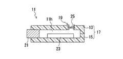
図1に示すのは、本発明の方法で製造した通気フィルタ付き筐体を備えた自動車のECUである。ECU11は、電子部品および配線基板を含むECU本体部23と、通気フィルタ付き筐体17とを備えている。ECU本体部23と外部との電気信号の授受を行うためのコネクタ21が、通気フィルタ付き筐体17の側面部に露出している。Hereinafter, embodiments of the present invention will be described with reference to the accompanying drawings.
FIG. 1 shows an ECU of an automobile provided with a casing with a ventilation filter manufactured by the method of the present invention. The ECU 11 includes an ECU
通気フィルタ付き筐体17は、通気フィルタ部品19を含む筐体上部13(通気フィルタ付き筐体部品)と、その筐体上部13に組み合わされた筐体下部15(他の筐体部分)との2つの部分(複数部分)から構成されている。筐体上部13と筐体下部15とは、シーリング材や接着剤を用いて隙間無く接合されている。コネクタ21と通気フィルタ付き筐体17との間もシールされている。通気フィルタ付き筐体17内の空間11hは、通気フィルタ部品19を通じて外部との換気が行われる。本実施形態では、筐体上部13と筐体下部15の両方を樹脂製としているが、通気フィルタ部品19を含まない筐体下部15は金属製であってもよい。 The
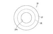
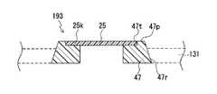
図2は、図1の部分拡大断面図であり、図3は、図2に示す通気フィルタ部品の平面図である。図2に示すように、通気フィルタ部品19は、通気フィルタ25と、その通気フィルタ25の周縁部25kを上下から挟んで固定する支持体27とを備えている。図3の平面図に示すように、通気フィルタ25は円形状である。支持体27は、内径が通気フィルタ25の直径よりも小さく、且つ外径が通気フィルタ25の直径よりも大きいリング状の形態を有する。支持体27の開口27h内に通気フィルタ25の一部が露出し、支持体27の内部に通気フィルタ25の周縁部25kが埋没している。なお、通気フィルタ25や支持体27の形状については、上記に限定されるわけではなく、例えば、方形状の通気フィルタと、その通気フィルタの周縁部を固定する枠状の支持体とからなる通気フィルタ部品を採用することが可能である。 2 is a partially enlarged cross-sectional view of FIG. 1, and FIG. 3 is a plan view of the ventilation filter component shown in FIG. As shown in FIG. 2, the
図2に示すごとく、通気フィルタ部品19は、筐体上部13における通気フィルタ部品19以外の部分である壁部131に一体化されている。具体的には、支持体27が、その側面27rのみで壁部131に一体化されている。支持体27の下面27qと壁部131の内側面13qとが略面一となっており、支持体27の上面27pと壁部131の外側面13pとの境界には段差が生じている。このような固定形態とすることにより、筐体上部13の薄肉化を図ることが可能である。なお、支持体27は、側面27rの全体で壁部131に一体化されていてもよい。その場合には支持体27の上面27pと、壁部131の外側面13pとを略面一にすることにより、通気フィルタ部品19の外方向への突出量を小さくすることができる。 As shown in FIG. 2, the
通気フィルタ25は、気体の通過を許容し、液体の通過を阻止する膜の形態を有するものである。具体的には、例えば、フッ素樹脂やポリオレフィン樹脂の多孔膜を単独で、もしくはその多孔膜と補強材とを組み合わせた複合体を、通気フィルタ25として使用することができる。本実施形態では、多孔膜を単独で通気フィルタ25としている。 The
通気フィルタ25に好適な多孔膜は、撥液性に優れることから、フッ素樹脂の多孔膜であることが好ましく、特に、ポリテトラフルオロエチレン(PTFE)の多孔膜が好ましい。フッ素樹脂の多孔膜は、化学的な耐性にも優れている。PTFEの多孔膜は、PTFE粒子を含むペーストを成形、圧延した後に、延伸することなどにより形成できる。 The porous film suitable for the
上記多孔膜は、撥液処理(撥水処理および/または撥油処理)が施されていてもよい。撥液処理は、表面張力の小さい物質を多孔膜に塗布し、乾燥させた後にキュアすることにより行うことができる。撥液処理に用いる撥液剤には、例えば、パーフルオロアルキル基を有する高分子材料を含む溶液を用いることができる。多孔膜への撥液剤の塗布は、撥液処理として一般的な手法である含浸法やスプレー法で行うとよい。 The porous film may be subjected to a liquid repellent treatment (water repellent treatment and / or oil repellent treatment). The liquid repellent treatment can be performed by applying a substance having a small surface tension to the porous film, drying it and then curing it. As the liquid repellent used for the liquid repellent treatment, for example, a solution containing a polymer material having a perfluoroalkyl group can be used. Application of the liquid repellent to the porous film may be performed by an impregnation method or a spray method, which is a general method for liquid repellent treatment.
多孔膜の厚さは特に限定されないが、通常、50μm〜10mmの範囲である。多孔膜の空孔率および平均孔径も特に限定されないが、液体が実質的に透過しない通気フィルタ25を構成するためには、平均孔径にして、例えば、0.01μm〜10μmの範囲であればよく、0.5μm〜5μmの範囲が好ましい。空孔率にして、例えば、10%〜90%の範囲であればよく、30%〜80%の範囲が好ましい。 Although the thickness of a porous film is not specifically limited, Usually, it is the range of 50 micrometers-10 mm. The porosity and average pore diameter of the porous membrane are not particularly limited, but in order to construct the
多孔膜を補強する補強材には、多孔膜の通気性を妨げないもの、例えば、樹脂や金属などからなる、織布、不織布、メッシュ、ネット、スポンジ、フォーム、発泡体、多孔体などを用いることができる。こうした補強材は、接着剤を用いる方法や、熱溶着または超音波溶着といった方法により、多孔膜と接合することができる。 As the reinforcing material that reinforces the porous membrane, a material that does not interfere with the air permeability of the porous membrane, for example, a woven fabric, a nonwoven fabric, a mesh, a net, a sponge, a foam, a foam, a porous body, or the like made of resin or metal is used. be able to. Such a reinforcing material can be bonded to the porous film by a method using an adhesive, a method such as heat welding or ultrasonic welding.
一方、支持体27は、樹脂製または金属製とすることができるが、樹脂からなる壁部131との一体化のし易さを考慮すると、樹脂製であることが望ましい。支持体27に使用する樹脂は、高温下での使用に耐えうるように、耐熱性を有するエンジニアリングプラスチック、例えば、PBT(ポリブチレンテレフタレート)、ABS(アクリロニトリルブタジエンスチレン)、PS(ポリスチレン)、PC(ポリカーボネート)、PVC(ポリ塩化ビニル)などが好適である。このような樹脂を、例えば射出成形法によって成形して支持体27を得ることができる。 On the other hand, the
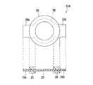
なお、図4に示す筐体上部13Bのように、支持体27の開口27hに蓋29を取り付けてもよい。このような蓋29を有する通気フィルタ部品191によれば、通気フィルタ25を塵芥や水滴等の異物から確実に保護できる。蓋29には、通気孔29pが形成してあるので、通気フィルタ25の通気性を妨げることもない。蓋29は、通気フィルタ25および支持体27を壁部131と一体化した後で、支持体27に取り付けるようにしてもよいし、蓋29を支持体27に取り付けた状態の通気フィルタ部品191を成形型にインサートして、壁部131に一体化するようにしてもよい。また、支持体27の上面27pへの蓋29の接合方法としては、接着剤を用いる方法、熱溶着による方法、または超音波溶着による方法を例示することができる。 In addition, you may attach the lid | cover 29 to the
次に、図1に示した通気フィルタ付き筐体17の製造方法について説明する。
本実施形態で説明する製造方法によれば、通気フィルタ19を含む筐体上部13と、筐体下部15とを別々に製造し、ECU本体部23等の機器を筐体上部13または筐体下部15の所定位置に固定した後、筐体上部13と筐体下部15とを接合して通気フィルタ付き筐体17を完成させる。Next, a manufacturing method of the
According to the manufacturing method described in the present embodiment, the housing
筐体上部13を製造する前に、まず、通気フィルタ部品19を作製する。図1〜図3に示す通気フィルタ部品19は、樹脂製の支持体27を成形する成形型に通気フィルタ25をインサートする、いわゆるインサート成形法によって作製することができる。また、支持体27となるべき上下2つのリング状成形品を先に作製しておき、いずれか一方に通気フィルタ25を固定したのち、2つのリング状成形品の内周部分で通気フィルタ25の周縁部25kを上下から挟み込むような形で、それらリング状成型品同士を接着剤等で接合するという方法によっても、同様の通気フィルタ部品19を作製することができる。 Before manufacturing the housing
次に、予め作製した複数の通気フィルタ部品の検査を実施して良品/不良品を選別し、良品のみを筐体上部13を成形する工程に供する通気フィルタ部品19とする。このようにすれば、筐体上部13の製造後に検査を実施せずに済み、通気フィルタに損傷が生じている等の問題があった場合の無駄を極力省くことができる。 Next, a plurality of preliminarily produced ventilation filter parts are inspected to select non-defective / defective products, and only the non-defective products are used as a
通気フィルタ部品19に実施する検査は、例えば、JIS L 1092(1998)に規定されている繊維製品の防水性試験方法のB法(高水圧法)に準拠した耐水検査である。具体的には、クランプ等に固定した通気フィルタ部品19に対し、表側から、例えば約30kPaの水圧を加える。そして、通気フィルタ25の裏面側に水が漏れていないものを、耐水圧30kPa以上の防水シール特性を有する良品と判断する。なお、JIS L 1092(1998)のB法は破壊試験であるが、本実施形態での耐水検査は、通気フィルタ部品19の破壊強度より十分に低い圧力で行う非破壊試験とする。上記では、水圧を約30kPaとしているが、この値は製品のグレードによって異なる。 The inspection performed on the
また、通気フィルタ部品19には、通気検査を実施することもある。通気検査は、例えば、JIS P 8117に規定されている通気度試験(ガーレー)、あるいはJIS L 1096に規定されている通気度試験(フラジール)に準拠した方法で実施することができる。通気検査では、予め定めた閾値以上の通気度を示すものを良品と判断する。なお、このような通気検査は、上記の耐水検査に代えて、あるいは耐水検査とともに行うことができる。 The
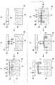
次に、通気フィルタ部品19を成形型内に配置して樹脂成形を行うインサート射出成形法により、通気フィルタ部品19を含む筐体上部13を製造する。図5は筐体上部13を製造する工程の説明図である。使用する成形型50は、可動型40と固定型44とを備えるものである。可動型40は、突出しピン42を有する。固定型44には、通気フィルタ部品19を嵌め込んで位置決めする凹部44cと、ゲート46が形成されている(図5(a))。 Next, the housing
まず、固定型44の凹部44cに通気フィルタ部品19を配置する(図5(b))。続いて、可動型40を固定型44に接近させて型締めする(図5(c))。成形型50は、型締めした状態において、通気フィルタ25の上下に空隙SH,SHが形成される設計になっている。尚且つ、その空隙SH,SHへの樹脂の流れ込みが阻止されるように、換言すれば、通気フィルタ25の通気領域(支持体27の開口27hに露出している領域)への樹脂の流れ込みが阻止されるように、支持体27の上下面27p,27qが成形型50に密着している。このような方法によれば、通気フィルタ部品19を保護フィルム等で別途保護しなくても、通気フィルタ25の通気領域に射出した樹脂が接触することがなく、通気フィルタ25の通気性が損なわれるおそれがない。 First, the
次に、成形型50の内部に形成されたキャビティCVにゲート46を通じて樹脂13aを射出する(図5(d))。キャビティCVに射出された樹脂13aは、通気フィルタ部品19の支持体27の側面27rを隙間無く取り囲み、支持体27と一体化する。筐体上部13の成形に使用する樹脂13a(壁部131を構成する樹脂)としては、通気フィルタ付き筐体17の使用環境が比較的高温になることを考慮し、耐熱性に優れるエンジニアリングプラスチック、例えば、PBT、ABS、PS、PC、PVCなどが好適である。より好ましくは、通気フィルタ部品19の支持体27に使用する樹脂の種類(組成)と、筐体上部13の成形に使用する樹脂13aの種類(組成)とを同一とすることである。同一の樹脂同士であれば相溶性に優れるので、通気フィルタ部品19を筐体上部13に強固に固定することが可能となる。 Next, the
また、支持体27の樹脂の種類と、壁部131の樹脂の種類とを異ならせる場合であっても、PBTなどの耐熱性に優れる樹脂で支持体27を形成しておけば、筐体上部13の成形に比較的高融点の耐熱性に優れる樹脂を使用することが可能となる。また、通気フィルタ25についても、耐熱性に優れるフッ素樹脂(例えばPTFE)等で形成しておけば、成形温度を比較的高く設定しても通気フィルタ25にダメージが及ぶおそれがない。 Even if the resin type of the
キャビティCVに樹脂を射出し終えたら、適切な冷却時間を経て、可動型40を固定型44から離間させて型開きする(図5(e))。そして、突出しピン42を駆動し、通気フィルタ部品19を含む筐体上部13を成形型50から抜き取る(図5(f))。このようにして、通気フィルタ付き筐体17の一部である筐体上部13を得ることができる。なお、図5では、筐体上部13を離型する突出ピン42が通気フィルタ部品19だけに当接する形態を示しているが、実際には、通気フィルタ部品19以外の部分も同時に突出しピンで押し出すようにした方がよい。また、突出しピンが通気フィルタ部品19に接していなければならないというわけでもなく、通気フィルタ部品19以外の部分にのみ突出しピンが接していてもよい。 When the resin has been injected into the cavity CV, the
上記のようにして製造した筐体上部13に組み合わせるべき筐体下部15を、公知の射出成型法によって製造する。そして、ECU本体部23等の機器を筐体下部15の所定位置に固定した後、筐体上部13と筐体下部15とをシーリング材等を用いて接合し、内部が密閉された通気フィルタ付き筐体17、ならびにその筐体17を備えたECU11を完成させる。 The casing
なお、図1〜図3に示す通気フィルタ部品19は、通気フィルタ25の厚さ方向を上下方向としたとき、略上下対称であることが望ましい。このようにすれば、通気フィルタ部品19を上下いずれの向きからでも成形型50の凹部44cに嵌め込むことができるようになるので、作業性が向上する、自動化が容易になる等の利点が生ずる。 In addition, as for the
また、図13に示すように、通気フィルタ部品19を含む有底筒状の通気フィルタ付き筐体部品171を製造し、その通気フィルタ付き筐体部品171の開口部を蓋体172で塞ぐことにより、通気フィルタ付き筐体を得るようにしてもよい。もちろん、通気フィルタ部品19が蓋体172の方に一体化されていてもよい。 Further, as shown in FIG. 13, by manufacturing a bottomed
(第二実施形態)
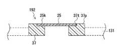
図5で説明した製造方法は、図6に示すような通気フィルタ部品192を用いて実施することも可能である。図6に示す通気フィルタ部品192は、通気フィルタ25と、その通気フィルタ25の厚さと略等しい深さの座ぐり37tを有する支持体37とを備えたものである。樹脂製の支持体37を先に作製しておき、その支持体37の座ぐり37tに通気フィルタ25を後から固定している。このような通気フィルタ部品192は、図1〜図3の通気フィルタ部品19に比べて簡単に作製できるという利点がある。(Second embodiment)
The manufacturing method described with reference to FIG. 5 can also be implemented using a
また、図5で説明した製造方法は、図7に示すような通気フィルタ部品193を用いて実施することが可能である。図7に示す通気フィルタ部品193は、図6で説明した通気フィルタ部品192の変形例である。具体的には、図7に示すように、通気フィルタ部品193は、通気フィルタ25の厚さ方向に平行な断面において、通気フィルタ25の厚さ方向から所定角度傾くように支持体47の側面47rにテーパを付けている。このような通気フィルタ部品193が壁部131に一体化された筐体上部を得るには、図8に示すように、成形型45の凹部45cにも併せて角度θのテーパを付与する。このようにすれば、支持体47と筐体上部との接合面積を増加させることができるので、通気フィルタ部品193と壁部131との接合強度を高めることができる。なお、支持体47の側面47rに付与するテーパの角度θは、例えば、通常の射出成形の抜きテーパ(例えば1度未満)よりも大きく、45度を超えない範囲で適宜調整すればよい。また、支持体の側面にテーパを付与することは、他の実施形態に適用してもよい。 Moreover, the manufacturing method demonstrated in FIG. 5 can be implemented using the
また、図6,7に示す通気フィルタ部品192,193が壁部131に一体化された筐体上部をインサート成形によって作製するには、支持体37,47に形成する座ぐり37t,47tの深さを、通気フィルタ25の厚さと略一致するか、やや深く調整しておくとよい。そのようにすれば、通気フィルタ部品192,193を成形型に配置して型締めしたとき、それら通気フィルタ部品192,193の支持体37,47の上面37p,47pと成形型との間に隙間が生じなくなって、通気フィルタ25の通気領域に樹脂が流れ込むおそれが小さくなる。 Further, in order to produce the upper part of the housing in which the
(第三実施形態)
図5に説明した製造方法は、図9に示す通気フィルタ部品194を用いて実施することも可能である。図9の上段は平面図であり、下段は断面図を表している。通気フィルタ部品194は、通気フィルタ26の厚さ方向に垂直な面内方向において、通気フィルタ26の周縁部26kの一部が支持体30の外周縁よりも外側に食み出した形態を有するものである。ただし、平面図から理解できるように、通気フィルタ26の周縁部の残りは、支持体30に埋まっている。したがって、通気フィルタ26を支持体30に固定していることには変わりない。(Third embodiment)
The manufacturing method described in FIG. 5 can also be implemented using the
上記のような通気フィルタ部品194が壁部131に一体化された筐体上部をインサート成形法によって製造するには、図10に示すように、成形型50の型締め状態において、支持体30から食み出した通気フィルタ26の周縁部26kをキャビティCV内に露出させる。そして、キャビティCVに樹脂を射出したときには、射出した樹脂で食み出した周縁部26kを包み込むようにして通気フィルタ部品194(具体的には支持体30)をキャビティCV内に射出した樹脂に一体化させる。このようにすれば、図11に示すように、支持体30と壁部131との両者にまたがる形で、通気フィルタ25をしっかりと固定することが可能となる。 In order to manufacture the upper part of the housing in which the
なお、図12の平面図に示すように、通気フィルタ56に貫通孔56pを形成しておき、その貫通孔56pに支持体50の一部を貫入することによって、通気フィルタ56を支持体50に固定した通気フィルタ部品195を採用することも可能である。このような通気フィルタ部品195によれば、通気フィルタ56の周縁部56kが周方向の全域にわたって、支持体50の外周縁よりも外側に食み出ることになる。 As shown in the plan view of FIG. 12, a through
ランプ類、モータ、センサ、スイッチ、ECU等の自動車の機器、あるいは移動体通信機器、カメラ、電気剃刀、電動歯ブラシ等の電気機器に用いる通気フィルタ付き筐体を、本発明の方法によって好適に製造することができる。 The method of the present invention suitably manufactures a casing with a ventilation filter used for electric devices such as lamps, motors, sensors, switches, ECUs, etc., or mobile communication devices, cameras, electric razors, electric toothbrushes, etc. can do.
13 筐体上部
15 筐体下部
17,171 通気フィルタ付き筐体
19,191,192,193,194,195 通気フィルタ部品
25,26,56 通気フィルタ
25k,26k,56k 周縁部
27,30,37,47,50 支持体
40 可動型
44,45 固定型
50 成形型
131 壁部
SH 空隙
CV キャビティ
13 Case
Claims (10)
Translated fromJapanese前記成形型が前記支持体の上下面に密着して、前記通気フィルタの上下に形成される空隙への前記樹脂の流れ込みが阻止されるように前記成形型を型締めする、請求項1記載の通気フィルタ付き筐体部品の製造方法。The support has a frame-like form to fix the air filter by sandwiching the peripheral edge from above and below,
Said mold in close contact with the upper and lower surfaces of the support, wherein for clamping the mold as inflow of the resin into the gap formed above and below the ventilation filter is prevented, according to claim1, wherein A method for manufacturing a casing component with a ventilation filter.
Priority Applications (6)
| Application Number | Priority Date | Filing Date | Title |
|---|---|---|---|
| JP2005354954AJP4717618B2 (en) | 2005-12-08 | 2005-12-08 | Manufacturing method of casing component with ventilation filter and manufacturing method of casing with ventilation filter |
| KR1020087016428AKR101211251B1 (en) | 2005-12-08 | 2006-11-15 | Method for manufacture of housing part provided with ventilation filter, and method for manufacture of housing provided with ventilation filter |
| EP06823405.3AEP1964658B1 (en) | 2005-12-08 | 2006-11-15 | Method for manufacture of housing part provided with ventilation filter, and method for manufacture of housing provided with ventilation filter |
| PCT/JP2006/322751WO2007066477A1 (en) | 2005-12-08 | 2006-11-15 | Method for manufacture of housing part provided with ventilation filter, and method for manufacture of housing provided with ventilation filter |
| CN2006800463721ACN101326043B (en) | 2005-12-08 | 2006-11-15 | Method for manufacture of housing part provided with ventilation filter, and method for manufacture of housing provided with ventilation filter |
| US12/086,035US8178023B2 (en) | 2005-12-08 | 2006-11-15 | Method for manufacture of housing part provided with ventilation filter, and method for manufacture of housing provided with ventilation filter |
Applications Claiming Priority (1)
| Application Number | Priority Date | Filing Date | Title |
|---|---|---|---|
| JP2005354954AJP4717618B2 (en) | 2005-12-08 | 2005-12-08 | Manufacturing method of casing component with ventilation filter and manufacturing method of casing with ventilation filter |
Publications (2)
| Publication Number | Publication Date |
|---|---|
| JP2007152891A JP2007152891A (en) | 2007-06-21 |
| JP4717618B2true JP4717618B2 (en) | 2011-07-06 |
Family
ID=38122627
Family Applications (1)
| Application Number | Title | Priority Date | Filing Date |
|---|---|---|---|
| JP2005354954AExpired - Fee RelatedJP4717618B2 (en) | 2005-12-08 | 2005-12-08 | Manufacturing method of casing component with ventilation filter and manufacturing method of casing with ventilation filter |
Country Status (6)
| Country | Link |
|---|---|
| US (1) | US8178023B2 (en) |
| EP (1) | EP1964658B1 (en) |
| JP (1) | JP4717618B2 (en) |
| KR (1) | KR101211251B1 (en) |
| CN (1) | CN101326043B (en) |
| WO (1) | WO2007066477A1 (en) |
Families Citing this family (54)
| Publication number | Priority date | Publication date | Assignee | Title |
|---|---|---|---|---|
| US9675109B2 (en) | 2005-07-19 | 2017-06-13 | J. T. International Sa | Method and system for vaporization of a substance |
| US20160345631A1 (en) | 2005-07-19 | 2016-12-01 | James Monsees | Portable devices for generating an inhalable vapor |
| US8991402B2 (en) | 2007-12-18 | 2015-03-31 | Pax Labs, Inc. | Aerosol devices and methods for inhaling a substance and uses thereof |
| JP5282871B2 (en)* | 2008-05-30 | 2013-09-04 | ローム株式会社 | Fuel cell and manufacturing method thereof |
| EP2290734A4 (en)* | 2008-05-26 | 2014-04-16 | Rohm Co Ltd | FUEL CELL AND METHOD FOR MANUFACTURING THE SAME |
| JP2010000464A (en)* | 2008-06-20 | 2010-01-07 | Japan Gore Tex Inc | Vent filter and method for manufacturing thereof |
| US20100068431A1 (en)* | 2008-09-17 | 2010-03-18 | Vishal Bansal | Article and method for forming an article |
| JP5434669B2 (en)* | 2010-02-26 | 2014-03-05 | 株式会社デンソー | Waterproof housing and waterproof device |
| WO2013109312A1 (en)* | 2012-01-19 | 2013-07-25 | Dow Global Technologies Llc | Article and method for venting a processing vessel |
| US20130248385A1 (en) | 2012-03-23 | 2013-09-26 | Njoy, Inc. | Electronic cigarette container |
| US20130247924A1 (en) | 2012-03-23 | 2013-09-26 | Mark Scatterday | Electronic cigarette having a flexible and soft configuration |
| JP5947655B2 (en)* | 2012-08-02 | 2016-07-06 | 日東電工株式会社 | Polytetrafluoroethylene porous membrane, and ventilation membrane and ventilation member using the same |
| US10517530B2 (en) | 2012-08-28 | 2019-12-31 | Juul Labs, Inc. | Methods and devices for delivering and monitoring of tobacco, nicotine, or other substances |
| JP2014151767A (en)* | 2013-02-08 | 2014-08-25 | Nitto Denko Corp | Ventilation member and ventilation structure |
| CN105263345A (en) | 2013-05-06 | 2016-01-20 | 派克斯实验公司 | Nicotine salt formulations for aerosol devices and methods thereof |
| WO2014190079A2 (en) | 2013-05-22 | 2014-11-27 | Njoy, Inc. | Compositions, devices, and methods for nicotine aerosol delivery |
| CN105473012B (en) | 2013-06-14 | 2020-06-19 | 尤尔实验室有限公司 | Multiple heating elements with separate vaporizable materials in electronic vaporization equipment |
| USD763083S1 (en) | 2013-11-08 | 2016-08-09 | W.L. Gore & Associates, Gmbh | Vent cap |
| USD748472S1 (en) | 2013-11-08 | 2016-02-02 | W.L. Gore & Associates Gmbh | Vent |
| JP2015111094A (en)* | 2013-11-11 | 2015-06-18 | 日本特殊陶業株式会社 | Combustible gas sensor, and manufacturing method thereof |
| CN105765992B (en)* | 2013-11-18 | 2019-08-20 | 日东电工株式会社 | Waterproof and sound-permeable membrane and waterproof and sound-permeable structure using waterproof and sound-permeable membrane |
| USD721577S1 (en) | 2013-11-21 | 2015-01-27 | Njoy, Inc. | Packaging assembly |
| KR20240070710A (en) | 2013-12-05 | 2024-05-21 | 쥴 랩스, 인크. | Nicotine liquid formulations for aerosol devices and methods thereof |
| US10159282B2 (en) | 2013-12-23 | 2018-12-25 | Juul Labs, Inc. | Cartridge for use with a vaporizer device |
| USD842536S1 (en) | 2016-07-28 | 2019-03-05 | Juul Labs, Inc. | Vaporizer cartridge |
| USD825102S1 (en) | 2016-07-28 | 2018-08-07 | Juul Labs, Inc. | Vaporizer device with cartridge |
| US10058129B2 (en) | 2013-12-23 | 2018-08-28 | Juul Labs, Inc. | Vaporization device systems and methods |
| US10076139B2 (en) | 2013-12-23 | 2018-09-18 | Juul Labs, Inc. | Vaporizer apparatus |
| US20160366947A1 (en) | 2013-12-23 | 2016-12-22 | James Monsees | Vaporizer apparatus |
| US9549573B2 (en) | 2013-12-23 | 2017-01-24 | Pax Labs, Inc. | Vaporization device systems and methods |
| DE202014011260U1 (en) | 2013-12-23 | 2018-11-13 | Juul Labs Uk Holdco Limited | Systems for an evaporation device |
| USD749197S1 (en) | 2014-02-24 | 2016-02-09 | W. L. Gore & Associates Gmbh | Vent cap |
| USD748227S1 (en) | 2014-02-24 | 2016-01-26 | W. L. Gore & Associates Gmbh | Vent cap |
| US9089166B1 (en) | 2014-05-09 | 2015-07-28 | Njoy, Inc. | Packaging for vaporizing device |
| US9010335B1 (en) | 2014-05-13 | 2015-04-21 | Njoy, Inc. | Mechanisms for vaporizing devices |
| WO2015175979A1 (en) | 2014-05-16 | 2015-11-19 | Pax Labs, Inc. | Systems and methods for aerosolizing a smokeable material |
| US11350669B2 (en) | 2014-08-22 | 2022-06-07 | Njoy, Llc | Heating control for vaporizing device |
| MX394125B (en) | 2014-12-05 | 2025-03-24 | Juul Labs Inc | CALIBRATED DOSE CONTROL |
| CN105984073A (en)* | 2015-02-16 | 2016-10-05 | 南京瑞安电气有限公司 | Production equipment for cylindrical filter |
| US10251425B2 (en) | 2015-07-06 | 2019-04-09 | Njoy, Llc | Vaporizing device with power component |
| USD809190S1 (en) | 2015-07-13 | 2018-01-30 | Njoy, Llc | Vaporizer |
| US10039323B2 (en) | 2015-07-16 | 2018-08-07 | Njoy, Llc | Vaporizer tank with atomizer |
| EP3413960B1 (en) | 2016-02-11 | 2021-03-31 | Juul Labs, Inc. | Fillable vaporizer cartridge and method of filling |
| CO2018009342A2 (en) | 2016-02-11 | 2018-09-20 | Juul Labs Inc | Secure fixing cartridges for vaporizing devices |
| WO2017147004A1 (en) | 2016-02-25 | 2017-08-31 | Donaldson Company, Inc. | Liquid reservoir shutoff vent |
| US10405582B2 (en) | 2016-03-10 | 2019-09-10 | Pax Labs, Inc. | Vaporization device with lip sensing |
| USD849996S1 (en) | 2016-06-16 | 2019-05-28 | Pax Labs, Inc. | Vaporizer cartridge |
| USD851830S1 (en) | 2016-06-23 | 2019-06-18 | Pax Labs, Inc. | Combined vaporizer tamp and pick tool |
| USD836541S1 (en) | 2016-06-23 | 2018-12-25 | Pax Labs, Inc. | Charging device |
| USD848057S1 (en) | 2016-06-23 | 2019-05-07 | Pax Labs, Inc. | Lid for a vaporizer |
| US11660403B2 (en) | 2016-09-22 | 2023-05-30 | Juul Labs, Inc. | Leak-resistant vaporizer device |
| JP6777511B2 (en)* | 2016-11-22 | 2020-10-28 | 株式会社日立製作所 | Ultrasound imaging device |
| USD887632S1 (en) | 2017-09-14 | 2020-06-16 | Pax Labs, Inc. | Vaporizer cartridge |
| CN116135175A (en)* | 2023-03-16 | 2023-05-19 | 北京牙牙日记科技有限公司 | an electric toothbrush |
Family Cites Families (13)
| Publication number | Priority date | Publication date | Assignee | Title |
|---|---|---|---|---|
| US4113627A (en)* | 1976-01-28 | 1978-09-12 | Filtertek, Inc. | Process for making hermetically sealed filter units and filters made thereby |
| JPH0751211B2 (en)* | 1988-02-26 | 1995-06-05 | ニッポー株式会社 | Vent and manufacturing method thereof |
| JPH0239909A (en)* | 1988-07-29 | 1990-02-08 | Nok Corp | Wire mesh screen with resin frame and its manufacture |
| JP3219700B2 (en)* | 1996-09-18 | 2001-10-15 | 日東電工株式会社 | Vent filter member |
| US5766472A (en)* | 1996-10-29 | 1998-06-16 | Illinois Tool Works Inc. | Method and apparatus for a filter assembly |
| JP4179680B2 (en)* | 1998-10-12 | 2008-11-12 | 富士通コンポーネント株式会社 | Electronic component carrier, electronic component package, and electronic component carrying method |
| ES2179604T3 (en)* | 1999-09-29 | 2003-01-16 | Millipore S A S | PROCEDURE FOR SEALING A FILTER ELEMENT IN A FILTER CARTRIDGE AND FILTER DEVICES PRODUCED FROM THE SAME. |
| JP4137325B2 (en)* | 1999-12-09 | 2008-08-20 | 日東電工株式会社 | Ventilation enclosure |
| JP2002039394A (en)* | 2000-07-21 | 2002-02-06 | Nok Corp | Gasket with filter |
| JP2002347068A (en)* | 2001-05-29 | 2002-12-04 | Tokai Kogyo Co Ltd | Resin molded product having air permeable part in part thereof and method for manufacturing the same |
| JP3961816B2 (en)* | 2001-11-15 | 2007-08-22 | 東海興業株式会社 | Case member and manufacturing method thereof |
| JP4122411B2 (en)* | 2002-09-17 | 2008-07-23 | 京三電機株式会社 | Insert molding material |
| JP2005011587A (en)* | 2003-06-17 | 2005-01-13 | Tokai Rika Co Ltd | Press-fit pin, insulator, and insertion molding method |
- 2005
- 2005-12-08JPJP2005354954Apatent/JP4717618B2/ennot_activeExpired - Fee Related
- 2006
- 2006-11-15EPEP06823405.3Apatent/EP1964658B1/ennot_activeNot-in-force
- 2006-11-15KRKR1020087016428Apatent/KR101211251B1/ennot_activeExpired - Fee Related
- 2006-11-15USUS12/086,035patent/US8178023B2/ennot_activeExpired - Fee Related
- 2006-11-15CNCN2006800463721Apatent/CN101326043B/ennot_activeExpired - Fee Related
- 2006-11-15WOPCT/JP2006/322751patent/WO2007066477A1/enactiveApplication Filing
Also Published As
| Publication number | Publication date |
|---|---|
| KR20080086487A (en) | 2008-09-25 |
| CN101326043B (en) | 2012-01-25 |
| EP1964658B1 (en) | 2015-10-14 |
| EP1964658A1 (en) | 2008-09-03 |
| WO2007066477A1 (en) | 2007-06-14 |
| US20090267252A1 (en) | 2009-10-29 |
| KR101211251B1 (en) | 2012-12-11 |
| CN101326043A (en) | 2008-12-17 |
| JP2007152891A (en) | 2007-06-21 |
| EP1964658A4 (en) | 2013-07-17 |
| US8178023B2 (en) | 2012-05-15 |
Similar Documents
| Publication | Publication Date | Title |
|---|---|---|
| JP4717618B2 (en) | Manufacturing method of casing component with ventilation filter and manufacturing method of casing with ventilation filter | |
| US8727844B2 (en) | Ventilation member and method of manufacturing the same | |
| EP2787277B1 (en) | Ventilation member | |
| JP4855203B2 (en) | Ventilation member and ventilation structure | |
| US6827232B1 (en) | Resin case providing compatibility between air permeability and water proofing property, and mold for producing such case | |
| JP6486014B2 (en) | Gas permeable member and manufacturing method thereof | |
| KR20010049300A (en) | Air-permeable cap and outdoor lamp, automobile lamp and automobile electrical component comprising same | |
| WO2007069387A1 (en) | Ventilating member and ventilating structure | |
| EP2560469A1 (en) | Venting device comprising a seal protection | |
| JP5508044B2 (en) | Ventilation cap and manufacturing method thereof | |
| JP5253291B2 (en) | Ventilation member and ventilation structure | |
| JP4425067B2 (en) | Manufacturing method of ventilation member | |
| JP7446233B2 (en) | ventilation casing | |
| US20050046081A1 (en) | Resin case in which gas-permeability and waterproof quality are compatible, and die for manufacturing such case | |
| JP4338677B2 (en) | Case parts and manufacturing method thereof | |
| EP2390560B1 (en) | Air-permeable member and process for producing same | |
| JP4574339B2 (en) | Manufacturing method of ventilation member | |
| JP2009056441A (en) | Ventilation member |
Legal Events
| Date | Code | Title | Description |
|---|---|---|---|
| A621 | Written request for application examination | Free format text:JAPANESE INTERMEDIATE CODE: A621 Effective date:20071113 | |
| A131 | Notification of reasons for refusal | Free format text:JAPANESE INTERMEDIATE CODE: A131 Effective date:20100406 | |
| A521 | Request for written amendment filed | Free format text:JAPANESE INTERMEDIATE CODE: A523 Effective date:20100603 | |
| TRDD | Decision of grant or rejection written | ||
| A01 | Written decision to grant a patent or to grant a registration (utility model) | Free format text:JAPANESE INTERMEDIATE CODE: A01 Effective date:20110329 | |
| A01 | Written decision to grant a patent or to grant a registration (utility model) | Free format text:JAPANESE INTERMEDIATE CODE: A01 | |
| A61 | First payment of annual fees (during grant procedure) | Free format text:JAPANESE INTERMEDIATE CODE: A61 Effective date:20110330 | |
| R150 | Certificate of patent or registration of utility model | Ref document number:4717618 Country of ref document:JP Free format text:JAPANESE INTERMEDIATE CODE: R150 Free format text:JAPANESE INTERMEDIATE CODE: R150 | |
| FPAY | Renewal fee payment (event date is renewal date of database) | Free format text:PAYMENT UNTIL: 20140408 Year of fee payment:3 | |
| R250 | Receipt of annual fees | Free format text:JAPANESE INTERMEDIATE CODE: R250 | |
| R250 | Receipt of annual fees | Free format text:JAPANESE INTERMEDIATE CODE: R250 | |
| R250 | Receipt of annual fees | Free format text:JAPANESE INTERMEDIATE CODE: R250 | |
| R250 | Receipt of annual fees | Free format text:JAPANESE INTERMEDIATE CODE: R250 | |
| R250 | Receipt of annual fees | Free format text:JAPANESE INTERMEDIATE CODE: R250 | |
| LAPS | Cancellation because of no payment of annual fees |