JP4716949B2 - Image processing apparatus and image processing method - Google Patents
Image processing apparatus and image processing methodDownload PDFInfo
- Publication number
- JP4716949B2 JP4716949B2JP2006217563AJP2006217563AJP4716949B2JP 4716949 B2JP4716949 B2JP 4716949B2JP 2006217563 AJP2006217563 AJP 2006217563AJP 2006217563 AJP2006217563 AJP 2006217563AJP 4716949 B2JP4716949 B2JP 4716949B2
- Authority
- JP
- Japan
- Prior art keywords
- code
- data
- level
- hierarchy
- code data
- Prior art date
- Legal status (The legal status is an assumption and is not a legal conclusion. Google has not performed a legal analysis and makes no representation as to the accuracy of the status listed.)
- Expired - Fee Related
Links
Images


Classifications
- H—ELECTRICITY
- H04—ELECTRIC COMMUNICATION TECHNIQUE
- H04N—PICTORIAL COMMUNICATION, e.g. TELEVISION
- H04N1/00—Scanning, transmission or reproduction of documents or the like, e.g. facsimile transmission; Details thereof
- H04N1/46—Colour picture communication systems
- H04N1/64—Systems for the transmission or the storage of the colour picture signal; Details therefor, e.g. coding or decoding means therefor
- H—ELECTRICITY
- H04—ELECTRIC COMMUNICATION TECHNIQUE
- H04N—PICTORIAL COMMUNICATION, e.g. TELEVISION
- H04N19/00—Methods or arrangements for coding, decoding, compressing or decompressing digital video signals
- H04N19/10—Methods or arrangements for coding, decoding, compressing or decompressing digital video signals using adaptive coding
- H04N19/134—Methods or arrangements for coding, decoding, compressing or decompressing digital video signals using adaptive coding characterised by the element, parameter or criterion affecting or controlling the adaptive coding
- H04N19/164—Feedback from the receiver or from the transmission channel
- H—ELECTRICITY
- H04—ELECTRIC COMMUNICATION TECHNIQUE
- H04N—PICTORIAL COMMUNICATION, e.g. TELEVISION
- H04N19/00—Methods or arrangements for coding, decoding, compressing or decompressing digital video signals
- H04N19/10—Methods or arrangements for coding, decoding, compressing or decompressing digital video signals using adaptive coding
- H04N19/169—Methods or arrangements for coding, decoding, compressing or decompressing digital video signals using adaptive coding characterised by the coding unit, i.e. the structural portion or semantic portion of the video signal being the object or the subject of the adaptive coding
- H04N19/188—Methods or arrangements for coding, decoding, compressing or decompressing digital video signals using adaptive coding characterised by the coding unit, i.e. the structural portion or semantic portion of the video signal being the object or the subject of the adaptive coding the unit being a video data packet, e.g. a network abstraction layer [NAL] unit
- H—ELECTRICITY
- H04—ELECTRIC COMMUNICATION TECHNIQUE
- H04N—PICTORIAL COMMUNICATION, e.g. TELEVISION
- H04N19/00—Methods or arrangements for coding, decoding, compressing or decompressing digital video signals
- H04N19/42—Methods or arrangements for coding, decoding, compressing or decompressing digital video signals characterised by implementation details or hardware specially adapted for video compression or decompression, e.g. dedicated software implementation
- H04N19/423—Methods or arrangements for coding, decoding, compressing or decompressing digital video signals characterised by implementation details or hardware specially adapted for video compression or decompression, e.g. dedicated software implementation characterised by memory arrangements
- H—ELECTRICITY
- H04—ELECTRIC COMMUNICATION TECHNIQUE
- H04N—PICTORIAL COMMUNICATION, e.g. TELEVISION
- H04N19/00—Methods or arrangements for coding, decoding, compressing or decompressing digital video signals
- H04N19/46—Embedding additional information in the video signal during the compression process
- H—ELECTRICITY
- H04—ELECTRIC COMMUNICATION TECHNIQUE
- H04N—PICTORIAL COMMUNICATION, e.g. TELEVISION
- H04N19/00—Methods or arrangements for coding, decoding, compressing or decompressing digital video signals
- H04N19/60—Methods or arrangements for coding, decoding, compressing or decompressing digital video signals using transform coding
- H04N19/63—Methods or arrangements for coding, decoding, compressing or decompressing digital video signals using transform coding using sub-band based transform, e.g. wavelets
- H—ELECTRICITY
- H04—ELECTRIC COMMUNICATION TECHNIQUE
- H04N—PICTORIAL COMMUNICATION, e.g. TELEVISION
- H04N19/00—Methods or arrangements for coding, decoding, compressing or decompressing digital video signals
- H04N19/70—Methods or arrangements for coding, decoding, compressing or decompressing digital video signals characterised by syntax aspects related to video coding, e.g. related to compression standards
- H—ELECTRICITY
- H04—ELECTRIC COMMUNICATION TECHNIQUE
- H04N—PICTORIAL COMMUNICATION, e.g. TELEVISION
- H04N21/00—Selective content distribution, e.g. interactive television or video on demand [VOD]
- H04N21/20—Servers specifically adapted for the distribution of content, e.g. VOD servers; Operations thereof
- H04N21/23—Processing of content or additional data; Elementary server operations; Server middleware
- H04N21/234—Processing of video elementary streams, e.g. splicing of video streams or manipulating encoded video stream scene graphs
- H04N21/2343—Processing of video elementary streams, e.g. splicing of video streams or manipulating encoded video stream scene graphs involving reformatting operations of video signals for distribution or compliance with end-user requests or end-user device requirements
- H04N21/234327—Processing of video elementary streams, e.g. splicing of video streams or manipulating encoded video stream scene graphs involving reformatting operations of video signals for distribution or compliance with end-user requests or end-user device requirements by decomposing into layers, e.g. base layer and one or more enhancement layers
- H—ELECTRICITY
- H04—ELECTRIC COMMUNICATION TECHNIQUE
- H04N—PICTORIAL COMMUNICATION, e.g. TELEVISION
- H04N21/00—Selective content distribution, e.g. interactive television or video on demand [VOD]
- H04N21/40—Client devices specifically adapted for the reception of or interaction with content, e.g. set-top-box [STB]; Operations thereof
- H04N21/43—Processing of content or additional data, e.g. demultiplexing additional data from a digital video stream; Elementary client operations, e.g. monitoring of home network or synchronising decoder's clock; Client middleware
- H04N21/433—Content storage operation, e.g. storage operation in response to a pause request, caching operations
- H04N21/4332—Content storage operation, e.g. storage operation in response to a pause request, caching operations by placing content in organized collections, e.g. local EPG data repository
- H—ELECTRICITY
- H04—ELECTRIC COMMUNICATION TECHNIQUE
- H04N—PICTORIAL COMMUNICATION, e.g. TELEVISION
- H04N21/00—Selective content distribution, e.g. interactive television or video on demand [VOD]
- H04N21/60—Network structure or processes for video distribution between server and client or between remote clients; Control signalling between clients, server and network components; Transmission of management data between server and client, e.g. sending from server to client commands for recording incoming content stream; Communication details between server and client
- H04N21/63—Control signaling related to video distribution between client, server and network components; Network processes for video distribution between server and clients or between remote clients, e.g. transmitting basic layer and enhancement layers over different transmission paths, setting up a peer-to-peer communication via Internet between remote STB's; Communication protocols; Addressing
- H04N21/647—Control signaling between network components and server or clients; Network processes for video distribution between server and clients, e.g. controlling the quality of the video stream, by dropping packets, protecting content from unauthorised alteration within the network, monitoring of network load, bridging between two different networks, e.g. between IP and wireless
- H04N21/64784—Data processing by the network
- H04N21/64792—Controlling the complexity of the content stream, e.g. by dropping packets
Landscapes
- Engineering & Computer Science (AREA)
- Multimedia (AREA)
- Signal Processing (AREA)
- Computer Networks & Wireless Communication (AREA)
- Databases & Information Systems (AREA)
- Computer Security & Cryptography (AREA)
- Compression Of Band Width Or Redundancy In Fax (AREA)
- Compression Or Coding Systems Of Tv Signals (AREA)
Description
Translated fromJapaneseこの発明は、キャッシュモデルを用いて部分画像の符号化データをアクセスする画像処理装置に関し、特に、キャッシュなどの記憶装置上に保存されている符号データの符号列(パケット)間の関係を示す階層構造を推定し、該階層構造に基づいて保存された符号データの符号列を参照し、キャッシュなどの記憶装置上のデータ参照構造を生成する画像処理装置に関するものである。 The present invention relates to an image processing apparatus that accesses encoded data of a partial image using a cache model, and in particular, a hierarchy indicating a relationship between code strings (packets) of code data stored on a storage device such as a cache. The present invention relates to an image processing apparatus that estimates a structure, refers to a code string of code data stored based on the hierarchical structure, and generates a data reference structure on a storage device such as a cache.
一般に、階層構造に基づいて保存された部分画像の符号化データをキャッシュモデルを用いてアクセスする画像処理装置が知られている。そして、次世代の画像符号化方式であるJPEG2000に準拠した符号化処理を全てハードウェア回路で実現する画像処理装置が提案されている。
ここで、符号データは、一般的に符号データを構成する符号列(パケット)単位にキャッシュに保存される。キャッシュ上の符号列を使用する場合は符号列(パケット)単位に必要な符号列を集めて参照する。In general, an image processing apparatus that accesses encoded data of a partial image stored based on a hierarchical structure using a cache model is known. Then, an image processing apparatus has been proposed that implements all the encoding processing compliant with JPEG2000, which is a next-generation image encoding method, with a hardware circuit.
Here, the code data is generally stored in a cache in units of code strings (packets) constituting the code data. When the code string on the cache is used, the necessary code strings are collected and referenced for each code string (packet).
次に、JPEG2000の基本となる階層符号化アルゴリズムについて説明する。
図25は、JPEG2000の基本となる階層符号化アルゴリズムの説明図である。2次元ウェーブレット変換・逆変換部、量子化・逆量子化部、エントロピー符号化・復号化部、タグ処理部で構成されている。JPEGアルゴリズムと比較して、最も大きく異なる点の一つは変換方法である。JPEGでは離散コサイン変換(以下、DCT:Discrete Cosine Transform)を、階層符号化アルゴリズムでは離散ウェーブレット変換(以下、DWT:Discrete Wavelet Transform)を、各々用いている。DWTはDCTに比べて、高圧縮領域における画質が良いという長所が、JPEG(Joint Photographic Expert Group)の後継アルゴリズムであるJPEG2000で採用された大きな理由の一つとなっている。また、他の大きな相違点は、JPEG2000では、処理の最終段に符号形成をおこなうために、タグ処理部と呼ばれる機能ブロックが追加されていることである。この部分で、符号化動作時には符号データがコード・ストリームとして生成され、復号動作時には復号に必要なコード・ストリームの解釈が行われる。そして、コード・ストリームによって、JPEG2000は様々な便利な機能を実現できるようになった。例えば、図26に示した様に、ブロック・ベースでのDWTにおけるオクターブ分割に対応した任意の階層(デコンポジション・レベル)で、静止画像の圧縮伸長動作を自由に停止させることができるようになる。Next, a hierarchical encoding algorithm that is the basis of JPEG2000 will be described.
FIG. 25 is an explanatory diagram of a hierarchical encoding algorithm that is the basis of JPEG2000. It consists of a two-dimensional wavelet transform / inverse transform unit, a quantization / inverse quantization unit, an entropy encoding / decoding unit, and a tag processing unit. One of the biggest differences compared to the JPEG algorithm is the conversion method. JPEG uses discrete cosine transform (DCT: Discrete Cosine Transform), and hierarchical coding algorithms use discrete wavelet transform (DWT: Discrete Wavelet Transform). The advantage that DWT has better image quality in the high compression region than DCT is one of the major reasons adopted by JPEG2000, which is a successor algorithm of JPEG (Joint Photographic Expert Group). Another major difference is that, in JPEG 2000, a function block called a tag processing unit is added in order to perform code formation at the final stage of processing. In this part, code data is generated as a code stream during the encoding operation, and the code stream necessary for decoding is interpreted during the decoding operation. And with the code stream, JPEG2000 can realize various convenient functions. For example, as shown in FIG. 26, the compression / decompression operation of a still image can be freely stopped at an arbitrary hierarchy (decomposition level) corresponding to octave division in block-based DWT. .
なお、原画像の入出力部分には、色空間変換部が接続されることが多い。例えば、原色系のR(赤)/G(緑)/B(青)の各コンポーネントからなるRGB表色系や、補色系のY(黄)/M(マゼンタ)/C(シアン)の各コンポーネントからなるYMC表色系から、YUVあるいはYCbCr表色系への変換又は逆の変換を行う部分がこれに相当する。 A color space conversion unit is often connected to the input / output portion of the original image. For example, the RGB color system composed of R (red) / G (green) / B (blue) components of the primary color system and the Y (yellow) / M (magenta) / C (cyan) components of the complementary color system This corresponds to the part that performs conversion from the YMC color system consisting of the above to the YUV or YCbCr color system or the reverse conversion.
以下、JPEG2000アルゴリズムについて、少し詳しく説明する。
カラー画像は、一般に、図27に示すように、原画像の各コンポーネント(ここではRGB原色系)が、矩形をした領域(タイル)によって分割される。そして、個々のタイル、例えば、R00、R01、…、R15/G00、G01、…、G15/B00、B01、…、B15が、圧縮伸長プロセスを実行する際の基本単位となる。従って、圧縮伸長動作は、コンポーネント毎、そしてタイル毎に、独立に行なわれる。
符号化時には、各コンポーネントの各タイルのデータが、図25の色空間変換部に入力され、色空間変換を施されたのち、2次元ウェーブレット変換部で2次元ウェーブレット変換(順変換)が適用されて周波数帯に空間分割される。Hereinafter, the JPEG2000 algorithm will be described in detail.
In general, as shown in FIG. 27, a color image is obtained by dividing each component (in this case, the RGB primary color system) of an original image by a rectangular area (tile). Individual tiles such as R00, R01,..., R15 / G00, G01,..., G15 / B00, B01,. Therefore, the compression / decompression operation is performed independently for each component and for each tile.
At the time of encoding, the data of each tile of each component is input to the color space conversion unit in FIG. 25 and subjected to color space conversion, and then two-dimensional wavelet conversion (forward conversion) is applied in the two-dimensional wavelet conversion unit. Space is divided into frequency bands.
図26には、デコンポジション・レベル数が3の場合の、各デコンポジション・レベルにおけるサブ・バンドを示している。すなわち、原画像のタイル分割によって得られたタイル原画像(0LL)(デコンポジション・レベル0)に対して、2次元ウェーブレット変換を施し、デコンポジション・レベル1に示すサブ・バンド(1LL、1HL、1LH、1HH)を分離する。そして引き続き、この階層における低周波成分1LLに対して、2次元ウェーブレット変換を施し、デコンポジション・レベル2に示すサブ・バンド(2LL、2HL、2LH、2HH)を分離する。順次同様に、低周波成分2LLに対しても、2次元ウェーブレット変換を施し、デコンポジション・レベル3に示すサブ・バンド(3LL、3HL、3LH、3HH)を分離する。更に図26では、各デコンポジション・レベルにおいて符号化の対象となるサブ・バンドを、グレーで表してある。例えば、デコンポジション・レベル数を3とした時、グレーで示したサブ・バンド(3HL、3LH、3HH、2HL、2LH、2HH、1HL、1LH、1HH)が符号化対象となり、3LLサブ・バンドは符号化されない。 FIG. 26 shows sub-bands at each decomposition level when the number of decomposition levels is three. That is, the tile original image (0LL) (decomposition level 0) obtained by tile division of the original image is subjected to two-dimensional wavelet transform, and sub-bands (1LL, 1HL, 1LH, 1HH). Subsequently, the low-frequency component 1LL in this hierarchy is subjected to two-dimensional wavelet transform to separate the sub-bands (2LL, 2HL, 2LH, 2HH) shown in the
次いで、指定した符号化の順番で符号化の対象となるビットが定められ、図25の量子化部で対象ビット周辺のビットからコンテキストが生成される。
量子化の処理が終わったウェーブレット係数は、個々のサブバンド毎に、「プレシンクト」と呼ばれる重複しない矩形に分割される。これは、インプリメンテーションでメモリを効率的に使うために導入されたものである。図28に示した様に、一つのプレシンクトは、空間的に一致した3つの矩形領域からなっている。更に、個々のプレシンクトは、重複しない矩形の「コード・ブロック」に分けられる。これは、エントロピー・コーディングを行う際の基本単位となる。Next, the bits to be encoded are determined in the designated encoding order, and the context is generated from the bits around the target bits in the quantization unit in FIG.
The wavelet coefficients that have undergone the quantization process are divided into non-overlapping rectangles called “precincts” for each subband. This was introduced to use memory efficiently in implementation. As shown in FIG. 28, one precinct is composed of three rectangular regions that are spatially coincident. Further, each precinct is divided into non-overlapping rectangular “code blocks”. This is the basic unit for entropy coding.
エントロピー符号化部(図25参照)では、コンテキストと対象ビットから確率推定によって、各コンポーネントのタイルに対する符号化を行う。こうして、原画像の全てのコンポーネントについて、タイル単位で符号化処理が行われる。
エントロピー符号化部で形成される符号データの最小単位は、パケットと呼ばれる。パケットは、プログレッシブ順にシーケンス化され、これが画像ヘッダセグメントのなかの1つで示される。パケットは、あるプログレッシブ順データたとえば、それぞれ、領域、解像度、レイヤ、および色成分によって配列される。即ち、JPEG2000規格では、画質(レイヤ(L))、解像度(R)、コンポーネント(C)、位置(プレシンクト(P))という4つの画像の要素の優先順位を変更することによって、以下に示す5通りのプログレッションが定義されている。The entropy encoding unit (see FIG. 25) encodes the tile of each component by probability estimation from the context and the target bit. In this way, encoding processing is performed in tile units for all components of the original image.
The minimum unit of code data formed by the entropy encoding unit is called a packet. The packets are sequenced in progressive order, which is indicated by one of the image header segments. The packets are arranged by some progressive order data, eg, region, resolution, layer, and color component, respectively. That is, in the JPEG2000 standard, by changing the priority order of the four image elements of image quality (layer (L)), resolution (R), component (C), and position (precinct (P)), the following 5 Street progression is defined.
LRCPプログレッション:プレシンクト、コンポーネント、解像度レベル、レイヤの順序に復号されるため、レイヤのインデックスが進む毎に画像全面の画質が改善されることになり、画質のプログレッションが実現出来る。レイヤプログレッションとも呼ばれる。
RLCPプログレッション:プレシンクト、コンポーネント、レイヤ、解像度レベルの順序に復号されるため、解像度のプログレッションが実現出来る。
RPCLプログレッション:レイヤ、コンポーネント、プレシンクト、解像度レベルの順序に復号されるため、RLCP同様、解像度のプログレッションであるが、特定位置の優先度を高くすることが出来る。
PCRLプログレッション:レイヤ、解像度レベル、コンポーネント、プレシンクトの順序に復号されるため、特定部分の復号が優先されるようになり空間位置のプログレッションが実現出来る。
CPRLプログレッション:レイヤ、解像度レベル、プレシンクト、コンポーネントの順序に復号されるため、例えばカラー画像のプログレッシブ復号の際に最初にグレーの画像を再現するようなコンポーネントのプログレッションが実現出来る。LRCP progression: Since decoding is performed in the order of precinct, component, resolution level, and layer, the image quality of the entire image is improved each time the layer index advances, and the progression of image quality can be realized. Also called layer progression.
RLCP progression: Since the decoding is performed in the order of precinct, component, layer, and resolution level, a progression of resolution can be realized.
RPCL progression: Since decoding is performed in the order of layer, component, precinct, and resolution level, it is a progression of resolution as in RLCP, but the priority of a specific position can be increased.
PCRL progression: Since decoding is performed in the order of layer, resolution level, component, and precinct, decoding of a specific part is prioritized, and progression of spatial position can be realized.
CPRL Progression: Since decoding is performed in the order of layer, resolution level, precinct, and component, for example, when a color image is progressively decoded, a component progression that first reproduces a gray image can be realized.
このようにJPEG2000規格では、画像は領域(タイルまたはプレシンクトといった画像構成要素)、解像度、階層(レイヤ)、色成分に分割され、夫々が独立してパケットとして符号化される。これらのパケットはデコードすることなしに、コード・ストリームから識別され抽出され得るところに特徴がある。 As described above, in the JPEG2000 standard, an image is divided into regions (image constituent elements such as tiles or precincts), resolutions, hierarchies (layers), and color components, and each is independently encoded as a packet. These packets are characterized in that they can be identified and extracted from the code stream without decoding.
最後にタグ処理部(符号列形成部)は、エントロピコーダ部からの全符号化データを1本のコード・ストリームに結合するとともに、それにタグを付加する処理を行う。図29には、コード・ストリームの構造を簡単に示した。コード・ストリームの先頭と各タイルを構成する部分タイルの先頭にはヘッダと呼ばれるタグ情報が付加され、その後に、各タイルの符号化データが続く。そして、コード・ストリームの終端には、再びタグが置かれる。 Finally, the tag processing unit (code string forming unit) combines all the encoded data from the entropy coder unit into one code stream and performs processing for adding a tag thereto. FIG. 29 simply shows the structure of the code stream. Tag information called a header is added to the head of the code stream and the head of the partial tiles constituting each tile, followed by the encoded data of each tile. A tag is again placed at the end of the code stream.
一方、復号化時には、符号化時とは逆に、各コンポーネントの各タイルのコード・ストリームから画像データを生成する。図25を用いて簡単に説明する。この場合、タグ処理部は、外部より入力したコード・ストリームに付加されたタグ情報を解釈し、コード・ストリームを各コンポーネントの各タイルのコード・ストリームに分解し、その各コンポーネントの各タイルのコード・ストリーム毎に復号化処理が行われる。コード・ストリーム内のタグ情報に基づく順番で復号化の対象となるビットの位置が定められるとともに、逆量子化部で、その対象ビット位置の周辺ビット(既に復号化を終えている)の並びからコンテキストが生成される。エントロピー復号化部で、このコンテキストとコード・ストリームから確率推定によって復号化を行い対象ビットを生成し、それを対象ビットの位置に書き込む。このようにして復号化されたデータは各周波数帯域毎に空間分割されているため、これを2次元ウェーブレット逆変換部で2次元ウェーブレット逆変換を行うことにより、画像データの各コンポーネントの各タイルが復元される。復元されたデータは色空間逆変換部によって元の表色系のデータに変換される。
サーバにあるJPEG2000仕様に基づいて符号化された符号データをアクセスする方式としてJPIP(JPEG2000 image coding system-Part9:Interactivity tools, APIs and protocols)がある。その仕様には、既にクライアント側に受信された符号データは新たに転送することなく使用することで高速にアクセスできるような仕組みとして、クライアント上に符号データの一部を保存するキャッシュの機能を備えている。On the other hand, at the time of decoding, contrary to the time of encoding, image data is generated from the code stream of each tile of each component. This will be briefly described with reference to FIG. In this case, the tag processing unit interprets tag information added to the code stream input from the outside, decomposes the code stream into code streams of each tile of each component, and codes of each tile of each component. -Decoding processing is performed for each stream. The position of the bit to be decoded is determined in the order based on the tag information in the code stream, and the inverse quantization unit determines from the sequence of the peripheral bits (that has already been decoded) of the target bit position. A context is created. In the entropy decoding unit, decoding is performed by probability estimation from the context and the code stream to generate a target bit and write it in the position of the target bit. Since the data decoded in this way is spatially divided for each frequency band, by performing two-dimensional wavelet inverse transformation on the two-dimensional wavelet inverse transformation unit, each tile of each component of the image data becomes Restored. The restored data is converted into original color system data by the color space inverse conversion unit.
JPIP (JPEG2000 image coding system-Part 9: Interactivity tools, APIs and protocols) is a method for accessing code data encoded based on the JPEG2000 specification in the server. The specification includes a cache function that saves a part of the code data on the client as a mechanism that allows the code data already received by the client side to be accessed at high speed by using it without being transferred. ing.
なお、先行技術としては、特許文献1は、複数のパケットから成るタイル単位で分割された画像の符号化データを保持する装置から、各タイルについて所望の画像を得るために必要な数のパケットのデータを受信する場合に、受信する各パケットを管理するための管理情報を作成し、受信した各々のパケットを、夫々のパケットが属するタイルの番号に従って並び替え、更に、同じタイルに属する夫々のパケットをこのタイル中の順番に従って並び替え、並び替えたパケットのデータを管理情報に順次付加すると共に、付加したパケットのデータと管理情報とを含むキャッシュデータ中の、各パケットのデータの配置に関する情報を管理情報に登録する技術が開示されている。 As a prior art,
また特許文献2として、出力JPEG2000符号ストリームへ主ヘッダデータ−ビンをレイヤプログレッションが最後のプログレッション順序の使用を規定するマーカセグメントともに書き込み、各タイルについて正規のタイルヘッダを書き込み、前記各タイルの各コンポーネント、位置及び、解像度について、完全に受信されたレイヤの数を決定し、出力JPEG2000符号ストリームへ、完了されたレイヤに対応するプレシンクトデータビンのバイトを書き込み、完了していない各レイヤの各パケットに対して、空のパケットヘッダを書き込み、また各タイルに対して、パケットデータのバイト数へ長さを調整するためにSOTマーカセグメント(Start of tile-part)を更新し、出力JPEG2000符号ストリームの最後にEOCマーカを書き込むことを含む技術が開示されている。SOTマーカセグメントとは、タイルパートの先頭を意味し、タイルのインデックス、タイルパートのインデックスを示すものである。また、EOCマーカ(End of codestream)とは、コード・データの最後尾を示すものである。 Further, as
特許文献3として、クライアントは、サーバが管理する符号データのうち、第1の符号データを格納しており、JPEG2000符号データの作成に必要となる符号データと第1の符号データとから、不足する第2の符号データを算出し、そして、サーバから第2の符号データを取得し、そのヘッダ情報を解析して、符号データを複数の独立した符号データに分割し、さらに、分割された単位毎に、独立した符号データの全てのデータが格納されていない場合、ダミー符号データを格納し、その符号データをJPEG2000符号データとする技術が開示されている。 As
特許文献4として、断片化された符号化データを受信してメモリに格納しておき、ユーザの表示要求に基づいてProgression Orderを判断し、その判断に基いてヘッダ情報を変更し、その変更したヘッダ情報に基づいて、メモリに該当する符号化データが格納されているかどうかを判定し、メモリに格納されていると判定された断片化された符号化データを読み出して、その表示要求に適したProgression Orderに変換するとともに、メモリに格納されていない符号化データにはZLPを適用してJPEG2000準拠の符号化データを作成する技術が開示されている。
しかしながら、上記従来のJPEG2000に準拠する符号化処理を全てハードウェア回路で実現する画像処理装置には、以下のような問題点があった。
すなわち、JPIP(JPEG2000 image coding system-Part9:Interactivity tools, APIs and protocols)など部分画像の符号データをダウンロードして復号する場合、符号データは断片化された部分符号データであるために、ダウンロードされた(あるいは、ロードされキャッシュなどの記憶装置上に保存された)符号データが、符号データを構成する全ての符号列(パケット)を全て備えている場合は少ない。部分画像の符号データは、符号データを構成する一部の符号列しか含んでいないからである。However, an image processing apparatus that implements all the encoding processing compliant with the conventional JPEG2000 with a hardware circuit has the following problems.
That is, when downloading and decoding partial image code data such as JPIP (JPEG2000 image coding system-Part 9: Interactivity tools, APIs and protocols), the code data is downloaded because it is fragmented partial code data. There are few cases in which the code data (or loaded and saved on a storage device such as a cache) includes all the code strings (packets) constituting the code data. This is because the code data of the partial image includes only a part of the code string constituting the code data.
ところで、JPIPでは、サーバ側からクライアント側へ転送された部分画像の符号データの符号列をキャッシュ(記憶装置)に保存しておいて再利用し、クライアント側での効率的な再生を施す仕組みが備わっている。典型的には、サーバ側からクライアント側へ転送された部分画像の新たな符号列を順次保存する。 ところが、一般的に、キャッシュメモリに保存される符号データは、符号データを構成する最小の単位であるパケット単位に保存されるなど、先に示したように、部分画像の符号データは、断片的な符号データの一部を構成しているので、保存される符号列も断片的である。そのため、キャッシュに保存された符号列を利用する場合には、効率的な利用ができなかった。 By the way, in JPIP, a code string of code data of a partial image transferred from the server side to the client side is stored in a cache (storage device) and reused to perform efficient reproduction on the client side. It is equipped. Typically, new code sequences of partial images transferred from the server side to the client side are sequentially stored. However, in general, the code data stored in the cache memory is stored in packet units, which are the smallest units constituting the code data. As described above, the code data of the partial image is fragmented. Therefore, the stored code string is also fragmented. Therefore, when the code string stored in the cache is used, it cannot be used efficiently.
また、部分画像の符号データを参照するJPIP(JPEG2000 image coding system-Part9:Interactivity tools, APIs and protocols)においては、データクセス単位は構造化要素単位でまとまったものではなく、符号データの最小基本単位であるパケットである。そのため、構造化要素単位でデータをアクセスしようとする場合、その都度構造化要素単位を構成するのに必要なパケットを集め、全体が過不足無く充足しているかをチェックしキャッシュメモリ上にデータが存在するかどうかを識別し復号再生する必要があった。符号列が欠けているかどうかの判断も、符号列の全体構成がわからないために、効率的な符号データの符号列の参照ができないという問題があった。
また、JPIPなど部分画像の符号データをロードして復号する場合、符号データは断片化された部分符号データであるために全ての符号データが完備されている場合は少ない。符号データが部分的に欠けているような場合もあるため、効率的なアクセスができないということもあった。Moreover, in JPIP (JPEG2000 image coding system-Part9: Interactivity tools, APIs and protocols) that refers to the code data of a partial image, the data access unit is not a unit of structuring element, but the minimum basic unit of code data Is a packet. For this reason, when trying to access data in structuring element units, it collects the packets necessary to construct the structuring element unit each time, checks whether the whole is sufficient, and checks whether the data is stored in the cache memory. It was necessary to identify whether it existed and to decode and reproduce it. The determination of whether the code string is missing also has a problem that the code string of the code data cannot be referred to efficiently because the entire structure of the code string is not known.
In addition, when code data of partial images such as JPIP is loaded and decoded, the code data is fragmented partial code data, so there are few cases where all the code data is complete. In some cases, the code data is partially missing, so that efficient access may not be possible.
本発明は、上記従来の問題点を解決するためになされたものであって、その目的は、断片的な部分符号データから元階層符号データの階層構造を推定することによって、構造化符号データのある特定の領域の符号データだけをアクセス(参照あるいは読み込み)する場合の処理効率を高めることができる画像処理装置を提供することである。 The present invention has been made to solve the above-described conventional problems, and its purpose is to estimate the hierarchical structure of the original code data by estimating the hierarchical structure of the original code data from the fragmented partial code data. An object of the present invention is to provide an image processing apparatus capable of improving the processing efficiency when only accessing (referring or reading) code data in a specific area.
上述の目的を達成するために、請求項1記載の発明は、部分符号データを通信回線を介してロードする画像処理装置であって、前記部分符号データに含まれる符号列が、タイル、コンポーネント、位置、及び解像度を階層として、該階層のどのレベルのデータであるかを符号列毎に抽出する抽出手段と、前記抽出手段で抽出した符号列毎の階層レベルに基づき、符号列毎の階層レベルを推定する階層レベル推定手段と、前記推定手段で推定した符号列毎の最高階層レベルを管理テーブルに書き込む書込手段と、前記推定手段で推定した最高階層レベルを、各階層ごとに最高階層レベルをもつように階層データテーブルを作成する作成手段と、を有し、前記書込手段は、前記管理テーブルに記述してある各階層毎のレベルと、新たに受信した部分符号データに含まれる符号列毎の階層レベルとを比較し、前記管理テーブルに書き込まれている符号列毎の階層レベルより前記新たに受信した部分符号データに含まれる符号列毎の各階層レベルが大きい場合、前記新たに受信した部分符号データに含まれる符号列毎の階層レベルを前記管理テーブルに書き換えることを特徴とする。
また、請求項2記載の発明は、前記部分符号データは、JPEG2000のコード・ストリーム又はJPIPのストリーム等の階層化符号データであることを特徴とする。In order to achieve the above object, an invention according to
The partial code data may be hierarchical code data such as a JPEG2000 code stream or a JPIP stream.
また、請求項3記載の発明は、前記階層レベル抽出手段は、前記部分符号データがJPEG2000のコード・ストリームや、JPIPのストリームである場合は、それぞれストリームのデータを参照することによって階層レベルを算出することを特徴とする。
また、請求項4記載の発明は、部分符号データを通信回線を介してロードする画像処理方法であって、
前記部分符号データに含まれる符号列が、タイル、コンポーネント、位置、及び解像度を階層として、該階層のどのレベルのデータであるかを符号列毎に抽出する抽出工程と、前記抽出手段で抽出した符号列毎の階層レベルに基づき、符号列毎の階層レベルを推定する推定工程と、前記推定工程で推定した符号列毎の最高階層レベルを管理テーブルに書き込む書込手段と、前記推定工程で推定した最高階層レベルを、各階層ごとに最高階層レベルをもつように階層データテーブルを作成する作成工程と、を有し、前記書込工程は、前記管理テーブルに記述してある各階層毎のレベルと、新たに受信した部分符号データに含まれる符号列毎の階層レベルとを比較し、前記管理テーブルに書き込まれている符号列毎の階層レベルより前記新たに受信した部分符号データに含まれる符号列毎の各階層レベルが大きい場合、前記新たに受信した部分符号データに含まれる符号列毎の階層レベルを前記管理テーブルに書き換えることを特徴とする。
また、請求項5の発明は、前記部分符号データは、JPEG2000のコード・ストリーム又はJPIPのストリームであることを特徴とする。
また、請求項6の発明は、前記抽出工程は、前記JPEG2000のコード・ストリーム又はJPIPのストリームである場合は、夫々のストリームを参照することで階層レベルを算出することを特徴とする。
Further, in the invention according to
The invention according to
Thecode sequence included in the partial code data is extracted by the extraction means, which extracts, for each code sequence, what level of data is in the hierarchy, with the tile, component, position, and resolution as the hierarchy . Based on the hierarchical level for each code string, an estimation step for estimating the hierarchical level for each code string, writing means for writing the highest hierarchical level for each code string estimated in the estimation step into a management table, and estimation in the estimation step Creating a hierarchical data table so that each hierarchical level has the highest hierarchical level, and the writing step includes a level for each hierarchical level described in the management table. Is compared with the hierarchical level for each code string included in the newly received partial code data, and the newly received code is received from the hierarchical level for each code string written in the management table. If the hierarchical level of the code for each string contained in the subcode data is large, characterized in that rewriting the hierarchical level of each code string contained in the subcode data received the newly in the management table.
The invention of claim 5 is characterized in that the partial code data is a JPEG2000 code stream or a JPIP stream.
The invention according to
本発明によれば、断片的な部分符号データから元の階層符号データの階層構造を推定することにより、構造化符号データのある特定の領域の符号データだけをアクセス(参照あるいは読み込み)する場合の処理効率を高めることができる。
また、本発明によれば、推定された階層構造を活用して、構造化符号データを参照する場合に、構造化文書の構造を反映した区切り単位で管理することにより、キャッシュなどの符号データ記憶装置に保存されている符号データを構成する符号列として欠けているものが容易に把握できる。保存されている符号列の再利用が効率的になる。空き時間に欠けている符号列のアップロードが可能となる。構造化要素単位ごとに部分符号データを参照し復号化処理が効率的にできる。
また、本発明によれば、JPIPの実現方式において、部分符号データのアクセスが効率的にできる。According to the present invention, when the hierarchical structure of the original hierarchical code data is estimated from the fragmented partial code data, only the code data in a specific area of the structured code data is accessed (referenced or read). Processing efficiency can be increased.
In addition, according to the present invention, when referring to structured code data by utilizing the estimated hierarchical structure, code data storage such as a cache is performed by managing in a unit of division reflecting the structure of the structured document. What is missing as a code string constituting code data stored in the device can be easily grasped. The reuse of the stored code string becomes efficient. It is possible to upload a code string lacking free time. Decoding processing can be efficiently performed with reference to partial code data for each structuring element unit.
Also, according to the present invention, partial code data can be accessed efficiently in the JPIP implementation method.
また、本発明によれば、符号データ記憶装置に保存された階層符号データのデータ構成として、符号データの構成をツリー構造で構成し、構成要素に含まれる符号データの最小基本単位であるパケットへのポインタを保持する構成とする。
また、本発明によれば、構造化符号データは、構造化要素単位(符号データ階層レベル単位)でまとまったデータのアクセス(参照あるいは読み込み)がなされるため、構造化要素単位(符号データ階層レベル単位)で、符号列が保存されているかいないかを識別する機能を提供し、効率的に符号データをアクセスするデータ参照構造を生成し、構成要素毎に容易に参照できる構成となる。
また、本発明によれば、処理の空き時間にバックグラウンドでクライアント側で未受信である符号列データを受信する仕組みを提供するので、アクセス頻度が高いと思われる符号列データから優先的に受信する仕組みを提供できる。Further, according to the present invention, as the data structure of the hierarchical code data stored in the code data storage device, the code data structure is configured in a tree structure, and the packet is the minimum basic unit of the code data included in the constituent elements. The pointer is held.
Further, according to the present invention, since structured code data is accessed (referenced or read) in a structured element unit (code data hierarchy level unit), a structured element unit (code data hierarchy level) is used. A function for identifying whether or not a code string is stored on a unit basis is provided, a data reference structure for efficiently accessing code data is generated, and the configuration can be easily referenced for each component.
In addition, according to the present invention, a mechanism for receiving code string data that has not been received on the client side in the background during processing idle time is provided, so that it is preferentially received from code string data that is likely to be accessed frequently. A mechanism to do this can be provided.
以下に添付の図を参照してこの発明の実施形態を詳細に説明する。
<実施例>
まず、本発明の実施形態について説明する前に、JPIPにおける符号データのやり取りについて説明する。
サーバにあるJPEG2000符号から、必要な符号だけを受信するためのプロトコルとして国際規格JPIP(JPEG2000 image coding system - Part 9:Interactivity tools, APIs and protocols)がある。このような、階層的な画像を部分的にアクセスするためのプロトコルは、古くは、画像の多重解像度表現であるFlashPixと、それにアクセスするためのプロトコルであるIIP(Internet Imaging Protocol)に見ることができる。JPIPに係る特許文献としては、特開2004−274758がある。Hereinafter, embodiments of the present invention will be described in detail with reference to the accompanying drawings.
<Example>
First, before describing an embodiment of the present invention, the exchange of code data in JPIP will be described.
There is an international standard JPIP (JPEG2000 image coding system-Part 9: Interactivity tools, APIs and protocols) as a protocol for receiving only necessary codes from JPEG2000 codes in a server. Such a protocol for partially accessing a hierarchical image can be seen in the past from FlashPix, which is a multi-resolution representation of an image, and IIP (Internet Imaging Protocol), which is a protocol for accessing it. it can. JP-A-2004-274758 is a patent document related to JPIP.
JPIPにおいては、クライアントからの要求(リクエスト)に応じて、サーバは完全な画像ファイル、タイルパートストリーム(JPT−ストリーム)またはプレシンクトストリーム(JPP−ストリーム)の形式をもつ符号データをクライアントに出力する(応答する)。JPT−ストリームは、JPEG2000パート1規格で規定されるタイルパートの組としてサブ画像の符号データをクライアントに出力する方法である。一方、JPP−ストリームは、JPEG2000パート1規格で規定されるプレシンクトの組としてサブ画像の符号データをクライアントに出力する方法である。JPT−ストリームにより順次アクセスした符号データを再生する場合は、タイル分割されたタイル領域毎に順次完全に再生するのに対して、JPP−ストリームにより順次アクセスした符号データを再生する場合は、タイル領域に跨った広い領域で、小さい領域(プレシンクト)単位に徐々に再生することができる。すなわち、JPT−ストリームのアクセスによる再生では、一時に再生する範囲が画像全体の中であるタイル領域に限定されているのに対し、JPP−ストリームのアクセスによる再生では、一時に再生する範囲はタイル領域に限定されず画像全体での再生が可能なのである。 In JPIP, in response to a request from a client, the server outputs to the client code data having a complete image file, tile part stream (JPT-stream) or precinct stream (JPP-stream) format. Do (respond). The JPT-stream is a method for outputting code data of a sub image to a client as a set of tile parts defined by the JPEG 2000
このように、JPIPのクライアントは、受信された符号データの部分を識別でき、それらの部分を復号し且つ画像を生成することのできるように、タイルパートストリーム又は、プレシンクトストリームの形式で、JPEG2000コード・ストリームのサブセットを戻す機能を提供する。
すなわち、JPP−ストリームはJPEG2000コード・ストリームへ変換されJPEG2000デコーダで復号することができる。前記変換は、復号されるデータと共に、メインヘッダの全てとタイルヘッダの全てを受信すれば十分である。In this way, a JPIP client can identify portions of the received code data, decode those portions and generate an image, in the form of a tile part stream or a precinct stream, Provides the ability to return a subset of the JPEG2000 code stream.
That is, the JPP-stream can be converted into a JPEG2000 code stream and decoded by a JPEG2000 decoder. It is sufficient for the conversion to receive all of the main header and all of the tile headers along with the data to be decoded.
JPPストリームは、メッセージのシーケンスより構成される(図23参照)。各メッセージは、含まれるデータビン情報の形式を示す(メインヘッダ、メタデータ、プレシンクト、又は、タイルヘッダ)。各メッセージは、データビン内の開始位置とメッセージの長さも示す。各メッセージは、その形式、その形式内のインデックス、その形式とインデックスを有する“データビン”へのメッセージのオフセット、及び、メッセージ長を識別するヘッダを有する。メッセージは、典型的には、データビン全てを含まず、データビンの一部を含む。メッセージには、データビンがどのタイル、コンポーネント、位置及び、解像度データビンに対してであるかを示す識別子を含む。本発明では、タイル、コンポーネント、位置及び、解像度を階層としており、データビンに含まれる符号列(パケット)は、各階層のどのレベル(階層レベル)のデータであるかという情報が対応している。例えば、データビンに含まれるある符号列がタイルAでコンポーネントがCbで位置4で解像度1レベルであることが示されている。 A JPP stream is composed of a sequence of messages (see FIG. 23). Each message indicates the format of the included data bin information (main header, metadata, precinct, or tile header). Each message also indicates the starting position in the data bin and the length of the message. Each message has a header that identifies its type, an index within that type, an offset of the message to a “data bin” with that type and index, and a message length. A message typically does not include all of the data bins but includes a portion of the data bins. The message includes an identifier that indicates which tile, component, location, and resolution data bin the data bin is for. In the present invention, tiles, components, positions, and resolutions are hierarchized, and the code string (packet) included in the data bin corresponds to information on which level (hierarchy level) data of each hierarchy. . For example, it is indicated that a code string included in the data bin is a tile A, a component is Cb, a
プレシンクトデータビンは、一連のパケットヘッダ(PH)とパケットデータ(PD)より構成される(図24参照)。パケットヘッダは、どのコード・ブロックがパケットのパケットデータ部分内のデータを有するかに関する情報、各符号ブロックに格納されたバイト数に関する情報、及び、各符号ブロックについての符号化パスの数を含む。JPIPの標準仕様では、パケットヘッダには、どのコンポーネント、位置、解像度、タイル、あるいは、それが属するレイヤを識別する情報(階層レベル情)はもってない。本発明の一実施例として、先に示したメッセージデータを解析して、パケット単位の階層レベル情報をパケットヘッダに記録してもかまわない。クライアント側でJPP−ストリーム受信後、これらの情報を記録することもできる。
同様に、JPIPの標準仕様では、パケットヘッダの長さに関する明確な情報はも持たない。パケットデータの長さは、パケット内の全てのコード・ブロックにデータの長さを加算することにより決定できる。本発明の一実施例として、パケットヘッダにこれらのデータ長を計算した結果を保存する構成にすることができる。JPP−ストリームに規定された構成によりパケットを抽出することができる。The precinct data bin is composed of a series of packet headers (PH) and packet data (PD) (see FIG. 24). The packet header includes information about which code block has data in the packet data portion of the packet, information about the number of bytes stored in each code block, and the number of coding passes for each code block. In the standard specification of JPIP, the packet header does not have information (hierarchy level information) for identifying which component, position, resolution, tile, or layer to which the packet header belongs. As an embodiment of the present invention, the message data shown above may be analyzed and the layer level information in units of packets may be recorded in the packet header. After receiving the JPP-stream on the client side, these pieces of information can also be recorded.
Similarly, the standard specification of JPIP does not have clear information regarding the length of the packet header. The length of the packet data can be determined by adding the data length to all code blocks in the packet. As an embodiment of the present invention, the packet header can be configured to store the result of calculating these data lengths. Packets can be extracted by the configuration defined in the JPP-stream.
JPIPのプロトコルは、二つの異なるタイプの要求をもっている。サーバがキャッシュモデルを維持する必要がないという意味におけるステートレスリクエストとそれ以外のリクエストがある。サーバのキャッシュモデルには、それまでにサーバに送信したことについての情報の記録がなされている。クライアントのキャッシュには、サーバから受信した符号データが保存され、サーバは、キャッシュモデルを用いることによって、既に転送した符号データをクライントに転送することなく、再利用できる。典型的には、クライアントは、断片的に受信したJPEG2000の符号データを、受信した順番にデータをアペンドしキャッシュに保存する。続いて、前述したようにキャッシュしたデータからJPEG2000のシンタックスに準拠したビットストリームを作成し、そのビットストリームをデコードする。 The JPIP protocol has two different types of requirements. There are stateless requests and other requests in the sense that the server does not need to maintain a cache model. The server cache model records information about what has been sent to the server so far. Code data received from the server is stored in the client cache, and the server can reuse the code data already transferred without transferring it to the client by using the cache model. Typically, the client appends the JPEG2000 code data received in pieces in the order of reception and stores the data in the cache. Subsequently, a bitstream compliant with the JPEG2000 syntax is created from the cached data as described above, and the bitstream is decoded.
次に、本発明の実施形態について説明する。
図1は、クライアント及びサーバ間で符号データを通信するネットワーク環境におけるクライアントサーバモデルの一実施形態のブロック構成図である。
図1に示すように、サーバ102は、ネットワークを介して少なくとも1つのクライアント101に接続されている。クライアント101は、ある画像のサブセットに対する要求(リクエスト)110を発行し、要求110に示された方法で対応する符号データを含む、応答111のような応答を受信する。
ネットワークの帯域幅又はサーバ102の資源又はファイル要求の構造のために、クライアント101は、要求された画像の部分符号データ以外のおおよその符号データを受信し得る。クライアント101は、キャッシュを用いて、画像の異なる部分の出力に対する要求を発行し、前に受信された符号データに対する追加分の符号データを受信する。Next, an embodiment of the present invention will be described.
FIG. 1 is a block diagram of an embodiment of a client server model in a network environment in which code data is communicated between a client and a server.
As shown in FIG. 1, the
Due to network bandwidth or
JPIPの基本的特徴の一つは、クライアントが既に受信した符号データを繰り返すことを避ける能力である。この符号データの再送信を避けるために、以下のような2つの方法がある。
一つ目の方法としては、クライアント101が、サーバ102へ送信されクライアントで既に受信された符号データについての情報をもつことで、クライント101は冗長なデータの配信をサーバ102に要求しないで済ませ、それにより、サーバ102は冗長な符号データを送信しないで済ます方法である。
ここでは、サーバ102が、ステートレスで動作する場合にあっては、それまでの相互動作を記憶することなく動作する。サーバ102が、それまでの相互動作を記憶する特別なキャッシュモデルを維持する必要がないことから、一般的には、ステートレスで動作しているということが多い。One of the basic features of JPIP is the ability to avoid repeating code data that the client has already received. In order to avoid retransmission of the code data, there are the following two methods.
As a first method, the
Here, when the
二つ目の方法としては、図2に示すように、クライアント101とサーバ102は、“セッション”を確立し、サーバ102は、クライアント101へ送られた符号データを記憶しておくキャッシュモデル106をもっている。すなわち、サーバ102のキャッシュモデル106には、それまでにサーバ102に送信したことについての情報の記録がなされている。クライアント101のキャッシュ103には、サーバ102から受信した符号データが保存され、サーバ102は、キャッシュモデル106を用いることによって、既に転送した符号データをクライント101に転送することなく、再利用できる。典型的には、クライアント101は、断片的に受信したJPEG2000の符号データを、受信した順番に符号データをアペンドしキャッシュ103に保存する。続いて、前述したようにキャッシュしたデータからJPEG2000のシンタックスに準拠したビットストリームを作成し、そのビットストリームをデコードする。 As a second method, as shown in FIG. 2, the
本発明は、主に、ステートレスな要求を処理するクライアントサーバモデルに係り、図1の実施形態に示すように、クライアント101側にキャッシュ管理部108を有することで、キャッシュ103のキャッシュデータを管理するところに特徴がある。
ここでは、クライアント101は、それまでに要求した符号データの全てを受信する前でも、ユーザーが指定した画像の部分に対応する符号データを変更し得る。あるサーバは、これらの変更を扱うために、前の要求に対する応答を割り込みすることができる。The present invention mainly relates to a client-server model for processing a stateless request. As shown in the embodiment of FIG. 1, the
Here, the
図3は、図1に示したキャッシュ管理部108の詳細を示したブロック構成図である。図3に示すように、キャッシュ上の符号列を管理するために、キャッシュ管理部108には、符号データ解析部1010、管理テーブル構造テーブル生成処理部1011、同変更処理部1012、同参照処理部1013、符号データ保存処理部1014、を備えている。 FIG. 3 is a block diagram showing details of the
図4は、クライアントサーバネットワークモデルのブロック図である。図4に示すように、ネットワーク250は、複数のクライアント(例えば、クライアント201、202、221、222)と複数のサーバ203を含む。このサーバは、数100万の異なるクライアントへ同じ画像の異なる部分を扱い得る。このクライアントは、画像と他のデータ(例えば、HTMLページ)を、幾つかのサーバから受信する。プロキシサーバは、オリジナルサーバと通信すること無しに幾つかの要求への素早い応答を可能とするために、ネットワーク内に存在しうる。有効な帯域幅と帯域幅のコストは、異なるクライアントと同じサーバの間で又は、異なるサーバの間で広く変わる。 FIG. 4 is a block diagram of the client-server network model. As shown in FIG. 4, the
ここで、最も一般的に使用されるネットワークは、インターネット又はワールドワイドウェブである。しかし、JPIPは、ローカルエリアネットワーク又は、どのような一般的な相互接続システムに適用できる。同様に、JPIPは、ハイパーテキスト転送プロトコル(HTTP)の上で“最も一般的に転送されるが、しかし、TCP/IP及びUDPを含む他の転送プロトコルと共に使用されると予想される。
以上のことから、JPIPストリームの符号フォーマット(メッセージ)を分析することで、コンポーネント数、レイヤ数、プレシンクトサイズ、デコンポジション分割数などの階層符号データを構成する各階層のレベル数がわかる。また、プログレッション順序についても知ることができる。Here, the most commonly used network is the Internet or the World Wide Web. However, JPIP can be applied to a local area network or any common interconnection system. Similarly, JPIP is “most commonly transported over Hypertext Transfer Protocol (HTTP), but is expected to be used with other transport protocols including TCP / IP and UDP.
From the above, by analyzing the code format (message) of the JPIP stream, the number of levels of each layer constituting the hierarchical code data such as the number of components, the number of layers, the precinct size, and the number of decomposition divisions can be found. You can also know the progression order.
図5は、JPIPを使用した場合の出力表示画面例を示す説明図である。図5に示すように、最上位画面では、2つのタイルからなるデータが表示されていて、例えば、それぞれのタイルをクリックすることによって画像データが表示され、中図のような画質の劣ったタイル4枚からなる画像となる。さらに、右下をクリックすることによって、そのタイルの部分画像の解像度が変倍され、部分画質レベルが向上する。このように、部分画像データを参照する場合に使用される。部分画像データを参照する都度、表示クライント側からサーバ側へ符号データを転送要求し再生する。
このようにJPIPにおいては、クライアント(出力側)では、全ての(階層)符号データではなく、部分符号データを必要としていることを前提としている。FIG. 5 is an explanatory diagram showing an example of an output display screen when JPIP is used. As shown in FIG. 5, on the top screen, data consisting of two tiles is displayed. For example, image data is displayed by clicking each tile, and a tile with inferior image quality as shown in the middle figure. The image is composed of four sheets. Furthermore, by clicking on the lower right, the resolution of the partial image of the tile is scaled, and the partial image quality level is improved. Thus, it is used when referring to partial image data. Each time the partial image data is referenced, the code data is requested to be transferred from the display client side to the server side and reproduced.
Thus, in JPIP, it is assumed that the client (output side) requires partial code data instead of all (hierarchical) code data.
次に、JPEG2000のコード・ストリームのフォーマットについて説明すると、JPEG2000のコード・ストリームは、画像についての全てのエントロピー符号化されたデータと、その符号化されたデータを復号するために使用されるべき方法を記述するデータを含む。コード・ストリームは、使用されるウェーブレット変換に関する情報、タイルのサイズ、プレシンクトのサイズ、解像度に関する情報、ファイル内のパケットの順序等を含む。コード・ストリームは、エントロピー符号化されたデータを画像サンプルに復号するのに必要な全てのパラメータを含まなければならない。コード・ストリームは、例えば、パケットの長さのような、符号化されたデータの部分への高速アクセスを提供する情報も含みうる。 Next, the format of the JPEG2000 code stream will be described. The JPEG2000 code stream is a method that should be used to decode all entropy encoded data for an image and the encoded data. Contains data describing. The code stream includes information about the wavelet transform used, tile size, precinct size, information about resolution, the order of packets in the file, and so on. The code stream must contain all parameters necessary to decode entropy encoded data into image samples. The code stream may also include information that provides fast access to the encoded portion of data, for example, the length of the packet.
図6は、JPEG2000のコード・ストリームのフォーマットの概略構成を示す説明図である。図6に示すように、JPEG2000の“コード・ストリーム”には、いくつかのマーカセグメントをもっている。マーカセグメントとは、一つの2バイト長よりなるマーカとそれに付随するパラメータ群から構成されている。各マーカセグメントには機能、用途、データ長が表されている。コード・ストリームのフォーマットは符号データの始まりを示すSOC(Start of codestream)マーカで始まる。SOCマーカの後には、符号化のパラメータや量子化のパラメータ等を記述したメインヘッダが続き、その後に実際の符号データが続く。 FIG. 6 is an explanatory diagram showing a schematic configuration of a JPEG2000 code stream format. As shown in FIG. 6, the “code stream” of JPEG2000 has several marker segments. The marker segment is composed of a marker having a length of 2 bytes and a parameter group associated therewith. Each marker segment represents a function, usage, and data length. The format of the code stream starts with an SOC (Start of codestream) marker indicating the start of the code data. The SOC marker is followed by a main header describing coding parameters, quantization parameters, etc., followed by actual code data.
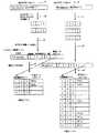
図6に示すように、メインヘッダはCOD(Coding style default)、QCD(Quantization default)の必須マーカセグメントとCOC(Coding style component)、QCC(Quantization component)、RGN(Region of interest)、POC(Progressive order change)、PPM(Packed packet headers、main header)、TLM(Tile-part length)、PLM(Packet length、main header)、CRG(Component registration)、COM(Comment)のオプションマーカセグメントで構成される。ここで、SIZマーカセグメントには、コンポーネント数とかタイルサイズなどの非圧縮時の画像の情報が記述され画像コンポーネントの幅と高さについての情報を含む。CODとCOCマーカセグメントは、圧縮されたデータはどの様に復号されるべきかを示すパラメータを含む。CODマーカにはプログレッション順序、レイヤ数、プレシンクトサイズ、デコンポジション分割数が記述されている。QCDマーカは量子化に係る情報が記載されている。またCOMマーカはコメント等の情報を付加したいときに利用するマーカで、メインヘッダ、タイルヘッダの双方で使用することが可能である。 As shown in FIG. 6, the main header includes COD (Coding style default), QCD (Quantization default) essential marker segments, COC (Coding style component), QCC (Quantization component), RGN (Region of interest), POC (Progressive order marker), PPM (Packed packet headers, main header), TLM (Tile-part length), PLM (Packet length, main header), CRG (Component registration), and COM (Comment) option marker segments. Here, the SIZ marker segment describes image information at the time of non-compression such as the number of components and tile size, and includes information about the width and height of the image component. The COD and COC marker segments contain parameters that indicate how the compressed data should be decoded. The COD marker describes the progression order, the number of layers, the precinct size, and the number of decomposition divisions. The QCD marker describes information relating to quantization. The COM marker is a marker used when adding information such as a comment, and can be used in both the main header and the tile header.
メインヘッダの後に、一連の“タイルパート”がある。各タイルパートは、特定のタイルと部分を識別する“SOT”マーカセグメントで始まる。各タイルパートについて符号化されたデータには、“SOT”マーカセグメントが先行する。“SOT”マーカセグメントには、タイルパート数に係る情報を含んでいる。
実際の符号データは、図7に示すように、SOT(Start of tile-part)マーカで始まり、タイルヘッダ、SOD(Start of data)マーカ、タイルデータ(符号)で構成される。これら画像全体に相当する符号データの後に、符号の終了を示すEOC(End of codestream)マーカが付加される。メインヘッダはCOD、QCDの必須マーカセグメントとCOC、QCC、RGN、POC、PPM、TLM、PLM、CRG、COMのオプションマーカセグメントで構成される。
図7は、JPEG2000のコード・ストリームの一例である。After the main header is a series of “tile parts”. Each tile part begins with a “SOT” marker segment that identifies the particular tile and part. The encoded data for each tile part is preceded by an “SOT” marker segment. The “SOT” marker segment includes information related to the number of tile parts.
As shown in FIG. 7, the actual code data starts with an SOT (Start of tile-part) marker, and includes a tile header, an SOD (Start of data) marker, and tile data (code). After the code data corresponding to the entire image, an EOC (End of codestream) marker indicating the end of the code is added. The main header is composed of COD and QCD essential marker segments and COC, QCC, RGN, POC, PPM, TLM, PLM, CRG and COM optional marker segments.
FIG. 7 shows an example of a JPEG2000 code stream.
図6の右端2つに、タイルヘッダ構成を示す。図6は、タイルデータの先頭に付加されるマーカセグメント列であり、COD、COC、QCD、QCC、RGN、POC、PPT、PLT、COMのマーカセグメントが使用可能である。
一方、図6の右下は、タイル内が複数に分割されている場合における分割されたタイルパートの先頭に付加されるマーカセグメント列であり、POC、PPT、PLT、COMのマーカセグメントが使用可能である。タイルヘッダでは必須マーカセグメントはなく、すべてオプションである。
タイルデータ(符号)は、連続したパケットで構成される。コード・ストリーム中のパケットの順番をプログレッション順序と呼んでいる。
以上のことから、JPEG2000コードフォーマットを分析することで、コンポーネント数、レイヤ数、プレシンクトサイズ、デコンポジション分割数などの階層符号データを構成する各階層のレベル数がわかる。また、プログレッション順序についても知ることができる。The tile header configuration is shown at two right ends in FIG. FIG. 6 shows a marker segment sequence added to the head of tile data. COD, COC, QCD, QCC, RGN, POC, PPT, PLT, and COM marker segments can be used.
On the other hand, the lower right of FIG. 6 is a marker segment sequence added to the head of the divided tile part when the tile is divided into a plurality of segments, and marker segments of POC, PPT, PLT, and COM can be used. It is. There is no mandatory marker segment in the tile header, all are optional.
Tile data (code) is composed of continuous packets. The order of packets in the code stream is called the progression order.
From the above, by analyzing the JPEG2000 code format, the number of levels of each layer constituting the hierarchical code data such as the number of components, the number of layers, the precinct size, the number of decomposition divisions, and the like can be known. You can also know the progression order.
次に、符号データを構成する断片的な符号列によって符号データの階層構造を推定する動作について説明する。
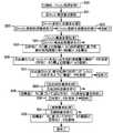
図8は、キャッシュ管理に係る処理フローチャートである。
図8に示すように、まず、クライアントからの処理要求待ちとなり(S1)、クライアントから復号出力処理の要求があると復号出力処理要求処理となり、出力要求ファイル名、又はファイル名と出力範囲とが指定される(S2)。次に、クライアント内のキャッシュ(あるいは外部記憶装置)の符号データ検査処理を行い(S3)、クライアントが要求した対象の符号データがある場合(S4)、対象の符号データを読み出し(S5)、復号化処理を行う(S6)。Next, an operation for estimating the hierarchical structure of code data by using a fragmented code string constituting the code data will be described.
FIG. 8 is a process flowchart relating to cache management.
As shown in FIG. 8, first, the client waits for a processing request from the client (S1). When there is a request for decryption output processing from the client, decryption output processing request processing is performed, and the output request file name or file name and output range are determined. Designated (S2). Next, code data check processing of the cache (or external storage device) in the client is performed (S3). When there is target code data requested by the client (S4), the target code data is read (S5) and decoded. (S6).
また、クライアントが要求した対象の符号データがキャッシュにない場合(S7)、サーバへ符号データのアップロード要求を行い、サーバからクライアントは要求した対象の符号データを受信し(S8)、新たにアップロードした符号データをキャッシュ又は外部記憶装置に保存し(S9)、復号化処理を行なって(S6)、出力処理を行う(S10)。
また、クライアントが要求した対象の符号データがキャッシュにあるが、符号データを構成する一部の符号列のみがキャッシュにないような場合がある。そのような場合、キャッシュに存在しない符号列のみを要求するのが一般的である。しかしながら、一部の符号データのみがキャッシュにないような場合であっても、全ての符号列が揃っていない場合には、全ての符号列のロードを要求する。If the target code data requested by the client is not in the cache (S7), a request for uploading the code data is made to the server, and the client receives the target code data requested from the server (S8) and newly uploads it. The code data is stored in a cache or an external storage device (S9), a decoding process is performed (S6), and an output process is performed (S10).
In addition, there is a case where the target code data requested by the client is in the cache, but only a part of the code string constituting the code data is not in the cache. In such a case, it is common to request only a code string that does not exist in the cache. However, even if only a part of the code data is not in the cache, if all the code strings are not complete, it is requested to load all the code strings.
次に、断片的な符号列(パケット)群よりの構造推定について説明する。
図9は、断片的な符号列(パケット)群より構造を把握する概念図である。
A.サーバからクライアントへ部分符号データを出力する。出力された部分符号データは階層化符号データであり、たとえば、前述したような、JPEG2000のコード・ストリームであったり、JPIPのストリームである。
B.クライアントは、部分符号データに含まれる符号列の階層レベルを符号列ごとに抽出する。先に述べたように、部分符号データがJPEG2000のコード・ストリームや、JPIPのストリームである場合は、それぞれストリームのデータを参照することによって算出できる。Next, structure estimation from a fragmented code string (packet) group will be described.
FIG. 9 is a conceptual diagram for grasping the structure from a fragmented code string (packet) group.
A. Partial code data is output from the server to the client. The output partial code data is layered code data, for example, a JPEG2000 code stream or a JPIP stream as described above.
B. The client extracts the hierarchical level of the code string included in the partial code data for each code string. As described above, when the partial code data is a JPEG2000 code stream or a JPIP stream, it can be calculated by referring to the stream data.
この図で示した例では、2つの符号列が抽出されており、ひとつの符号列は、第一階層がレベル2、第二階層がレベル1、第三階層がレベル1である。もうひとつの符号列は、第一階層がレベル2、第二階層がレベル1、第三階層がレベル2である。
C.上記部分符号データに含まれる符号列の階層レベルに基づき符号列の階層レベルを推定する。
D.クライアントが有するキャッシュデータ管理テーブルに符号列の最高階層レベルを書き込む。各階層ごと最高階層レベルをもつように階層データテーブルを作成する。次に符号列をキャッシュに保存し、その符号列へのポインタを書き込む。符号列へのポインタを記載している構造データの項目は、初期値がNULLであり、符号データがない列はNULLとなる。In the example shown in this figure, two code strings are extracted, and one code string is
C. The hierarchical level of the code string is estimated based on the hierarchical level of the code string included in the partial code data.
D. The highest hierarchical level of the code string is written in the cache data management table held by the client. A hierarchical data table is created so that each hierarchy has the highest hierarchical level. Next, the code string is stored in the cache, and a pointer to the code string is written. An item of structure data describing a pointer to a code string has an initial value of NULL, and a string having no code data is NULL.
続いて、E.新しい部分符号データをサーバからクライアントに出力する。
F.クライアントは、部分符号データに含まれる符号列の階層レベルを符号列ごとに抽出する。この例では、新たに新しい符号列が3つ受信した場合を示す。
G.同様に、部分符号データに含まれる符号列の階層レベルを使用して符号列の階層レベルを推定する。先に作成し書き込んだキャッシュデータ管理テーブルに記述してある各階層毎のレベルと比較して大きい場合は書き換える。この例では、第二階層の階層レベル3が大きな値であり3に書き換わっている。
H.同様に、キャッシュデータ管理テーブルへ符号列の最高階層レベルを書き込む。各階層ごと最高階層レベルをもつように階層データテーブルを作成する。
このような部分符号データに含まれる符号列から符号データの構造が推定できる。上に示したように、本推定方式によれば、構造情報の順次更新する機能を有する。Subsequently, E.I. New partial code data is output from the server to the client.
F. The client extracts the hierarchical level of the code string included in the partial code data for each code string. In this example, three new code strings are received.
G. Similarly, the hierarchical level of the code string is estimated using the hierarchical level of the code string included in the partial code data. If it is larger than the level of each hierarchy described in the cache data management table created and written earlier, it is rewritten. In this example, the
H. Similarly, the highest hierarchical level of the code string is written into the cache data management table. A hierarchical data table is created so that each hierarchy has the highest hierarchical level.
The structure of the code data can be estimated from the code string included in such partial code data. As shown above, according to the present estimation method, there is a function of sequentially updating the structure information.
図10は、キャッシュ更新生成処理概略フローチャートである。ここでは、符号データの構造を推定する部分を含んでおり、符号列の各階層ごとの階層レベルを調べ、その最大値を、符号データのその階層の階層レベルの最大値であると推定する。
図10に示すように、部分符号データに含まれる符号列の階層レベルを抽出し(S11)、キャッシュデータ管理テーブルへ符号列の最高階層レベルを書き込んだ(S12)後、構造テーブルの更新(S13)及び符号データの書き込みを行い(S14)、処理を終了する。FIG. 10 is a schematic flowchart of cache update generation processing. Here, a part for estimating the structure of the code data is included, the layer level for each layer of the code string is examined, and the maximum value is estimated to be the maximum value of the layer level of the layer of the code data.
As shown in FIG. 10, the hierarchical level of the code string included in the partial code data is extracted (S11), and the highest hierarchical level of the code string is written to the cache data management table (S12), and then the structure table is updated (S13). ) And code data are written (S14), and the process is terminated.
図3は、構造データ管理テーブルの構成例である。特徴的なところは、キャッシュの符号列を管理するために、キャッシュ管理部108には、符号データ解析部1010、管理テーブル構造テーブル生成処理部1011、同変更処理部1012、同参照処理部1013、符号データ保存処理部1014、を備えている。
符号データ解析部1010では、符号データを解析し、構造を推定するために必要な各符号列の情報(階層数と各階層ごとのその符号列の属するレベル)を抽出する。管理テーブル構造テーブル生成処理部1011では、図9で説明したように、各符号列の情報(部分符号データに含まれる符号列の階層レベル)に基づき管理テーブルと構造テーブルとを生成する。このとき、符号列は符号データ保存処理部1014で保存する。FIG. 3 is a configuration example of the structural data management table. Characteristically, in order to manage the code string of the cache, the
The code data analysis unit 1010 analyzes the code data and extracts information on each code string (the number of layers and the level to which the code string belongs for each layer) necessary for estimating the structure. As described with reference to FIG. 9, the management table structure table generation processing unit 1011 generates a management table and a structure table based on information of each code string (hierarchy level of the code string included in the partial code data). At this time, the code string is stored in the code data storage processing unit 1014.
図11は、キャッシュ管理処理フローチャートである。ここでは、キャッシュ更新生成要求処理1011、キャッシュ構造変更処理1012、追加保存要求処理1011、参照要求処理1013を含む。
図11に示すように、まず、クライアントによりキャッシュ管理処理が開始されると(S20)、キャッシュ管理要求解析が行われ(S21)、キャッシュ更新処理の要求があった場合(S22)、キャッシュ更新生成要求処理が行われて(S23)終了する。次に、キャッシュ構造変更の要求があったの場合(S24)、符号データの最上位階層レベルの使用頻度に基づき、最も使用頻度の多い階層レベルを算出し(S25)、キャッシュ又は外部記憶装置の構造データを変更し(S26)、復号処理の許容プログレッションに対応するように構造データを変更して(S27)、処理を終了する。次に、追加保存の要求があった場合(S28)、構造データに基づいて追加符号データの保存位置を特定し(S29)、符号データを保存して(S30)、処理を終了する。次に、参照要求があった場合(S31)、構造データに基づいて符号データの範囲の符号データを参照し(S32)、処理を終了する。FIG. 11 is a flowchart of cache management processing. Here, a cache update generation request process 1011, a cache structure change process 1012, an additional storage request process 1011, and a reference request process 1013 are included.
As shown in FIG. 11, first, when the cache management process is started by the client (S20), the cache management request analysis is performed (S21). When there is a request for the cache update process (S22), the cache update generation is performed. Request processing is performed (S23), and the process ends. Next, when there is a cache structure change request (S24), the most frequently used hierarchy level is calculated based on the use frequency of the highest hierarchy level of the code data (S25), and the cache or external storage device The structure data is changed (S26), the structure data is changed so as to correspond to the allowable progression of the decoding process (S27), and the process is terminated. Next, when there is a request for additional storage (S28), the storage position of the additional code data is specified based on the structure data (S29), the code data is stored (S30), and the process ends. Next, when there is a reference request (S31), reference is made to code data in the range of code data based on the structure data (S32), and the process is terminated.
次に、キャッシュデータの構造管理について説明する。
本発明の特徴の1つは、符号データの階層構造を推定し、キャッシュ管理テーブル、構造テーブルを生成することである。
図12は、キャッシュデータ(符号列構造)管理のためのデータ構造の基本構成図である。キャッシュデータ(符号列構造)管理のためのデータ構造は、管理テーブルと構造テーブルと符号列保存部よりなる。本実施例では、構造テーブルは表形成であるが、後述する別の実施例(図15)ではツリー構造をもっている。管理テーブルは、符号データ名(ファイル名)、階層数、各階層毎の階層レベル数(階層レベルの最大値)、構造データへのアドレス(ポインタ)により構成されている。階層数により階層レベル数の項目の数が変更される。
構造テーブルは、階層レベル数の各階層分の組み合わせの全ての項目を含む。符号列の属する各階層の階層レベルに該当する符号データへのポインタの部分に該符号列が保存されている。Next, the structure management of cache data will be described.
One of the features of the present invention is that a hierarchical structure of code data is estimated and a cache management table and a structure table are generated.
FIG. 12 is a basic configuration diagram of a data structure for managing cache data (code string structure). A data structure for managing cache data (code string structure) includes a management table, a structure table, and a code string storage unit. In this embodiment, the structure table is a table, but another embodiment (FIG. 15) described later has a tree structure. The management table includes a code data name (file name), the number of hierarchies, the number of hierarchy levels for each hierarchy (maximum value of hierarchy levels), and an address (pointer) to the structure data. The number of items of the hierarchy level number is changed depending on the hierarchy number.
The structure table includes all items of combinations of each hierarchy level number. The code string is stored in a pointer portion to code data corresponding to the hierarchical level of each hierarchy to which the code string belongs.
図13は、別のデータ構造の基本構成図である。管理テーブルとしてファイル(符号データ)が、サブファイル(サブ符号データ)により構成されるような場合である。
全体の文書画像に絵柄などの画像データが組み込んであるような構造化文書画像の符号化などで、符号データもこのような階層構造を持たせる場合がある。このような場合にあっては、キャッシュを管理するためのデータ構造も、本実施例のように、符号データの階層関係にしたがって管理テーブルも階層構造をもたせて実現する。それぞれのサブファイルが、それぞれ独立の構造テーブルをもたせることで、符号列間の関係(構造)が管理でき、構造化文書画像にも対応することができる。FIG. 13 is a basic configuration diagram of another data structure. This is a case where a file (code data) as a management table is composed of subfiles (subcode data).
Coded data may have such a hierarchical structure by coding a structured document image in which image data such as a picture is incorporated in the entire document image. In such a case, the data structure for managing the cache is also realized by providing the management table with a hierarchical structure according to the hierarchical relationship of the code data as in this embodiment. By providing each subfile with an independent structure table, the relationship (structure) between code strings can be managed, and a structured document image can also be handled.
図14は、キャッシュデータの構造化処理フローチャートである。
図14に示すように、まず、クライアントによりキャッシュデータの更新生成処理1が開始されると(S40)、対象符号データの符号列を順次取り出し(S41)、全ての符号列を終了すると(S42)、S43へ進む。次に、部分符号データに含む符号列の階層レベルを抽出し符号データの各階層の最高階層レベル番号を算出し(S43)、各階層の最高階層レベルを持つ全ての階層レベルの組み合わせパターンをもつ構造テーブルを作成する(S45)。次に、対象符号データの符号列を順次取り出し(S43)、全ての符号列終了し(S47)、該符号列を保存し(S48)、符号列の階層レベルを調べ、構造テーブルの該階層レベルの符号列へのポインタに符号列のアドレスを書込み(S49)、処理を終了する。
なお、キャッシュデータの更新生成処理の場合に、上記図12、図13などのデータ構造を生成し、キャッシュ上に符号列を順次保存する。すなわち、本発明の特徴の1つは、キャッシュに符号列を保存する前段階で前述した構造の推定をするところである。
このような処理により、推定機能により推定した階層構造に基づいて保存する階層符号データを構成する符号列(パケット)を管理する手段を提供することができる。FIG. 14 is a flowchart of the cache data structuring process.
As shown in FIG. 14, when the cache data
In the case of cache data update generation processing, the data structures shown in FIGS. 12 and 13 are generated, and the code strings are sequentially stored on the cache. That is, one of the features of the present invention is that the above-described structure estimation is performed before the code string is stored in the cache.
By such processing, it is possible to provide means for managing a code string (packet) constituting hierarchical code data to be stored based on the hierarchical structure estimated by the estimation function.
次に、キャッシュモデルのアクセス単位を階層符号データの階層単位とするデータ構造について説明する。
図15は、ツリー構造のキャッシュ管理テーブル、構造テーブルの基本構成図である。このツリー構造は、前述した図12、図13のテーブル構造とは互換性がある。すなわち、テーブル構造は、ツリー構造へ変換することも、逆も任意に変更することができる。ツリー構造をもつ構造テーブルは、階層ノードにより構成されている。各階層ノードは、階層レベルNoと下位階層レベルへの全てのポインタと情報項目より構成されている。最下位の階層では、各階層ノードは階層レベルNoと符号列へのポインタ格納領域をもっている。下位階層レベルへの全てのポインタはもっていない。また、符号列がない場合は、該ポインタ格納領域はNULLになっている。
本実施形態では、管理テーブルには、次の最上位の階層の階層ノードへのポインタをもっている。係る最上位の階層の階層ノードへのポインタをもつ特別な階層ノードを設け、管理テーブルがその特別な階層ノードへのポインタをもつような構成であってもかまわないが、本実施例の方が、符号列を参照する場合に特別な余分な階層ノードが存在しない分高速に実現できる。Next, a data structure in which an access unit of the cache model is a hierarchical unit of hierarchical code data will be described.
FIG. 15 is a basic configuration diagram of a tree-structured cache management table and structure table. This tree structure is compatible with the table structures shown in FIGS. That is, the table structure can be converted into a tree structure and vice versa. A structure table having a tree structure is composed of hierarchical nodes. Each hierarchical node includes a hierarchical level No, all pointers to lower hierarchical levels, and information items. In the lowest hierarchy, each hierarchy node has a hierarchy level number and a pointer storage area for a code string. Not all pointers to lower hierarchy levels. When there is no code string, the pointer storage area is NULL.
In the present embodiment, the management table has a pointer to the hierarchy node of the next highest hierarchy. There may be a configuration in which a special hierarchy node having a pointer to the hierarchy node of the highest hierarchy is provided, and the management table has a pointer to the special hierarchy node. When a code string is referred to, it can be realized at high speed because there is no special extra hierarchical node.
図16は、別のキャッシュデータの構造化処理フローチャートである。
図16に示すように、まず、クライアントによりキャッシュデータの更新生成処理2が開始されると(S50)、対象符号データの符号列を順次取り出し(S51)、全ての符号列を終了してS53へ進む。次に、部分符号データに含まれる符号列の階層レベルを抽出し符号データの各階層の最高階層レベル番号を算出し(S54)、各階層の最高階層レベルを持つ全ての階層レベルの組み合わせパターンをもつ構造テーブル作成する(S55)。
次に、構造テーブルへ符号列へのポインタの書き込みを行い(S53)、キャッシュデータ管理テーブル上の各階層のレベル数を読み込み(S53−1)、前記レベル数をもつ階層ノードデータを作成する(S53−2)。ここで、階層ノードデータは、(i)階層レベルNo、(ii)下位階層の階層ノードデータへのポインタ、(iii)下位階層データ有無フラグ項目よりなる)。FIG. 16 is a flowchart of another cache data structuring process.
As shown in FIG. 16, first, when
Next, a pointer to the code string is written to the structure table (S53), the number of levels of each hierarchy on the cache data management table is read (S53-1), and hierarchical node data having the level number is created (S53-1). S53-2). Here, the hierarchy node data includes (i) a hierarchy level number, (ii) a pointer to hierarchy node data of a lower hierarchy, and (iii) a lower hierarchy data presence / absence flag item).
次に、各階層ノードデータの(i)階層レベルNoを記載し(S53−3)、各階層ノードデータの(ii)下位階層の階層ノードデータへのポインタを記載する(S53−4)。この時、最下位階層ノードデータの(ii)下位階層の階層ノードデータへのポインタの初期値はNULLとしておく。また、(iii)下位階層データ有無フラグは0とする。
次に、保存対象とする符号列毎に順次以下の処理をする(S53−5)。
すなわち、符号列を保存し(S53−5−1)、階層ノードデータを上位階層から下位階層へと辿りながら、その符号列の各階層レベルで(i)階層レベルNoと一致する最下位の階層ノードデータを探し、該最下位の階層ノードデータの(ii)下位階層の階層ノードデータへのポインタ先を、符号列が保存されているアドレスとする(S53−5−2)。この時、上位階層の階層ノードデータから(ii)下位階層の階層ノードデータへのポインタ先を辿っていった時の階層レベルNoが、その符号の階層レベルであるようになっている。
次に、階層ノードデータを上位階層から下位階層へと辿りながら、該最下位の階層ノードデータの(ii)下位階層の階層ノードデータへのポインタを書き込む時に、辿られた階層ノードデータの(iii)下位階層データ有無フラグを+1する(S53−5−3)。Next, (i) the hierarchy level number of each hierarchy node data is described (S53-3), and (ii) a pointer to the hierarchy node data of the lower hierarchy of each hierarchy node data is described (S53-4). At this time, the initial value of the pointer to the hierarchy node data of (ii) lower hierarchy of the lowest hierarchy node data is set to NULL. Further, (iii) the lower layer data presence / absence flag is set to 0.
Next, the following processing is sequentially performed for each code string to be stored (S53-5).
That is, the code string is stored (S53-5-1), and the hierarchical node data is traced from the upper hierarchy to the lower hierarchy, and at each hierarchical level of the code string, (i) the lowest hierarchy that matches the hierarchical level No. The node data is searched, and the pointer destination to the hierarchy node data of (ii) lower hierarchy of the lowest hierarchy node data is set as the address where the code string is stored (S53-5-2). At this time, the hierarchical level No when the pointer destination from the hierarchical node data of the upper hierarchy to (ii) the hierarchical node data of the lower hierarchy is the hierarchical level of the code.
Next, when tracing the hierarchy node data from the upper hierarchy to the lower hierarchy and writing a pointer to the hierarchy node data of (ii) lower hierarchy of the lowest hierarchy node data, (iii) ) The lower layer data presence / absence flag is incremented by 1 (S53-5-3).
図16のキャッシュデータの生成処理において、図15に記載のツリー構造をもつ構造テーブルを生成する処理例を示す。各階層ノードは、情報項目をもつが、図15では、下位階層の符号列の有無を示す。符号列を保存するときに、その符号列の属する階層レベルにあたる階層ノードの同項目の値をカウントアップすることによって生成する。各階層毎にそれ以下の階層に符号データを有するかどうかを判別する識別子を使用することによって、構造データを辿ることで上位階層を調べるだけで、それ以下の階層に符号データがないことが判別できるので、階層構造データで参照される符号データの高速な参照が容易にできる。階層構造データの効率的な参照が可能となる。 16 shows an example of processing for generating a structure table having the tree structure shown in FIG. 15 in the cache data generation processing of FIG. Each hierarchical node has an information item, but FIG. 15 shows the presence or absence of a lower-level code string. When the code string is stored, the code string is generated by counting up the value of the same item of the hierarchy node corresponding to the hierarchy level to which the code string belongs. By using an identifier that determines whether each layer has code data in a lower layer, it is determined that there is no code data in the lower layer by simply examining the upper layer by following the structure data. Therefore, high-speed reference of the code data referred to by the hierarchical structure data can be facilitated. Efficient reference of hierarchical structure data becomes possible.
ところで、図15あるいは、図12、図13で示した構造データを使用することによって、ある階層レベルに属する符号列を参照することは容易である。符号列に対応してそれの属する階層レベルを知ることが容易であり、かつ、階層毎に階層レベルによって体系化された形式で保存されているからである。例えば、最上位階層の階層レベルが1である符号データは、符号データに対応した同階層の階層レベルが1である符号列を探せばよいが、図12、図13のテーブルタイプの構造データにおいては、連続的に並んでいるため参照は高速にできる。一方、図15の構造データにおいては、階層ノードの該当する階層の階層レベル番号が1である階層ノードから下位階層ノードへのポインタをたどっていくことで該符号列を参照できる。
このような構造データの調整により、保存される符号化データの符号列の制御単位を部分符号データのアクセス単位とすることができる。部分符号データのアクセス効率を高められる。
また、要求している符号データの中に、クライアントのキャッシュ上にない符号列が存在する場合には、欠落符号列の再送を要求する。By the way, it is easy to refer to a code string belonging to a certain hierarchical level by using the structure data shown in FIG. 15, FIG. 12, or FIG. This is because it is easy to know the hierarchical level to which the code string belongs and is stored in a format organized by hierarchical level for each hierarchy. For example, code data with the highest hierarchy level of 1 may be searched for a code string corresponding to code data with the same hierarchy level of 1 in the table type structure data of FIGS. Can be referred to at high speed because they are continuously arranged. On the other hand, in the structure data of FIG. 15, the code string can be referred to by following a pointer from a hierarchical node having a hierarchical level number of 1 corresponding to the hierarchical node to a lower hierarchical node.
By such adjustment of the structure data, the control unit of the code string of the encoded data to be stored can be set as the access unit of the partial code data. Access efficiency of partial code data can be increased.
Further, if there is a code string that is not in the client's cache in the requested code data, a retransmission of the missing code string is requested.
次に、欠落符号列の処理について説明する。
図17は、図15記載のツリー構造をもつ構造テーブルを解析して、欠落符号列を判別処理する処理フローチャートである。このようにして、階層符号化された符号データの部分符号データの中で欠けている符号列を算出できる。
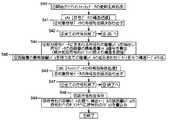
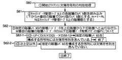
図17に示すように、まず、クライアントにより欠落符号列の判別処理が開始されると(S60)、キャッシュデータ管理テーブル上の各階層のレベル数を読み込む(S61)。ここで、下からm番目の階層でD(m)個のレベル数とし、m=1〜Nとし、Nはキャッシュデータ管理テーブル上の階層数とする。Next, processing of missing code strings will be described.
FIG. 17 is a processing flowchart for analyzing the structure table having the tree structure shown in FIG. 15 and determining missing code strings. In this way, it is possible to calculate a missing code string in the partial code data of the hierarchically encoded code data.
As shown in FIG. 17, when the missing code string discrimination process is started by the client (S60), the number of levels in each hierarchy on the cache data management table is read (S61). Here, the number of D (m) levels in the mth hierarchy from the bottom is set, m = 1 to N, and N is the number of levels on the cache data management table.
次に、指定の階層レベルSの階層ノードデータを上位階層から下位階層へと辿りながら(S62)、M番目の階層の階層ノードデータの(iii)下位階層データ有無フラグの値Pについて、P<D(1)×D(2)…×D(M−1)で(S62−1)、指定の階層レベルSを構成する符号列には欠落符号列を含んでいる場合は、終了し、それ以外の場合は、指定の階層レベルSを構成する符号列には欠落符号列を含んでいない(S62−2)。
なお、サーバクライアントシステムにおいては、例えば、クライアントは、サーバから、階層符号データの部分符号データを受信し、上記手段によって受信された部分符号データの欠落符号列を算出し、前記欠落符号列を含む部分符号データを受信する。Next, while tracing the hierarchical node data of the specified hierarchical level S from the upper hierarchy to the lower hierarchy (S62), the value P of the (iii) lower hierarchy data presence flag of the Mth hierarchy node data is P < If D (1) × D (2)... × D (M−1) (S62-1) and the code sequence constituting the specified hierarchical level S includes a missing code sequence, the process ends. In other cases, the code string constituting the specified hierarchical level S does not include a missing code string (S62-2).
In the server client system, for example, the client receives the partial code data of the hierarchical code data from the server, calculates the missing code string of the partial code data received by the above means, and includes the missing code string The partial code data is received.
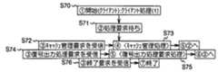
図18は、キャッシュ管理に係る処理フローチャートである。
図18に示すように、まず、クライアントによりキャッシュ管理に係る処理が開始されると(S70)、処理要求待ちとなり(S71)、キャッシュ管理要求を受信すると(S72)、キャッシュ管理処理へ移り(S73)、復号出力処理要求を受信すると(S74)、復号出力処理要求処理へ移り(S75)、終了要求を受信すると(S76)、終了する。
ところで、先に説明したように、本発明の構造データを使用して符号列を参照する実施例においては、特定の階層のあるレベルを構成符号列を特定することが容易に実現でき、上記欠落符号列を含むかどうかの判定方法を使用して、特定の階層の符号データが全て揃っている(キャッシュ上にある)かどうかの判別が容易にできる。そこで、クライアントは、特定の階層の符号データが全て揃っていない場合にその符号列を全てロードすることもできる。まとめて使用される可能性の高い符号列を入手する手段を提供し、利用価値を高められる。
ところで、クライアントにおける欠落符号列のロードは、使用者からの部分符号データのロード要求時だけで実行するに限らず、処理のバックグラウンドで実行することもできる。FIG. 18 is a process flowchart relating to cache management.
As shown in FIG. 18, first, when processing related to cache management is started by the client (S70), the processing request is waited (S71), and when a cache management request is received (S72), the processing proceeds to cache management processing (S73). When the decryption output process request is received (S74), the process proceeds to the decryption output process request process (S75). When the end request is received (S76), the process ends.
By the way, as described above, in the embodiment in which the code string is referred to by using the structure data of the present invention, it is easy to specify the constituent code string at a certain level of the specific hierarchy, and the above missing Using the method for determining whether or not a code string is included, it is possible to easily determine whether or not all the code data of a specific layer is prepared (on the cache). Therefore, the client can also load all of the code strings when not all of the code data of a specific layer is available. A means for obtaining code strings that are likely to be used together is provided, and the utility value can be increased.
Incidentally, the loading of the missing code string in the client is not limited to being performed only when the partial code data is requested to be loaded from the user, but can also be performed in the background of the processing.
図19は、バックグランドキャッシュ処理フローチャートである。
図19に示すように、まず、クライアントによりバックグランドキャッシュ処理が開始されると(S80)、処理要求待ちとなり(S81)、復号出力処理要求を受信すると(S82)、復号出力処理要求処理となり(S83)、終了要求を受信すると(S84)、終了する。
次に、キャッシュ構造変更処理要求がなされると(S85)、欠落符号列の把握がなされ(S86)、欠落符号列を含む部分符号データをアップロードし(S87)、追加保存要求処理要求がなされる(S88)。
次に、キャッシュデータの構造の入れ替え制御について説明する。
階層符号データのプログレッションの使用頻度を利用することで、階層毎の重要度を推定する。一般に使用者は、階層符号データを使用する場合にあって、重要な階層要素を上位レベルの階層とするプログレッションをもつ符号データを使用する場合が多いことに基づく。本発明の一実施例では、階層毎の重要度に合わせて本発明のキャッシュデータの構造データを最頻度のプログレッションをもつように置き換えておくことで、参照頻度の高い部分符号データのロード要求の処理が実現できる。効率的なキャッシュ管理を実現する。FIG. 19 is a flowchart of background cache processing.
As shown in FIG. 19, first, when the background cache processing is started by the client (S80), the processing request is waited (S81), and when the decryption output processing request is received (S82), the decryption output processing request processing is performed ( When an end request is received (S84), the process ends.
Next, when a cache structure change process request is made (S85), a missing code string is grasped (S86), partial code data including the missing code string is uploaded (S87), and an additional storage request process request is made. (S88).
Next, cache data structure replacement control will be described.
The importance for each layer is estimated by using the use frequency of the progression of the hierarchical code data. In general, the user uses hierarchical code data, and often uses code data having a progression in which an important hierarchical element is a higher-level hierarchy. In one embodiment of the present invention, the structure data of the cache data of the present invention is replaced so as to have the most frequent progression according to the importance of each hierarchy, so that the load request of partial code data having a high reference frequency can be performed. Processing can be realized. Realize efficient cache management.
図20は、使用頻度により階層レベルの重要度によってキャッシュ管理する場合のクライアントサーバシステムの構成例を示す図である。キャッシュ管理部108に階層別使用頻度設定処理部1015があることが特徴的である。階層別使用頻度設定処理部1015では、高頻度に使用されている符号データのプログレッションを反映して、符号データの階層毎の重要順を設定している。
図21に示すように、管理テーブルに階層毎の重要度データを保存している。階層毎の重要順は、使用頻度等重要度によって設定する。
図11の処理フローでは、階層毎の使用頻度によって、必要であれば、構造データの変更を加えキャッシュ上の符号列の参照範囲を調整する。使用時の階層の重要性に基づいて符号データをロードする手段を提供する。FIG. 20 is a diagram illustrating a configuration example of a client server system in a case where cache management is performed according to the importance of the hierarchy level depending on the usage frequency. It is characteristic that the
As shown in FIG. 21, importance level data for each hierarchy is stored in the management table. The order of importance for each layer is set according to importance such as usage frequency.
In the processing flow of FIG. 11, if necessary, the structural data is changed and the reference range of the code string on the cache is adjusted according to the usage frequency for each layer. A means for loading code data based on the importance of the hierarchy in use is provided.
図22は、キャッシュ上の符号データのプログレッションオーダの変更をする方法を説明するための概念図である。構造テーブルしては、図12で説明したテーブルタイプのものを示すが、図15で示したツリータイプのものであっても同様である。互いに相互変換可能であるからである。構造テーブルの入れ替えとしては、階層レベルNoの記載された行の値によって列単位の順番を入れ替えることで実現する。すなわち、最上位の階層の階層レベル順に列単位のデータを並びかえ、続いて、次の階層の階層レベル順を上位階層のレベル順が損なわないように並び替え、続いて、同様な並び替えを下階層の階層レベルまで繰り返して処理する。
ところで、別実施形態として、階層構造化して保存した階層符号データを管理するか、階層構造化しないで保存した階層符号データを管理するかを、階層符号データの使用頻度により制御することもできる。FIG. 22 is a conceptual diagram for explaining a method of changing the progression order of code data on the cache. As the structure table, the table type shown in FIG. 12 is shown, but the structure table is the same as that of the tree type shown in FIG. This is because mutual conversion is possible. The replacement of the structure table is realized by changing the order of the column unit according to the value of the row in which the hierarchy level No is described. In other words, the data in units of columns is rearranged in the order of the hierarchical level of the highest hierarchy, and then the hierarchical level order of the next hierarchy is rearranged so that the level order of the upper hierarchy is not impaired, and then the same rearrangement is performed. Iterates to the lower hierarchy level.
By the way, as another embodiment, whether to manage hierarchical code data stored in a hierarchical structure or to manage hierarchical code data stored in a non-hierarchical structure can be controlled by the use frequency of the hierarchical code data.
図20では、階層別使用頻度設定処理部1015で、符号データのプログレッションオーダの使用頻度を算出することを説明したが、同時に、階層符号データであるかないかの使用頻度を集計することによって、簡単に実現できる。階層符号データが使用される頻度が多い場合にのみ本発明の保存符号データ構造を階層構造化して制御することで、処理パフォーマンスを高めることができる。
以上、キャッシュデータに存在しない符号データの送信要求をする応用実施例を中心に説明したが、本発明の構造データを使用することによって符号列の順番を簡単に置き換えることができるため、デコーダで許されるプログレッションオーダになるように符号列の順番を調整することもできる。In FIG. 20, it has been described that the use frequency setting processing unit 1015 for each layer calculates the use frequency of the progression order of the code data. Can be realized. The processing performance can be improved by controlling the storage code data structure of the present invention in a hierarchical structure only when the hierarchical code data is frequently used.
As described above, the application embodiment that requests transmission of code data that does not exist in the cache data has been mainly described. However, since the order of the code strings can be easily replaced by using the structure data of the present invention, it is permitted by the decoder. It is also possible to adjust the order of the code strings so as to be in the progression order.
101…クライアント、102…サーバ、103…キャッシュ、106…キャッシュモデル、108…キャッシュ管理部、110…要求、111…応答、201、202…クライアント、203…サーバ、250…ネットワーク、1010…符号データ解析部、1011…キャッシュ更新生成要求処理、1011…管理テーブル構造テーブル生成処理部、1011…追加保存要求処理、1012…キャッシュ構造変更処理、1012…同変更処理部、1013…参照要求処理、1013…同参照処理部、1014…符号データ保存処理部、1015…階層別使用頻度設定処理部 DESCRIPTION OF
Claims (6)
Translated fromJapanese前記部分符号データに含まれる符号列が、タイル、コンポーネント、位置、及び解像度を階層として、該階層のどのレベルのデータであるかを符号列毎に抽出する抽出手段と、
前記抽出手段で抽出した符号列毎の階層レベルに基づき、符号列毎の階層レベルを推定する階層レベル推定手段と、
前記推定手段で推定した符号列毎の最高階層レベルを管理テーブルに書き込む書込手段と、
前記推定手段で推定した最高階層レベルを、各階層ごとに最高階層レベルをもつように階層データテーブルを作成する作成手段と、
を有し、
前記書込手段は、
前記管理テーブルに記述してある各階層毎のレベルと、新たに受信した部分符号データに含まれる符号列毎の階層レベルとを比較し、前記管理テーブルに書き込まれている符号列毎の階層レベルより前記新たに受信した部分符号データに含まれる符号列毎の各階層レベルが大きい場合、前記新たに受信した部分符号データに含まれる符号列毎の階層レベルを前記管理テーブルに書き換えることを特徴とする画像処理装置。An image processing apparatus for loading partial code data via a communication line,
Extraction means for extracting, for each code string, acode string included in the partial code data,which is a level of data in the hierarchy, with a tile, component, position, and resolution as a hierarchy ;
Hierarchy level estimation means for estimating the hierarchy level for each code string based on the hierarchy level for each code string extracted by the extraction means;
Writing means for writing the highest hierarchical level for each code string estimated by the estimating means to the management table;
Creating means for creating a hierarchical data table so that the highest hierarchical level estimated by the estimating means has the highest hierarchical level for each hierarchy;
Have
The writing means includes
Comparing the level for each layer described in the management table with the layer level for each code string included in the newly received partial code data, the layer level for each code string written in the management table When each hierarchical level for each code string included in the newly received partial code data is larger, the hierarchical level for each code string included in the newly received partial code data is rewritten in the management table. An image processing apparatus.
前記JPEG2000のコード・ストリーム又はJPIPのストリームである場合は、夫々のストリームを参照することで階層レベルを算出することを特徴とする請求項2に記載の画像処理装置。The hierarchy level extracting means includes:
3. The image processing apparatus according to claim 2, wherein in the case of the JPEG 2000 code stream or JPIP stream, the hierarchical level is calculated by referring to each stream.
前記部分符号データに含まれる符号列が、タイル、コンポーネント、位置、及び解像度を階層として、該階層のどのレベルのデータであるかを符号列毎に抽出する抽出工程と、
前記抽出手段で抽出した符号列毎の階層レベルに基づき、符号列毎の階層レベルを推定する推定工程と、
前記推定工程で推定した符号列毎の最高階層レベルを管理テーブルに書き込む書込手段と、
前記推定工程で推定した最高階層レベルを、各階層ごとに最高階層レベルをもつように階層データテーブルを作成する作成工程と、
を有し、
前記書込工程は、
前記管理テーブルに記述してある各階層毎のレベルと、新たに受信した部分符号データに含まれる符号列毎の階層レベルとを比較し、前記管理テーブルに書き込まれている符号列毎の階層レベルより前記新たに受信した部分符号データに含まれる符号列毎の各階層レベルが大きい場合、前記新たに受信した部分符号データに含まれる符号列毎の階層レベルを前記管理テーブルに書き換えることを特徴とする画像処理方法。An image processing method for loading partial code data via a communication line,
An extraction step of extracting, for each code sequence, acode sequence included in the partial code data,which is a level of data in the hierarchy, with tiles, components, positions, and resolutions as layers
An estimation step for estimating a hierarchy level for each code string based on the hierarchy level for each code string extracted by the extraction unit;
Writing means for writing the highest hierarchical level for each code string estimated in the estimation step into a management table;
Creating the hierarchical data table so that the highest hierarchical level estimated in the estimating step has the highest hierarchical level for each hierarchy;
Have
The writing step includes
Comparing the level for each layer described in the management table with the layer level for each code string included in the newly received partial code data, the layer level for each code string written in the management table When each hierarchical level for each code string included in the newly received partial code data is larger, the hierarchical level for each code string included in the newly received partial code data is rewritten in the management table. Image processing method.
前記JPEG2000のコード・ストリーム又はJPIPのストリームである場合は、夫々のストリームを参照することで階層レベルを算出することを特徴とする請求項5に記載の画像処理方法。The extraction step includes
6. The image processing method according to claim 5, wherein in the case of the JPEG2000 code stream or JPIP stream, the hierarchical level is calculated by referring to each stream.
Priority Applications (2)
| Application Number | Priority Date | Filing Date | Title |
|---|---|---|---|
| JP2006217563AJP4716949B2 (en) | 2005-09-02 | 2006-08-09 | Image processing apparatus and image processing method |
| US11/515,163US7729549B2 (en) | 2005-09-02 | 2006-09-01 | Image processing apparatus and image processing method |
Applications Claiming Priority (3)
| Application Number | Priority Date | Filing Date | Title |
|---|---|---|---|
| JP2005255759 | 2005-09-02 | ||
| JP2005255759 | 2005-09-02 | ||
| JP2006217563AJP4716949B2 (en) | 2005-09-02 | 2006-08-09 | Image processing apparatus and image processing method |
Publications (2)
| Publication Number | Publication Date |
|---|---|
| JP2007097147A JP2007097147A (en) | 2007-04-12 |
| JP4716949B2true JP4716949B2 (en) | 2011-07-06 |
Family
ID=37829162
Family Applications (1)
| Application Number | Title | Priority Date | Filing Date |
|---|---|---|---|
| JP2006217563AExpired - Fee RelatedJP4716949B2 (en) | 2005-09-02 | 2006-08-09 | Image processing apparatus and image processing method |
Country Status (2)
| Country | Link |
|---|---|
| US (1) | US7729549B2 (en) |
| JP (1) | JP4716949B2 (en) |
Families Citing this family (14)
| Publication number | Priority date | Publication date | Assignee | Title |
|---|---|---|---|---|
| JP5162939B2 (en)* | 2007-03-30 | 2013-03-13 | ソニー株式会社 | Information processing apparatus and method, and program |
| JP2008258994A (en)* | 2007-04-06 | 2008-10-23 | Ricoh Co Ltd | Image processing device |
| MX2009010926A (en) | 2007-04-11 | 2009-12-01 | Red Com Inc | Video camera. |
| US8237830B2 (en) | 2007-04-11 | 2012-08-07 | Red.Com, Inc. | Video camera |
| JP5151561B2 (en)* | 2008-03-04 | 2013-02-27 | 株式会社リコー | Cache device |
| JP5061306B2 (en)* | 2008-03-31 | 2012-10-31 | Kddi株式会社 | Client device, server device, and volume data transmission system |
| JP5695080B2 (en) | 2009-12-16 | 2015-04-01 | レッド.コム,インコーポレイテッド | Resolution-based format for compressed image data |
| WO2014127153A1 (en) | 2013-02-14 | 2014-08-21 | Red. Com, Inc. | Video camera |
| US9244832B1 (en)* | 2013-03-15 | 2016-01-26 | Emc Corporation | Cache learning model |
| CN105659609A (en) | 2013-11-01 | 2016-06-08 | 索尼公司 | Image processing device and method |
| US10271076B2 (en)* | 2014-06-30 | 2019-04-23 | Sony Corporation | File generation device and method, and content playback device and method |
| EP3541079B1 (en) | 2014-06-30 | 2021-06-16 | Sony Corporation | Information processing device and method |
| US9794574B2 (en)* | 2016-01-11 | 2017-10-17 | Google Inc. | Adaptive tile data size coding for video and image compression |
| EP3649783B8 (en) | 2017-07-05 | 2025-04-09 | RED Digital Cinema, Inc. | Video image data processing in electronic devices |
Family Cites Families (13)
| Publication number | Priority date | Publication date | Assignee | Title |
|---|---|---|---|---|
| SE513353C2 (en)* | 1998-10-21 | 2000-08-28 | Ericsson Telefon Ab L M | Partial image retrieval in the compressed domain |
| JP3768934B2 (en) | 2001-08-30 | 2006-04-19 | キヤノン株式会社 | Image processing apparatus and data cache method thereof |
| JP3768866B2 (en) | 2001-11-29 | 2006-04-19 | キヤノン株式会社 | Method and apparatus for creating encoded data |
| US7324695B2 (en)* | 2002-03-18 | 2008-01-29 | Seimens Medical Solutions Usa, Inc. | Prioritized image visualization from scalable compressed data |
| JP4065535B2 (en) | 2002-12-09 | 2008-03-26 | キヤノン株式会社 | Code data creation method and apparatus |
| JP4125186B2 (en) | 2003-06-20 | 2008-07-30 | キヤノン株式会社 | Image processing method and image processing apparatus |
| US7711834B2 (en)* | 2002-12-13 | 2010-05-04 | Ricoh Co., Ltd. | Network access to partial document images |
| US7447369B2 (en)* | 2003-03-07 | 2008-11-04 | Ricoh Co., Ltd. | Communication of compressed digital images |
| US7460724B2 (en) | 2003-03-07 | 2008-12-02 | Ricoh Co., Ltd. | JPP-stream to JPEG 2000 codestream conversion |
| JP2005012685A (en)* | 2003-06-20 | 2005-01-13 | Canon Inc | Image processing method and image processing apparatus |
| US7200277B2 (en)* | 2003-07-01 | 2007-04-03 | Eastman Kodak Company | Method for transcoding a JPEG2000 compressed image |
| JP4416611B2 (en)* | 2003-10-01 | 2010-02-17 | キヤノン株式会社 | Image processing method and image processing apparatus |
| JP4371982B2 (en)* | 2004-11-08 | 2009-11-25 | キヤノン株式会社 | Image processing apparatus, control method therefor, computer program, and computer-readable storage medium |
- 2006
- 2006-08-09JPJP2006217563Apatent/JP4716949B2/ennot_activeExpired - Fee Related
- 2006-09-01USUS11/515,163patent/US7729549B2/ennot_activeExpired - Fee Related
Also Published As
| Publication number | Publication date |
|---|---|
| US7729549B2 (en) | 2010-06-01 |
| JP2007097147A (en) | 2007-04-12 |
| US20070051817A1 (en) | 2007-03-08 |
Similar Documents
| Publication | Publication Date | Title |
|---|---|---|
| JP4716949B2 (en) | Image processing apparatus and image processing method | |
| JP4709493B2 (en) | Method and product for communicating compressed digital images | |
| US7571382B2 (en) | Partial retrieval of images in the compressed domain | |
| US7697767B2 (en) | Code processing device, code processing method, program, and recording medium | |
| JP2004274758A (en) | Method and apparatus for converting jpp-stream into jpeg-2000 code stream | |
| JP2004524730A (en) | Video scalable compression method and apparatus | |
| JP2003023630A (en) | Image processing for JPEG2000 in server client environment | |
| JP4898513B2 (en) | Client / server system | |
| JP4349816B2 (en) | Image processing apparatus, image compression apparatus, image processing method, image compression method, program, and recording medium | |
| JP4834917B2 (en) | Image encoding apparatus and image server apparatus | |
| JP2004274759A (en) | Method and apparatus for communicating compressed digital images with limited access and server / client handover | |
| US20040213472A1 (en) | Image compression apparatus, image decompression apparatus, image compression method, image decompression method, program, and recording medium | |
| JP5515758B2 (en) | Image processing apparatus and method | |
| JP4151963B2 (en) | Image server device, client device, moving image distribution method, program, and information recording medium | |
| US7721971B2 (en) | Image processing system, image processing method and computer readable information recording medium | |
| US7409095B2 (en) | Image processing apparatus and method for scalable encoded image data | |
| JP2005123856A (en) | Image processing system, image processing method, program, and information recording medium | |
| JP4609918B2 (en) | Image processing system, image processing method, program, and information recording medium | |
| JP4773770B2 (en) | Image processing system, image processing method, program, and recording medium | |
| JP4073333B2 (en) | Image compression apparatus and image compression method | |
| JP3914197B2 (en) | Information processing apparatus, information processing method, program, and computer-readable recording medium | |
| JP4059399B2 (en) | Image processing apparatus, image processing system, image output control method, program, and recording medium | |
| JP5053528B2 (en) | Image processing apparatus, image processing system, image processing method, program, and recording medium | |
| JP4129913B2 (en) | Image processing apparatus and image processing method | |
| JP2007166013A (en) | Image processing method, image processing method, image processing program, and recording medium recording image processing program |
Legal Events
| Date | Code | Title | Description |
|---|---|---|---|
| A621 | Written request for application examination | Free format text:JAPANESE INTERMEDIATE CODE: A621 Effective date:20090423 | |
| A131 | Notification of reasons for refusal | Free format text:JAPANESE INTERMEDIATE CODE: A131 Effective date:20110125 | |
| A521 | Request for written amendment filed | Free format text:JAPANESE INTERMEDIATE CODE: A523 Effective date:20110210 | |
| A01 | Written decision to grant a patent or to grant a registration (utility model) | Free format text:JAPANESE INTERMEDIATE CODE: A01 Effective date:20110308 | |
| A61 | First payment of annual fees (during grant procedure) | Free format text:JAPANESE INTERMEDIATE CODE: A61 Effective date:20110329 | |
| R150 | Certificate of patent or registration of utility model | Free format text:JAPANESE INTERMEDIATE CODE: R150 | |
| FPAY | Renewal fee payment (event date is renewal date of database) | Free format text:PAYMENT UNTIL: 20140408 Year of fee payment:3 | |
| LAPS | Cancellation because of no payment of annual fees |