JP4715874B2 - Wireless power transmission system, power transmission device, and rectenna base station - Google Patents
Wireless power transmission system, power transmission device, and rectenna base stationDownload PDFInfo
- Publication number
- JP4715874B2 JP4715874B2JP2008161472AJP2008161472AJP4715874B2JP 4715874 B2JP4715874 B2JP 4715874B2JP 2008161472 AJP2008161472 AJP 2008161472AJP 2008161472 AJP2008161472 AJP 2008161472AJP 4715874 B2JP4715874 B2JP 4715874B2
- Authority
- JP
- Japan
- Prior art keywords
- power transmission
- pilot signal
- phase
- rectenna
- base station
- Prior art date
- Legal status (The legal status is an assumption and is not a legal conclusion. Google has not performed a legal analysis and makes no representation as to the accuracy of the status listed.)
- Active
Links
Images


Classifications
- H—ELECTRICITY
- H01—ELECTRIC ELEMENTS
- H01Q—ANTENNAS, i.e. RADIO AERIALS
- H01Q3/00—Arrangements for changing or varying the orientation or the shape of the directional pattern of the waves radiated from an antenna or antenna system
- H01Q3/26—Arrangements for changing or varying the orientation or the shape of the directional pattern of the waves radiated from an antenna or antenna system varying the relative phase or relative amplitude of energisation between two or more active radiating elements; varying the distribution of energy across a radiating aperture
- H01Q3/2605—Array of radiating elements provided with a feedback control over the element weights, e.g. adaptive arrays
- B—PERFORMING OPERATIONS; TRANSPORTING
- B64—AIRCRAFT; AVIATION; COSMONAUTICS
- B64G—COSMONAUTICS; VEHICLES OR EQUIPMENT THEREFOR
- B64G1/00—Cosmonautic vehicles
- B64G1/22—Parts of, or equipment specially adapted for fitting in or to, cosmonautic vehicles
- B64G1/42—Arrangements or adaptations of power supply systems
- B64G1/428—Power distribution and management
- B64G1/4282—Power distribution and management for transmitting power to earth or other spacecraft
- B—PERFORMING OPERATIONS; TRANSPORTING
- B64—AIRCRAFT; AVIATION; COSMONAUTICS
- B64G—COSMONAUTICS; VEHICLES OR EQUIPMENT THEREFOR
- B64G1/00—Cosmonautic vehicles
- B64G1/22—Parts of, or equipment specially adapted for fitting in or to, cosmonautic vehicles
- B64G1/66—Arrangements or adaptations of apparatus or instruments, not otherwise provided for
- H—ELECTRICITY
- H01—ELECTRIC ELEMENTS
- H01Q—ANTENNAS, i.e. RADIO AERIALS
- H01Q1/00—Details of, or arrangements associated with, antennas
- H01Q1/12—Supports; Mounting means
- H01Q1/22—Supports; Mounting means by structural association with other equipment or articles
- H01Q1/24—Supports; Mounting means by structural association with other equipment or articles with receiving set
- H01Q1/248—Supports; Mounting means by structural association with other equipment or articles with receiving set provided with an AC/DC converting device, e.g. rectennas
- H—ELECTRICITY
- H02—GENERATION; CONVERSION OR DISTRIBUTION OF ELECTRIC POWER
- H02J—CIRCUIT ARRANGEMENTS OR SYSTEMS FOR SUPPLYING OR DISTRIBUTING ELECTRIC POWER; SYSTEMS FOR STORING ELECTRIC ENERGY
- H02J50/00—Circuit arrangements or systems for wireless supply or distribution of electric power
- H02J50/20—Circuit arrangements or systems for wireless supply or distribution of electric power using microwaves or radio frequency waves
- H02J50/27—Circuit arrangements or systems for wireless supply or distribution of electric power using microwaves or radio frequency waves characterised by the type of receiving antennas, e.g. rectennas
- H—ELECTRICITY
- H02—GENERATION; CONVERSION OR DISTRIBUTION OF ELECTRIC POWER
- H02J—CIRCUIT ARRANGEMENTS OR SYSTEMS FOR SUPPLYING OR DISTRIBUTING ELECTRIC POWER; SYSTEMS FOR STORING ELECTRIC ENERGY
- H02J50/00—Circuit arrangements or systems for wireless supply or distribution of electric power
- H02J50/40—Circuit arrangements or systems for wireless supply or distribution of electric power using two or more transmitting or receiving devices
- B—PERFORMING OPERATIONS; TRANSPORTING
- B64—AIRCRAFT; AVIATION; COSMONAUTICS
- B64G—COSMONAUTICS; VEHICLES OR EQUIPMENT THEREFOR
- B64G1/00—Cosmonautic vehicles
- B64G1/22—Parts of, or equipment specially adapted for fitting in or to, cosmonautic vehicles
- B64G1/42—Arrangements or adaptations of power supply systems
- B64G1/44—Arrangements or adaptations of power supply systems using radiation, e.g. deployable solar arrays
- B64G1/443—Photovoltaic cell arrays
- Y—GENERAL TAGGING OF NEW TECHNOLOGICAL DEVELOPMENTS; GENERAL TAGGING OF CROSS-SECTIONAL TECHNOLOGIES SPANNING OVER SEVERAL SECTIONS OF THE IPC; TECHNICAL SUBJECTS COVERED BY FORMER USPC CROSS-REFERENCE ART COLLECTIONS [XRACs] AND DIGESTS
- Y10—TECHNICAL SUBJECTS COVERED BY FORMER USPC
- Y10S—TECHNICAL SUBJECTS COVERED BY FORMER USPC CROSS-REFERENCE ART COLLECTIONS [XRACs] AND DIGESTS
- Y10S136/00—Batteries: thermoelectric and photoelectric
- Y10S136/291—Applications
- Y10S136/292—Space - satellite
Landscapes
- Engineering & Computer Science (AREA)
- Remote Sensing (AREA)
- Power Engineering (AREA)
- Aviation & Aerospace Engineering (AREA)
- Computer Networks & Wireless Communication (AREA)
- Radio Relay Systems (AREA)
- Variable-Direction Aerials And Aerial Arrays (AREA)
- Radio Transmission System (AREA)
Description
Translated fromJapaneseこの発明は、太陽光を受けて光電変換し、得られた電力をもとに生成したマイクロ波を複数の送信装置から送信し、これを受信装置により受信して電力を生成する無線電力伝送システム、これに用いる電力送信装置及びレクテナ基地局に関するものである。 The present invention relates to a wireless power transmission system that receives sunlight and performs photoelectric conversion, transmits microwaves generated based on the obtained power from a plurality of transmitting devices, and receives the received power by receiving devices to generate power. The present invention relates to a power transmission apparatus and a rectenna base station used for this.
例えば、特許文献1には、宇宙空間の軌道上に配置された発電用の衛星から、地上の受信装置へマイクロ波による電力伝送を行う従来の無線電力伝送システムが記載されている。この従来の無線電力伝送システムでは、発電用の衛星において、レクテナ基地局から送信されるパイロット信号を受信し、レクテナ基地局に対してパイロット返信信号を送信するというものである。パイロット信号はスペクトル拡散変調がされており、各衛星ごとにパイロット信号を識別して基準位相を取り出す。一方、パイロット返信信号にもスペクロラム拡散変調が施され、レクテナ基地局において、各パイロット返信信号の位相情報を抽出して各発電用の衛星の位相遅延が求められ、この位相遅延をパイロット信号の位相に反映するフィードバック系を形成することによって、各発電用の衛星からのマイクロ波の位相を揃え、より大きな電力を得ようとするものである。 For example,
特許文献1に記載された従来の無線電力伝送システムによれば、地上のレクテナ基地局では、送信するパイロット信号の拡散変調を行い、受信したパイロット返信信号の逆拡散復調を行う回路と、逆拡散により得られた各衛星ごとのパイロット返信信号の位相を比較して、これを一致させるべくフィードバックする回路が必要となり、設備が増大するという問題点がある。また、軌道上の各衛星においても、パイロット信号を逆拡散復調し、パイロット返信信号を拡散変調して生成するための回路が必要となり、回路規模が増大するという問題点とともに、これらの回路を駆動するための電力が必要となり、光電変換によって生成された電力の一部がパイロット信号関係の回路によって消費され、全体の発電効率が低下するという問題点もあった。 According to the conventional wireless power transmission system described in
この発明は、上記のような問題点を解決するためになされたもので、回路規模の増大を招くことなく、より効率的に、各電力送信装置から送信されるマイクロ波がレクテナ基地局において受信される際の位相を揃えることのできる無線電力伝送システム、電力送信装置及びレクテナ基地局を得ることを目的とする。 The present invention has been made to solve the above-described problems, and more efficiently receives microwaves transmitted from each power transmission apparatus at a rectenna base station without causing an increase in circuit scale. An object of the present invention is to obtain a wireless power transmission system, a power transmission device, and a rectenna base station capable of aligning the phases when being performed.
請求項1の発明に係る無線電力伝送システムは、複数の電力送信装置からレクテナ基地局にマイクロ波を送信し、上記レクテナ基地局で受信して電力を生成する無線電力伝送システムにおいて、上記レクテナ基地局は、マイクロ波を受信するレクテナと、上記電力送信装置へパイロット信号を送信するパイロット信号送信アンテナと、上記レクテナにより受信した電力値が増大するように、上記電力送信装置の識別符号を指定して上記電力送信装置の位相を変更するコマンド信号を生成する位相監視制御部と、上記コマンド信号を上記パイロット信号に重畳する変調器とを具備し、上記電力送信装置は、マイクロ波を上記レクテナ基地局へ送信する複数の送信アンテナ素子と、この複数の送信アンテナ素子へ送信信号を分配する分配器と、上記パイロット信号を受信するパイロット信号受信アンテナと、このパイロット信号受信アンテナにより受信したパイロット信号の到来方向を検出する追尾受信機と、この追尾受信機により検出したパイロット信号の到来方向に、上記複数の送信アンテナ素子から送信するマイクロ波の方向が向くように位相調整を行うビーム駆動制御部と、上記追尾受信機により受信するパイロット信号から上記コマンド信号を再生する復調器と、再生した上記コマンド信号に基づいて、上記識別符号が記憶する識別符号と一致する場合に、上記分配器で分配する前の送信信号の位相変更を行う位相制御器とを具備したものである。A wireless power transmission system according to a first aspect of the present invention is a wireless power transmission system in which microwaves are transmitted from a plurality of power transmission apparatuses to a rectenna base station, and received by the rectenna base station to generate power. The station specifies a rectenna that receives microwaves, a pilot signal transmission antenna that transmits a pilot signal to the power transmission device, and an identification code of the power transmission device so that a power value received by the rectenna increases. A phase monitoring controller that generates a command signal for changing the phase of the power transmission device, and a modulator that superimposes the command signal on the pilot signal, and the power transmission device transmits a microwave to the rectenna base. a plurality of transmit antenna elements for transmitting to the station,a distributor for distributing a transmission signal to the plurality of transmit antenna elements, the upper A pilot signal receiving antenna for receiving a pilot signal, a tracking receiver for detecting the arrival direction of the pilot signal received by the pilot signal receiving antenna, and the plurality of transmissions in the arrival direction of the pilot signal detected by the tracking receiver Based on the beam drive control unit that adjusts the phase so that the direction of the microwave transmitted from the antenna element is directed, the demodulator that reproduces the command signal from the pilot signal received by the tracking receiver, and the reproduced command signal And a phase controller that changes the phaseof a transmission signal before being distributed by the distributor when the identification code matches the stored identification code.
請求項2の発明に係るレクテナ基地局は、複数の電力送信装置から送信されるマイクロ波を受信し合成して電力を生成するレクテナ基地局において、上記マイクロ波を受信するレクテナと、上記電力送信装置へパイロット信号を送信するパイロット信号送信アンテナと、上記レクテナにより受信した電力値が増大するように、上記電力送信装置の識別符号を指定して上記電力送信装置の位相を変更するコマンド信号を生成する位相監視制御部と、上記コマンド信号を上記パイロット信号に重畳する変調器とを備えたものである。A rectenna base station according to a second aspect of the present invention is a rectenna base station that receives and combines microwaves transmitted from a plurality of power transmission devices to generate power, and a rectenna that receives the microwaves, and the power transmission. A pilot signal transmitting antenna for transmitting a pilot signal to the device and a command signal for changing the phase of the power transmitting device by designating the identification code of the power transmitting device so that the power value received by the rectenna increases. And amodulator for superimposing the command signal on the pilot signal .
請求項3の発明に係る電力送信装置は、レクテナ基地局にマイクロ波を送信する電力送信装置において、上記マイクロ波を上記レクテナ基地局へ送信する複数の送信アンテナ素子と、この複数の送信アンテナ素子へ送信信号を分配する分配器と、上記レクテナ基地局からのパイロット信号を受信するパイロット信号受信アンテナと、このパイロット信号受信アンテナにより受信したパイロット信号の到来方向を検出する追尾受信機と、この追尾受信機により検出したパイロット信号の到来方向に、上記複数の送信アンテナ素子から送信するマイクロ波の方向が向くように位相調整を行うビーム駆動制御部と、上記追尾受信機により受信するパイロット信号から識別符号が指定された位相を変更するコマンド信号を再生する復調器と、再生したコマンド信号に基づき、上記識別符号が記憶する識別符号と一致する場合に、上記分配器で分配する前の送信信号の位相変更を行う位相制御器とを備えたことを特徴とする電力送信装置。
According to a third aspect of the present invention, there is provided a power transmission apparatus for transmitting microwaves to a rectenna base station, wherein the plurality of transmission antenna elements transmit the microwaves to the rectenna base station, and theplurality of transmission antenna elements. A distributor for distributing a transmission signal to the pilot signal, a pilot signal receiving antenna for receiving a pilot signal from the rectenna base station, a tracking receiver for detecting the arrival direction of the pilot signal received by the pilot signal receiving antenna, and the tracking Identification from the pilot signal received by the tracking receiver and the beam drive control unit that adjusts the phase so that the direction of the microwaves transmitted from the plurality of transmitting antenna elements is directed to the arrival direction of the pilot signal detected by the receiver A demodulator that reproduces a command signal that changes the phase specified by the code, and a reproduced Based on command signals, when the identification code matches the identification code to be stored, the power transmitting apparatus characterized by comprising a phase controller for performing phase change in thetransmit signal before distributing above the distributor.
請求項1乃至請求項3に記載の発明によれば、レクテナ基地局は、受信したマイクロ波の電力値が増大するように、電力送信装置の識別符号を指定して位相を変更するコマンド信号を生成し、パイロット信号に重畳して送信し、電力送信装置は、パイロット信号を受信してパイロット信号の到来方向に送信するマイクロ波の方向が向くように位相調整し、パイロット信号からコマンド信号を再生するので、電力送信装置側のコマンド受信系をパイロット信号の受信系を用いて構成することができ、回路規模の増大を抑制することができる。
According to the first to third aspects of the present invention, the rectenna base station sends a command signal for changing the phase by designating the identification code of the power transmission device so that the received microwave power value increases. Generate, superimpose on pilot signal and transmit, power transmission device receives pilot signal and adjusts phase so that direction of microwave to transmit in the arrival direction of pilot signal is directed, and reproduces command signal from pilot signal Therefore, the command reception system on the power transmission apparatus side can be configured using the pilot signal reception system, and an increase in circuit scale can be suppressed.
実施の形態1
この発明の実施の形態1に係る無線電力伝送システム、電力送信装置及びレクテナ基地局について図1乃至図6を用いて説明する。図1はこの発明の実施の形態1に係る無線電力伝送システムの構成図であり、図1(a)は離散的に配置される発電衛星に設けた電力送信装置からマイクロ波伝送するケースを、図1(b)は機械的に結合された複数の電力送信装置からマイクロ波伝送するケースを表わしている。尚、図1(b)における電力送信装置を含む送信側装置は、宇宙空間に配置されるものや、地球上や成層圏などに配置されるものなどが考えられる。図1(a)において、1は太陽光を受けて光電変換して電力を生成し、マイクロ波により送電する複数の発電衛星であり、2は各発電衛星に設けた電力送信装置である。3は各発電衛星1及び各電力送信装置2を統制する統制衛星であり、主として発電衛星1との間で制御信号及び応答信号の送受信を行って制御するとともに、各発電衛星1(及び電力送信装置2)へ基準信号を送信するものである。4は電力送信装置2からのマイクロ波を受信して電力を生成するレクテナ基地局であり、5は複数のマイクロ波受信アンテナからなるレクテナ、6は電力送信装置2へ向けてパイロット信号を送信するパイロット信号送信アンテナである。レクテナ5及びパイロット信号送信アンテナ6はレクテナ基地局4の一部をなす。図1(b)において、7は複数の電力送信装置2を結合する機械的構造体、8は複数の電力送信装置2を統制する統制部であり、統制部8は各電力送信装置2との間で制御信号及び応答信号の送受信を行って各電力送信装置2を制御するとともに、各電力送信装置2へ基準信号を供給している。 A wireless power transmission system, a power transmission device, and a rectenna base station according to
各電力送信装置2はそれぞれマイクロ波をレクテナ基地局4へ向けて送信し、レクテナ基地局4内のレクテナ5によりマイクロ波が受信され合成されるが、このレクテナ5による受信の際に位相が相互にずれていると、レクテナ基地局4で生成される電力は低下することとなる。このような位相のずれは、各電力送信装置2で生成するマイクロ波の基準となる基準信号の位相ずれや、各電力送信装置2(とくに送信パネル部分)の位置変化や姿勢変化を要因として発生する。図2は電力送信装置2の位置及び姿勢変化の例を示しており、図2(a)はn個の送信電力装置2がほぼ独立に運動して位置や姿勢が変化するケースであり、図1(a)に示した複数の発電衛星1を用いた場合に顕著に生じる可能性がある。図2(b)はn個の送信電力装置2が一体として位置変化を生じる場合であり、図1(b)に示した機械的構造体7がほぼ剛体とみなせる場合に顕著に生じる可能性がある。図2(c)はn個の送信電力装置2がその一部において位置や姿勢変化を生じる場合であり、図1(b)に示した機械的構造体7が剛体とはできず、柔軟構造物として形成される場合に顕著に生じる可能性がある。 Each
これらの図2(a)乃至図2(c)において、個々の送信電力装置2に生じている姿勢の変化を方位方向の角度変化θAZ、仰角方向の角度変化θELで表わし、位置の変化を1つの仮想平面Sからの距離ΔLで表わす。姿勢の変化(θAZ、θEL)が生じることによって、各電力送信装置2から送信されるマイクロ波の方向がレクテナ5の方向からずれるので、これを補正するためにパイロット信号が用いられる。即ち、各電力送信装置2はパイロット信号を受信して到来方向を求め、パイロット信号の到来方向へマイクロ波の送信方向が向くように制御される。また、位置の変化ΔLが生じることによって、各電力送信装置2から送信されるマイクロ波は各装置ごとにその変化ΔL分の位相ずれを生じることになる。この位置変化ΔLに起因して生じる位相ずれを補正するための装置構成について検討する必要が生じるものである。2 (a) to 2 (c), the change in posture occurring in each
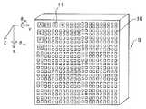
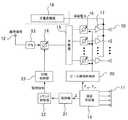
次に、この発明の実施の形態1に係る電力送信装置及びレクテナ基地局の構成を図3乃至図5に基づき説明する。図3は電力送信装置2の送信パネルの外形を示す外形図であり、9は基板、10はマイクロ波を送信する送信アンテナ素子、11はパイロット信号を受信するパイロット信号受信アンテナである。送信アンテナ素子10は基板9の面上にアレイ配置されており、基板に設けた給電線路によりマイクロ波給電されている。図4は電力送信装置2の構成を示す機能ブロック図である。図4において、12は統制衛星3又は統制部8から入力される基準信号の入力端子、13は基準信号を逓倍しキャリア信号を出力する逓倍器、14はキャリア信号の位相を調整する移相器、15はキャリア信号を分配する分配器、16は分配されたキャリア信号を位相調整する移相器、17はキャリア信号を増幅する増幅器である。18は光電変換部であり、光電変換部18にて生成した電力を増幅器17へ入力して所定の電力レベルのマイクロ波が生成され、増幅器17に接続された送信アンテナ素子10から空間へ放射される。増幅器17と送信アンテナ素子10との接続は、1対1に接続されていても良いし、1対4のように1個の増幅器17に対して複数個の送信アンテナ素子10が接続されるものでも良い。19はパイロット信号受信アンテナ11から得られる和信号及び差信号に基づきパイロット信号の到来方向(θAZ、θEL)を求める追尾受信機であり、20はパイロット信号の到来方向(θAZ、θEL)へ送信アンテナ素子10から送信するマイクロ波が向くように各移相器16の位相量を求め、求めた位相量により、各移相器16へ位相設定するビーム駆動制御部である。21は追尾受信機19により受信したパイロット信号の和信号からコマンド信号を復調する復調器、22は電力送信装置2に付された識別符号(この識別符号を自己の識別符号として記憶しているものとする。)と、復調器21により復調して検出されたコマンド信号に含まれる識別符号とを比較し、符号が一致している場合に、移相する指令(移相指令)を出力するコマンド判別器、23は、移相器14に対して位相設定する位相制御部である。Next, configurations of the power transmission apparatus and the rectenna base station according to
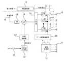
図5はレクテナ基地局の構成を示す機能ブロック図である。図5において、24はレクテナ5により受信したマイクロ波を整流して合成し電力生成する整流合成部であり、25はパイロット信号を生成し出力するパイロット信号送信部、26は電力値Pを監視し、各電力送信装置2の位相制御を行う位相監視制御部である。パイロット信号送信部25において、27は位相監視制御部26から出力されるコマンド信号(制御対象の電力送信装置2の識別符号を含む)によりパイロット信号の搬送波を変調する変調器、28はパイロット信号を増幅等してパイロット信号送信アンテナ6へ出力する送信機である。 FIG. 5 is a functional block diagram showing the configuration of the rectenna base station. In FIG. 5, 24 is a rectifying and synthesizing unit that rectifies and synthesizes the microwaves received by the
次に動作について説明する。レクテナ基地局4のパイロット信号送信アンテナ6から送信されたパイロット信号は、電力送信装置2のパイロット信号受信アンテナ11により受信される。図3にはパイロット信号受信アンテナ11の構成の一例が示されており、この例ではA乃至Gの7つのアンテナ素子により構成されている。いま、アンテナ素子A乃至Gで受信した信号をそれぞれSa乃至Sgとすると、追尾受信機19はパイロット受信アンテナ11により受信した信号を合成して、AZ方向の和信号Sa+Sb+Sc+Sd及び差信号Sa+Sb−Sc−Sdを、EL方向の和信号Sa+Se+Sf+Sg及び差信号Sa+Se−Sf−Sgを生成する。追尾受信機19は、パイロット信号のAZ方向及びEL方向が変化することにより、これらの和信号、差信号の値が変化する性質を利用して、パイロット信号の到来方向であるθAZとθELとを求め出力する。ビーム駆動制御部20はパイロット信号の到来方向である(θAZ、θEL)方向へマイクロ波送信するために、各移相器16に設定する位相量を算出し、移相器16に設定する。このような動作によって、図2(a)乃至図2(c)に示した位置及び姿勢の変化のうち、姿勢により生じるレクテナ基地局4のレクテナ5の方向と電力送信装置から送信するマイクロ波の方向とのずれが補正される。尚、パイロット信号受信アンテナ11の構成及び配置は、図3に示すものに限られるものではなく、上記のような追尾受信に利用できるものであればよい。Next, the operation will be described. The pilot signal transmitted from the pilot
次に図6に基づいて、図2(a)乃至図2(c)に示した位置変化ΔLによって生じる電力送信装置2間の位相ずれを補正する処理について説明する。図6は電力送信装置の位相調整を行う処理シーケンスを示すフローチャートであり、この処理は、レクテナ基地局4の位相監視制御部26によって行われる。いま、電力送信装置2はn台あるものとし、レクテナ基地局4内の位相監視制御部26は、まずステップS1において可変数kを1とし、ステップS2において可変数k=1に対応する1の電力送信装置2をその識別符号により指定する。ステップS3において、位相の変更を指令するコマンド信号(指定した識別符号を含む)をレクテナ基地局4から送信する。識別符号が一致する電力送信装置2は、コマンド信号に基づき、配下の送信パネル全体の位相を一律に所定量変更する。この変更によって、レクテナ基地局4のレクテナ5で受信される電力値Pが変化し、ステップS4において電力値Pを検出する。位相監視制御部26はステップS5で電力値Pが最大となるかの判定を行って、電力値Pが大きくなるように指定した電力送信装置2に対して、繰り返し位相の変更を指令するコマンド信号を送出する。ステップS5の判定により、電力値Pが最大となったところでk=1により指定した電力送信装置2の位相調整を終了し、可変数kがnよりも大きくなっていないことをステップS6により判定し、kを1増加して、次の電力送信装置2の位相調整に移る。これを順々に各電力送信装置ごとに繰り返して行っていくことにより、複数の電力送信装置2から送信されレクテナ5で受信されるマイクロ波の位相が揃い、生成する電力を最大若しくはこれに近い値にすることができる。 Next, processing for correcting a phase shift between the
なお、位相監視制御部26は、ステップS3乃至ステップS5における電力値Pが最大となる位相値を得るために、位相0度〜360度を所定角度ごとに変更させて各角度で電力値Pを検出しておき、最も大きくなる角度に位相を設定させるように指令する方法や、位相を変更する指令信号中に位相を変更する方向(プラス及びマイナス)を記述し、検出する電力値Pが大きくなる方向に電力送信装置の位相をステップ駆動せしめ、これ以上電力値Pが大きくならないところで指令を終了させる方法などがある。 The phase
図5に示したレクテナ基地局4は、位相監視制御部26が可変数kに対応する電力送信装置2の識別符号を指定し(ステップS2)、この識別符号を含むコマンド信号を変調器27へ出力することにより、変調器27においてパイロット信号にコマンド信号が重畳され、送信機28で増幅されて送信されることにより、ステップS3の「位相の変更を指令する」ことが実行される。図4に示す電力送信装置2は、パイロット信号受信アンテナ11により受信し追尾受信機19により合成された和信号を復調して、パイロット信号に重畳されたコマンド信号(含む識別符号)を再生し、コマンド判別器22は予め記憶している識別符号と比較して一致する場合に移相する指令を出力し、この指令を受けて位相制御部23は移相器14の位相を変更する。なお、コマンド信号は、コマンドコードと指定する電力送信装置の識別符号からなるが、専用コマンドである場合にはコマンドコードは無くてもよい。 In the
以上のように、レクテナ基地局4からの指令に基づいて次々と各電力送信装置2の位相を変更していき、レクテナ基地局4において電力値Pを検出しこれが大きくなるよう位相調整を行うことにより、図2(a)乃至図2(c)に示した位置変化ΔLに伴う、マイクロ波の位相ずれの補正ができるとともに、各電力送信装置2に供給される基準信号の位相についても内包されて、この位相調整によって補正されることになり、各電力送信装置2からの位相ずれが補正されてレクテナ基地局4において、より大きな電力を得ることができる。また、従来技術に開示されたような発電用の衛星側にパイロット返信信号を送信するための拡散変調器や送信機を持たせる必要がないので、回路規模の増大を抑えることができ、軽量化が図られるとともに装置の信頼性を向上することができる。また、パイロット信号にコマンド信号を重畳して送信することによって、電力送信装置側のコマンド信号の受信系をパイロット信号の受信系を用いて構成することができ、さらに回路規模の縮小化を図ることができる。 As described above, the phase of each
実施の形態2
この発明の実施の形態2に係る無線電力伝送システム、電力送信装置及びレクテナ基地局について図7を用いて説明する。この発明の実施の形態2に係る電力送信装置及びレクテナ基地局は、実施の形態1において図3乃至図5に基づき説明した構成、機能と同等な構成、機能を有している。ここでは、実施の形態2において相違する部分である電力送信装置の位相調整を行う処理シーケンスを図7に基づき説明する。 A wireless power transmission system, a power transmission device, and a rectenna base station according to
図7はこの発明の実施の形態2に係る電力送信装置の位相調整を行う処理シーケンスを示すフローチャートであり、この処理は、レクテナ基地局4の位相監視制御部26によって行われる。この処理フローにおいても、電力送信装置2はn台あるものとしている。レクテナ基地局4内の位相監視制御部26は、ステップS8においてレクテナ5により受信して得られる電力値Pを検出する。検出した電力値Pが下側しきい値P2より大きいかどうかをステップS9により判定する。電力値Pが下側しきい値P2より大きい場合には、許容範囲とみなしステップS8及びステップS9を繰り返す。検出した電力値Pが下側しきい値P2以下となるとステップS10に移行し位相調整を開始する。ステップS10からステップS16のシーケンスは実施の形態1において説明した図6におけるステップS1からステップS7のシーケンスと同じであり説明を省略するが、このステップS10からステップS16のシーケンスによって、n台の電力送信装置2の位相調整が順々に各電力送信装置ごとに繰り返して行われ、n台の電力送信装置2から送信されレクテナ5で受信されるマイクロ波の位相が揃い、生成する電力を最大若しくはこれに近い値にすることができる。n台の電力送信装置2の位相調整が終了するとステップS17に移行し、位相調整終了時に検出した電力値Pが上側しきい値P1よりも大きいかどうかを判定する。電力値Pが上側しきい値P1よりも大きい場合には、良好に位相調整ができたものと判断し、ステップS8に戻る。電力値Pが上側しきい値P1以下である場合には、再度、位相調整を行うようにステップS10に戻る。 FIG. 7 is a flowchart showing a processing sequence for adjusting the phase of the power transmission apparatus according to
上側しきい値P1と下側しきい値P2は構築するシステムの性能に応じて所定の値に設定することになる。各電力送信装置2が空間に放出するマイクロ波の電力は、図4に示した光電変換部18や増幅器17の効率、伝送線路における損失、送信パネルの指向性利得などを考慮して最大値を見積もることができ、さらに電力送信装置2から送信されたマイクロ波がレクテナ5で受信され合成される電力についても、位相が揃う条件により適切な解析を行うことにより理論最大値が求められる。この理論最大値に対して、各電力送信装置2での位相分解能や、マイクロ波送信方向のずれによる送信パネルの指向性利得の変化などの要因を考慮して能力値が求められる。例えば、この能力値を上側しきい値P1とし、システムに要求される最低発電能力値を下側しきい値P2に設定する。より具体的には各能力値を考慮して、例えば、合成電力の理論最大値に対して90%レベルを上側しきい値P1とし、80%レベルを下側しきい値P2とするような設定をしても良い。 The upper threshold value P1 and the lower threshold value P2 are set to predetermined values according to the performance of the system to be constructed. The power of the microwaves that each
また、上側しきい値P1及び下側しきい値P2は運用時に適切に再設定される構成としてもよい。実際の位相調整後の電力値Pの検出結果が複数回にわたって、ほぼ特定の値となるような場合には、その値が実ハードウェアの最大能力として把握されることになる。したがって、その特定の値を最大値とし、これに対して90%レベルを上側しきい値P1とし、80%レベルを下側しきい値P2と設定するようにしてもよい。 The upper threshold value P1 and the lower threshold value P2 may be appropriately reset during operation. When the detection result of the power value P after the actual phase adjustment is almost a specific value over a plurality of times, the value is grasped as the maximum capacity of the actual hardware. Therefore, the specific value may be set as the maximum value, and the 90% level may be set as the upper threshold value P1 and the 80% level may be set as the lower threshold value P2.
また、光電変換部18でモニタしている電力情報が電力送信装置2又は統制衛星3(或いは統制部8)から通信回線を用いてレクテナ基地局4へ提供される場合のレクテナ基地局4の構成の別の一例を図8に示す。この場合、レクテナ基地局4は電力情報を受信アンテナ29により受信し、テレメトリ受信機30により復調し再生して位相監視制御部26へ出力する。電力情報に基づいて位相監視制御部26はその時点で得られる電力最大値を知ることができ、上述の上側しきい値P1や下側しきい値P2を再設定するようにしてもよい。なお、図8において図5と同一の符号を付した回路及び部分は、図5におけるそれらの回路及び部分と同一又は相当する回路及び部分を表わす。 The configuration of the
実施の形態3
この発明の実施の形態3に係る無線電力伝送システム、電力送信装置及びレクテナ基地局について図9及び図10を用いて説明する。この発明の実施の形態3に係るレクテナ基地局は通信回線により位相の変更を指令するコマンド信号を送信するものであり、また電力送信装置2の電力情報を通信回線により取得するものである。図9はこの発明の実施の形態3に係るレクテナ基地局4の構成を示す機能ブロック図であり、図10はこの発明の実施の形態3に係る電力送信装置2の構成を示す機能ブロック図である。図9において31はコマンド信号を送信するコマンド送信機、32は送受分波器、33は通信回線送受信アンテナ、34はパイロット信号を送信するパイロット信号送信部である。図9において、図5と同一の符号を付した回路及び部分は、図5におけるそれらの回路及び部分と同一又は相当する回路及び部分を表わす。図10において、35はコマンド信号が入力される入力端子である。図10において、図4と同一の符号を付した回路及び部分は、図4におけるそれらの回路及び部分と同一又は相当する回路及び部分を表わす。 A wireless power transmission system, a power transmission device, and a rectenna base station according to
位相監視制御部26は、各電力送信装置2へ位相の変更を指令する信号を送信するが、これを通信回線により行ってもよい。この場合、レクテナ基地局4はコマンド送信機31を有し、位相監視制御部26から電力送信装置2の識別符号を含む位相変更の指令(コマンド信号)がコマンド送信機31へ入力されると、コマンド送信機31はこのコマンド信号を通信回線の搬送波に重畳し、送受分波器32及び送受信アンテナ33を介して、電力送信装置2又は統制衛星3(或いは統制部8)へ向けて送信する。電力送信装置2又は統制衛星3(或いは統制部8)はこれを受信し、コマンド信号を再生する。再生されたコマンド信号は入力端子35から入力され、コマンド判別器22により識別符号を比較し、一致する場合には移相指令が出力され、位相制御部23により移相器14の位相設定を行う。 The phase
また、光電変換部18でモニタしている電力情報が電力送信装置2又は統制衛星3(或いは統制部8)から通信回線を用いてレクテナ基地局4へ提供される。レクテナ基地局4は電力情報を送受信アンテナ33により受信し、送受分波器32を介してテレメトリ受信機30により復調し再生して位相監視制御部26へ出力する。電力情報に基づいて位相監視制御部26はその時点で得られる電力最大値を知ることができ、実施の形態2において説明した上側しきい値P1や下側しきい値P2を再設定するようにしてもよい。 Also, the power information monitored by the
2 電力送信装置
4 レクテナ基地局
5 レクテナ
6 パイロット信号送信アンテナ
10 送信アンテナ素子
11 パイロット信号受信アンテナ
14 移相器
16 移相器
19 追尾受信機
20 ビーム駆動制御部
21 復調器
22 コマンド判別器
23 位相制御部
24 整流合成部
25 パイロット信号送信部
26 位相監視制御部
27 変調器
29 受信アンテナ
30 テレメトリ受信機
31 コマンド送信機DESCRIPTION OF
Claims (3)
Translated fromJapanese上記レクテナ基地局は、マイクロ波を受信するレクテナと、上記電力送信装置へパイロット信号を送信するパイロット信号送信アンテナと、上記レクテナにより受信した電力値が増大するように、上記電力送信装置の識別符号を指定して上記電力送信装置の位相を変更するコマンド信号を生成する位相監視制御部と、上記コマンド信号を上記パイロット信号に重畳する変調器とを具備し、
上記電力送信装置は、マイクロ波を上記レクテナ基地局へ送信する複数の送信アンテナ素子と、この複数の送信アンテナ素子へ送信信号を分配する分配器と、上記パイロット信号を受信するパイロット信号受信アンテナと、このパイロット信号受信アンテナにより受信したパイロット信号の到来方向を検出する追尾受信機と、この追尾受信機により検出したパイロット信号の到来方向に、上記複数の送信アンテナ素子から送信するマイクロ波の方向が向くように位相調整を行うビーム駆動制御部と、上記追尾受信機により受信するパイロット信号から上記コマンド信号を再生する復調器と、再生した上記コマンド信号に基づいて、上記識別符号が記憶する識別符号と一致する場合に、上記分配器で分配する前の送信信号の位相変更を行う位相制御器とを具備したことを特徴とする無線電力伝送システム。In a wireless power transmission system that transmits microwaves to a rectenna base station from a plurality of power transmission devices and receives power at the rectenna base station to generate power,
The rectenna base station includes a rectenna that receives a microwave, a pilot signal transmission antenna that transmits a pilot signal to the power transmission device, and an identification code of the power transmission device so that a power value received by the rectenna increases. A phase monitoring control unit that generates a command signal that changes the phase of the power transmission device by designating, and a modulator that superimposes the command signal on the pilot signal,
The power transmission device includes a plurality of transmission antenna elements that transmit microwaves to the rectenna base station,a distributor that distributes transmission signals to the plurality of transmission antenna elements, and a pilot signal reception antenna that receives the pilot signals. The tracking receiver that detects the arrival direction of the pilot signal received by the pilot signal receiving antenna, and the direction of the microwaves transmitted from the plurality of transmitting antenna elements are in the arrival direction of the pilot signal detected by the tracking receiver. A beam drive control unit that adjusts the phase so as to face, a demodulator that reproduces the command signal from a pilot signal received by the tracking receiver, and an identification code that the identification code stores based on the reproduced command signal when matching the phase for phase change in thetransmit signal before distributing the above distributor Wireless power transmission system, characterized by comprising a control vessel.
Priority Applications (2)
| Application Number | Priority Date | Filing Date | Title |
|---|---|---|---|
| JP2008161472AJP4715874B2 (en) | 2008-06-20 | 2008-06-20 | Wireless power transmission system, power transmission device, and rectenna base station |
| US12/357,692US7888586B2 (en) | 2008-06-20 | 2009-01-22 | Wireless power transfer system, power transmitter, and rectenna base station |
Applications Claiming Priority (1)
| Application Number | Priority Date | Filing Date | Title |
|---|---|---|---|
| JP2008161472AJP4715874B2 (en) | 2008-06-20 | 2008-06-20 | Wireless power transmission system, power transmission device, and rectenna base station |
Publications (2)
| Publication Number | Publication Date |
|---|---|
| JP2010004324A JP2010004324A (en) | 2010-01-07 |
| JP4715874B2true JP4715874B2 (en) | 2011-07-06 |
Family
ID=41430489
Family Applications (1)
| Application Number | Title | Priority Date | Filing Date |
|---|---|---|---|
| JP2008161472AActiveJP4715874B2 (en) | 2008-06-20 | 2008-06-20 | Wireless power transmission system, power transmission device, and rectenna base station |
Country Status (2)
| Country | Link |
|---|---|
| US (1) | US7888586B2 (en) |
| JP (1) | JP4715874B2 (en) |
Cited By (2)
| Publication number | Priority date | Publication date | Assignee | Title |
|---|---|---|---|---|
| JP2011142708A (en)* | 2010-01-05 | 2011-07-21 | Mitsubishi Electric Corp | Wireless power transmission system, power transmission apparatus, and rectenna base station |
| KR20120134079A (en)* | 2011-05-31 | 2012-12-11 | 삼성전자주식회사 | Apparatus and method that divide wireless power in Wireless Resonant Power Transmission System |
Families Citing this family (215)
| Publication number | Priority date | Publication date | Assignee | Title |
|---|---|---|---|---|
| US11264841B2 (en) | 2007-06-14 | 2022-03-01 | Ossia Inc. | Wireless power transmission system |
| US8159364B2 (en)* | 2007-06-14 | 2012-04-17 | Omnilectric, Inc. | Wireless power transmission system |
| US8708901B2 (en)* | 2009-12-30 | 2014-04-29 | University Of Seoul Industry Cooperation Foundation | Health monitoring system with a waveguide to guide a wave from a power source |
| JP5161904B2 (en)* | 2010-02-22 | 2013-03-13 | 三菱重工業株式会社 | Phased array antenna and phase control method thereof |
| JP5578885B2 (en)* | 2010-02-26 | 2014-08-27 | 三菱重工業株式会社 | Phased array antenna and control method thereof |
| JP5310659B2 (en)* | 2010-06-29 | 2013-10-09 | 三菱電機株式会社 | Wireless power transmission system, rectenna base station, and power transmission apparatus |
| JP2012084971A (en)* | 2010-10-07 | 2012-04-26 | Ihi Aerospace Co Ltd | Phased-array antenna device |
| KR101743777B1 (en)* | 2010-10-21 | 2017-06-05 | 삼성전자주식회사 | Method for wireless charging and apparatus for the same |
| US9030161B2 (en) | 2011-06-27 | 2015-05-12 | Board Of Regents, The University Of Texas System | Wireless power transmission |
| US8797966B2 (en) | 2011-09-23 | 2014-08-05 | Ofinno Technologies, Llc | Channel state information transmission |
| US8885569B2 (en) | 2011-12-19 | 2014-11-11 | Ofinno Technologies, Llc | Beamforming signaling in a wireless network |
| JP5863455B2 (en)* | 2011-12-28 | 2016-02-16 | 三菱重工業株式会社 | Power receiving apparatus and wireless power transmission system |
| KR101953913B1 (en)* | 2012-04-02 | 2019-03-04 | 엘에스전선 주식회사 | Device and System for Wireless Power Transmission using Transmission Coil Array |
| US9847679B2 (en) | 2014-05-07 | 2017-12-19 | Energous Corporation | System and method for controlling communication between wireless power transmitter managers |
| US8306479B1 (en)* | 2012-07-06 | 2012-11-06 | Metropcs Wireless, Inc. | Polarization control for cell telecommunication system |
| US10148097B1 (en) | 2013-11-08 | 2018-12-04 | Energous Corporation | Systems and methods for using a predetermined number of communication channels of a wireless power transmitter to communicate with different wireless power receivers |
| US9893554B2 (en) | 2014-07-14 | 2018-02-13 | Energous Corporation | System and method for providing health safety in a wireless power transmission system |
| US9900057B2 (en) | 2012-07-06 | 2018-02-20 | Energous Corporation | Systems and methods for assigning groups of antenas of a wireless power transmitter to different wireless power receivers, and determining effective phases to use for wirelessly transmitting power using the assigned groups of antennas |
| US9887584B1 (en) | 2014-08-21 | 2018-02-06 | Energous Corporation | Systems and methods for a configuration web service to provide configuration of a wireless power transmitter within a wireless power transmission system |
| US10211680B2 (en) | 2013-07-19 | 2019-02-19 | Energous Corporation | Method for 3 dimensional pocket-forming |
| US10008889B2 (en) | 2014-08-21 | 2018-06-26 | Energous Corporation | Method for automatically testing the operational status of a wireless power receiver in a wireless power transmission system |
| US9871398B1 (en) | 2013-07-01 | 2018-01-16 | Energous Corporation | Hybrid charging method for wireless power transmission based on pocket-forming |
| US10211682B2 (en) | 2014-05-07 | 2019-02-19 | Energous Corporation | Systems and methods for controlling operation of a transmitter of a wireless power network based on user instructions received from an authenticated computing device powered or charged by a receiver of the wireless power network |
| US9954374B1 (en) | 2014-05-23 | 2018-04-24 | Energous Corporation | System and method for self-system analysis for detecting a fault in a wireless power transmission Network |
| US9838083B2 (en) | 2014-07-21 | 2017-12-05 | Energous Corporation | Systems and methods for communication with remote management systems |
| US9867062B1 (en) | 2014-07-21 | 2018-01-09 | Energous Corporation | System and methods for using a remote server to authorize a receiving device that has requested wireless power and to determine whether another receiving device should request wireless power in a wireless power transmission system |
| US9941707B1 (en) | 2013-07-19 | 2018-04-10 | Energous Corporation | Home base station for multiple room coverage with multiple transmitters |
| US9906065B2 (en) | 2012-07-06 | 2018-02-27 | Energous Corporation | Systems and methods of transmitting power transmission waves based on signals received at first and second subsets of a transmitter's antenna array |
| US10199835B2 (en) | 2015-12-29 | 2019-02-05 | Energous Corporation | Radar motion detection using stepped frequency in wireless power transmission system |
| US9843213B2 (en) | 2013-08-06 | 2017-12-12 | Energous Corporation | Social power sharing for mobile devices based on pocket-forming |
| US9859797B1 (en) | 2014-05-07 | 2018-01-02 | Energous Corporation | Synchronous rectifier design for wireless power receiver |
| US9252628B2 (en) | 2013-05-10 | 2016-02-02 | Energous Corporation | Laptop computer as a transmitter for wireless charging |
| US9991741B1 (en) | 2014-07-14 | 2018-06-05 | Energous Corporation | System for tracking and reporting status and usage information in a wireless power management system |
| US9787103B1 (en) | 2013-08-06 | 2017-10-10 | Energous Corporation | Systems and methods for wirelessly delivering power to electronic devices that are unable to communicate with a transmitter |
| US20150326070A1 (en) | 2014-05-07 | 2015-11-12 | Energous Corporation | Methods and Systems for Maximum Power Point Transfer in Receivers |
| US9143000B2 (en) | 2012-07-06 | 2015-09-22 | Energous Corporation | Portable wireless charging pad |
| US9859756B2 (en) | 2012-07-06 | 2018-01-02 | Energous Corporation | Transmittersand methods for adjusting wireless power transmission based on information from receivers |
| US10038337B1 (en) | 2013-09-16 | 2018-07-31 | Energous Corporation | Wireless power supply for rescue devices |
| US10193396B1 (en) | 2014-05-07 | 2019-01-29 | Energous Corporation | Cluster management of transmitters in a wireless power transmission system |
| US10224982B1 (en) | 2013-07-11 | 2019-03-05 | Energous Corporation | Wireless power transmitters for transmitting wireless power and tracking whether wireless power receivers are within authorized locations |
| US10992187B2 (en) | 2012-07-06 | 2021-04-27 | Energous Corporation | System and methods of using electromagnetic waves to wirelessly deliver power to electronic devices |
| US10199849B1 (en) | 2014-08-21 | 2019-02-05 | Energous Corporation | Method for automatically testing the operational status of a wireless power receiver in a wireless power transmission system |
| US9912199B2 (en) | 2012-07-06 | 2018-03-06 | Energous Corporation | Receivers for wireless power transmission |
| US9853458B1 (en) | 2014-05-07 | 2017-12-26 | Energous Corporation | Systems and methods for device and power receiver pairing |
| US10211674B1 (en) | 2013-06-12 | 2019-02-19 | Energous Corporation | Wireless charging using selected reflectors |
| US9923386B1 (en) | 2012-07-06 | 2018-03-20 | Energous Corporation | Systems and methods for wireless power transmission by modifying a number of antenna elements used to transmit power waves to a receiver |
| US10205239B1 (en) | 2014-05-07 | 2019-02-12 | Energous Corporation | Compact PIFA antenna |
| US9899873B2 (en) | 2014-05-23 | 2018-02-20 | Energous Corporation | System and method for generating a power receiver identifier in a wireless power network |
| US10223717B1 (en) | 2014-05-23 | 2019-03-05 | Energous Corporation | Systems and methods for payment-based authorization of wireless power transmission service |
| US9793758B2 (en) | 2014-05-23 | 2017-10-17 | Energous Corporation | Enhanced transmitter using frequency control for wireless power transmission |
| US10224758B2 (en) | 2013-05-10 | 2019-03-05 | Energous Corporation | Wireless powering of electronic devices with selective delivery range |
| US9438045B1 (en) | 2013-05-10 | 2016-09-06 | Energous Corporation | Methods and systems for maximum power point transfer in receivers |
| US9806564B2 (en) | 2014-05-07 | 2017-10-31 | Energous Corporation | Integrated rectifier and boost converter for wireless power transmission |
| US10230266B1 (en) | 2014-02-06 | 2019-03-12 | Energous Corporation | Wireless power receivers that communicate status data indicating wireless power transmission effectiveness with a transmitter using a built-in communications component of a mobile device, and methods of use thereof |
| US9124125B2 (en) | 2013-05-10 | 2015-09-01 | Energous Corporation | Wireless power transmission with selective range |
| US10124754B1 (en) | 2013-07-19 | 2018-11-13 | Energous Corporation | Wireless charging and powering of electronic sensors in a vehicle |
| US10075008B1 (en) | 2014-07-14 | 2018-09-11 | Energous Corporation | Systems and methods for manually adjusting when receiving electronic devices are scheduled to receive wirelessly delivered power from a wireless power transmitter in a wireless power network |
| US9847677B1 (en) | 2013-10-10 | 2017-12-19 | Energous Corporation | Wireless charging and powering of healthcare gadgets and sensors |
| US9948135B2 (en) | 2015-09-22 | 2018-04-17 | Energous Corporation | Systems and methods for identifying sensitive objects in a wireless charging transmission field |
| US9859757B1 (en)* | 2013-07-25 | 2018-01-02 | Energous Corporation | Antenna tile arrangements in electronic device enclosures |
| US9825674B1 (en) | 2014-05-23 | 2017-11-21 | Energous Corporation | Enhanced transmitter that selects configurations of antenna elements for performing wireless power transmission and receiving functions |
| US9939864B1 (en) | 2014-08-21 | 2018-04-10 | Energous Corporation | System and method to control a wireless power transmission system by configuration of wireless power transmission control parameters |
| US10186913B2 (en) | 2012-07-06 | 2019-01-22 | Energous Corporation | System and methods for pocket-forming based on constructive and destructive interferences to power one or more wireless power receivers using a wireless power transmitter including a plurality of antennas |
| US10381880B2 (en) | 2014-07-21 | 2019-08-13 | Energous Corporation | Integrated antenna structure arrays for wireless power transmission |
| US10270261B2 (en) | 2015-09-16 | 2019-04-23 | Energous Corporation | Systems and methods of object detection in wireless power charging systems |
| US9891669B2 (en) | 2014-08-21 | 2018-02-13 | Energous Corporation | Systems and methods for a configuration web service to provide configuration of a wireless power transmitter within a wireless power transmission system |
| US10063106B2 (en) | 2014-05-23 | 2018-08-28 | Energous Corporation | System and method for a self-system analysis in a wireless power transmission network |
| US10206185B2 (en) | 2013-05-10 | 2019-02-12 | Energous Corporation | System and methods for wireless power transmission to an electronic device in accordance with user-defined restrictions |
| US10291055B1 (en) | 2014-12-29 | 2019-05-14 | Energous Corporation | Systems and methods for controlling far-field wireless power transmission based on battery power levels of a receiving device |
| US9899861B1 (en) | 2013-10-10 | 2018-02-20 | Energous Corporation | Wireless charging methods and systems for game controllers, based on pocket-forming |
| US10256657B2 (en) | 2015-12-24 | 2019-04-09 | Energous Corporation | Antenna having coaxial structure for near field wireless power charging |
| US10050462B1 (en) | 2013-08-06 | 2018-08-14 | Energous Corporation | Social power sharing for mobile devices based on pocket-forming |
| US20150022008A1 (en)* | 2013-05-10 | 2015-01-22 | DvineWave Inc. | Home base station for multiple room coverage with multiple transmitters |
| US10141768B2 (en) | 2013-06-03 | 2018-11-27 | Energous Corporation | Systems and methods for maximizing wireless power transfer efficiency by instructing a user to change a receiver device's position |
| US9966765B1 (en) | 2013-06-25 | 2018-05-08 | Energous Corporation | Multi-mode transmitter |
| US9876394B1 (en) | 2014-05-07 | 2018-01-23 | Energous Corporation | Boost-charger-boost system for enhanced power delivery |
| US9887739B2 (en) | 2012-07-06 | 2018-02-06 | Energous Corporation | Systems and methods for wireless power transmission by comparing voltage levels associated with power waves transmitted by antennas of a plurality of antennas of a transmitter to determine appropriate phase adjustments for the power waves |
| US10103582B2 (en) | 2012-07-06 | 2018-10-16 | Energous Corporation | Transmitters for wireless power transmission |
| US9882430B1 (en) | 2014-05-07 | 2018-01-30 | Energous Corporation | Cluster management of transmitters in a wireless power transmission system |
| US10291066B1 (en) | 2014-05-07 | 2019-05-14 | Energous Corporation | Power transmission control systems and methods |
| US10128699B2 (en) | 2014-07-14 | 2018-11-13 | Energous Corporation | Systems and methods of providing wireless power using receiver device sensor inputs |
| US9853692B1 (en) | 2014-05-23 | 2017-12-26 | Energous Corporation | Systems and methods for wireless power transmission |
| US10063105B2 (en) | 2013-07-11 | 2018-08-28 | Energous Corporation | Proximity transmitters for wireless power charging systems |
| US9893768B2 (en) | 2012-07-06 | 2018-02-13 | Energous Corporation | Methodology for multiple pocket-forming |
| US10063064B1 (en) | 2014-05-23 | 2018-08-28 | Energous Corporation | System and method for generating a power receiver identifier in a wireless power network |
| US10090886B1 (en) | 2014-07-14 | 2018-10-02 | Energous Corporation | System and method for enabling automatic charging schedules in a wireless power network to one or more devices |
| US11502551B2 (en) | 2012-07-06 | 2022-11-15 | Energous Corporation | Wirelessly charging multiple wireless-power receivers using different subsets of an antenna array to focus energy at different locations |
| US9876648B2 (en) | 2014-08-21 | 2018-01-23 | Energous Corporation | System and method to control a wireless power transmission system by configuration of wireless power transmission control parameters |
| US10218227B2 (en) | 2014-05-07 | 2019-02-26 | Energous Corporation | Compact PIFA antenna |
| US10128693B2 (en) | 2014-07-14 | 2018-11-13 | Energous Corporation | System and method for providing health safety in a wireless power transmission system |
| US9368020B1 (en) | 2013-05-10 | 2016-06-14 | Energous Corporation | Off-premises alert system and method for wireless power receivers in a wireless power network |
| US10141791B2 (en) | 2014-05-07 | 2018-11-27 | Energous Corporation | Systems and methods for controlling communications during wireless transmission of power using application programming interfaces |
| US10263432B1 (en) | 2013-06-25 | 2019-04-16 | Energous Corporation | Multi-mode transmitter with an antenna array for delivering wireless power and providing Wi-Fi access |
| US9973021B2 (en) | 2012-07-06 | 2018-05-15 | Energous Corporation | Receivers for wireless power transmission |
| US10992185B2 (en) | 2012-07-06 | 2021-04-27 | Energous Corporation | Systems and methods of using electromagnetic waves to wirelessly deliver power to game controllers |
| US9812890B1 (en) | 2013-07-11 | 2017-11-07 | Energous Corporation | Portable wireless charging pad |
| US12057715B2 (en) | 2012-07-06 | 2024-08-06 | Energous Corporation | Systems and methods of wirelessly delivering power to a wireless-power receiver device in response to a change of orientation of the wireless-power receiver device |
| US20140008993A1 (en) | 2012-07-06 | 2014-01-09 | DvineWave Inc. | Methodology for pocket-forming |
| US9876379B1 (en) | 2013-07-11 | 2018-01-23 | Energous Corporation | Wireless charging and powering of electronic devices in a vehicle |
| US10439448B2 (en) | 2014-08-21 | 2019-10-08 | Energous Corporation | Systems and methods for automatically testing the communication between wireless power transmitter and wireless power receiver |
| US9941754B2 (en) | 2012-07-06 | 2018-04-10 | Energous Corporation | Wireless power transmission with selective range |
| US9893555B1 (en) | 2013-10-10 | 2018-02-13 | Energous Corporation | Wireless charging of tools using a toolbox transmitter |
| US10312715B2 (en) | 2015-09-16 | 2019-06-04 | Energous Corporation | Systems and methods for wireless power charging |
| US9843201B1 (en) | 2012-07-06 | 2017-12-12 | Energous Corporation | Wireless power transmitter that selects antenna sets for transmitting wireless power to a receiver based on location of the receiver, and methods of use thereof |
| US9941747B2 (en) | 2014-07-14 | 2018-04-10 | Energous Corporation | System and method for manually selecting and deselecting devices to charge in a wireless power network |
| US10243414B1 (en) | 2014-05-07 | 2019-03-26 | Energous Corporation | Wearable device with wireless power and payload receiver |
| US10965164B2 (en) | 2012-07-06 | 2021-03-30 | Energous Corporation | Systems and methods of wirelessly delivering power to a receiver device |
| US10090699B1 (en) | 2013-11-01 | 2018-10-02 | Energous Corporation | Wireless powered house |
| US9824815B2 (en) | 2013-05-10 | 2017-11-21 | Energous Corporation | Wireless charging and powering of healthcare gadgets and sensors |
| US9882427B2 (en) | 2013-05-10 | 2018-01-30 | Energous Corporation | Wireless power delivery using a base station to control operations of a plurality of wireless power transmitters |
| US9831718B2 (en) | 2013-07-25 | 2017-11-28 | Energous Corporation | TV with integrated wireless power transmitter |
| US9419443B2 (en) | 2013-05-10 | 2016-08-16 | Energous Corporation | Transducer sound arrangement for pocket-forming |
| US9537357B2 (en) | 2013-05-10 | 2017-01-03 | Energous Corporation | Wireless sound charging methods and systems for game controllers, based on pocket-forming |
| US9866279B2 (en) | 2013-05-10 | 2018-01-09 | Energous Corporation | Systems and methods for selecting which power transmitter should deliver wireless power to a receiving device in a wireless power delivery network |
| US9819230B2 (en) | 2014-05-07 | 2017-11-14 | Energous Corporation | Enhanced receiver for wireless power transmission |
| US9538382B2 (en) | 2013-05-10 | 2017-01-03 | Energous Corporation | System and method for smart registration of wireless power receivers in a wireless power network |
| US10103552B1 (en) | 2013-06-03 | 2018-10-16 | Energous Corporation | Protocols for authenticated wireless power transmission |
| US10003211B1 (en) | 2013-06-17 | 2018-06-19 | Energous Corporation | Battery life of portable electronic devices |
| US10021523B2 (en) | 2013-07-11 | 2018-07-10 | Energous Corporation | Proximity transmitters for wireless power charging systems |
| US9979440B1 (en) | 2013-07-25 | 2018-05-22 | Energous Corporation | Antenna tile arrangements configured to operate as one functional unit |
| US10075017B2 (en) | 2014-02-06 | 2018-09-11 | Energous Corporation | External or internal wireless power receiver with spaced-apart antenna elements for charging or powering mobile devices using wirelessly delivered power |
| US9935482B1 (en) | 2014-02-06 | 2018-04-03 | Energous Corporation | Wireless power transmitters that transmit at determined times based on power availability and consumption at a receiving mobile device |
| US10158257B2 (en) | 2014-05-01 | 2018-12-18 | Energous Corporation | System and methods for using sound waves to wirelessly deliver power to electronic devices |
| US9966784B2 (en) | 2014-06-03 | 2018-05-08 | Energous Corporation | Systems and methods for extending battery life of portable electronic devices charged by sound |
| US10153653B1 (en) | 2014-05-07 | 2018-12-11 | Energous Corporation | Systems and methods for using application programming interfaces to control communications between a transmitter and a receiver |
| US10153645B1 (en) | 2014-05-07 | 2018-12-11 | Energous Corporation | Systems and methods for designating a master power transmitter in a cluster of wireless power transmitters |
| US10170917B1 (en) | 2014-05-07 | 2019-01-01 | Energous Corporation | Systems and methods for managing and controlling a wireless power network by establishing time intervals during which receivers communicate with a transmitter |
| US9800172B1 (en) | 2014-05-07 | 2017-10-24 | Energous Corporation | Integrated rectifier and boost converter for boosting voltage received from wireless power transmission waves |
| US9973008B1 (en) | 2014-05-07 | 2018-05-15 | Energous Corporation | Wireless power receiver with boost converters directly coupled to a storage element |
| US9876536B1 (en) | 2014-05-23 | 2018-01-23 | Energous Corporation | Systems and methods for assigning groups of antennas to transmit wireless power to different wireless power receivers |
| US9871301B2 (en) | 2014-07-21 | 2018-01-16 | Energous Corporation | Integrated miniature PIFA with artificial magnetic conductor metamaterials |
| US10068703B1 (en) | 2014-07-21 | 2018-09-04 | Energous Corporation | Integrated miniature PIFA with artificial magnetic conductor metamaterials |
| US10116143B1 (en) | 2014-07-21 | 2018-10-30 | Energous Corporation | Integrated antenna arrays for wireless power transmission |
| JP6746573B2 (en)* | 2014-07-23 | 2020-08-26 | デイヴィッド ハイランド | System and method for collecting and distributing space-based solar energy |
| US9965009B1 (en) | 2014-08-21 | 2018-05-08 | Energous Corporation | Systems and methods for assigning a power receiver to individual power transmitters based on location of the power receiver |
| US9917477B1 (en) | 2014-08-21 | 2018-03-13 | Energous Corporation | Systems and methods for automatically testing the communication between power transmitter and wireless receiver |
| US9815573B2 (en)* | 2014-09-01 | 2017-11-14 | James Joshua Woods | Solar energy conversion and transmission system and method |
| EP3213390A4 (en)* | 2014-10-31 | 2018-03-14 | Teslonix Inc. | Wireless energy transfer using alignment of electromagnetic waves |
| US10474852B2 (en) | 2014-10-31 | 2019-11-12 | Teslonix Inc. | Charging long-range radio frequency identification tags |
| US10530190B2 (en) | 2014-10-31 | 2020-01-07 | Teslonix Inc. | Wireless energy transfer in a multipath environment |
| US10256678B2 (en) | 2014-10-31 | 2019-04-09 | Teslonix Inc. | Wireless energy transfer using alignment of electromagnetic waves |
| US10122415B2 (en) | 2014-12-27 | 2018-11-06 | Energous Corporation | Systems and methods for assigning a set of antennas of a wireless power transmitter to a wireless power receiver based on a location of the wireless power receiver |
| US9893535B2 (en) | 2015-02-13 | 2018-02-13 | Energous Corporation | Systems and methods for determining optimal charging positions to maximize efficiency of power received from wirelessly delivered sound wave energy |
| US10825417B2 (en) | 2015-04-10 | 2020-11-03 | Ossia Inc. | Wirelessly powered electronic display apparatuses |
| US10243412B1 (en) | 2015-08-27 | 2019-03-26 | The United States Of America As Represented By The Administrator Of The National Aeronautics And Space Administration | Beamforming rectennas, systems and methods for wireless power transfer |
| US10523033B2 (en) | 2015-09-15 | 2019-12-31 | Energous Corporation | Receiver devices configured to determine location within a transmission field |
| US12283828B2 (en) | 2015-09-15 | 2025-04-22 | Energous Corporation | Receiver devices configured to determine location within a transmission field |
| US9906275B2 (en) | 2015-09-15 | 2018-02-27 | Energous Corporation | Identifying receivers in a wireless charging transmission field |
| US10186893B2 (en) | 2015-09-16 | 2019-01-22 | Energous Corporation | Systems and methods for real time or near real time wireless communications between a wireless power transmitter and a wireless power receiver |
| US9871387B1 (en) | 2015-09-16 | 2018-01-16 | Energous Corporation | Systems and methods of object detection using one or more video cameras in wireless power charging systems |
| US10211685B2 (en) | 2015-09-16 | 2019-02-19 | Energous Corporation | Systems and methods for real or near real time wireless communications between a wireless power transmitter and a wireless power receiver |
| US9893538B1 (en) | 2015-09-16 | 2018-02-13 | Energous Corporation | Systems and methods of object detection in wireless power charging systems |
| US10158259B1 (en) | 2015-09-16 | 2018-12-18 | Energous Corporation | Systems and methods for identifying receivers in a transmission field by transmitting exploratory power waves towards different segments of a transmission field |
| US10778041B2 (en) | 2015-09-16 | 2020-09-15 | Energous Corporation | Systems and methods for generating power waves in a wireless power transmission system |
| US11710321B2 (en) | 2015-09-16 | 2023-07-25 | Energous Corporation | Systems and methods of object detection in wireless power charging systems |
| US9941752B2 (en) | 2015-09-16 | 2018-04-10 | Energous Corporation | Systems and methods of object detection in wireless power charging systems |
| US10008875B1 (en) | 2015-09-16 | 2018-06-26 | Energous Corporation | Wireless power transmitter configured to transmit power waves to a predicted location of a moving wireless power receiver |
| US10199850B2 (en) | 2015-09-16 | 2019-02-05 | Energous Corporation | Systems and methods for wirelessly transmitting power from a transmitter to a receiver by determining refined locations of the receiver in a segmented transmission field associated with the transmitter |
| US10135295B2 (en) | 2015-09-22 | 2018-11-20 | Energous Corporation | Systems and methods for nullifying energy levels for wireless power transmission waves |
| US10020678B1 (en) | 2015-09-22 | 2018-07-10 | Energous Corporation | Systems and methods for selecting antennas to generate and transmit power transmission waves |
| US10050470B1 (en) | 2015-09-22 | 2018-08-14 | Energous Corporation | Wireless power transmission device having antennas oriented in three dimensions |
| US10128686B1 (en) | 2015-09-22 | 2018-11-13 | Energous Corporation | Systems and methods for identifying receiver locations using sensor technologies |
| US10027168B2 (en) | 2015-09-22 | 2018-07-17 | Energous Corporation | Systems and methods for generating and transmitting wireless power transmission waves using antennas having a spacing that is selected by the transmitter |
| US10135294B1 (en) | 2015-09-22 | 2018-11-20 | Energous Corporation | Systems and methods for preconfiguring transmission devices for power wave transmissions based on location data of one or more receivers |
| US10033222B1 (en) | 2015-09-22 | 2018-07-24 | Energous Corporation | Systems and methods for determining and generating a waveform for wireless power transmission waves |
| US10153660B1 (en) | 2015-09-22 | 2018-12-11 | Energous Corporation | Systems and methods for preconfiguring sensor data for wireless charging systems |
| JP6486256B2 (en)* | 2015-10-09 | 2019-03-20 | 三菱電機株式会社 | Wireless power transmission apparatus and wireless power transmission system |
| US10333332B1 (en) | 2015-10-13 | 2019-06-25 | Energous Corporation | Cross-polarized dipole antenna |
| US10734717B2 (en) | 2015-10-13 | 2020-08-04 | Energous Corporation | 3D ceramic mold antenna |
| US9788282B2 (en) | 2015-11-30 | 2017-10-10 | Veniam, Inc. | Systems and methods for improving fixed access point coverage in a network of moving things |
| US9948512B2 (en) | 2016-01-14 | 2018-04-17 | Veniam, Inc. | Systems and methods for remote configuration update and distribution in a network of moving things |
| US9899744B1 (en) | 2015-10-28 | 2018-02-20 | Energous Corporation | Antenna for wireless charging systems |
| US9853485B2 (en) | 2015-10-28 | 2017-12-26 | Energous Corporation | Antenna for wireless charging systems |
| US10027180B1 (en) | 2015-11-02 | 2018-07-17 | Energous Corporation | 3D triple linear antenna that acts as heat sink |
| US10063108B1 (en) | 2015-11-02 | 2018-08-28 | Energous Corporation | Stamped three-dimensional antenna |
| US10135112B1 (en) | 2015-11-02 | 2018-11-20 | Energous Corporation | 3D antenna mount |
| US10079515B2 (en) | 2016-12-12 | 2018-09-18 | Energous Corporation | Near-field RF charging pad with multi-band antenna element with adaptive loading to efficiently charge an electronic device at any position on the pad |
| US11863001B2 (en) | 2015-12-24 | 2024-01-02 | Energous Corporation | Near-field antenna for wireless power transmission with antenna elements that follow meandering patterns |
| US10027159B2 (en) | 2015-12-24 | 2018-07-17 | Energous Corporation | Antenna for transmitting wireless power signals |
| US10256677B2 (en) | 2016-12-12 | 2019-04-09 | Energous Corporation | Near-field RF charging pad with adaptive loading to efficiently charge an electronic device at any position on the pad |
| US10320446B2 (en) | 2015-12-24 | 2019-06-11 | Energous Corporation | Miniaturized highly-efficient designs for near-field power transfer system |
| US10116162B2 (en) | 2015-12-24 | 2018-10-30 | Energous Corporation | Near field transmitters with harmonic filters for wireless power charging |
| US10038332B1 (en) | 2015-12-24 | 2018-07-31 | Energous Corporation | Systems and methods of wireless power charging through multiple receiving devices |
| US10008886B2 (en) | 2015-12-29 | 2018-06-26 | Energous Corporation | Modular antennas with heat sinks in wireless power transmission systems |
| JP6437954B2 (en)* | 2016-06-02 | 2018-12-12 | パナソニック株式会社 | Wireless power supply method |
| US11070095B2 (en) | 2016-07-01 | 2021-07-20 | Lg Innotek Co., Ltd. | Method for detecting foreign material, and device and system therefor |
| US10923954B2 (en) | 2016-11-03 | 2021-02-16 | Energous Corporation | Wireless power receiver with a synchronous rectifier |
| KR102185600B1 (en) | 2016-12-12 | 2020-12-03 | 에너저스 코포레이션 | A method of selectively activating antenna zones of a near field charging pad to maximize transmitted wireless power |
| RU2643177C1 (en) | 2016-12-14 | 2018-01-31 | Самсунг Электроникс Ко., Лтд. | Microwave wireless charger device with focusing of microwave field |
| US10680319B2 (en) | 2017-01-06 | 2020-06-09 | Energous Corporation | Devices and methods for reducing mutual coupling effects in wireless power transmission systems |
| US10439442B2 (en) | 2017-01-24 | 2019-10-08 | Energous Corporation | Microstrip antennas for wireless power transmitters |
| US10389161B2 (en) | 2017-03-15 | 2019-08-20 | Energous Corporation | Surface mount dielectric antennas for wireless power transmitters |
| US11011942B2 (en) | 2017-03-30 | 2021-05-18 | Energous Corporation | Flat antennas having two or more resonant frequencies for use in wireless power transmission systems |
| US10511097B2 (en) | 2017-05-12 | 2019-12-17 | Energous Corporation | Near-field antennas for accumulating energy at a near-field distance with minimal far-field gain |
| US12074460B2 (en) | 2017-05-16 | 2024-08-27 | Wireless Electrical Grid Lan, Wigl Inc. | Rechargeable wireless power bank and method of using |
| US12074452B2 (en) | 2017-05-16 | 2024-08-27 | Wireless Electrical Grid Lan, Wigl Inc. | Networked wireless charging system |
| US11462949B2 (en) | 2017-05-16 | 2022-10-04 | Wireless electrical Grid LAN, WiGL Inc | Wireless charging method and system |
| EP3412583B1 (en)* | 2017-06-06 | 2022-08-03 | Airbus Defence and Space GmbH | Energy supplying device for spacecraft |
| CN107134862B (en)* | 2017-06-19 | 2020-06-30 | 维沃移动通信有限公司 | Application processor, wireless charging circuit and wireless charging control method |
| US10848853B2 (en) | 2017-06-23 | 2020-11-24 | Energous Corporation | Systems, methods, and devices for utilizing a wire of a sound-producing device as an antenna for receipt of wirelessly delivered power |
| CN107887695B (en)* | 2017-09-27 | 2019-12-20 | 西安空间无线电技术研究所 | Rectifying antenna with guide signal transmitting function |
| US10122219B1 (en) | 2017-10-10 | 2018-11-06 | Energous Corporation | Systems, methods, and devices for using a battery as a antenna for receiving wirelessly delivered power from radio frequency power waves |
| US11342798B2 (en) | 2017-10-30 | 2022-05-24 | Energous Corporation | Systems and methods for managing coexistence of wireless-power signals and data signals operating in a same frequency band |
| US10615647B2 (en) | 2018-02-02 | 2020-04-07 | Energous Corporation | Systems and methods for detecting wireless power receivers and other objects at a near-field charging pad |
| US11159057B2 (en) | 2018-03-14 | 2021-10-26 | Energous Corporation | Loop antennas with selectively-activated feeds to control propagation patterns of wireless power signals |
| US10796112B2 (en) | 2018-05-28 | 2020-10-06 | Teslonix Inc. | Protocol layer coordination of wireless energy transfer systems |
| US11515732B2 (en) | 2018-06-25 | 2022-11-29 | Energous Corporation | Power wave transmission techniques to focus wirelessly delivered power at a receiving device |
| US11437735B2 (en) | 2018-11-14 | 2022-09-06 | Energous Corporation | Systems for receiving electromagnetic energy using antennas that are minimally affected by the presence of the human body |
| US11539243B2 (en) | 2019-01-28 | 2022-12-27 | Energous Corporation | Systems and methods for miniaturized antenna for wireless power transmissions |
| EP3921945A1 (en) | 2019-02-06 | 2021-12-15 | Energous Corporation | Systems and methods of estimating optimal phases to use for individual antennas in an antenna array |
| KR102812754B1 (en)* | 2019-10-15 | 2025-05-23 | 삼성전자주식회사 | Communication device and data receiving method thereof |
| MX2022005756A (en) | 2019-11-12 | 2023-01-16 | Emrod Ltd | SYSTEM AND METHOD FOR LONG RANGE WIRELESS ENERGY TRANSFER. |
| WO2021200691A1 (en)* | 2020-03-30 | 2021-10-07 | 三菱電機株式会社 | Wireless power transmission condition learning apparatus, wireless power transmission condition determining apparatus, wireless power transmission apparatus, and wireless power receiving apparatus |
| KR102386094B1 (en)* | 2020-03-31 | 2022-04-14 | 서울대학교 산학협력단 | Microwave wireless power transmission method and apparatus thereof |
| JP7547705B2 (en) | 2020-07-28 | 2024-09-10 | ミネベアミツミ株式会社 | Power supply device and power supply method |
Family Cites Families (17)
| Publication number | Priority date | Publication date | Assignee | Title |
|---|---|---|---|---|
| JPS63131428U (en)* | 1987-02-19 | 1988-08-29 | ||
| JPH0784035A (en)* | 1993-09-16 | 1995-03-31 | Japan Radio Co Ltd | Forward warning radar device for automobiles |
| JPH10313472A (en)* | 1997-05-14 | 1998-11-24 | Matsushita Electric Ind Co Ltd | Wireless base station device and wireless terminal device |
| JP3613142B2 (en)* | 2000-04-24 | 2005-01-26 | 三菱電機株式会社 | Space solar power generation method, system thereof, power generation satellite, control satellite, and power base |
| JP3613158B2 (en)* | 2000-09-14 | 2005-01-26 | 三菱電機株式会社 | Space solar power generation method, system thereof, power generation satellite and power base |
| JP3584868B2 (en)* | 2000-09-14 | 2004-11-04 | 三菱電機株式会社 | Microwave receiving method and receiving system |
| JP3584869B2 (en)* | 2000-09-14 | 2004-11-04 | 三菱電機株式会社 | Space solar power generation method and system using the method |
| JP3975054B2 (en)* | 2000-11-09 | 2007-09-12 | 株式会社エヌ・ティ・ティ・ドコモ | Mobile communication method and apparatus |
| US6417803B1 (en)* | 2001-04-03 | 2002-07-09 | The Boeing Company | Beam alignment system and method for an antenna |
| JP3584925B2 (en)* | 2001-11-29 | 2004-11-04 | 三菱電機株式会社 | Space solar power system |
| JP3627104B2 (en)* | 2001-11-29 | 2005-03-09 | 三菱電機株式会社 | Power generation satellite and transmitting antenna device |
| JP3818898B2 (en)* | 2001-11-29 | 2006-09-06 | 三菱電機株式会社 | Antenna device |
| JP2003309938A (en)* | 2002-04-15 | 2003-10-31 | Mitsubishi Electric Corp | Space solar power system, portable low power electronic equipment, receiving antenna device, and power system |
| JP3616075B2 (en)* | 2002-06-25 | 2005-02-02 | 三菱重工業株式会社 | Power transmission beam direction controller |
| US6967462B1 (en)* | 2003-06-05 | 2005-11-22 | Nasa Glenn Research Center | Charging of devices by microwave power beaming |
| JPWO2005104331A1 (en)* | 2004-03-30 | 2008-03-13 | 三菱電機株式会社 | Rectenna solar cell hybrid panel and hybrid solar power generation system |
| JP4457745B2 (en) | 2004-05-07 | 2010-04-28 | 三菱電機株式会社 | Satellite, earth station |
- 2008
- 2008-06-20JPJP2008161472Apatent/JP4715874B2/enactiveActive
- 2009
- 2009-01-22USUS12/357,692patent/US7888586B2/enactiveActive
Cited By (3)
| Publication number | Priority date | Publication date | Assignee | Title |
|---|---|---|---|---|
| JP2011142708A (en)* | 2010-01-05 | 2011-07-21 | Mitsubishi Electric Corp | Wireless power transmission system, power transmission apparatus, and rectenna base station |
| KR20120134079A (en)* | 2011-05-31 | 2012-12-11 | 삼성전자주식회사 | Apparatus and method that divide wireless power in Wireless Resonant Power Transmission System |
| KR101897160B1 (en) | 2011-05-31 | 2018-09-12 | 삼성전자주식회사 | Apparatus and method that divide wireless power in Wireless Resonant Power Transmission System |
Also Published As
| Publication number | Publication date |
|---|---|
| US20090315412A1 (en) | 2009-12-24 |
| JP2010004324A (en) | 2010-01-07 |
| US7888586B2 (en) | 2011-02-15 |
Similar Documents
| Publication | Publication Date | Title |
|---|---|---|
| JP4715874B2 (en) | Wireless power transmission system, power transmission device, and rectenna base station | |
| JP5696728B2 (en) | Power transmitter | |
| JP4531607B2 (en) | Calibration device | |
| JP2012217323A (en) | Wireless power transmission system, power transmission apparatus and rectenna base station | |
| US6643526B1 (en) | Method and apparatus for directional radio communication | |
| US7606528B2 (en) | Distributed conformal adaptive antenna array for SATCOM using decision direction | |
| US20040061644A1 (en) | CCE calibration with an array of calibration probes interleaved with the array antenna | |
| US20100046421A1 (en) | Multibeam Antenna System | |
| US20030236096A1 (en) | Mobile station controlling antenna directionality | |
| US11901632B2 (en) | Phased array antenna device and program | |
| EP2911323A1 (en) | Method and apparatus for self-calibrating antenna arrays | |
| EP1335450A1 (en) | Array antenna receiving apparatus and method for calibrating the same | |
| US10665928B2 (en) | Adaptive phased array antenna architecture | |
| US6771984B1 (en) | Base station device and radio communication method | |
| EP3291458A1 (en) | Transmission station, control station, reception station, data transfer system, and data transfer method | |
| JP2006081158A (en) | Wireless communication device | |
| JP3602516B2 (en) | Microwave transmission system | |
| US11863267B2 (en) | Multi-antenna channel estimation apparatus and method for beamforming | |
| JPH118507A (en) | Adaptive array device and its correcting method | |
| KR101550446B1 (en) | System and operation method for satellite antenna in capable of controlling the width of the beam | |
| US9270360B2 (en) | Signal transmitting/receiving apparatus and method for controlling polarization | |
| US8169886B2 (en) | Code division multiple access based contingency transmission | |
| JP7369844B1 (en) | Wireless power transmission system, power transmission system, power receiving system, power transmitting device, power receiving device, and space solar power generation satellite | |
| US20250150123A1 (en) | Wireless communication system, wireless communication method, and wireless communication device | |
| JP5859418B2 (en) | Earth station apparatus and earth station apparatus control method |
Legal Events
| Date | Code | Title | Description |
|---|---|---|---|
| A621 | Written request for application examination | Free format text:JAPANESE INTERMEDIATE CODE: A621 Effective date:20100107 | |
| A977 | Report on retrieval | Free format text:JAPANESE INTERMEDIATE CODE: A971007 Effective date:20100408 | |
| A131 | Notification of reasons for refusal | Free format text:JAPANESE INTERMEDIATE CODE: A131 Effective date:20100413 | |
| A521 | Request for written amendment filed | Free format text:JAPANESE INTERMEDIATE CODE: A523 Effective date:20100604 | |
| A131 | Notification of reasons for refusal | Free format text:JAPANESE INTERMEDIATE CODE: A131 Effective date:20100928 | |
| A521 | Request for written amendment filed | Free format text:JAPANESE INTERMEDIATE CODE: A523 Effective date:20101025 | |
| TRDD | Decision of grant or rejection written | ||
| A01 | Written decision to grant a patent or to grant a registration (utility model) | Free format text:JAPANESE INTERMEDIATE CODE: A01 Effective date:20110301 | |
| A61 | First payment of annual fees (during grant procedure) | Free format text:JAPANESE INTERMEDIATE CODE: A61 Effective date:20110314 | |
| R151 | Written notification of patent or utility model registration | Ref document number:4715874 Country of ref document:JP Free format text:JAPANESE INTERMEDIATE CODE: R151 | |
| FPAY | Renewal fee payment (event date is renewal date of database) | Free format text:PAYMENT UNTIL: 20140408 Year of fee payment:3 | |
| R250 | Receipt of annual fees | Free format text:JAPANESE INTERMEDIATE CODE: R250 | |
| R250 | Receipt of annual fees | Free format text:JAPANESE INTERMEDIATE CODE: R250 | |
| R250 | Receipt of annual fees | Free format text:JAPANESE INTERMEDIATE CODE: R250 | |
| R250 | Receipt of annual fees | Free format text:JAPANESE INTERMEDIATE CODE: R250 | |
| R250 | Receipt of annual fees | Free format text:JAPANESE INTERMEDIATE CODE: R250 | |
| R250 | Receipt of annual fees | Free format text:JAPANESE INTERMEDIATE CODE: R250 | |
| R250 | Receipt of annual fees | Free format text:JAPANESE INTERMEDIATE CODE: R250 | |
| R250 | Receipt of annual fees | Free format text:JAPANESE INTERMEDIATE CODE: R250 | |
| R250 | Receipt of annual fees | Free format text:JAPANESE INTERMEDIATE CODE: R250 | |
| R250 | Receipt of annual fees | Free format text:JAPANESE INTERMEDIATE CODE: R250 |