JP4714669B2 - Gas generator for header assembly, squib and airbag and gas generator for seat belt pretensioner - Google Patents
Gas generator for header assembly, squib and airbag and gas generator for seat belt pretensionerDownload PDFInfo
- Publication number
- JP4714669B2 JP4714669B2JP2006326222AJP2006326222AJP4714669B2JP 4714669 B2JP4714669 B2JP 4714669B2JP 2006326222 AJP2006326222 AJP 2006326222AJP 2006326222 AJP2006326222 AJP 2006326222AJP 4714669 B2JP4714669 B2JP 4714669B2
- Authority
- JP
- Japan
- Prior art keywords
- electrode
- ignition
- capacitor
- header
- ignition element
- Prior art date
- Legal status (The legal status is an assumption and is not a legal conclusion. Google has not performed a legal analysis and makes no representation as to the accuracy of the status listed.)
- Expired - Fee Related
Links
Images


Classifications
- F—MECHANICAL ENGINEERING; LIGHTING; HEATING; WEAPONS; BLASTING
- F42—AMMUNITION; BLASTING
- F42B—EXPLOSIVE CHARGES, e.g. FOR BLASTING, FIREWORKS, AMMUNITION
- F42B3/00—Blasting cartridges, i.e. case and explosive
- F42B3/10—Initiators therefor
- F42B3/12—Bridge initiators
- F42B3/121—Initiators with incorporated integrated circuit
- F—MECHANICAL ENGINEERING; LIGHTING; HEATING; WEAPONS; BLASTING
- F42—AMMUNITION; BLASTING
- F42B—EXPLOSIVE CHARGES, e.g. FOR BLASTING, FIREWORKS, AMMUNITION
- F42B3/00—Blasting cartridges, i.e. case and explosive
- F42B3/10—Initiators therefor
- F42B3/12—Bridge initiators
- F42B3/13—Bridge initiators with semiconductive bridge
- B—PERFORMING OPERATIONS; TRANSPORTING
- B60—VEHICLES IN GENERAL
- B60R—VEHICLES, VEHICLE FITTINGS, OR VEHICLE PARTS, NOT OTHERWISE PROVIDED FOR
- B60R21/00—Arrangements or fittings on vehicles for protecting or preventing injuries to occupants or pedestrians in case of accidents or other traffic risks
- B60R21/02—Occupant safety arrangements or fittings, e.g. crash pads
- B60R21/16—Inflatable occupant restraints or confinements designed to inflate upon impact or impending impact, e.g. air bags
- B60R21/26—Inflatable occupant restraints or confinements designed to inflate upon impact or impending impact, e.g. air bags characterised by the inflation fluid source or means to control inflation fluid flow
- B60R2021/26029—Ignitors
Landscapes
- Engineering & Computer Science (AREA)
- General Engineering & Computer Science (AREA)
- Computer Hardware Design (AREA)
- Microelectronics & Electronic Packaging (AREA)
- Air Bags (AREA)
- Automotive Seat Belt Assembly (AREA)
Description
Translated fromJapanese 本発明は、エアバッグ等の自動車の安全装置に使用されるガス発生器等に搭載されるスクイブに関するものである。
また、本発明は、上記したスクイブの構成部品であるヘッダーアッシーに関するものである。
さらに、本発明は、上記のスクイブを搭載したエアバッグ用ガス発生装置およびシートベルトプリテンショナー用ガス発生装置に関するものである。The present invention relates to a squib mounted on a gas generator or the like used in a safety device of an automobile such as an air bag.
The present invention also relates to a header assembly which is a component part of the squib described above.
Furthermore, the present invention relates to a gas generator for an air bag and a gas generator for a seat belt pretensioner equipped with the squib.
自動車に装着されるエアバッグを膨張させるためのガス発生器用のスクイブとして、従来から種々の電気式スクイブが開発されている。
このスクイブは、通常、外部と電気的に接続するための金属ピンを有し、またこの金属ピンの他端には火薬に点火するための加熱素子をそなえている。Conventionally, various electric squibs have been developed as a squib for a gas generator for inflating an airbag mounted on an automobile.
The squib usually has a metal pin for electrical connection with the outside, and a heating element for igniting explosives at the other end of the metal pin.
従来使用されてきた点火具は、点火薬に点火するために、架橋ワイヤを使用していた。架橋ワイヤとしては、ニクロム線を用いており、架橋ワイヤの線径が細すぎると取り付けることができない。また、取り付けることができる線径の架橋ワイヤでは熱容量が大きいために、BUSシステムのような通信のエネルギーだけで点火薬を点火するためには、容量の大きなコンデンサに十分な電荷を蓄積する必要があった。 Previously used igniters have used a bridging wire to ignite the igniter. Nichrome wire is used as the bridging wire, and if the wire diameter of the bridging wire is too thin, it cannot be attached. In addition, since a bridging wire having a diameter that can be attached has a large heat capacity, it is necessary to accumulate a sufficient charge in a capacitor having a large capacity in order to ignite the igniting agent with only communication energy such as a BUS system. there were.
また別の点火具として、プリント回路基板の製造技術を用い、プリント回路基板上に直接厚膜抵抗体を形成する方法が知られている。
例えば特許文献1には、プリント回路基板を用い、厚膜抵抗体を直接プリント回路基板上に形成し、回路基板上の別の部分に静電気保護の目的でバリスタを搭載したスクイブが示されている。
また、特許文献2には、同様に、プリント回路基板に抵抗性加熱素子を搭載し、コンデンサとバリスタをハンダでプリント回路基板に接続したものを、さらに電極ピンに接続して得られるスクイブが開示されている。
これらの技術により、点火に必要なエネルギーは架橋ワイヤを用いる場合よりも低く改善されたとはいえ、まだ十分とは言えなかった。
For example,
Similarly,
Although these techniques have improved the energy required for ignition to a lower level than when using bridging wires, they have not yet been sufficient.
一方、半導体ブリッジ(SCB:Semiconductor Bridge)は、スパッタや蒸着などの半導体技術を用いて製造されたブリッジを総称するものであるが、架橋ワイヤやプリント回路基板に比べ半導体ブリッジを用いた点火具は、線幅を細くした非常に微細な構造を作ることができ、厚みも数ミクロン程度の膜厚の薄膜ブリッジを利用するので、熱容量を小さくすることができ、高速応答性と低エネルギーでの点火性を持たせることが可能である。架橋ワイヤでは、1.2Aの通電で点火薬を点火温度まで加熱するのに800から1000マイクロ秒程度の時間を要するので、点火に必要なエネルギーは2.9 mJ程度必要であったが、半導体ブリッジでは、小容量のコンデンサからの放電により0.44 mJ以下で点火薬を点火することができる。また、SCBは、スパッタや蒸着などの半導体製造設備を使うので基板サイズを大幅に小さくできるだけでなく、発熱部の熱容量を小さく、かつ正確に制御することができるので、点火応答性が高くかつ低エネルギー着火のスクイブを安定して作ることができる。 On the other hand, a semiconductor bridge (SCB: Semiconductor Bridge) is a generic term for a bridge manufactured by using semiconductor technology such as sputtering or vapor deposition. However, an igniter using a semiconductor bridge compared to a bridging wire or a printed circuit board is used. It is possible to make a very fine structure with a narrow line width and use a thin film bridge with a thickness of several microns, so the heat capacity can be reduced, ignition with high speed response and low energy It is possible to have sex. With a bridging wire, it takes about 800 to 1000 microseconds to heat the igniter to the ignition temperature with a current of 1.2 A, so the energy required for ignition was about 2.9 mJ. It is possible to ignite the igniter at 0.44 mJ or less by discharging from a small capacitor. In addition, since SCB uses semiconductor manufacturing equipment such as sputtering and vapor deposition, not only can the substrate size be significantly reduced, but also the heat capacity of the heat generating part can be reduced and accurately controlled, so that the ignition response is high and low. A stable energy ignition squib can be created.
また、BUSシステムと呼ばれる通信による点火を可能にするために、ICを内蔵したスクイ ブとして特許文献3に開示の点火装置が知られている。
この点火装置は、ヘッダーの上に、集積化された回路装置を含む第2の半導体小板を設置し、さらにその上に、点火素子を点火させるためのエネルギーを蓄積したコンデンサを含む第1の半導体小板と点火素子を含む第3の半導体小板とを順次に積層した構造になっている。
In this ignition device, a second semiconductor plate including an integrated circuit device is installed on a header, and a first capacitor including a capacitor storing energy for igniting an ignition element is further provided thereon. The semiconductor plate and the third semiconductor plate including the ignition element are sequentially stacked.
上述したとおり、点火素子としてSCBを使用した場合には、特許文献3によると半導体ブリッジ(SCB)の接続はワイヤーボンディングが用いられるが、点火薬を点火するためにはSCBを点火薬に密着する必要があるので、密着の力によりワイヤーボンディングが断線するおそれがある。さらに、特許文献3によると点火のためのエネルギー蓄積用コンデンサとして、半導体コンデンサを使用しているために、このコンデンサが蓄積できる電気エネルギーが小さいので、このエネルギーで点火するためには高い点火感度のSCBを使う必要があるが、その場合、点火感度が非常に高いがゆえにノイズによる誤爆の危険性が高まる。
また、点火の信頼性を高めるためにはコンデンサに蓄積するエネルギーを多くすることと、コンデンサからの点火用電流の放電波形をよりシャープなものにすることが好ましい。As described above, when SCB is used as an ignition element, according to
In order to improve ignition reliability, it is preferable to increase the energy stored in the capacitor and to make the discharge waveform of the ignition current from the capacitor sharper.
その他、ヘッダー上に、点火素子やコンデンサを設置した場合、ヘッダー基板の表面に凹凸が生じるため、点火薬を有するカップ体との組み付け時に点火薬密度にムラが生じるなどの問題が懸念される。 In addition, when an ignition element or a capacitor is installed on the header, the surface of the header substrate is uneven, which may cause problems such as unevenness in the density of the ignition agent when assembled with the cup body having the ignition agent.
本発明は、上記の問題を有利に解決するもので、高い生産性の下で、サイズの縮小化と信頼性の向上を可能ならしめたスクイブを、その構成部品であるヘッダーアッシー、さらにはかかるスクイブを搭載したエアバッグ用ガス発生装置およびシートベルトプリテンショナー用ガス発生装置と共に提案することを目的とする。 The present invention advantageously solves the above-described problem. A squib that can be reduced in size and improved in reliability under high productivity, a header assembly that is a component of the squib, and the like. It aims at proposing together with the gas generator for air bags which carries a squib, and the gas generator for seatbelt pretensioners.
さて、発明者らは、上記の課題を解決すべく鋭意研究を重ねた結果、以下に述べる知見を得た。
(1) ヘッダー上に点火素子とコンデンサとを個別に設置するのではなく、コンデンサの上に点火素子を搭載する構造にすれば、スクイブの小型化が達成される。
(2) また、コンデンサをICの直上に設置し、点火素子をその直上に設置し、この点火素子とICをコンデンサに設けた外部端子電極を通して接続することにより、高い点火信頼性を得ることができる。
(3) 上記のような配置形態とした場合、主にコンデンサの厚みに起因した表面凹凸が問題となるが、この点に関しては、外径がヘッダーの外周径に等しく、かつ頭部が少なくとも点火素子の高さレベルに達し、しかもこの点火素子の素子面を除く領域を樹脂で覆うことにより、点火薬との接触面を平坦化することができる。
(4) コンデンサとして、セラミックコンデンサを用いることにより、直接IC上への実装ができるサイズに電極の配置が可能であると同時に、小型化と点火信頼性を両立できる。
本発明は、上記の知見に立脚するものである。As a result of intensive studies to solve the above problems, the inventors have obtained the following knowledge.
(1) The squib can be reduced in size if the ignition element and the capacitor are not separately installed on the header but the ignition element is mounted on the capacitor.
(2) In addition, high ignition reliability can be obtained by installing a capacitor directly above the IC, installing an ignition element directly above it, and connecting the ignition element and the IC through an external terminal electrode provided on the capacitor. it can.
(3) In the case of the above arrangement, surface irregularities mainly due to the thickness of the capacitor become a problem. By reaching the height level of the element and covering the region excluding the element surface of the ignition element with resin, the contact surface with the ignition agent can be flattened.
(4) By using a ceramic capacitor as the capacitor, it is possible to arrange the electrodes in a size that can be directly mounted on the IC, and at the same time, it is possible to achieve both miniaturization and ignition reliability.
The present invention is based on the above findings.
すなわち、本発明の要旨構成は次のとおりである。
1.複数の電極ピンを有し、点火薬の入ったカップ体の開口部を塞ぐヘッダーアッシーであって、
該複数の電極ピンを互いに絶縁して保持するヘッダーと、
コンデンサの両端に両端電極および中央外周面に点火素子と電気的に接続するための外部端子電極をそなえ、該外部端子電極の上に点火素子を載置した点火素子搭載コンデンサと、
該点火素子搭載コンデンサの両端電極および該外部端子電極と電気的に接続される第1、第2および第3の電極パッドならびに外部との通信のためにヘッダーの電極ピンに電気的に接続するための通信用電極をそなえるICとを有し、
該ヘッダー上に該ICを設置し、該IC上に該点火素子搭載コンデンサを設置して、該両端電極と該第1、該第2の電極パッドを接続し、かつ該外部端子電極と該第3の電極パッドを接続すると共に、該ICに設けた該通信用電極を通して該電極ピンと電気的に接続したことを特徴とするヘッダーアッシー。That is, the gist configuration of the present invention is as follows.
1. A header assembly that has a plurality of electrode pins and closes an opening of a cup body containing an ignition powder,
A header for insulating and holding the plurality of electrode pins;
Includes an external terminal electrodes to be connected to the ignition element and electrically to theelectrodes at both ends and the central outer circumferential surfaceat both ends ofthe capacitor, the ignition element mounting capacitor placing the ignition element on theexternal terminal electrodes,
To electrically connect the first, second and third electrode pads electrically connected to both end electrodes of the ignition element mounted capacitor and the external terminal electrode, and electrode pins of the header for communication with the outside With an IC having communication electrodes of
The IC is installed on the header, the ignition element mounted capacitor is installed on the IC, the both end electrodes and the first and second electrode pads are connected, and the external terminal electrode and the
2.上記1において、前記コンデンサが、セラミックコンデンサであることを特徴とするヘッダーアッシー。2. 2. The header assembly as described in 1 above, wherein the capacitor is a ceramic capacitor.
3.上記1または2において、前記点火素子が、SCBとその基板からなるSCBチップであることを特徴とするヘッダーアッシー。3. 3. The header assembly according to 1 or 2, wherein the ignition element is an SCB chip including an SCB and a substrate thereof.
4.上記1〜3のいずれかにおいて、前記ヘッダー上に、外径が該ヘッダーの外周径に等しく、かつ円筒頭部が少なくとも該点火素子の高さレベルに達する円筒状のカラーを配置し、該カラーの内側で、該点火素子の素子面を除く領域に樹脂を充填して、点火薬との接触面を平坦化したことを特徴とするヘッダーアッシー。4). In any one of the above 1-3, a cylindrical collar having an outer diameter equal to the outer peripheral diameter of the header and a cylindrical head at least reaching the height level of the ignition element is disposed on the header. The header assembly is characterized in that a region excluding the element surface of the ignition element is filled with resin to flatten the contact surface with the ignition agent.
5.内部に点火薬を有するカップ体の開口部に、請求項1〜4のいずれかに記載のヘッダーアッシーを、圧入・固定したことを特徴とするスクイブ。5. A squib characterized by press-fitting and fixing the header assembly according to any one of
6.上記5に記載のスクイブを有するエアバッグ用ガス発生装置。6). 6. A gas generator for an air bag comprising the squib described in 5 above.
7.上記5に記載のスクイブを有するシートベルトプリテンショナー用ガス発生装置。7. A gas generator for a seat belt pretensioner having the squib described in 5 above.
本発明の効果を列挙すると次のとおりである。
(1) コンデンサの上に点火素子を搭載する構造としたので、スクイブのより一層の小型化が達成される。
(2) 点火用コンデンサをICの直上に設置し、点火素子をその直上に配置して外部端子電極で接続することにより、IC内部のスイッチング回路をONにしたときに点火素子に流れる電流の経路が極めて短くなり、インダクタンス成分が小さくロスが少なくなるので、コンデンサからのシャープな放電波形をそのまま点火素子に伝達することができ、その結果、点火信頼性が格段に向上する。
(3) ヘッダー上に各パーツを横置きにして、樹脂により点火薬との接触面を平坦化できるので、点火薬への押し付け時における点火薬密度の偏りを解消することができ、コンパクトにヘッダアッシーを構成できると共に、点火薬と各電極との絶縁を確保することができるので、点火具の誤発火を防止することができる。
(4) コンデンサとして、セラミックコンデンサを用いることにより、直接IC上への実装ができるサイズに電極の配置が可能であると同時に、大きな静電容量を持たせることができるので小型化と点火信頼性が向上する。また、蓄積できるエネルギーが大きいので低い点火感度のSCBを使用することができ、ノイズによる誤発火の危険を減少させることができる。
(5) 点火素子を、コンデンサに設けた第3の外部端子電極を通してICに接続するようにしたことにより、最上面の点火素子と最下面のICをワイヤボンディングを用いることなく電気的に接続することができ、点火薬との接触面にワイヤボンディングがないので、高い点火信頼性を得ることができる。The effects of the present invention are listed as follows.
(1) Since the ignition element is mounted on the capacitor, the squib can be further reduced in size.
(2) The path of the current that flows to the ignition element when the switching circuit inside the IC is turned on by installing the ignition capacitor directly above the IC, placing the ignition element directly above it and connecting it with the external terminal electrode Since the inductance component is small and the loss is reduced, a sharp discharge waveform from the capacitor can be transmitted to the ignition element as it is, and as a result, the ignition reliability is remarkably improved.
(3) Since each part is placed horizontally on the header and the contact surface with the igniting agent can be flattened by the resin, the unevenness of the igniting agent density at the time of pressing against the igniting agent can be eliminated, and the header is compact The assembly can be configured, and the insulation between the igniting agent and each electrode can be ensured, so that misfire of the igniter can be prevented.
(4) By using a ceramic capacitor as the capacitor, it is possible to arrange the electrodes in a size that can be directly mounted on the IC, and at the same time, it can have a large capacitance, so it can be downsized and ignition reliability Will improve. Further, since the energy that can be stored is large, an SCB with low ignition sensitivity can be used, and the risk of misfire due to noise can be reduced.
(5) By connecting the ignition element to the IC through the third external terminal electrode provided on the capacitor, the uppermost ignition element and the lowermost IC are electrically connected without using wire bonding. Since there is no wire bonding on the contact surface with the igniting agent, high ignition reliability can be obtained.
以下、本発明を具体的に説明する。
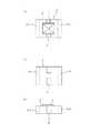
図1(a),(b),(c)に、本発明に従う点火素子搭載コンデンサの好適例を、平面、底面および側面で示す。
図中、番号1は点火素子、2はコンデンサ本体であり、この点火素子1がコンデンサ本体2の上に載置されて点火素子搭載コンデンサ3を構成している。
また、コンデンサ本体2の中央外周面には、外部端子電極4が設けられていて、この外部端子電極4は点火素子1と電気的に接続されている。なお、5−1,5−2はそれぞれコンデンサの両端に設けた両端電極である。Hereinafter, the present invention will be specifically described.
1 (a), (b), and (c) show preferred examples of the ignition element mounted capacitor according to the present invention in a plane, a bottom, and a side.
In the figure,
Further, an external
本発明のコンデンサとしては、セラミックコンデンサがとりわけ有利に適合する。ここに、コンデンサ部の容量は0.5〜10μF程度とすることが好ましい。 Ceramic capacitors are particularly advantageously adapted as capacitors according to the invention. Here, the capacitance of the capacitor portion is preferably about 0.5 to 10 μF.
なお、コンデンサとしては、セラミックコンデンサに限られるものではなく、フィルムコンデンサなど、誘電体層として耐熱性を有する樹脂を用いるものであってもよい。 The capacitor is not limited to a ceramic capacitor, and a resin having heat resistance as a dielectric layer, such as a film capacitor, may be used.
さて、本発明では、コンデンサ本体に、点火素子を載置する。この点火素子を載置する面は、コンデンサを後述するIC上に設置するための面すなわち実装面以外の面であれば、いずれでもよいが、実装面の反対側の面(コンデンサの上面)に載置することが有利である。
そして、外部端子電極と点火素子とを電気的に接続する。この接続形態については特に限定されるものではないが、以下、点火素子としてSCBとその基板からなるSCBチップを用いる場合について説明する。In the present invention, the ignition element is mounted on the capacitor body. The surface on which the ignition element is placed may be any surface as long as it is a surface for mounting the capacitor on an IC, which will be described later, that is, a surface other than the mounting surface, but the surface opposite to the mounting surface (the upper surface of the capacitor). It is advantageous to place it.
Then, the external terminal electrode and the ignition element are electrically connected. Although this connection form is not particularly limited, the case where an SCB chip comprising an SCB and its substrate is used as an ignition element will be described below.
図2(a),(b)に、その構成の一例を図解するが、番号6が薄膜抵抗(SCB)、7がその基板であり、両者でSCBチップ8を構成する。そして9が、SCB6と外部端子電極をつなぐ中継導体としてSCBチップ基板7に設けた側面電極である。
図示したとおり、SCBチップ基板7には、その上面から底面に延びる側面電極9が設けられており、SCB6は、この側面電極9を介して外部端子電極と電気的に接続している。SCB6は、例えば、Ti層とSiO2層とが交互に積層された構造を有する。なお、側面電極9の材質としては、例えばAu、Niなどを用いることができる。FIGS. 2A and 2B illustrate an example of the configuration.
As shown in the figure, the
次に、図3(a),(b)に、SCB6として絶縁層を含む積層構造のものを採用した場合の例を示す。図中、番号10はカバー電極であり、22で積層構造の絶縁層を、また23で積層構造の金属層を示す。
上述したとおり、SCB6と側面電極9との接続は、SCB6が単層の場合はそのままSCB6の両端と側面電極9が重なるようにすればよいが、SCB6が複数層で、間に絶縁層22が含まれる場合は、SCBの両端と側面電極9にまたがる位置にカバー電極10を設けることでSCB両端と側面電極9の導通を確保することができる。Next, FIGS. 3A and 3B show an example in which a laminated structure including an insulating layer is used as the
As described above, when the
次に、別の接続形態について説明する。
また、図4は、側面電極の別例としてサイドスルーホール電極11を用いた場合である。このサイドスルーホール電極11は、SCB6を成膜する前に基板7にスルーホール電極を形成しておき、SCB6を成膜後、最終工程でチップに分割するときにこのスルーホール上を切断することで、半円形のサイドスルーホール電極11がSCBチップ基板7の側面に露出した形で形成される。なお、このサイドスルーホール電極11の形状は、円形だけでなく、マイクロブラストやレーザー加工などを用いることによって、任意の形状にすることができる。そして、この方法を用いれば、より簡便に側面電極を形成することができる。
さらに、この方法に、金属層23と絶縁層22を含む積層構造のSCB6を採用した場合でも、前述したようにカバー電極10を用いることでサイドスルーホール電極11との導通を確保することができる。Next, another connection form will be described.
FIG. 4 shows a case where the side through-hole electrode 11 is used as another example of the side electrode. The side through-hole electrode 11 is formed by forming a through-hole electrode on the
Further, even when the
SCBチップの基板の材質としては、プリント回路基板として使用されるものであればいずれでも良いが、特にガラス基板、セラミック基板、LTCC(Low temperature Co-fired Multilayer Ceramic Substrates)およびシリコン基板等が好ましい。というのは、発熱抵抗体に通電することにより発熱抵抗体は発熱する。この熱を受けて火薬は、点火する温度である約300℃に達して発火する。それゆえ、基板材質としてはこのときの基板温度まで安定な材質であることが好ましいからである。 The material of the substrate of the SCB chip may be any material as long as it can be used as a printed circuit board, but glass substrates, ceramic substrates, LTCC (Low Temperature Co-fired Multilayer Ceramic Substrates), silicon substrates and the like are particularly preferable. This is because the heating resistor generates heat by energizing the heating resistor. In response to this heat, the explosives ignite when reaching an ignition temperature of about 300 ° C. Therefore, the substrate material is preferably a material that is stable up to the substrate temperature at this time.
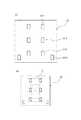
次に、上記した点火素子搭載コンデンサを載置するICについて説明する。
図5に示すように、このIC12は、コンデンサの両端電極と接続するための電極パッド、外部端子電極と接続するための電極パッドおよび外部接続用の電極ピンと接続するための電極パッドをそなえており、かような電極パッドを介して点火素子を作動させるわけである。
図中、12−1がコンデンサの両端電極5−1と接続するための第1の電極パッド、12−2が同じくコンデンサの両端電極5−2と接続するための第2の電極パッド、12−3が外部端子電極と接続するための第3の電極パッド、そして12−4が電極ピンと接続するための第4の電極パッド(通信用電極)である。
かようなICの基板素材としては、シリコン等が有利に適合する。Next, an IC on which the above ignition element mounting capacitor is mounted will be described.
As shown in FIG. 5, this
In the figure, 12-1 is a first electrode pad for connecting to both end electrodes 5-1 of the capacitor, 12-2 is a second electrode pad for connecting to both end electrodes 5-2 of the capacitor, 12-
Silicon or the like is advantageously suitable as a substrate material for such an IC.
このICに対して、電極ピンに接続されたIC12の第4の電極パッド12−4を通して外部から通信の信号が伝達される。IC12は、信号から必要な情報を取り出すと同時に、第1,第2の電極パッド12−1,12−2に接続された両端電極を通してコンデンサに、点火素子の点火のためのエネルギーを蓄積する。また、第3の電極パッド12−3は、外部端子電極を通してSCBに接続される。IC12は、通信によってエアバッグシステムの中央制御装置と情報の交換を行うことができ、中央制御装置が自動車の衝突を検知した場合、信号により所望のICに点火の命令が伝達される。その信号により所望のスクイブを点火するわけであるが、点火が所望されたスクイブのICは、IC内部のスイッチング回路によって、コンデンサに蓄積されたエネルギーをSCBに流すことができる。コンデンサからエネルギーが供給されるとSCBは加熱され火薬を点火する。 A communication signal is transmitted from the outside to the IC through the fourth electrode pad 12-4 of the
次に、上記したようなICおよび点火素子搭載コンデンサを内蔵するヘッダアッシーについて説明する。
図6に、本発明に従う好適なヘッダアッシーを例示する。
図中、番号13はヘッダー、14は電極ピン、そして15はかかる電極ピン14を互いに絶縁するための封止ガラスである。
そして、ヘッダー13の上にIC12を載置し、このIC12の上に点火素子搭載コンデンサ3を載置することにより、ヘッダアッシー16を構成している。なお、図中番号2−1でコンデンサの実装面を示す。Next, the header assembly incorporating the above-described IC and ignition element mounting capacitor will be described.
FIG. 6 illustrates a preferred header assembly according to the present invention.
In the figure,
The
ここに、点火素子搭載コンデンサの両端電極5−1,5−2(図1参照)およびコンデンサ本体2の中央外周面に設けた外部端子電極4(図1参照)と、IC12(図5参照)に設けた第1,第2,第3の電極パッド12−1,12−2,12−3(図5参照)との接続手段としてはハンダや導電ペーストが有利に適合する。
また、IC12に設けた第4の電極パッド12−4と電極ピン14を接続するにもハンダや導電ペーストを使用することが有利である。なお、この場合、ハンダや導電ペーストを絶縁物で覆う必要がある、また、ヘッダーの上面を後述する樹脂で覆う場合には、第4の電極パッド12−4と電極ピン14の接続はワイヤボンディングを利用することもできる。Here, both end electrodes 5-1 and 5-2 (see FIG. 1) of the capacitor mounted with the ignition element, the external terminal electrode 4 (see FIG. 1) provided on the central outer peripheral surface of the
It is also advantageous to use solder or conductive paste to connect the fourth electrode pad 12-4 provided on the
さらに、図7に、本発明の別のヘッダアッシーを示す。
この例は、一方の電極ピン14′をヘッダー13の金属部に直接取り付けた場合である。
このようにヘッダーの金属部と一方の電極ピンが接続された構造とすることにより、電極ピンとヘッダー金属部に静電気が印加された場合でも確実に誤発火が防げるようになる。Further, FIG. 7 shows another header assembly of the present invention.
In this example, one
By adopting a structure in which the metal part of the header and one of the electrode pins are connected in this manner, even when static electricity is applied to the electrode pins and the header metal part, it is possible to reliably prevent misfire.
ところで、図6および図7に示したところから明らかなように、ヘッダー13の上に、IC12と点火素子搭載コンデンサ3を載置した場合、この載置領域は、IC12と点火素子搭載コンデンサ3の厚みの分だけ、ヘッダー13から突出する。
このように、ヘッダー13の上面に段差が生じていると、かかるヘッダーアッシー16をカップ体内に挿入して点火薬と圧接させた場合、突出した点火素子6の上方の点火薬は密に圧縮される反面、その周りの領域は密度が疎になるため、スクイブを作動させたときに、点火感度や点火時間のばらつきが大きく、スクイブの作動安定性が阻害されるおそれがある。6 and 7, when the
Thus, if there is a step on the upper surface of the
かような弊害を解消するためには、ヘッダー上を、外径がヘッダーの外周径に等しく、かつ頭部が少なくとも点火素子の高さレベルに達する樹脂で覆うことが好ましい。
このような樹脂被覆を形成するには、例えば図8に示すように、ヘッダー13の外周に、その頭部が少なくとも点火素子6の高さレベルとほぼ等しい円筒状のカラー17を設け、その内側に樹脂18を充填してやればよい。In order to eliminate such adverse effects, it is preferable to cover the header with a resin whose outer diameter is equal to the outer peripheral diameter of the header and whose head reaches at least the height level of the ignition element.
In order to form such a resin coating, for example, as shown in FIG. 8, a
このようして樹脂18を充填することにより、円筒状カラー17の内部エリアは平坦化され、その結果、カップ体内の点火薬の圧縮密度を均一化することができる。
なお、その際、充填した樹脂18が点火素子6の素子面を覆うと、点火薬を点火させることができなくなるので、樹脂18の充填に際しては、点火素子6の素子面を除く領域に充填することが重要である。By filling the
At this time, if the filled
なお、樹脂18を充填する場合、点火素子6と同じ高さレベルとすることが最適であるのは前述したとおりであるが、点火素子6の高さレベルとその周りに充填する樹脂18の高さレベルを等しくしようとすると、充填した樹脂18が点火素子6の素子面まで覆ってしまうおそれがある。
そこで、発明者らは、点火素子6の素子面と樹脂18の上面との高さレベル差とスクイブの作動安定性との関係について調査した結果、この高さレベル差が好ましくは0.5mm以内、さらに好ましくは0.3mm以内であれば、スクイブの作動安定性にほとんど差異は生じないことを確認した。When filling the
Therefore, as a result of investigating the relationship between the height level difference between the element surface of the
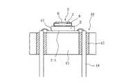
次に、上記したようなヘッダアッシーを、内部に点火薬を有するカップ体の開口部に圧入・固定して完成させたスクイブの全体を、図9に断面で示す。
図9中、番号19が点火薬、20がカップ体、21が保護用樹脂カップである。図示したとおり、円筒状のカラー17の内側に樹脂18を充填することにより、ヘッダー13の上面は平坦になっているので、かようなヘッダアッシーをカップ体内に圧入したとしても、点火薬密度にムラが生じることはなく、従ってスクイブを作動させたときに、点火感度や点火時間のばらつきが生じることはない。Next, FIG. 9 shows a cross section of the entire squib completed by press-fitting and fixing the header assembly as described above into the opening of the cup body having an ignition agent therein.
In FIG. 9,
本発明に使用する点火薬としては、その組成中にジルコニウムを含むものが好適である。その他、水素化チタンやボロン、トリシネート等を含むものも有利に適合する。また、その他に特開2002−362992号公報に開示のものが使用でき、特に限定されるものではない。そしてかかる点火薬に接触させて発熱抵抗体である薄膜抵抗を配置する。 As the igniting agent used in the present invention, those containing zirconium in the composition are suitable. In addition, those containing titanium hydride, boron, tricinate, etc. are also advantageously adapted. In addition, those disclosed in JP-A-2002-362992 can be used, and are not particularly limited. Then, a thin film resistor which is a heating resistor is placed in contact with the igniting agent.
また、本発明では、点火素子の上面に、予め点火薬組成物を塗布しておくこともできる。すなわち、薄膜抵抗の上面にスラリー状の点火薬をディスペンスし、乾燥させる。この点火薬組成物は粉末状の点火薬を単に充填した場合に比べると点火薬と薄膜抵抗の接触が安定であるため、確実な点火と点火時間の短縮に有効に寄与する。 Moreover, in this invention, an ignition agent composition can also be beforehand apply | coated to the upper surface of an ignition element. That is, a slurry-like igniter is dispensed on the upper surface of the thin film resistor and dried. Since this igniter composition is more stable in contact between the igniter and the thin film resistor than in the case where the powder igniter is simply filled, it effectively contributes to reliable ignition and shortening of the ignition time.
次に、本発明の点火装置を用いたエアバッグ用ガス発生装置について説明する。
図10に、エアバッグ用ガス発生装置の概念図を示す。同図に示したとおり、エアバッグ用ガス発生装置31は、その内部にスクイブ32、エンハンサー剤33、ガス発生剤34、フィルター35を有し、外部はガス発生剤34の燃焼圧力に耐え得る外郭容器36からなる。外郭容器36には、発生したガスをエアバッグ側に放出するための孔37が開けられている。
スクイブ32が作動すると、スクイブ32から発生する熱エネルギーでエンハンサー剤33が燃焼し火炎および熱粒子を発生する。この火炎および熱粒子によりガス発生剤34が燃焼し、エアバッグを膨らませるためのガスが発生する。このガスは、エアバッグの外郭容器36に開いた孔37から外部に放出されるが、このときフィルター35を通過させることで燃焼したガス発生剤の残渣が捕集されると同時にガス自身が冷却される。Next, a gas generator for an air bag using the ignition device of the present invention will be described.
FIG. 10 shows a conceptual diagram of a gas generator for an air bag. As shown in the figure, the
When the
さらに、本発明の点火装置を用いたシートベルトプリテンショナー用ガス発生装置について説明する。
図11に、シートベルトプリテンショナー用ガス発生装置(マイクロガスジェネレータ)の概念図を示す。同図に示したとおり、マイクロガスジェネレータ41は、その内部にスクイブ42とガス発生剤43を有し、スクイブ42はホルダーと呼ばれる基台44に固定されている。さらにガス発生剤43を格納するカップ体45も、ホルダーに例えばカシメによつて固定された構造になっている。スクイブ42が作動すると、スクイブ42からの火炎および熱粒子により、カップ体45内のガス発生剤43が燃焼してガスが発生する。Furthermore, a gas generator for a seat belt pretensioner using the ignition device of the present invention will be described.
FIG. 11 shows a conceptual diagram of a gas generator for a seat belt pretensioner (micro gas generator). As shown in the figure, the
次に、中央制御ユニットによる制御要領について説明する。
図12は、中央制御ユニット110と、4つのエアバッグモジュール111a,111b,111c,111dとを接続したLAN化されたエアバッグシステムの例を示したものである。2つのエアバッグモジュール111bと111cは各々、例えばフロントエアバッグを膨張させるガス発生器を有することができ、他の2つのエアバッグモジュール111aと111dは各々、例えばサイドエアバッグを膨張させるガス発生器を有することができる。Next, the control procedure by the central control unit will be described.
FIG. 12 shows an example of a LAN-configured airbag system in which a
これらモジュールの各々に含まれるガス発生器内に点火装置が収納されていて、各点火装置は2つの電極ピン114,115を有し、電極ピン114が中央制御ユニット110に連絡された第1の電気供給導電体112に接続され、電極ピン115が中央制御ユニット110に連絡された第2の電気供給導電体113に接続されている。 An ignition device is housed in a gas generator included in each of these modules. Each ignition device has two
通常の動作状態、すなわち自動車が1以上のエアバッグモジュール111a,111b,111c,111dを活性化することを求める特定の衝撃に巻き込まれていない時には、中央制御ユニット110は定期的に該電気供給導電体112,113に低い強度の電流を与え、この電流は電極ピン114と115を介して4つのエアバッグモジュール111a,111b,111c,111dの各々に含まれる点火装置の電気エネルギー蓄積手段(コンデンサー)に送られる。 During normal operating conditions, i.e., when the vehicle is not involved in a specific shock that seeks to activate one or more airbag modules 111a, 111b, 111c, 111d, the
衝撃が生じて、例えばエアバッグ111cを活性化することが望ましい場合には、中央制御ユニット110は第1の電気供給導電体112にエアバッグモジュール111cの点火装置のための点火コマンドを構成する特有の電気パルスの列を送る。この特有の電気パルスの列は電極ピン114と115を介して各点火装置に送られるが、エアバッグモジュール111cの点火装置に含まれるICのみがそのコマンドに反応してコンデンサから電気エネルギーを点火素子に供給し、上述したように点火薬を点火する。 In the event that an impact occurs and it is desirable to activate the airbag 111c, for example, the
もし、衝撃に続いて幾つかのエアバッグモジュール、例えばエアバッグモジュール111a,111bを活性化することが望ましい場合には、中央制御ユニット110は、第1の電気供給導電体112にエアバッグモジュール111aと111bの各々に含まれる点火装置のための特有の電気パルスの列を与える。2つの点火装置の各々の動作は上述したとおりである。 If it is desired to activate several airbag modules, such as airbag modules 111a, 111b, following an impact, the
1 点火素子
2 コンデンサ本体
2−1 コンデンサの実装面
3 点火素子搭載コンデンサ
4 外部端子電極
5−1 コンデンサの両端電極
5−2 コンデンサの両端電極
6 薄膜抵抗(SCB)
7 SCB基板
8 SCBチップ
9 側面電極
10 カバー電極
11 サイドスルーホール電極
12 IC
12−1 コンデンサの両端電極と接続するための第1の電極パッド
12−2 コンデンサの両端電極と接続するための第2の電極パッド
12−3 外部端子電極と接続するための第3の電極パッド
12−4 電極ピンと接続するための第4の電極パッド
13 ヘッダー
14,14′電極ピン
15 封止ガラス
16 ヘッダアッシー
17 円筒状カラー
18 樹脂
19 点火薬
20 カップ体
21 保護用樹脂カップ
22 絶縁層
23 金属層
31 エアバッグ用ガス発生装置
32 スクイブ
33 エンハンサー剤
34 ガス発生剤
35 フィルター
36 外郭容器
37 孔
41 シートベルトプリテンショナー用ガス発生装置(マイクロガスジェネレータ)
42 スクイブ
43 ガス発生剤
44 基台(ホルダー)
45 カップ体
110 中央制御ユニット
111a〜111d エアバッグモジュール
114,115 電極ピンDESCRIPTION OF
7 SCB substrate 8 SCB chip 9 Side electrode
10 Cover electrode
11 Side through-hole electrode
12 IC
12-1 First electrode pad to connect to both ends of capacitor
12-2 Second electrode pad to connect to both ends of capacitor
12-3 Third electrode pad for connection with external terminal electrode
12-4 Fourth electrode pad for connection with electrode pin
13 Header
14, 14 'electrode pin
15 Sealing glass
16 Header assembly
17 Cylindrical collar
18 resin
19 Ignition
20 cup body
21 Protective resin cup
22 Insulating layer
23 Metal layer
31 Gas generator for airbags
32 Squibb
33 Enhancer
34 Gas generant
35 Filter
36 outer container
37 holes
41 Gas generator for seat belt pretensioner (micro gas generator)
42 Squibb
43 Gas generant
44 Base (holder)
45 cup body
110 Central control unit
111a to 111d airbag module
114,115 electrode pin
Claims (7)
Translated fromJapanese該複数の電極ピンを互いに絶縁して保持するヘッダーと、
コンデンサの両端に両端電極および中央外周面に点火素子と電気的に接続するための外部端子電極をそなえ、該外部端子電極の上に点火素子を載置した点火素子搭載コンデンサと、
該点火素子搭載コンデンサの該両端電極および該外部端子電極と電気的に接続される第1、第2および第3の電極パッドならびに外部との通信のためにヘッダーの電極ピンに電気的に接続するための通信用電極をそなえるICとを有し、
該ヘッダー上に該ICを設置し、該IC上に該点火素子搭載コンデンサを設置して、該両端電極と該第1、該第2の電極パッドを接続し、かつ該外部端子電極と該第3の電極パッドを接続すると共に、該ICに設けた該通信用電極を通して該電極ピンと電気的に接続したことを特徴とするヘッダーアッシー。A header assembly that has a plurality of electrode pins and closes an opening of a cup body containing an ignition powder,
A header for insulating and holding the plurality of electrode pins;
Includes an external terminal electrodes to be connected to the ignition element and electrically to theelectrodes at both ends and the central outer circumferential surfaceat both ends ofthe capacitor, the ignition element mounting capacitor placing the ignition element on theexternal terminal electrodes,
Ignition element mounting first isthe electrodes at both ends and the external terminal electrodes electrically connected to the capacitor, electrically connected to the electrode pins of the header for communication with the second and third electrode pads and external And an IC having a communication electrode for
The IC is installed on the header, the ignition element mounted capacitor is installed on the IC, the both end electrodes and the first and second electrode pads are connected, and the external terminal electrode and the first electrode 3. A header assembly comprising:three electrode pads connected to each other and electrically connected to the electrode pins through the communication electrode provided in the IC.
Priority Applications (5)
| Application Number | Priority Date | Filing Date | Title |
|---|---|---|---|
| JP2006326222AJP4714669B2 (en) | 2006-12-01 | 2006-12-01 | Gas generator for header assembly, squib and airbag and gas generator for seat belt pretensioner |
| PCT/JP2007/073229WO2008066174A1 (en) | 2006-12-01 | 2007-11-30 | Header assembly, squib, airbag gas generating device, and seatbelt pretentioner gas generating device |
| US12/516,980US8104403B2 (en) | 2006-12-01 | 2007-11-30 | Header assembly, squib and gas generator for air bag and gas generator for seat belt pretensioner |
| CN200780050551ACN101627279A (en) | 2006-12-01 | 2007-11-30 | Roof module, ignition device, gas generator for airbag, and gas generator for seatbelt pretensioner |
| EP07832894.5AEP2093533B1 (en) | 2006-12-01 | 2007-11-30 | Header assembly, squib, airbag gas generating device, and seatbelt pretentioner gas generating device |
Applications Claiming Priority (1)
| Application Number | Priority Date | Filing Date | Title |
|---|---|---|---|
| JP2006326222AJP4714669B2 (en) | 2006-12-01 | 2006-12-01 | Gas generator for header assembly, squib and airbag and gas generator for seat belt pretensioner |
Publications (2)
| Publication Number | Publication Date |
|---|---|
| JP2008138946A JP2008138946A (en) | 2008-06-19 |
| JP4714669B2true JP4714669B2 (en) | 2011-06-29 |
Family
ID=39467960
Family Applications (1)
| Application Number | Title | Priority Date | Filing Date |
|---|---|---|---|
| JP2006326222AExpired - Fee RelatedJP4714669B2 (en) | 2006-12-01 | 2006-12-01 | Gas generator for header assembly, squib and airbag and gas generator for seat belt pretensioner |
Country Status (5)
| Country | Link |
|---|---|
| US (1) | US8104403B2 (en) |
| EP (1) | EP2093533B1 (en) |
| JP (1) | JP4714669B2 (en) |
| CN (1) | CN101627279A (en) |
| WO (1) | WO2008066174A1 (en) |
Families Citing this family (9)
| Publication number | Priority date | Publication date | Assignee | Title |
|---|---|---|---|---|
| JP4813904B2 (en)* | 2006-01-06 | 2011-11-09 | 日本化薬株式会社 | Ignition device, manufacturing method thereof, gas generator for airbag, and gas generator for seat belt pretensioner |
| CN101365921A (en)* | 2006-01-06 | 2009-02-11 | 日本化药株式会社 | Ignition device, air bag, and gas generator for seat belt pretensioner |
| EP2351980B1 (en)* | 2008-11-05 | 2017-01-25 | Nipponkayaku Kabushikikaisha | Ignition system, gas generating device for airbag, and gas generating device for seatbelt pretensioner |
| SG181715A1 (en) | 2009-12-18 | 2012-07-30 | Janssen Pharmaceutica Nv | Bicyclic thiazoles as allosteric modulators of mglur5 receptors |
| ES2431302T3 (en) | 2009-12-18 | 2013-11-25 | Janssen Pharmaceutica, N.V. | Bicyclic thiazoles as allosteric modulators of mGluR5 receptors |
| CN103017197B (en)* | 2011-09-23 | 2014-10-01 | 中国电子科技集团公司第四十八研究所 | A method of manufacturing a leadless encapsulated film bridge igniter |
| CN105659051B (en)* | 2013-09-10 | 2017-09-05 | 株式会社大赛璐 | Igniter assembly, airbag system, detection system and detection method thereof |
| CN113424280B (en)* | 2019-02-13 | 2023-01-03 | 京瓷Avx元器件公司 | Multilayer ceramic capacitor including conductive path |
| CN115947642A (en)* | 2022-12-26 | 2023-04-11 | 重庆云铭科技股份有限公司 | A conductive ignition powder structure and its manufacturing method |
Family Cites Families (23)
| Publication number | Priority date | Publication date | Assignee | Title |
|---|---|---|---|---|
| JPH03115619U (en)* | 1990-03-06 | 1991-11-29 | ||
| JPH03118047U (en)* | 1990-03-16 | 1991-12-05 | ||
| JPH03118048U (en)* | 1990-03-16 | 1991-12-05 | ||
| WO1994019661A1 (en) | 1993-02-26 | 1994-09-01 | Quantic Industries, Inc. | Improved semiconductor bridge explosive device |
| US6199484B1 (en)* | 1997-01-06 | 2001-03-13 | The Ensign-Bickford Company | Voltage-protected semiconductor bridge igniter elements |
| WO1999002937A1 (en)* | 1997-07-09 | 1999-01-21 | Siemens Aktiengesellschaft | Igniter |
| FR2784176B1 (en)* | 1998-10-06 | 2004-11-26 | Livbag Snc | ELECTRO-PYROTECHNIC INITIATION SYSTEM PROTECTED AGAINST ELECTROSTATIC DISCHARGES |
| US6166452A (en)* | 1999-01-20 | 2000-12-26 | Breed Automotive Technology, Inc. | Igniter |
| JP3342850B2 (en)* | 1999-05-26 | 2002-11-11 | 日本工機株式会社 | Igniter and header assembly |
| DE50014523D1 (en)* | 1999-08-25 | 2007-09-13 | Conti Temic Microelectronic | Pyrotechnic ignition system with integrated ignition circuit |
| DE10116189A1 (en)* | 2001-03-31 | 2002-10-10 | Bosch Gmbh Robert | Exploding bridge |
| JP4811975B2 (en)* | 2001-06-06 | 2011-11-09 | 日本化薬株式会社 | Ignition composition and igniter using the ignition composition |
| JP2003205823A (en)* | 2002-01-16 | 2003-07-22 | Showa Kinzoku Kogyo Kk | Gas generator |
| US7168737B2 (en)* | 2002-01-25 | 2007-01-30 | Daicel Chemical Industries, Ltd. | Integrated circuit for air bag system |
| WO2003064220A1 (en)* | 2002-01-25 | 2003-08-07 | Daicel Chemical Industries, Ltd. | Air bag system |
| US6820557B2 (en)* | 2002-01-25 | 2004-11-23 | Daicel Chemical Industries, Ltd. | Igniter for air bag system |
| US7155353B2 (en)* | 2002-04-25 | 2006-12-26 | Daicel Chemical Industries, Ltd. | Method for determining charging capacitance of capacitor |
| US7343859B2 (en)* | 2003-11-10 | 2008-03-18 | Honda Motor Co., Ltd. | Squib |
| JP2005308339A (en)* | 2004-04-23 | 2005-11-04 | Nippon Kayaku Co Ltd | Ignitor and gas generator having the same |
| JP4397731B2 (en)* | 2004-05-12 | 2010-01-13 | 日本化薬株式会社 | Ignition device |
| JP3115619U (en)* | 2005-08-09 | 2005-11-10 | 日本化薬株式会社 | Igniter |
| JP3118048U (en)* | 2005-10-27 | 2006-01-19 | 日本化薬株式会社 | Squib |
| JP3118047U (en)* | 2005-10-27 | 2006-01-19 | 日本化薬株式会社 | Squib |
- 2006
- 2006-12-01JPJP2006326222Apatent/JP4714669B2/ennot_activeExpired - Fee Related
- 2007
- 2007-11-30CNCN200780050551Apatent/CN101627279A/enactivePending
- 2007-11-30USUS12/516,980patent/US8104403B2/ennot_activeExpired - Fee Related
- 2007-11-30WOPCT/JP2007/073229patent/WO2008066174A1/enactiveApplication Filing
- 2007-11-30EPEP07832894.5Apatent/EP2093533B1/ennot_activeNot-in-force
Also Published As
| Publication number | Publication date |
|---|---|
| EP2093533A1 (en) | 2009-08-26 |
| CN101627279A (en) | 2010-01-13 |
| WO2008066174A1 (en) | 2008-06-05 |
| US20100066067A1 (en) | 2010-03-18 |
| US8104403B2 (en) | 2012-01-31 |
| JP2008138946A (en) | 2008-06-19 |
| EP2093533B1 (en) | 2013-11-20 |
| EP2093533A4 (en) | 2012-10-31 |
Similar Documents
| Publication | Publication Date | Title |
|---|---|---|
| JP4714669B2 (en) | Gas generator for header assembly, squib and airbag and gas generator for seat belt pretensioner | |
| JP4653718B2 (en) | Gas generator for squib and airbag and gas generator for seat belt pretensioner | |
| JP4668889B2 (en) | Ignition element mounted capacitor, header assembly, squib, gas generator for airbag and gas generator for seat belt pretensioner | |
| KR100475778B1 (en) | Electropyrotechnic igniter with two ignition heads and use in motor vehicle safety | |
| JP4902542B2 (en) | Semiconductor bridge, igniter, and gas generator | |
| JP5285711B2 (en) | Ignition system, gas generator for airbag, and gas generator for seat belt pretensioner | |
| JP4944584B2 (en) | Gas generator for header assembly, squib and airbag and gas generator for seat belt pretensioner | |
| US20100018431A1 (en) | Squib, Gas Generator for Air Bag and Gas Generator for Seat Belt Pretensioner | |
| JP4914193B2 (en) | Gas generator for squib and airbag and gas generator for seat belt pretensioner | |
| JP4813904B2 (en) | Ignition device, manufacturing method thereof, gas generator for airbag, and gas generator for seat belt pretensioner | |
| JP4996481B2 (en) | Ignition device, gas generator for airbag, and gas generator for seat belt pretensioner | |
| JP3118048U (en) | Squib | |
| JP3115619U (en) | Igniter | |
| JP2008138931A (en) | Semiconductor device | |
| JP3118047U (en) | Squib | |
| JP5118917B2 (en) | Gas generator for side inflator |
Legal Events
| Date | Code | Title | Description |
|---|---|---|---|
| A621 | Written request for application examination | Free format text:JAPANESE INTERMEDIATE CODE: A621 Effective date:20091120 | |
| A711 | Notification of change in applicant | Free format text:JAPANESE INTERMEDIATE CODE: A712 Effective date:20100716 | |
| A131 | Notification of reasons for refusal | Free format text:JAPANESE INTERMEDIATE CODE: A131 Effective date:20101214 | |
| A521 | Request for written amendment filed | Free format text:JAPANESE INTERMEDIATE CODE: A523 Effective date:20110214 | |
| A01 | Written decision to grant a patent or to grant a registration (utility model) | Free format text:JAPANESE INTERMEDIATE CODE: A01 Effective date:20110308 | |
| A61 | First payment of annual fees (during grant procedure) | Free format text:JAPANESE INTERMEDIATE CODE: A61 Effective date:20110328 | |
| LAPS | Cancellation because of no payment of annual fees |