JP4714227B2 - Piezoelectric drive device, piezoelectric drive control method, and electronic device - Google Patents
Piezoelectric drive device, piezoelectric drive control method, and electronic deviceDownload PDFInfo
- Publication number
- JP4714227B2 JP4714227B2JP2008007449AJP2008007449AJP4714227B2JP 4714227 B2JP4714227 B2JP 4714227B2JP 2008007449 AJP2008007449 AJP 2008007449AJP 2008007449 AJP2008007449 AJP 2008007449AJP 4714227 B2JP4714227 B2JP 4714227B2
- Authority
- JP
- Japan
- Prior art keywords
- voltage
- piezoelectric
- displacement
- drive
- electrode
- Prior art date
- Legal status (The legal status is an assumption and is not a legal conclusion. Google has not performed a legal analysis and makes no representation as to the accuracy of the status listed.)
- Expired - Fee Related
Links
Images


Classifications
- H—ELECTRICITY
- H10—SEMICONDUCTOR DEVICES; ELECTRIC SOLID-STATE DEVICES NOT OTHERWISE PROVIDED FOR
- H10N—ELECTRIC SOLID-STATE DEVICES NOT OTHERWISE PROVIDED FOR
- H10N30/00—Piezoelectric or electrostrictive devices
- H10N30/80—Constructional details
- H10N30/802—Circuitry or processes for operating piezoelectric or electrostrictive devices not otherwise provided for, e.g. drive circuits
- H—ELECTRICITY
- H10—SEMICONDUCTOR DEVICES; ELECTRIC SOLID-STATE DEVICES NOT OTHERWISE PROVIDED FOR
- H10N—ELECTRIC SOLID-STATE DEVICES NOT OTHERWISE PROVIDED FOR
- H10N30/00—Piezoelectric or electrostrictive devices
- H10N30/101—Piezoelectric or electrostrictive devices with electrical and mechanical input and output, e.g. having combined actuator and sensor parts
- H—ELECTRICITY
- H10—SEMICONDUCTOR DEVICES; ELECTRIC SOLID-STATE DEVICES NOT OTHERWISE PROVIDED FOR
- H10N—ELECTRIC SOLID-STATE DEVICES NOT OTHERWISE PROVIDED FOR
- H10N30/00—Piezoelectric or electrostrictive devices
- H10N30/20—Piezoelectric or electrostrictive devices with electrical input and mechanical output, e.g. functioning as actuators or vibrators
- H10N30/204—Piezoelectric or electrostrictive devices with electrical input and mechanical output, e.g. functioning as actuators or vibrators using bending displacement, e.g. unimorph, bimorph or multimorph cantilever or membrane benders
- H10N30/2041—Beam type
- H10N30/2042—Cantilevers, i.e. having one fixed end
Landscapes
- General Electrical Machinery Utilizing Piezoelectricity, Electrostriction Or Magnetostriction (AREA)
Description
Translated fromJapanese本発明は、圧電駆動装置、圧電駆動制御方法及び電子デバイスに関する。本発明は、特に、複数の圧電体を積層する積層型の圧電体においてヒステリシスを低減できる圧電駆動装置、圧電駆動制御方法及び電子デバイスに関する。 The present invention relates to a piezoelectric drive device, a piezoelectric drive control method, and an electronic device. In particular, the present invention relates to a piezoelectric drive device, a piezoelectric drive control method, and an electronic device that can reduce hysteresis in a stacked piezoelectric body in which a plurality of piezoelectric bodies are stacked.
従来、2枚の圧電板を重ね合わせたバイモルフアクチュエータが知られている。例えば、特許文献1は、第1、第2の圧電板を重ね合わせて接合したバイモルフアクチュエータを開示する。当該バイモルフアクチュエータは、第1、第2の圧電板間に電圧を印加することにより、両圧電板の長さ方向に沿って互いに異なる方向に伸縮する。当該バイモルフアクチュエータは、また、一方の圧電板でアクチュエータを駆動させ、他方の圧電板をヒステリシス補正用のセンサとして用いる。そして、当該センサの出力をアクチュエータ駆動用の圧電板に印加する電圧のフィードバック制御に用いる。
圧電アクチュエータは、印加電圧の増減方向によって、印加電圧と変位量との間にヒステリシスを持つ。ヒステリシスは、圧電アクチュエータのリニアリティ特性を劣化させ、圧電アクチュエータを用いた高精度の変位量制御を困難にする問題がある。 The piezoelectric actuator has hysteresis between the applied voltage and the amount of displacement depending on the direction of increase / decrease of the applied voltage. Hysteresis degrades the linearity characteristics of the piezoelectric actuator, and makes it difficult to control the displacement with high accuracy using the piezoelectric actuator.
特許文献1に記載のバイモルフアクチュエータは、センサ用の圧電板に電圧を印加しないので、フィードバック制御を行わなければ、変位量を制御することができない。また、アクチュエータの変位量を1枚の圧電板で制御するので、リニアリティをよくすることが難しい。そこで、圧電アクチュエータの変位量を、リニアリティ良く制御できる圧電駆動装置、圧電駆動制御方法及びそれを用いた電子デバイスが求められている。 Since the bimorph actuator described in Patent Document 1 does not apply a voltage to the sensor piezoelectric plate, the displacement cannot be controlled unless feedback control is performed. Further, since the displacement amount of the actuator is controlled by a single piezoelectric plate, it is difficult to improve the linearity. Thus, there is a need for a piezoelectric drive device, a piezoelectric drive control method, and an electronic device using the same that can control the displacement amount of the piezoelectric actuator with good linearity.
上記課題を解決するために、本発明の第1の形態においては、力の印加により変形が可能な基体と、基体の第1面に直接または他の層を介して形成された第1圧電体と、第1面と略平行な基体の第2面に直接または他の層を介して形成された第2圧電体と、第1圧電体、第2圧電体および基体を有する積層体の変位量に応じた駆動電圧を生成する駆動電圧生成部と、駆動電圧により積層体が変位した場合に生じるヒステリシスを補償する補償電圧を生成する補償電圧生成部と、駆動電圧および補償電圧の各々を第1圧電体および第2圧電体の各々に印加する電圧印加部と、を備える圧電駆動装置が提供される。 In order to solve the above-described problems, in the first embodiment of the present invention, a base body that can be deformed by applying a force, and a first piezoelectric body that is formed on the first surface of the base body directly or via another layer And a displacement amount of the second piezoelectric body formed directly on the second surface of the base body substantially parallel to the first surface or via another layer, and the laminate including the first piezoelectric body, the second piezoelectric body, and the base body A driving voltage generating unit that generates a driving voltage according to the driving voltage, a compensation voltage generating unit that generates a compensating voltage that compensates for hysteresis that occurs when the stacked body is displaced by the driving voltage, and each of the driving voltage and the compensating voltage is a first voltage. There is provided a piezoelectric driving device comprising: a voltage applying unit that applies to each of the piezoelectric body and the second piezoelectric body.
本発明の第2の形態においては、力の印加により変形が可能な基体、基体の第1面に直接または他の層を介して形成された第1圧電体、および、第1面と略平行な基体の第2面に直接または他の層を介して形成された第2圧電体、を有する積層体を用意する段階と、積層体の変位量に応じた駆動電圧を生成する駆動電圧生成段階と、駆動電圧による積層体の変位におけるヒステリシスを補償する補償電圧を生成する補償電圧生成段階と、駆動電圧および補償電圧の各々を第1圧電体および第2圧電体の各々に印加する電圧印加段階と、を備える圧電駆動制御方法が提供される。 In the second embodiment of the present invention, a base body that can be deformed by application of force, a first piezoelectric body formed directly on the first surface of the base body or via another layer, and substantially parallel to the first surface. Preparing a laminated body having a second piezoelectric body formed directly on the second surface of the base body or via another layer, and generating a driving voltage corresponding to the amount of displacement of the laminated body A compensation voltage generating stage for generating a compensation voltage for compensating for hysteresis in displacement of the multilayer body by the driving voltage, and a voltage applying stage for applying each of the driving voltage and the compensation voltage to each of the first piezoelectric body and the second piezoelectric body. A piezoelectric drive control method is provided.
本発明の第3の形態においては、力の印加により変形が可能な基体、基体の第1面に直接または他の層を介して形成された第1圧電体、第1面と略平行な基体の第2面に直接または他の層を介して形成された第2圧電体、第1圧電体、第2圧電体および基体を有する積層体の変位量に応じた駆動電圧を生成する駆動電圧生成部、駆動電圧による積層体の変位におけるヒステリシスを補償する補償電圧を生成する補償電圧生成部、ならびに、駆動電圧および補償電圧の各々を第1圧電体および第2圧電体の各々に印加する電圧印加部、を有する圧電駆動装置と、圧電駆動装置の変位部に配置した変位電極と、変位電極との間で可変容量を形成する固定電極と、を備える電子デバイスが提供される。 In the third embodiment of the present invention, a base body that can be deformed by application of force, a first piezoelectric body formed directly on the first surface of the base body or via another layer, and a base body substantially parallel to the first surface Drive voltage generation for generating a drive voltage in accordance with the displacement amount of the second piezoelectric body, the first piezoelectric body, the second piezoelectric body, and the laminate having the substrate formed on the second surface of the substrate directly or via another layer , A compensation voltage generator for generating a compensation voltage for compensating for hysteresis in displacement of the multilayer body by the drive voltage, and voltage application for applying each of the drive voltage and the compensation voltage to each of the first piezoelectric body and the second piezoelectric body There is provided an electronic device comprising: a piezoelectric drive device having a portion; a displacement electrode disposed in a displacement portion of the piezoelectric drive device; and a fixed electrode that forms a variable capacitance between the displacement electrode.
なお、上記の発明の概要は、本発明の必要な特徴の全てを列挙したものではない。また、これらの特徴群のサブコンビネーションもまた、発明となりうる。 The above summary of the invention does not enumerate all necessary features of the present invention. Also, a sub-combination of these feature groups can be an invention.
以下、発明の実施の形態を通じて本発明を説明するが、以下の実施形態は特許請求の範囲にかかる発明を限定するものではない。また、実施形態の中で説明されている特徴の組み合わせの全てが発明の解決手段に必須であるとは限らない。 Hereinafter, the present invention will be described through embodiments of the invention, but the following embodiments do not limit the invention according to the claims. In addition, not all the combinations of features described in the embodiments are essential for the solving means of the invention.
図1は、本実施形態の圧電駆動装置100を備える可変容量キャパシタ10と、圧電駆動装置100を駆動する回路の機能ブロックの概要を示す。同図において圧電駆動装置100は分解斜視図として示す。分解斜視図の左側には圧電駆動装置100を長さ方向Lの中央近傍で幅方向Wに切断した断面図を示す。 FIG. 1 shows an outline of a functional block of a
可変容量キャパシタ10は、電子デバイスの一例であってよい。可変容量キャパシタ10は、圧電駆動装置100と、変位電極102と、固定電極104と、基板106と、台座部108とを備える。 The
圧電駆動装置100は、変位電極102と固定電極104との距離を制御する。圧電駆動装置100は、積層体110と、駆動電圧生成部180と、補償電圧生成部182と、電圧印加部184と、センス部190と、制御部192と、格納部194と、制御テーブル196とを有する。 The
積層体110は、電圧の印加により高さ方向H(積層方向)に変位する。積層体110は、基体120と、第1圧電体130と、第2圧電体140と、第3圧電体150とを含む。積層体110は、第1電極160と、第2電極162と、第1センス電極164と、絶縁層166と、第2センス電極168とを含む。 The stacked
基体120は、弾性を有する。これにより、力の印加により変形が可能なので、第1圧電体130または第2圧電体140が伸縮して基体120に力が印加されると、基体120は湾曲する。基体120は、剛性を有する。これにより、積層体110が撓みすぎるのを抑制する。基体120は、例えば、アルミニウム、金、白金等の導電体、ガラス等の絶縁体、シリコン等の半導体を用いてもよい。 The
基体120の一例として、幅方向Wに90μm、長さ方向Lに750μm、高さ方向Hに0.5μmの平板形状を有する白金を用いてもよい。基体120に導電体を用いることで、基体120を第1圧電体130および第2圧電体140に電圧を印加する電極として利用できる。 As an example of the
第1圧電体130は、基体120の第1面122に形成される。第1圧電体130は、電圧を印加されると歪んで伸縮する。第1圧電体130は、電圧を印加された場合に、長さ方向Lに伸縮して、高さ方向Hに積層体110を湾曲させるように配される。 The first
第1圧電体130は、例えば、窒化アルミニウム(AlN)、酸化亜鉛(ZnO)のウルツ鉱型の結晶、又は、チタン酸ジルコン酸鉛(PZT)、チタン酸ジルコン酸ランタン鉛(PLZT)、若しくはチタン酸バリウム(BTO)等のペロブスカイト系強誘電体等を用いてもよい。第1圧電体130の一例として、幅方向Wに90μm、長さ方向Lに750μm、高さ方向Hに0.5μmのPZTの圧電膜を用いてもよい。 The first
第2圧電体140は、第1面122と略平行な基体120の第2面124に形成される。第2圧電体140は、電圧を印加されると歪んで伸縮する。第2圧電体140は、電圧を印加された場合に、長さ方向Lに伸縮して、高さ方向Hに積層体110を湾曲させるように配される。第2圧電体140は、第1圧電体130と同様の圧電体を用いてもよい。第2圧電体140の一例として、幅方向Wに90μm、長さ方向Lに750μm、高さ方向Hに0.5μmのPZTの圧電膜を用いてもよい。 The second
第3圧電体150は、第2圧電体140の基体120に面する側の面142とは逆の面144に、第2電極162、第1センス電極164及び絶縁層166を介して形成される。第3圧電体150は、電圧を印加されると歪んで伸縮する。第3圧電体150は、電圧を印加された場合に、長さ方向Lに伸縮して、高さ方向Hに積層体110を湾曲させるように配される。第3圧電体150は、第1圧電体130と同様の圧電体を用いてもよい。第3圧電体150の一例として、幅方向Wに90μm、長さ方向Lに750μm、高さ方向Hに0.5μmのPZTの圧電膜を用いてもよい。 The third
第1電極160は、第1圧電体130の基体120に面する側の面132とは逆の面134に形成される。第1電極160は、積層体110の長さ方向Lに延伸する平板形状を有する。第1電極160は、例えば、アルミニウム(Al)、金(Au)、白金(Pt)、銅(Cu)、インジウム(In)、タングステン(W)、モリブデン(Mo)、ルテニウム(Ru)、イリジウム(Ir)等の低抵抗で加工が容易な金属、ルテニウムオキサイド(RuO2)、イリジウムオキサイド(IrO2)等酸化物電極、又は、シリコン(Si)等の半導体を用いてもよい。電極材料としてシリコン基板を用いる場合には、高濃度にドープされた基板を用いることが好ましい。第1電極160の一例として、高さ方向Hの厚さが0.2μmの白金を用いてもよい。The
第2電極162は、第2圧電体140の基体120に面する側の面142とは逆の面144に形成される。第2電極162は、例えば、積層体110の長さ方向Lに延伸する平板形状を有する。第2電極162の幅は、第2圧電体140の幅より短くてもよい。第2電極162は、第1電極160と同様の電極材料を用いてもよい。第2電極162の一例として、高さ方向Hの厚さが0.2μmの白金を用いてもよい。 The
第1センス電極164は、例えば、第2電極162が形成されるのと同一の面144に形成される。第1センス電極164は、例えば、積層体110の長さ方向Lに延伸する平板形状を有する。第1センス電極164は、例えば、第2電極162の幅方向Wの両端に、絶縁層166を介して配される。これにより、第1センス電極164は、第2電極162と電気的に絶縁される。第1センス電極164は、第2圧電体140の幅方向Wの両端に配置できる。 The
第1センス電極164は、第1電極160と同様の電極材料を用いてもよい。第1センス電極164は、第2電極162と略同一の厚みを有してもよい。第1センス電極164の一例として、高さ方向Hの厚さが0.2μmの白金を用いてもよい。 The
絶縁層166は、第2電極162及び第1センス電極164が形成されるのと同一の面144に形成される。絶縁層166は、積層体110の長さ方向Lに延伸する平板形状を有する。絶縁層166は、第2電極162と第1センス電極164とに挟まれるように配される。絶縁層166は、第2電極162と第1センス電極164とを電気的に絶縁する。 The insulating
絶縁層166は、例えば、酸化シリコン(SiO2)等の絶縁体を用いてもよい。絶縁層166の一例として、高さ方向Hの厚さが0.2μmのSiO2を用いてもよい。For example, an insulator such as silicon oxide (SiO2 ) may be used for the insulating
第2センス電極168は、第3圧電体150の第2圧電体140に面する側とは逆の面に形成される。第2センス電極168は、少なくとも一部が第1センス電極164と対向するように形成される。第2センス電極168は、第1センス電極164と略同一の形状を有してよい。第2センス電極168は、第3圧電体150を介して第1センス電極164と対向する位置に配されてもよい。これにより、積層体110の変位により第3圧電体150に生じた変位電圧を精度よく感知することができる。 The
積層体110は、例えば、ゾル・ゲル法、スパッタリング、CVD又はエッチング等の微細加工技術を利用して形成できる。積層体110の形成方法は微細加工技術に限られるものではなく、例えば、接着により形成されてもよい。 The
なお、本実施形態において、第1圧電体130および第2圧電体140は、基体120の第1面122または第2面124に直接形成されているが、他の層を介して形成されてもよい。他の層は、例えば、導電性の電極であってもよい。第3圧電体150は、基体120の第2面124に、第2圧電体140を介して形成されているが、基体120の第2面124に直接形成されて、基体120、第3圧電体150、第2圧電体140の順に積層されてもよい。 In the present embodiment, the first
本実施形態において、第2電極162と第1センス電極164とは、積層体110の幅方向Wに離間されることで電気的に絶縁されているが、第2電極162と第1センス電極164の絶縁方法はこれに限られるものではない。例えば、第2電極162が高さ方向Hの厚みの薄い領域を有して、当該領域に、第2電極162と第1センス電極164とが絶縁層166により絶縁されるように第1センス電極164及び絶縁層166が配されてもよい。 In the present embodiment, the
駆動電圧生成部180は、積層体110の変位量に応じた駆動電圧を生成する。駆動電圧生成部180は、制御部192より駆動電圧に関する信号が入力される。駆動電圧生成部180は、電圧印加部184に、第1電極160に当該駆動電圧を印加する旨の信号を、出力する。 The drive voltage generation unit 180 generates a drive voltage corresponding to the amount of displacement of the
補償電圧生成部182は、駆動電圧により積層体110が変位した場合に生じるヒステリシスを補償する補償電圧を生成する。補償電圧生成部182は、制御部192より補償電圧に関する信号が入力される。補償電圧生成部182は、電圧印加部184に、第2電極162に当該補償電圧を印加する旨の信号を出力する。 The compensation voltage generation unit 182 generates a compensation voltage that compensates for hysteresis that occurs when the
電圧印加部184は、駆動電圧および補償電圧の各々を、第1圧電体130および第2圧電体140の各々に印加する。電圧印加部184は、第1電源部186と、第2電源部188とを含む。 The voltage application unit 184 applies the drive voltage and the compensation voltage to each of the first
第1電源部186の出力端は、例えば、第1電極160の台座部108に固定される側の端部と接続されている。第1電源部186の接地端は、例えば、基体120の台座部108に固定される側の端部と接続されている。これにより、第1電極160に電圧を印加すると第1圧電体130の高さ方向Hに電位差が生じ、第1圧電体130が高さ方向Hに変位する。 The output end of the first
第2電源部188の出力端は、例えば、第2電極162の台座部108に固定される側の端部と接続されている。第2電源部188の接地端は、基体120の台座部108に固定される側の端部と接続されている。これにより、第2電極162に電圧を印加すると第2圧電体140の高さ方向Hに電位差が生じ、第2圧電体140が高さ方向Hに変位する。 The output end of the second
以上の構成により、電圧印加部184は、第1圧電体130と第2圧電体140にそれぞれ独立して電圧を印加することができる。なお、補償電圧生成部182は、補償電圧に重畳して変調電圧を印加してもよい。これにより、可変容量キャパシタ10を発振回路に用いることができる。また基準周波数の信号に前記の変調電圧を変調信号として重畳すれば、可変容量キャパシタ10は、周波数変調信号源、AFC(Auto Frequency Control)あるいはPLL(Phase Lock Loop)用の発振器に応用することができる。 With the above configuration, the voltage application unit 184 can apply a voltage independently to the first
センス部190は、積層体110の変位により第3圧電体150に生成される変位電圧を検出する。センス部190は、第1センス電極164及び第2センス電極168に接続されている。なお第3圧電体150の材料として圧電定数の大きな材料、たとえば単結晶材料あるいはPZTを用いることができる。圧電定数の高い材料を用いることにより、センシングの感度を高めることができる。 The
センス部190は、第1センス電極164及び第2センス電極168より電位に関する信号が入力される。センス部190は、その電位差を第3圧電体150に生成される変位電圧として検出する。センス部190は、変位電圧に関する信号を制御部192に出力する。なお、圧電駆動装置100は、センス部190と制御部192との間に増幅部を有して、センス部190で検出した変位電圧を増幅した後、制御部192に出力してもよい。 A signal related to a potential is input to the
制御部192は、駆動電圧生成部180及び補償電圧生成部182を制御する。制御部192は、積層体110の変位量を設定する。制御部192は、当該変位量に応じた駆動電圧に関する信号を駆動電圧生成部180に出力する。 The
制御部192は、センス部190より変位電圧に関する信号が入力される。制御部192は、当該変位電圧に関する信号と、駆動電圧の増減に関する信号と、格納部194に格納された制御テーブル196とに基づき、変位電圧に応じた補償電圧を求める。制御部192は、当該補償電圧に関する信号を補償電圧生成部182に出力する。 The
なお、制御部192、駆動電圧生成部180、及び、補償電圧生成部182の機能は明確に区別されるものではない。例えば、制御部192が、駆動電圧又は補償電圧を印加する旨の信号を電圧印加部184に出力してもよい。同様に、駆動電圧生成部180が積層体110の変位量に応じた駆動電圧を求めてもよく、補償電圧生成部が変位電圧に応じた補償電圧を求めても良い。 Note that the functions of the
格納部194は、制御テーブル196を格納する。制御テーブル196は、変位電圧と補償電圧との関係を予め規定する。制御テーブル196は、駆動電圧を増加する場合および駆動電圧を減少する場合の各々について、駆動電圧ごとの変位電圧を予め測定した変位電圧測定値に基づき、変位電圧と、当該変位電圧に対応する補償電圧とを規定する。 The storage unit 194 stores a control table 196. The control table 196 predefines the relationship between the displacement voltage and the compensation voltage. The control table 196 includes a displacement voltage and a compensation corresponding to the displacement voltage based on a displacement voltage measurement value obtained by measuring the displacement voltage for each drive voltage in advance when the drive voltage is increased and when the drive voltage is decreased. Specifies the voltage.
具体的には、積層体110に印加する最小電圧から最大電圧まで駆動電圧を増加させていく場合、及び、当該最大電圧から当該最小電圧まで駆動電圧を減少させていく場合の各々について、第1電極160に所定の駆動電圧を印加した場合の変位電圧をセンス部190で検出する。その後、例えば、積層体110の変位量をCCDカメラで観察しながら、積層体110の変位量が駆動電圧に対して線形となるように、第2電極162に補償電圧を印加する。変位量が駆動電圧に対して線形になる補償電圧の値が求まれば、制御テーブル196に、駆動電圧の増減を示す情報、駆動電圧、当該駆動電圧に対応する変位電圧、当該変位電圧に対応する補償電圧を記録して、格納部194に格納する。 Specifically, for each of the case where the drive voltage is increased from the minimum voltage applied to the
これにより、駆動電圧を増加させる場合と減少させる場合の各々について、変位電圧と補償電圧との関係を予め測定した測定値に基づき規定しておくことで、複雑なフィードバック回路を用いずに、積層体110の変位量を制御できる。当該関係が予め規定されているので、積層体110の変位量を迅速に制御できる。さらに、最小電圧と最大電圧の間を複数の領域に分割して、当該領域ごとに制御テーブル196を作成してもよく、これにより、より精密な変位量制御が可能になる。 As a result, for each of the cases where the drive voltage is increased and decreased, the relationship between the displacement voltage and the compensation voltage is defined based on the measured value measured in advance, so that the lamination can be performed without using a complicated feedback circuit. The amount of displacement of the
変位電極102は、圧電駆動装置100の積層体110に配される。変位電極102は、第3圧電体150の第2圧電体140に面する側とは逆の面に配されてもよい。当該面の両端近傍には、第2センス電極168が配されているので、変位電極102は、第2センス電極168と離間して配される。これにより、変位電極102と第2センス電極168とは、電気的に絶縁される。 The
変位電極102は、第1電極160と同様の電極材料を用いてもよい。変位電極102の一例として、高さ方向Hの厚さが0.2μmの白金を用いてもよい。 The
固定電極104は、変位電極102との間で可変容量を形成する。固定電極104は、少なくとも一部が変位電極102と対向するように離間して配される。固定電極104は、変位電極102と対向する位置に、高さ方向Hに離間して配されてもよい。固定電極104は、第1電極160と同様の電極材料を用いてもよい。固定電極104の一例として、高さ方向Hの厚さが0.2μmの白金を用いてもよい。 The fixed
基板106は、固定電極104を支持する平坦面を有する。基板106は、例えば、絶縁性のガラス基板、シリコン等の半導体基板を用いてもよい。基板106の一例として、シリコン基板を用いてもよい。 The
台座部108は、基板106において、固定電極104の近傍で固定電極104と離間した位置に配される。台座部108は、酸化シリコン(SiO2)等の絶縁体を用いてもよい。台座部108の一例として、SiO2を用いてもよい。The
なお、台座部108の厚みは、積層体110の最大変位量と同等もしくはそれ以上であってもよい。ここで、積層体110の最大変位量とは、積層体110に印加できる最大の電圧を印加した場合における、積層体110の変位量を意味する。 Note that the thickness of the
図2は、可変容量キャパシタ10をA−A'断面で切断した場合の概要を表す。同図に示すとおり、積層体110は、台座部108を介して基板106上に固定されてもよい。積層体110は長さ方向Lの一方の端部で台座部108に支持されている。積層体110に電圧を印加すると、積層体110において台座部108に支持されていない変位部202は、高さ方向Hに屈曲する(図中、下向きに変位する)、若しくは、反り返る(図中、上向きに変位する)ことができる。 FIG. 2 shows an outline when the
積層体110において変位部202の基板106に面した側には、変位電極102が配される。基板106において変位電極102に対向する位置には、固定電極104が配される。台座部108は高さ方向Hに厚みを有するので、積層体110に電圧が印加されていない状態において、可変容量キャパシタ10は、変位電極102と固定電極104との間に距離H1を有する。これにより、変位電極102と固定電極104との間に平板キャパシタが形成される。 A
変位部202の変位量D1は、積層体110に印加した電圧に応じて変化する。変位量D1が変化すると、積層体110に電圧が印加されている場合における変位電極102と固定電極104との距離H2も変化する。可変容量キャパシタ10の容量は変位電極102と固定電極104との距離H2に反比例するので、積層体110に印加する電圧を制御することで、可変容量キャパシタ10の容量を制御することができる。これにより、変位電極102と固定電極104との間で可変容量が形成される。 The displacement amount D <b> 1 of the displacement part 202 changes according to the voltage applied to the
なお、本実施形態において、可変容量キャパシタ10は、積層体110の一端が支持されたいわゆる片持ち梁構造を有するが、積層体110を支持する構造はこれに限られるものではない。他の構造は、例えば、積層体110の長さ方向Lにおける両端が支持され、積層体110の長さ方向Lにおける中央近傍が高さ方向Hに変位する、いわゆる両持ち梁構造であってもよい。両持ち梁構造の他の例は、円板状の積層体110を用意して、積層体110の円周部を支持して、積層体110の中心近傍を高さ方向Hに変位させてもよい。 In the present embodiment, the
図3は、圧電駆動装置100の圧電駆動制御方法の一例を示す。以下、可変容量キャパシタ10の容量を所定の容量に調整する場合について、圧電駆動装置100の圧電駆動制御方法を説明する。 FIG. 3 shows an example of a piezoelectric drive control method of the
まず、圧電駆動装置100は、駆動電圧を生成する(S10)。駆動電圧は、以下の通り生成される。 First, the
制御部192は、現在、第1電極160に印加している駆動電圧を記憶する。制御部192は、可変容量キャパシタ10の調整後の容量を形成する積層体110の変位量から第1電極160に印加すべき駆動電圧を求める。制御部192は、当該駆動電圧に関する信号を駆動電圧生成部180に出力する。駆動電圧生成部180は、制御部192から入力された駆動電圧を第1電極160に印加する旨の信号を電圧印加部184に出力する。 The
次に、圧電駆動装置100は、駆動電圧を印加する(S11)。駆動電圧は、電圧印加部184が、第1電源部186の発生させた電圧を第1電極160に印加することで、印加される。 Next, the
次に、圧電駆動装置100は、変位電圧を検出する(S12)。変位電圧は、以下の通り検出される。 Next, the
第1電極160に電圧が印加されると、第1圧電体130が歪んで伸縮して積層体110が変位する。第3圧電体150も積層体110と共に変位する。第3圧電体150が変位すると、第1センス電極164と第2センス電極168との間に第3圧電体150の変位量に応じた変位電圧が生じる。センス部190は、当該変位電圧を検出する。センス部190は、当該変位電圧に関する信号を制御部192に出力する。 When a voltage is applied to the
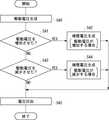
次に、制御部192は、S11において駆動電圧が増加したかどうかを判定する(S13)。駆動電圧が増加していた場合には(S13のYES)、駆動電圧が増加する場合の補償電圧を生成する(S14)。補償電圧は、以下の通り生成される。 Next, the
制御部192は、制御テーブル196に規定された、駆動電圧が増加した場合における変位電圧に対応する補償電圧を参照する。制御部192は、センス部190から入力された変位電圧に対応する補償電圧を求める。制御部192は、当該補償電圧に関する信号を補償電圧生成部182に出力する。補償電圧生成部182は、制御部192から入力された補償電圧を第2電極162に印加する旨の信号を電圧印加部184に出力する。 The
S13において、制御部192が、S11において駆動電圧が増加していないと判定した場合には(S13のNO)、制御部192は、S11において駆動電圧が減少したかどうかを判定する(S15)。駆動電圧が減少していた場合には(S15のYES)、駆動電圧が減少する場合の補償電圧を生成する(S16)。補償電圧は、以下の通り生成される。 If the
制御部192は、制御テーブル196に記憶された、駆動電圧が減少した場合における変位電圧に対応する補償電圧を参照する。制御部192は、センス部190から入力された変位電圧に対応する補償電圧を求める。制御部192は、当該補償電圧に関する信号を補償電圧生成部182に出力する。補償電圧生成部182は、制御部192から入力された補償電圧を第2電極162に印加する旨の信号を電圧印加部184に出力する。 The
次に、圧電駆動装置100は、S14又はS16で生成された補償電圧を印加する(S17)。補償電圧は、電圧印加部184が第2電源部188の発生させた電圧を第2電極162に印加することで印加される。 Next, the
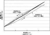
図4は、圧電駆動装置100に印加した駆動電圧に対する、積層体110の高さ方向Hにおける変位量を表す。同図において、横軸は第1電極160に印加した駆動電圧を示しており、縦軸は駆動電圧が印加された場合の積層体110の高さ方向Hにおける変位量を示す。同図において、点線は、補償電圧を印加しない場合における、駆動電圧に対する積層体110の変位量を示す。一方、実線は、図3に示した圧電駆動制御方法に基づき補償電圧を印加した場合における、駆動電圧に対する積層体110の変位量を示す。なお、同図において、縦軸および横軸は任意スケールで表されている。 FIG. 4 shows the amount of displacement in the height direction H of the
図4に示すとおり、補償電圧を印加しない場合は、積層体110にはヒステリシスが生じている。つまり、駆動電圧を増加させる場合には、積層体110の変位量は下に凸の曲線を描いて増加する。一方、駆動電圧を減少させる場合には、積層体110の変位量は上に凸の曲線を描いて減少する。 As shown in FIG. 4, when the compensation voltage is not applied, hysteresis occurs in the
これに対して、補償電圧を印加した場合には、駆動電圧と積層体110の変位量とは、ほぼ線形の関係にあることがわかる。つまり、本実施形態においては、駆動電圧を増加させる場合には、第2圧電体140が第1圧電体130の伸縮を補助するように補償電圧が印加されており、駆動電圧を減少させる場合には、第2圧電体140が第1圧電体130の伸縮を抑制するように補償電圧が印加されている。以上より、上記構成によれば、積層体自体がヒステリシスを有する場合であっても、複雑なフィードバック回路を用いずに、積層体110に印加する駆動電圧により積層体110の変位量を精度よく制御できる。 On the other hand, when the compensation voltage is applied, it can be seen that the drive voltage and the displacement amount of the
図5は、可変容量キャパシタ10の校正方法の一例を示す。駆動電圧が増加する場合及び駆動電圧が減少する場合の各々について、同図に示す手順で制御テーブル196の値を更新することで、可変容量キャパシタ10が駆動電圧に対して所定の容量を形成するように校正できる。以下、駆動電圧が増加する場合において、制御テーブル196の値を更新する手順を説明するが、駆動電圧が減少する場合の値も同様に更新できる。 FIG. 5 shows an example of a calibration method for the
まず、圧電駆動装置100は、駆動電圧を印加する(S20)。駆動電圧は、以下の通り印加される。 First, the
可変容量キャパシタ10の校正を開始する旨の信号が、制御部192に入力される。制御部192は、積層体110に印加する最小電圧を駆動電圧として、駆動電圧に関する信号を駆動電圧生成部180に出力する。制御部192は、当該駆動電圧を記憶する。駆動電圧生成部180は、制御部192から入力された駆動電圧を第1電極160に印加する旨の信号を電圧印加部184に出力する。電圧印加部184は、第1電源部186の発生させた電圧を第1電極160に印加する。 A signal to start calibration of the
次に、圧電駆動装置100は、変位電圧を検出する(S21)。変位電圧は、以下の通り検出される。 Next, the
センス部190は、第1センス電極164と第2センス電極168との間の変位電圧を検出する。センス部190は、当該変位電圧に関する信号を制御部192に出力する。制御部192は、当該変位電圧をS20において印加した駆動電圧に対応付けて記憶する。 The
次に、圧電駆動装置100は、可変容量キャパシタ10の容量を測定する。(S22)。このとき、制御部192は、可変容量キャパシタ10の容量に関する情報を取得する。 Next, the
次に、圧電駆動装置100は、補償電圧を印加する(S23)。補償電圧は、以下の通り印加される。 Next, the
制御部192は、現在の制御テーブル196を参照する。制御部192は、上記変位電圧に対応する補償電圧に関する信号を補償電圧生成部182に出力する。補償電圧生成部182は、制御部192から入力された補償電圧を第2電極162に印加する旨の信号を電圧印加部184に出力する。電圧印加部184は、第2電源部188の発生させた電圧を第2電極162に印加する。 The
次に、圧電駆動装置100は、可変容量キャパシタ10の容量を測定する(S24)。そして、制御部192は、可変容量キャパシタ10の容量に関する情報を取得する。センス部190は、検出した変位電圧を制御部192に出力してもよい(S25)。 Next, the
次に、制御部192は、S24で取得した可変容量キャパシタ10の容量が、S20で積層体110に印加した駆動電圧に対して定められた所定の容量であるか否かを判定する(S26)。S24で取得した可変容量キャパシタ10の容量が上記所定の容量でない場合には(S26のNO)、補償電圧を生成する(S27)。補償電圧は、以下の通り生成される。 Next, the
制御部192は、可変容量キャパシタ10の容量を上記所定の容量に近づけるべく、補償電圧を設定する。制御部192は、当該補償電圧に関する信号を、補償電圧生成部182に出力する。補償電圧生成部182は、制御部192から入力された補償電圧を第2電極162に印加する旨の信号を電圧印加部184に出力する。 The
ここで、上記補償電圧は、S24で取得した可変容量キャパシタ10の容量と上記所定の容量との差に応じて設定されても良く、S21でセンス部から入力された変位電圧とS25でセンス部から入力された変位電圧との差に応じて設定されてもよい。例えば、S24で取得した可変容量キャパシタ10の容量が上記所定の容量より大きい場合には、補償電圧は、積層体110の変位をより大きくするように設定される。可変容量キャパシタ10の容量が所定の容量になるまで、S23〜S27が繰り返される。 Here, the compensation voltage may be set according to the difference between the capacitance of the
S26において、可変容量キャパシタ10の容量として所定の容量が得られた場合には(S26のYES)、制御部192は、所定の容量が得られた場合の補償電圧をS20において印加した駆動電圧に対応付けて記憶する。次に、制御部192は、積層体110に印加する駆動電圧を所定量増加させて、次に積層体110に印加する駆動電圧を設定して、当該駆動電圧が最大電圧より小さいかどうかを判定する(S28)。 In S26, when a predetermined capacity is obtained as the capacity of the variable capacitor 10 (YES in S26), the
当該駆動電圧が最大電圧より小さい場合には(S28のYES)、駆動電圧を生成する(S29)。駆動電圧は、以下の通り生成される。 When the drive voltage is smaller than the maximum voltage (YES in S28), a drive voltage is generated (S29). The drive voltage is generated as follows.
制御部192は、S28で設定された駆動電圧を駆動電圧として設定する。制御部192は、当該駆動電圧に関する信号を駆動電圧生成部180に出力する。駆動電圧生成部180は、制御部192から入力された駆動電圧を第1電極160に印加する旨の信号を電圧印加部184に出力する。上記駆動電圧が最大電圧より大きくなるまで、S20〜S29が繰り返される。 The
次に、圧電駆動装置100は、制御テーブル196を更新する(S30)。制御テーブル196は以下の通り更新される。 Next, the
S28において、上記駆動電圧が最大電圧より大きくなった場合には、S20で印加した駆動電圧、S21で記憶した変位電圧、S26で記憶した補償電圧を用いて、制御テーブル196を更新する。更新された制御テーブル196は、格納部194に格納される。 If the drive voltage becomes larger than the maximum voltage in S28, the control table 196 is updated using the drive voltage applied in S20, the displacement voltage stored in S21, and the compensation voltage stored in S26. The updated control table 196 is stored in the storage unit 194.
図6は、別の実施形態に係る圧電駆動装置600の概要を表す。同図に示す通り、圧電駆動装置600は、積層体610を有して、センス部190において、積層体610の変位により第2圧電体140に生成される変位電圧を検出する点で、圧電駆動装置100と相違する。これにより、積層体610は第3圧電体150を有しないので、圧電駆動装置の製作が容易になり、より少ない電力で積層体を変位させることができる。なお、図1と共通の要素には同じ参照番号を付して重複する説明を省く。 FIG. 6 shows an outline of a
図6に、積層体610を幅方向Wに切断した場合の断面図を示す。圧電駆動装置600においては、第2圧電体140に生成される変位電圧を検出する。圧電駆動装置600は、積層体610を有する。積層体610は、第2電極662と、絶縁層666と、センス電極668とを含む。 FIG. 6 shows a cross-sectional view when the
第2電極662は、第2圧電体140の基体120に面する側の面142とは逆の面144に形成される。第2電極662は、積層体610の長さ方向Lに延伸する。第2電極662は、第1電極160と同様の電極材料を用いてもよい。第2電極662は、第2電源部188に接続される。 The
絶縁層666は、第2電極662が形成されるのと同一の面144に形成される。絶縁層666は、第2電極662とセンス電極668とを電気的に絶縁する。絶縁層666は、例えば、酸化シリコン(SiO2)等の絶縁体を用いてもよい。The insulating
センス電極668は、第2電極662が形成されるのと同一の面144に形成される。センス電極668は、センス部190に接続される。第2電極662とセンス電極668とは、絶縁層666により電気的に絶縁される。 The
センス部190には、基体120及びセンス電極668より電位の情報が入力される。センス部190は、その電位差を第2圧電体140に生成される変位電圧として検出する。センス部190は、当該変位電圧に関する信号を制御部192に出力する。なお、圧電駆動装置600に変位電極102を配置する場合には、変位電極102は、積層体610の適切な部分に電気的に絶縁されて配される。 Potential information is input to the
図7は、別の実施形態に係る圧電駆動装置700の概要を表す。同図に示す通り、圧電駆動装置700は、センス部190で検出した変位電圧を補償電圧生成部782にフィードバックして補償電圧を生成する点で、圧電駆動装置600と相違する。以上の構成により、圧電駆動装置700は、変位電圧の目標値が予め定まっているので、フィードバック制御をした場合であっても、フィードバック回路が複雑にならない。なお、図1と共通の要素には同じ参照番号を付して重複する説明を省く。 FIG. 7 shows an outline of a
同図に示す通り、圧電駆動装置700は、制御部792を有する。圧電駆動装置700は、制御テーブル796を、格納部194に格納する。制御テーブル796は、駆動電圧が増加する場合及び駆動電圧が減少する場合の各々について、駆動電圧と、当該駆動電圧に対応した変位電圧の目標値とを規定する。 As shown in the figure, the
制御部792は、駆動電圧の増減に関する情報と、駆動電圧と、制御テーブル796とに基づき、変位電圧の目標値を設定する。制御部792は、当該目標値に関する信号を補償電圧生成部782に出力する。補償電圧生成部782は、センス部190から入力された変位電圧と制御部792から入力された変位電圧の目標値に基づき、センス部190から入力された変位電圧を当該目標値に近づけるような補償電圧を第2電極162に印加する旨の信号を電圧印加部184に出力する。 The
図8は、別の実施形態に係る圧電駆動装置800の概要を表す。同図に示す通り、圧電駆動装置800は、積層体810を有して、センス部190を用いずに補償電圧を印加する点で、圧電駆動装置600と相違する。これにより、圧電駆動装置の構造が更に簡素化される。なお、図1と共通の要素には同じ参照番号を付して重複する説明を省く。 FIG. 8 shows an outline of a
図8に、積層体810を幅方向Wに切断した場合の断面図を示す。積層体810は、第2電極862を含む。第2電極862は、第2圧電体140の基体120に面する側の面142とは逆の面144に配される。第2電極862は、第1電極160と同様の電極材料を用いてもよい。第2電極862は、第2電源部188に接続される。 FIG. 8 shows a cross-sectional view when the
同図に示す通り、圧電駆動装置800は、制御部892を有する。圧電駆動装置800は、制御テーブル896を、格納部194に格納する。 As shown in the figure, the
制御テーブル896は、駆動電圧が増加する場合及び駆動電圧が減少する場合の各々について、駆動電圧と、当該駆動電圧に対応した補償電圧とを規定する。制御テーブル896は、駆動電圧ごとの積層体810の変位量を予め測定して変位量測定値を求め、当該変位量測定値が駆動電圧に対して線形となるような補償電圧を予め測定することで得られる。 The control table 896 defines a drive voltage and a compensation voltage corresponding to the drive voltage when the drive voltage increases and when the drive voltage decreases. The control table 896 measures in advance the displacement amount of the
制御部892は、積層体810の変位量を設定する。制御部892は、当該変位量に応じた駆動電圧に関する信号を駆動電圧生成部180に出力する。制御部892は、当該駆動電圧と、駆動電圧の増減に関する情報と、制御テーブル896とに基づき、駆動電圧に応じた補償電圧を求める。制御部892は、当該補償電圧に関する信号を補償電圧生成部182に出力する。補償電圧生成部182は、制御部892から入力された補償電圧を第2電極862に印加する旨の信号を電圧印加部184に出力する。 The
図9は、上記の通り用意された積層体810を有する圧電駆動装置800の圧電駆動制御方法の一例を表す。以下、可変容量キャパシタ10の容量を所定の容量に調整する場合について説明する。 FIG. 9 shows an example of a piezoelectric drive control method of the
まず、圧電駆動装置800は、駆動電圧を生成する(S40)。駆動電圧は、以下の通り生成される。 First, the
制御部892は、現在、第1電極160に印加している駆動電圧を記憶する。制御部892は、可変容量キャパシタ10の調整後の容量を形成する積層体810の変位量から第1電極160に印加すべき駆動電圧を求める。制御部892は、当該駆動電圧を駆動電圧生成部180に出力する。駆動電圧生成部180は、制御部892から入力された駆動電圧を第1電極160に印加する旨の信号を電圧印加部184に出力する。 The
次に、制御部892は、S40において駆動電圧を増加させたかどうかを判定する(S41)。S40において駆動電圧を増加させた場合には(S41のYES)、圧電駆動装置800は、駆動電圧が増加した場合の補償電圧を生成する(S42)。補償電圧は、以下の通り生成される。 Next, the
制御部892は、制御テーブル896に記憶された、駆動電圧を増加させた場合における駆動電圧に対応する補償電圧を参照して、第2電極162に印加すべき補償電圧を求める。制御部892は、当該補償電圧に関する信号を補償電圧生成部182に出力する。補償電圧生成部182は、制御部892から入力された補償電圧を第2電極862に印加する旨の信号を電圧印加部184に出力する。 The
S40において駆動電圧を増加させなかった場合には(S41のNO)、制御部892は、S40において駆動電圧を減少させたかどうかを判定する(S43)。S40において駆動電圧を減少させた場合には(S43のYES)、圧電駆動装置800は、駆動電圧が減少した場合の補償電圧を生成する(S44)。補償電圧は、以下の通り生成される。 When the drive voltage is not increased in S40 (NO in S41), the
制御部892は、制御テーブル896に記憶された、駆動電圧を減少させた場合における駆動電圧に対応する補償電圧を参照して、第2電極162に印加すべき補償電圧を求める。制御部892は、当該補償電圧を補償電圧生成部182に出力する。補償電圧生成部182は、制御部892から入力された補償電圧を第2電極862に印加する旨の信号を電圧印加部184に出力する。 The
次に、圧電駆動装置800は、電圧を印加する(S45)。電圧は、以下の通り印加される。電圧印加部184は、第1電源部186の発生させた電圧を第1電極160に印加する。電圧印加部184は、第2電源部188の発生させた電圧を第2電極162に印加する(S45)。これにより、簡単な構造の積層体を用いた場合であっても、迅速に、精度よく積層体の変位量を制御することができる。 Next, the
以上、本発明を実施の形態を用いて説明したが、本発明の技術的範囲は上記実施の形態に記載の範囲には限定されない。上記実施の形態に、多様な変更または改良を加えることが可能であることが当業者に明らかである。その様な変更または改良を加えた形態も本発明の技術的範囲に含まれ得ることが、特許請求の範囲の記載から明らかである。 As mentioned above, although this invention was demonstrated using embodiment, the technical scope of this invention is not limited to the range as described in the said embodiment. It will be apparent to those skilled in the art that various modifications or improvements can be added to the above-described embodiment. It is apparent from the scope of the claims that the embodiments added with such changes or improvements can be included in the technical scope of the present invention.
10 可変容量キャパシタ
100 圧電駆動装置
102 変位電極
104 固定電極
106 基板
108 台座部
110 積層体
120 基体
122 第1面
124 第2面
130 第1圧電体
132 面
134 面
140 第2圧電体
142 面
144 面
150 第3圧電体
160 第1電極
162 第2電極
164 第1センス電極
166 絶縁層
168 第2センス電極
180 駆動電圧生成部
182 補償電圧生成部
184 電圧印加部
186 第1電源部
188 第2電源部
190 センス部
192 制御部
194 格納部
196 制御テーブル
202 変位部
600 圧電駆動装置
610 積層体
662 第2電極
666 絶縁層
668 センス電極
700 圧電駆動装置
782 補償電圧生成部
792 制御部
796 制御テーブル
800 圧電駆動装置
810 積層体
862 第2電極
892 制御部
896 制御テーブルDESCRIPTION OF
Claims (8)
Translated fromJapanese前記基体の第1面に直接または他の層を介して形成された第1圧電体と、
前記第1面と略平行な前記基体の第2面に直接または他の層を介して形成された第2圧電体と、
前記第1圧電体、前記第2圧電体および前記基体を有する積層体の変位量に応じた駆動電圧を生成する駆動電圧生成部と、
前記積層体の変位量が前記駆動電圧に対して線形となるように補償する補償電圧を生成する補償電圧生成部と、
前記駆動電圧および前記補償電圧の各々を前記第1圧電体および前記第2圧電体の各々に印加する電圧印加部と、
を備える圧電駆動装置。A substrate that can be deformed by applying force;
A first piezoelectric body formed directly or via another layer on the first surface of the substrate;
A second piezoelectric body formed directly or via another layer on the second surface of the base body substantially parallel to the first surface;
A drive voltage generation unit that generates a drive voltage according to a displacement amount of the multilayer body including the first piezoelectric body, the second piezoelectric body, and the base body;
A compensation voltage generator for generating a compensation voltage for compensatingthe displacement of the laminateso as to be linear with respect to the drive voltage ;
A voltage applying unit for applying each of the drive voltage and the compensation voltage to each of the first piezoelectric body and the second piezoelectric body;
A piezoelectric drive device comprising:
請求項1に記載の圧電駆動装置。The compensation voltage generation unit is based onthe value ofthe compensation voltage obtained by measuring in advance the amount of displacement of the stacked body for each drive voltage when the drive voltage is increased and when the drive voltage is decreased. Generating the compensation voltage according to the drive voltage;
The piezoelectric drive device according to claim 1.
前記補償電圧生成部は、前記駆動電圧を増加する場合および前記駆動電圧を減少する場合の各々について前記駆動電圧ごとの前記積層体の変位量を予め測定して求めた前記センス部が検出した前記変位電圧に対応する前記補償電圧の値に基づき、前記補償電圧を生成する、
請求項1又は2に記載の圧電駆動装置。A sensing unit that detects a displacement voltage generated in the second piezoelectric body due to the displacement of the stacked body;
The compensation voltage generation unit is detected by the sense unit that isobtained by measuring in advance a displacement amount of the stacked body for each drive voltage when the drive voltage is increased and when the drive voltage is decreased. Generating the compensation voltage based ona value of thecompensation voltage corresponding to a displacement voltage;
The piezoelectric driving device according to claim 1or 2 .
前記第1圧電体、前記第2圧電体、前記第3圧電体および前記基体を有する積層体の変位により前記第3圧電体に生成される変位電圧を検出するセンス部と、をさらに備え、
前記補償電圧生成部は、前記駆動電圧を増加する場合および前記駆動電圧を減少する場合の各々について前記駆動電圧ごとの前記積層体の変位量を予め測定して求めた前記センス部が検出した前記変位電圧に対応する前記補償電圧の値に基づき、前記補償電圧を生成する、
請求項1又は2に記載の圧電駆動装置。The first surface of the substrate, the second surface of the substrate, the surface of the first piezoelectric body opposite to the surface facing the substrate or the side of the second piezoelectric body facing the substrate. A third piezoelectric body formed on the surface directly or via another layer;
A sense unit that detects a displacement voltage generated in the third piezoelectric body due to a displacement of the first piezoelectric body, the second piezoelectric body, the third piezoelectric body, and the laminate including the base body;
The compensation voltage generation unit is detected by the sense unit that isobtained by measuring in advance a displacement amount of the stacked body for each drive voltage when the drive voltage is increased and when the drive voltage is decreased. Generating the compensation voltage based ona value of thecompensation voltage corresponding to a displacement voltage;
The piezoelectric driving device according to claim 1or 2 .
請求項1から4のいずれか1項に記載の圧電駆動装置。The compensation voltage generator applies a modulation voltage superimposed on the compensation voltage;
The piezoelectric drive device according toany one of claims 1to 4 .
前記積層体の変位量に応じた駆動電圧を生成する駆動電圧生成段階と、
前記積層体の変位量が前記駆動電圧に対して線形となるように補償する補償電圧を生成する補償電圧生成段階と、
前記駆動電圧および前記補償電圧の各々を前記第1圧電体および前記第2圧電体の各々に印加する電圧印加段階と、
を備える圧電駆動制御方法。A base body that can be deformed by application of force, a first piezoelectric body formed directly or via another layer on the first surface of the base body, and a second surface of the base body that is substantially parallel to the first surface. Providing a laminate having a second piezoelectric body formed directly or via another layer;
A drive voltage generation stage for generating a drive voltage according to the amount of displacement of the laminate;
A compensation voltage generating step for generating a compensation voltage for compensating the displacement of the laminateso as to be linear with respect to the driving voltage ;
A voltage applying step of applying each of the drive voltage and the compensation voltage to each of the first piezoelectric body and the second piezoelectric body;
A piezoelectric drive control method comprising:
請求項6に記載の圧電駆動制御方法。 The piezoelectric drive control method according to claim 6.
前記圧電駆動装置の変位部に配置した変位電極と、
前記変位電極との間で可変容量を形成する固定電極と、
を備える電子デバイス。A base body that can be deformed by application of force, a first piezoelectric body formed directly on the first surface of the base body or via another layer, directly on a second surface of the base body substantially parallel to the first surface or A driving voltage generating unit configured to generate a driving voltage corresponding to a displacement amount of a stacked body including the second piezoelectric body, the first piezoelectric body, the second piezoelectric body, and the base formed through another layer; A compensation voltage generator for generating a compensation voltage for compensating the displacementof the bodyto be linear with respect to the drive voltage, and each of the drive voltage and the compensation voltage for the first piezoelectric body and the second piezoelectric body. A piezoelectric drive device having a voltage application unit for applying to each of the bodies;
A displacement electrode disposed in a displacement portion of the piezoelectric driving device;
A fixed electrode forming a variable capacitance with the displacement electrode;
An electronic device comprising:
Priority Applications (2)
| Application Number | Priority Date | Filing Date | Title |
|---|---|---|---|
| JP2008007449AJP4714227B2 (en) | 2008-01-16 | 2008-01-16 | Piezoelectric drive device, piezoelectric drive control method, and electronic device |
| US12/345,681US7999438B2 (en) | 2008-01-16 | 2008-12-30 | Piezoelectric-drive apparatus, method of controlling piezoelectric-drive and electronic device |
Applications Claiming Priority (1)
| Application Number | Priority Date | Filing Date | Title |
|---|---|---|---|
| JP2008007449AJP4714227B2 (en) | 2008-01-16 | 2008-01-16 | Piezoelectric drive device, piezoelectric drive control method, and electronic device |
Publications (2)
| Publication Number | Publication Date |
|---|---|
| JP2009170677A JP2009170677A (en) | 2009-07-30 |
| JP4714227B2true JP4714227B2 (en) | 2011-06-29 |
Family
ID=40971526
Family Applications (1)
| Application Number | Title | Priority Date | Filing Date |
|---|---|---|---|
| JP2008007449AExpired - Fee RelatedJP4714227B2 (en) | 2008-01-16 | 2008-01-16 | Piezoelectric drive device, piezoelectric drive control method, and electronic device |
Country Status (2)
| Country | Link |
|---|---|
| US (1) | US7999438B2 (en) |
| JP (1) | JP4714227B2 (en) |
Families Citing this family (9)
| Publication number | Priority date | Publication date | Assignee | Title |
|---|---|---|---|---|
| DE102010018875A1 (en)* | 2010-04-30 | 2011-11-03 | Siemens Aktiengesellschaft | Piezoelectric generator with various piezo elements and electronic circuit |
| JP5569689B2 (en)* | 2010-10-15 | 2014-08-13 | ソニー株式会社 | Variable capacity device, antenna module, and communication device |
| JP5858605B2 (en)* | 2010-11-04 | 2016-02-10 | キヤノン株式会社 | Piezoelectric vibrator driving method, dust removing device using the driving method, and ultrasonic motor |
| JP4874419B1 (en)* | 2010-12-03 | 2012-02-15 | 株式会社アドバンテスト | Switch device and test device |
| JP2015001420A (en)* | 2013-06-14 | 2015-01-05 | セイコーエプソン株式会社 | Gyro sensor element, gyro device, electronic device, and mobile |
| EP3410504A1 (en)* | 2017-06-02 | 2018-12-05 | Koninklijke Philips N.V. | Eap actuator and driving method |
| EP3792988A1 (en)* | 2019-09-10 | 2021-03-17 | poLight ASA | Feedforward determination of a driving signal for a piezo actuator |
| CN111740641B (en)* | 2020-07-22 | 2021-05-04 | 合肥工业大学 | An Alternate Independent Time-Divided Driving Method for Multi-Laminated Piezoelectric Stack Actuators |
| JPWO2022153696A1 (en)* | 2021-01-12 | 2022-07-21 |
Family Cites Families (34)
| Publication number | Priority date | Publication date | Assignee | Title |
|---|---|---|---|---|
| JPS5345510A (en)* | 1976-10-07 | 1978-04-24 | Sony Corp | Tracking compensating apparatus |
| JPS60259347A (en)* | 1984-06-02 | 1985-12-21 | Canon Inc | Piezoelectric type finely moving element and finely positioning device using thereof |
| JPS61285082A (en)* | 1985-06-10 | 1986-12-15 | Toshiba Corp | Piezoelectric drive device |
| US4675960A (en)* | 1985-12-30 | 1987-06-30 | Motorola, Inc. | Method of manufacturing an electrically variable piezoelectric hybrid capacitor |
| JPH0193184A (en) | 1987-10-05 | 1989-04-12 | Tokin Corp | Laminated type piezoelectric actuator |
| JPH01278785A (en)* | 1988-05-02 | 1989-11-09 | Fuji Electric Co Ltd | Laminated type piezoelectric element |
| JPH04355804A (en)* | 1991-06-03 | 1992-12-09 | Toshiba Corp | position adjustment device |
| JP3065716B2 (en)* | 1991-06-19 | 2000-07-17 | オリンパス光学工業株式会社 | Piezoelectric body drive control device |
| US7624044B2 (en)* | 1992-03-20 | 2009-11-24 | Stephen Wren | System for marketing goods and services utilizing computerized central and remote facilities |
| US7133835B1 (en)* | 1995-08-08 | 2006-11-07 | Cxn, Inc. | Online exchange market system with a buyer auction and a seller auction |
| JPH10239173A (en)* | 1997-02-27 | 1998-09-11 | Sharp Corp | Internal stress sensor and film forming equipment |
| JP3341635B2 (en)* | 1997-07-04 | 2002-11-05 | 株式会社デンソー | Control device for piezoelectric actuator |
| US20120054012A1 (en)* | 1999-05-12 | 2012-03-01 | Ewinwin, Inc. | e-COMMERCE VOLUME PRICING |
| US6928416B1 (en)* | 1999-07-07 | 2005-08-09 | Michael L. Bertash | Virtual client discount pricing |
| US7606731B2 (en)* | 1999-08-17 | 2009-10-20 | Mcclung Iii Guy Lamonte | Price guarantee methods and systems |
| US7664669B1 (en)* | 1999-11-19 | 2010-02-16 | Amazon.Com, Inc. | Methods and systems for distributing information within a dynamically defined community |
| JP2001156352A (en) | 1999-11-30 | 2001-06-08 | Victor Co Of Japan Ltd | Bimorph actuator and actuator control device using it |
| WO2001047318A2 (en)* | 1999-12-21 | 2001-06-28 | 1... Limited | Loudspeaker using an electro-active device |
| US7596509B1 (en)* | 2000-06-30 | 2009-09-29 | Jeffrey Bryson | Computer system and method for negotiating the purchase and sale of goods or services using virtual sales |
| JP2002109325A (en)* | 2000-09-19 | 2002-04-12 | Internatl Business Mach Corp <Ibm> | System and method for buying merchandise, storage medium recorded with program for performing merchandise buying method and server used for the same |
| US20020082881A1 (en)* | 2000-10-20 | 2002-06-27 | Price Marc Steven | System providing event pricing for on-line exchanges |
| US8015583B2 (en)* | 2000-12-27 | 2011-09-06 | International Business Machines Corporation | Method and system for pricing a programming event viewed by subscriber group |
| AUPR513301A0 (en)* | 2001-05-21 | 2001-06-14 | Kwei, David Wah Hao | System and method for pooled electronic purchasing |
| US7917416B2 (en)* | 2002-04-18 | 2011-03-29 | Credit Suisse (Usa), Inc. | Systems and methods for safeguarding employee stock options from stock price fluctuations |
| US7689463B1 (en)* | 2002-08-28 | 2010-03-30 | Ewinwin, Inc. | Multiple supplier system and method for transacting business |
| US7698208B2 (en)* | 2002-12-09 | 2010-04-13 | Creditex Group, Inc. | Systems and methods for an online credit derivative trading system |
| JP2005308687A (en) | 2004-04-26 | 2005-11-04 | Olympus Corp | Scanning type probe microscope, and preparatory operation method for piezoelectric element |
| US7497133B2 (en)* | 2004-05-24 | 2009-03-03 | Drexel University | All electric piezoelectric finger sensor (PEFS) for soft material stiffness measurement |
| JP2006048302A (en)* | 2004-08-03 | 2006-02-16 | Sony Corp | Piezoelectric composite device, manufacturing method thereof, handling method thereof, control method thereof, input / output device and electronic apparatus |
| JP2006294866A (en)* | 2005-04-11 | 2006-10-26 | Toshiba Corp | Semiconductor device |
| JP2007259669A (en)* | 2006-03-24 | 2007-10-04 | Toshiba Corp | Piezoelectric actuator, micromechanical device using the same, variable capacitor, switch |
| JP4373994B2 (en)* | 2006-05-31 | 2009-11-25 | 株式会社東芝 | Variable capacity device and mobile phone |
| JP2008091167A (en)* | 2006-09-29 | 2008-04-17 | Toshiba Corp | Micro mechanical devices |
| WO2010081062A1 (en)* | 2009-01-12 | 2010-07-15 | Boston Scientific Scimed, Inc. | Systems and methods of making and using a coiled coolant transfer tube for a catheter of a cryoablation system |
- 2008
- 2008-01-16JPJP2008007449Apatent/JP4714227B2/ennot_activeExpired - Fee Related
- 2008-12-30USUS12/345,681patent/US7999438B2/enactiveActive
Also Published As
| Publication number | Publication date |
|---|---|
| JP2009170677A (en) | 2009-07-30 |
| US7999438B2 (en) | 2011-08-16 |
| US20100007242A1 (en) | 2010-01-14 |
Similar Documents
| Publication | Publication Date | Title |
|---|---|---|
| JP4714227B2 (en) | Piezoelectric drive device, piezoelectric drive control method, and electronic device | |
| JP5371434B2 (en) | Piezoelectric transformer | |
| US6222302B1 (en) | Piezoelectric actuator, infrared sensor and piezoelectric light deflector | |
| JPWO2016175013A1 (en) | Piezoelectric device, piezoelectric transformer, and method of manufacturing piezoelectric device | |
| US20170064474A1 (en) | MEMS Loudspeaker with Position Sensor | |
| US20110278991A1 (en) | Piezoelectric power generating element, and method of generating electric power using the piezoelectric power generating element | |
| EP2562837A1 (en) | Ferroelectric device | |
| JP2018531512A (en) | Device for generating active haptic feedback | |
| JP2018531512A6 (en) | Device for generating active haptic feedback | |
| US20130162106A1 (en) | Vibration power generation element and vibration power generation device including same | |
| WO2003104749A1 (en) | Angular velocity sensor | |
| JP4245096B2 (en) | Multilayer piezoelectric element, piezoelectric actuator using the same, and ultrasonic motor | |
| CN102844900A (en) | Inkjet head, method for forming image using inkjet head, angular velocity sensor, method for determining angular velocity using angular velocity sensor, piezoelectric power generating element, and power generation method using piezoelectric power gen | |
| US12066621B2 (en) | MEMS device with tiltable structure and improved control | |
| JP6120183B2 (en) | Shock storage | |
| JP2010216846A (en) | Sensor device | |
| US8841918B2 (en) | Switching apparatus and test apparatus | |
| US10108005B2 (en) | Optical scanner having a variable focus mirror | |
| JP2015204414A (en) | piezoelectric element | |
| US12057790B2 (en) | Control system and control method for controlling displacement of Base | |
| EP0650642A1 (en) | Ceramic deflection device | |
| CN210041674U (en) | Actuator driving device | |
| JP2016154402A (en) | Piezoelectric actuator, driving device for piezoelectric actuator, and electronic apparatus | |
| JP5733966B2 (en) | Vibration type driving device | |
| JP6041309B2 (en) | Pressure sensor |
Legal Events
| Date | Code | Title | Description |
|---|---|---|---|
| A621 | Written request for application examination | Free format text:JAPANESE INTERMEDIATE CODE: A621 Effective date:20101028 | |
| A871 | Explanation of circumstances concerning accelerated examination | Free format text:JAPANESE INTERMEDIATE CODE: A871 Effective date:20101028 | |
| A975 | Report on accelerated examination | Free format text:JAPANESE INTERMEDIATE CODE: A971005 Effective date:20101119 | |
| A131 | Notification of reasons for refusal | Free format text:JAPANESE INTERMEDIATE CODE: A131 Effective date:20101130 | |
| A521 | Request for written amendment filed | Free format text:JAPANESE INTERMEDIATE CODE: A523 Effective date:20110119 | |
| TRDD | Decision of grant or rejection written | ||
| A01 | Written decision to grant a patent or to grant a registration (utility model) | Free format text:JAPANESE INTERMEDIATE CODE: A01 Effective date:20110322 | |
| A61 | First payment of annual fees (during grant procedure) | Free format text:JAPANESE INTERMEDIATE CODE: A61 Effective date:20110325 | |
| R150 | Certificate of patent or registration of utility model | Ref document number:4714227 Country of ref document:JP Free format text:JAPANESE INTERMEDIATE CODE: R150 | |
| FPAY | Renewal fee payment (event date is renewal date of database) | Free format text:PAYMENT UNTIL: 20140401 Year of fee payment:3 | |
| R250 | Receipt of annual fees | Free format text:JAPANESE INTERMEDIATE CODE: R250 | |
| R250 | Receipt of annual fees | Free format text:JAPANESE INTERMEDIATE CODE: R250 | |
| R250 | Receipt of annual fees | Free format text:JAPANESE INTERMEDIATE CODE: R250 | |
| R250 | Receipt of annual fees | Free format text:JAPANESE INTERMEDIATE CODE: R250 | |
| R250 | Receipt of annual fees | Free format text:JAPANESE INTERMEDIATE CODE: R250 | |
| R250 | Receipt of annual fees | Free format text:JAPANESE INTERMEDIATE CODE: R250 | |
| R250 | Receipt of annual fees | Free format text:JAPANESE INTERMEDIATE CODE: R250 | |
| R250 | Receipt of annual fees | Free format text:JAPANESE INTERMEDIATE CODE: R250 | |
| R250 | Receipt of annual fees | Free format text:JAPANESE INTERMEDIATE CODE: R250 | |
| R250 | Receipt of annual fees | Free format text:JAPANESE INTERMEDIATE CODE: R250 | |
| LAPS | Cancellation because of no payment of annual fees |