JP4712986B2 - Liquid container with RFID tag - Google Patents
Liquid container with RFID tagDownload PDFInfo
- Publication number
- JP4712986B2 JP4712986B2JP2001061139AJP2001061139AJP4712986B2JP 4712986 B2JP4712986 B2JP 4712986B2JP 2001061139 AJP2001061139 AJP 2001061139AJP 2001061139 AJP2001061139 AJP 2001061139AJP 4712986 B2JP4712986 B2JP 4712986B2
- Authority
- JP
- Japan
- Prior art keywords
- rfid tag
- container
- liquid
- wall
- liquid container
- Prior art date
- Legal status (The legal status is an assumption and is not a legal conclusion. Google has not performed a legal analysis and makes no representation as to the accuracy of the status listed.)
- Expired - Lifetime
Links
Images


Classifications
- G—PHYSICS
- G06—COMPUTING OR CALCULATING; COUNTING
- G06K—GRAPHICAL DATA READING; PRESENTATION OF DATA; RECORD CARRIERS; HANDLING RECORD CARRIERS
- G06K19/00—Record carriers for use with machines and with at least a part designed to carry digital markings
- G06K19/06—Record carriers for use with machines and with at least a part designed to carry digital markings characterised by the kind of the digital marking, e.g. shape, nature, code
- G06K19/067—Record carriers with conductive marks, printed circuits or semiconductor circuit elements, e.g. credit or identity cards also with resonating or responding marks without active components
- G06K19/07—Record carriers with conductive marks, printed circuits or semiconductor circuit elements, e.g. credit or identity cards also with resonating or responding marks without active components with integrated circuit chips
- G06K19/077—Constructional details, e.g. mounting of circuits in the carrier
- G06K19/07749—Constructional details, e.g. mounting of circuits in the carrier the record carrier being capable of non-contact communication, e.g. constructional details of the antenna of a non-contact smart card
- G06K19/07771—Constructional details, e.g. mounting of circuits in the carrier the record carrier being capable of non-contact communication, e.g. constructional details of the antenna of a non-contact smart card the record carrier comprising means for minimising adverse effects on the data communication capability of the record carrier, e.g. minimising Eddy currents induced in a proximate metal or otherwise electromagnetically interfering object
Landscapes
- Physics & Mathematics (AREA)
- Engineering & Computer Science (AREA)
- Electromagnetism (AREA)
- Computer Hardware Design (AREA)
- Microelectronics & Electronic Packaging (AREA)
- General Physics & Mathematics (AREA)
- Theoretical Computer Science (AREA)
- Details Of Rigid Or Semi-Rigid Containers (AREA)
- Variable-Direction Aerials And Aerial Arrays (AREA)
- Details Of Aerials (AREA)
- Support Of Aerials (AREA)
- Near-Field Transmission Systems (AREA)
Description
Translated fromJapanese【0001】
【発明の属する技術分野】
本発明は、RFIDタグ付き液体容器に関し、さらに詳しくは、導電性を有する液体を収容する容器外壁へ貼着しても、リーダライタとの間でデータの送受信が、できるようにするRFIDタグ付き液体容器に関するものである。
【0002】
【従来技術】
従来、物品や容器に貼着したRFIDタグは、該RFIDタグのアンテナパターンを介して、リーダライタとの間で無線でデータの送受信をすることで、物品の認識・カウント・追尾・種分けなどをすることが、知られている。
しかしながら、リーダライタとの間でデータを送受信する手段が、静電結合型で2面の平面状のアンテナパターンからなるRFIDタグの場合には、該アンテナパターンの2面が、容器内で導電性の液体と接している部分の容器外壁に貼着すると、リーダライタとの間でデータの送受信ができなくなるという欠点がある。
【0003】
【発明が解決しようとする課題】
そこで、本発明は、このような問題点を解消すべく、RFIDタグの平面状アンテナパターンの一方を、容器内で液体と接していない容器外壁へ貼着することで、リーダライタとのデータの送受信ができることを着想して、本発明の完成に至ったものである。
【0004】
【課題を解決するための手段】
上記の課題を解決するために、本発明は、RFIDタグが、導電性のある液体を収容する容器の容器外壁側へ貼着するRFIDタグ付き液体容器において、該RFIDタグとリーダライタとの間でデータを送受信する手段が、静電結合型で2面の平面状のアンテナパターンからなり、前記液体が未使用で容器が起立した状態において、該アンテナパターンの一方のパターンが、容器内で液体と接していない容器外壁に貼着されており、該アンテナパターンの他方のパターンが、容器内で液体と接している容器外壁に貼着されていることを特徴とするRFIDタグ付き液体容器を提供する。
【0005】
【発明の実施の形態】
なお、「RFIDタグ」には、「非接触ICタグ」、「非接触データキャリア」、「無線ICタグ」、「非接触IC」、「非接触ICラベル」、「トランスポンダ」等と、種々の名称で表現される場合もあるので、本発明においては、代表して「RFIDタグ」と表現し、前記のように表現されている名称のものも包含するものとする。
【0006】
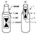
図1は、従来例および本発明の1実施例を示すRFIDタグ付き容器の斜視図である。
RFIDタグ付き液体容器1は、外壁面にRFIDタグ11が貼着され、液体容器1には、導電性の液体2が収納されている。該液体容器1の形態としては、特に限定されるものではなく、例えば、ガラスビン、金属缶、PETボトル、バッグインボックス、ミルクカートンなどの紙製容器などの液体を収納できる容器や包装形態であれば適用できる。収納される導電性液体は、ジュースなどの液体飲料、ビールなどの酒類、シャンプーなどのトイレタリー製品、バッテリー液などの工業用液体などで、導電性を有する液体であれば適用でき、固形分を含んでいても良い。また、収納内容物は、これらに限定されるものではない。
【0007】
なお、固形物はもちろん、サラダオイル・マシン油などの非導電性の液体においては、本発明によらずとも、RFIDタグを容器のどこに貼着しようが、リーダライタとの送受信が可能である。
図1の(A)では、RFIDタグ11が液体容器1に収納されている導電性のある液体2の液面3以下に貼着されており、該RFIDタグ11のアンテナパターンの2面が容器壁面を介して導電性液体と相対しているので、リーダライタと情報の授受ができない。。
【0008】
図1の(B)では本発明の1実施例を示し、RFIDタグ11が、液体容器1に収納されている導電性液体2の液面3部分に貼着されており、該RFIDタグ11のアンテナパターンの1方は、容器壁面を介して導電性液体と相対していないので、リーダライタと情報の授受をすることができる。
【0009】
該RFIDタグが交信に使用する周波数は、UHF−SHF帯(850〜950MHzと、2.4〜5GHz)、HF帯(10〜15MHz)、LF−MF帯(100〜500KHz)がある。電磁誘導方式のRFIDタグでは、導電性液体と相対していても交信が可能であり、本発明では、読み取り距離は比較的短いが、RFIDタグ、リーダライタおよび制御機器を含めてのシステム全体でも安価で、用途面も広い静電結合方式を使用するRFIDタグを用いる。
リーダライタからの呼出し電波に対応して、複数のRFIDタグ11が一斉に応答する場合はデータのコリジョン(衝突)が生じるが、衝突を回避して特定のRFIDタグを順次交信する手法も適用できる。
【0010】
該RFIDタグは、無線で交信ができるが、外観上はきれいというものでもないので、RFIDタグ11を覆って、通常使用している銘板ラベルを貼着するのが好適である。また、該RFIDタグは、銘板ラベルと容器との間に貼着したり、もしくは、銘板ラベルの裏面に形成または銘板ラベルの裏面にラミネートすることで、部外者には該RFIDタグの存在の有無も判らない状態となって、該RFIDタグによる目的とする各種の管理をするためには、より好適である場合が多い。
【0011】
銘板ラベルは、一般的な製品名・セールスポイント・販売者・製造月日などがオフセット印刷・樹脂凸版印刷・グラビア印刷・フレキソ印刷・シルクスクリーン印刷などの印刷で表示された糊貼りラベル・タックラベルなどが適用できる。また、収縮性プラスチックフィルムへ、グラビア・シルクスクリーン印刷などで印刷した筒状のシュリンクラベルやストレッチラベルなど種々のものが適用できる。
【0012】
該糊貼りラベル・タックラベル・シュリンクラベルおよびストレッチラベルの基体としては、特に制限されるものではないが、例えば上質紙・コート紙・含浸紙・合成紙などの紙類、ポリエチレンテレフタレート・ポリプロピレン・ポリ塩化ビニール・エチレン酢酸ビニール共重合体などの合成樹脂類、アルミニウムなどの金属箔類、およびそれらの2層またはそれ以上の積層体などが適用できる。
【0013】
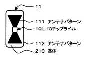
図2は、本発明のRFIDタグを模式で表わす平面図である。
RFIDタグ11は、基体210の表面へアンテナパターン111および112を形成し、該2面のアンテナパターンへ、ICチップラベル10Lの端子部がそれぞれ電気的に接続されている。
【0014】
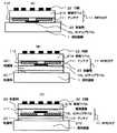
図3は、本発明のRFIDタグを銘板ラベルの裏面へ載置する容器壁面部の断面図である。
本発明のRFIDタグが、銘板ラベルと液体容器との間に固定されている態様を示す。図3(A)は、銘板ラベル21Aの裏面へRFIDタグ11のアンテナパターンが形成されており、銘板ラベル21A自身がRFIDタグ11の基体210を兼ねている。該RFIDタグ11のアンテナパターンおよびICチップラベル面へ粘着剤23を介して液体容器1の外側へ貼着されている。外観的に優れないRFIDタグ11の機能部分は、銘板ラベル21Aへ隠れて、意匠的にも良く、機能的にはなんらの支障もない上に、銘板ラベル21Aは保護層としても働いている。
【0015】
図3(B)は、図3(A)に、さらに保護層221を積層して、該保護層221の両側は粘着剤で固定する。図3(A)の効果とともに、保護層221によって、RFIDタグ11の機能部分は両面ともに保護されることで、保管・流通などの外力にも耐えられて、悪条件での使用にも好適である。
【0016】
図3(C)は、RFIDタグ11のアンテナパターン面を粘着剤23で、銘板ラベル21Bの裏面にラミネートしたものである。銘板ラベル21B自身がRFIDタグ11の基体210を兼ね、さらに、この場合には、銘板ラベル21Bの材料として、耐久性の高いポリエチレンテレフタレート・ポリ塩化ビニールなどのプラスチックシートや合成紙を用いることで、保護層を兼ねるように構成する。このようにすると、RFIDタグ11の機能部分の両側が保護層で覆われた状態になり、さらに耐久性が向上することで、使用できる用途を広げることができる。また、外観的に優れないRFIDタグ11の機能部分は、透明な容器であっても、容器の裏側から覗いても見えないので、意匠的にも良い。
【0017】
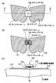
図4は、本発明のRFIDタグの機能部を模式的に表わす平面図および断面図である。
図4(A)は、ICチップラベル10Lをアンテナパターン111、112の双方に接続するように貼着した平面状態、図4(B)は、アンテナパターン111、112からICチップラベル10Lを部分的に剥離した状態を示し、図4(C)は、図4(A)のA−A線に沿う拡大した断面を示す図である。
アンテナパターン111、112の印刷には、導電性インキを使用して、オフセット・グラビア・フレキソ・シルクスクリーン印刷などによって形成する。
導電性インクには、カーボン・黒鉛・アルミ粉・銀紛、あるいはそれらの混合体などをビヒクルに分散したインキを使用する。
【0018】
本発明は、モトローラ社製の製品名「Bistatix」が好適である。
なお、「ICチップラベル」とは、シリコン基板に集積回路またはメモリ、あるいはその双方を設けたICチップを、RFIDタグのアンテナパターン111、112に装着可能にタックラベル化した状態のものを意味し、当該ラベル自体にもICチップに接続した小型のアンテナ部を有する場合もある。
【0019】
一般に、ICチップラベル10Lは、基体210に印刷により形成されたアンテナパターン111、112に対して貼着して使用されるが、図4(B)のように、ICチップラベル10Lにも小型のアンテナパターン121、122が導電性の印刷インキなどにより印刷されている。
【0020】
図4(C)のように、基体210のアンテナパターン111、112とICチップラベル10Lのアンテナパターン121、122とは、異方導電性接着剤117、もしくは非導電性接着剤により結合される。当該接着剤は、あらかじめICチップラベル10Lのアンテナパターン121、122面に塗工されていてタックラベル化している。
【0021】
ICメモリの場合は、1024Bitsで、128文字の記録ができ通常の商品パッケージとして最低限の情報記録には適用できる。数キロビットであれば、2次元バーコード以上の記録が可能である。2次元バーコードと異なり、情報を必要に応じて逐次追加記録しまた書き換えできる利点がある。
【0022】
図5は、従来および本発明のRFIDタグの作用を説明する容器壁面部の断面図である。
図5の(A)は従来例で、RFIDタグ11のアンテナパターン111、112の2面ともが、液体容器1に収納されている導電性液体2の液面3A以下の容器の外壁面に貼着されており、該RFIDタグ11のアンテナパターン111、112のいずれもが容器壁面を介して導電性液体と相対している。
【0023】
該RFIDタグ11は、リーダライタからの呼出し電波に応じて活性化して、RFIDタグ自身のデータを、リーダライタへ送り返すことで、データの交信をしている。しかし、2面のアンテナパターンが、導電性液体に直接接触したり、接近して相対している場合には、2面のアンテナパターンの間が、電気的に導通状態となってしまう。このために、図5(A)に図示したRFIDタグ11は、リーダライタからの呼出し電波に呼応することができなくなって、データの送受信をすることができない。
【0024】
図5の(B)は本発明の1実施例を示し、RFIDタグ11が、液体容器1に収納されている導電性液体2の液面3B部分の外壁面に貼着されており、該RFIDタグ11の一方のアンテナパターン112は、容器壁面を介して導電性液体と相対するが、他方のアンテナパターン111は、容器壁面を介して導電性液体と相対していない。
【0025】
このように、該RFIDタグ11のアンテナパターンの少なくとも1面が、容器壁面を介して導電性液体と相対させないことによって、リーダライタからの呼出し電波に応じて、驚くべきことに、アンテナパターン111、112とICチップによる共振回路を形成することができ、所謂RFIDタグが活性化することで、リーダライタとの送受信ができることを見出した。
呼出し電波で活性化したRFIDタグ11は、静電結合型のアンテナパターン111、112を通じて、リーダライタから電源を供給され、自身のデータを、リーダライタへ送り返すことで交信ができる。
【0026】
図6は、本発明の別の実施態様を示すRFIDタグ付き容器壁面部の断面図である。
RFIDタグ11は、製造・流通および使用過程において結露やアンテナパターンを膨潤させまたは溶解させるような劣悪な環境に晒される場合が想定される時などには、適宜保護層を設けても良い。
図6(A)は、RFIDタグ11の両面に、保護層220、221を設け、図6(B)は、RFIDタグ11の表面に保護層220を設けたものである。また、前述した銘板ラベルが、保護層を兼ねることができれば好適である。
【0027】
該保護層としては、含浸紙・合成紙などの紙類、ポリエチレンテレフタレート・ポリプロピレン・ポリ塩化ビニール・ポリエチレンなどの合成樹脂類、アルミニウムなどの金属箔類、およびそれらの2層またはそれ以上の積層体などが適用できる。これらの保護層基体を、粘着剤を塗布してタックラベル化して貼着したり、熱接着層でヒートシールして、RFIDタグ11へ積層する。
【0028】
図7は、本発明のさらに別の実施態様を示すRFIDタグ付き容器の容器壁面の断面図である。
RFIDタグ11は、容器1を構成する材料が鉄・アルミニウム・ブリキなどの金属材料から構成される場合には、リーダライタとの交信が不安定になることが知られている。図7のRFIDタグ11は、少なくとも片方のアンテナパターンをスペーサ230によって容器本体から距離をとることで、送受信の信頼性が向上して交信が安定する。後述する実施例の如く、1.0mm以上のスペースを設けることで、交信が確実となる。また、金属容器の外壁面に非導電性のものが設けられておれば、この分の厚みもスペーサとして作用する。
【0029】
【実施例】
(比較例1)ラガービール633mlの入ったガラス製ビール大ビンの外壁に、図1(A)のようにモトローラ社製RFIDタグ「Bistatix」を貼着する。
【0030】
(実施例1)モトローラ社製RFIDタグ「Bistatix」を、図1(B)のようにアンテナパターンの一方が容器壁を介して液体を相対しないように貼着する以外は、比較例1と同様とする。
【0031】
(実施例2)オレンジジュース1000mlの入ったゲーベルトップカートンの外壁に、図5(B)のようにモトローラ社製RFIDタグ「Bistatix」を、一方のアンテナパターンが容器壁を介して液体と相対しないように貼着する。ゲーベルトップカートンの材料は、ポリエチレン20μm/ミルクカートン原紙(210g/m2)/ポリエチレン20μm20μm/アルミニウム箔9μm/ポリエチレン40μmの5層積層構成からなっている。
【0032】
(実施例3)モトローラ社製RFIDタグ「Bistatix」の全体を覆って、ポリエチレンテレフタレート16μm/ポリエチレン30μmの2層からなる保護層を、ゲーベルトップカートンの外壁へヒートシールして設けたこと以外は、実施例2と同様とする。
【0033】
(結果)リーダライタから、比較例1、実施例1、実施例2、および実施例3の液体容器へ呼出しをかけたところ、比較例1のRFIDタグとは交信できなかったが、実施例1、実施例2、および実施例3のRFIDタグとは、交信することができた。
【0034】
(比較例2)コーヒ飲料350mlの入ったスチール製缶の外壁に、アンテナパターンの一方が容器壁を介して液体を相対しない図5(A)のように、モトローラ社製RFIDタグ「Bistatix」を貼着する。
【0035】
(比較例3)
モトローラ社製RFIDタグ「Bistatix」を、図7のようにアンテナパターンの一方が容器壁を介して液体を相対しないように、厚さ0.5mmの発泡ポリスチレンからなるスペーサの上にそれぞれ粘着剤で貼着する以外は、比較例2と同様とする。
【0036】
(実施例4)
スペーサとして厚さ1.0mmの発泡ポリスチレンを用いた以外は、比較例3と同様とする。
【0037】
(結果)リーダライタから、比較例2、実施例4のコーヒー入り缶容器へ呼出しをかけたところ、比較例2のRFIDタグとは、1000個のうち11個が交信できなかったが、比較例3のRFIDタグとは、1000個のうち1個が交信できなかったが、実施例4のRFIDタグとは、1000個全数が交信することができた。
【0038】
【発明の効果】
以上説明のように、RFIDタグを、導電性を有する液体を収容する容器外壁へ、アンテナパターンの一方が容器壁を介して液体を相対しないように、貼着することで、リーダライタとの間でデータの送受信ができる。
また、保護層を設けることで、結露などの製造や流通段階での過酷な条件下でも、リーダライタとの間でデータの送受信ができ、かつ、意匠的にも優れる。
さらに、金属缶容器では、容器壁との間にスペースを設けることで、交信の信頼性が向上できる。
【0039】
このように、RFIDタグとリーダライタとの間で無線でデータの送受信をすることで、物品の認識・カウント・追尾・種分けなどを、確実に、無人で、効率良くすることができる。
例えば、工場製品であれば、製造工程を通してその製品を追跡でき、製品の位置や状況を認識できるし、出荷した後でも、製品の履歴が即時知ることができる。また、リーダライタのついたコンベアでの種分け作業であれば、製品の到着やその記録が、コンベアを停止することなくできる。在庫品の管理、出入口にリーダライタを設ければ盗難防止などに、好適である。
【図面の簡単な説明】
【図1】 従来例および本発明の1実施例を示すRFIDタグ付き容器の斜視図である。
【図2】 本発明のRFIDタグを模式で表わす平面図である。
【図3】 本発明のRFIDタグを銘板ラベルの裏面へ載置する容器壁面部の断面図である。
【図4】 本発明のRFIDタグの機能部を模式的に表わす平面図および断面図である。
【図5】 従来および本発明のRFIDタグの作用を説明する容器壁面部の断面図である。
【図6】 本発明の別の実施態様を示すRFIDタグ付き容器壁面部の断面図である。
【図7】 本発明のさらに別の実施態様を示すRFIDタグ付き容器の容器壁面の断面図である。
【符号の説明】
1 液体容器
2 液体
3 液面
10 ICチップ
10L ICチップラベル
11 RFIDタグ
111、112 アンテナパターン
117 異方導電性接着剤
210 基体
220、221 保護層
230 スペーサ[0001]
BACKGROUND OF THE INVENTION
The present invention relates to a liquid container with an RFID tag, and more particularly, with an RFID tag that allows data to be transmitted and received to and from a reader / writer even if it is attached to the outer wall of a container that contains a conductive liquid. It relates to a liquid container.
[0002]
[Prior art]
Conventionally, RFID tags affixed to articles and containers are used to recognize / count / track / classify articles by wirelessly transmitting / receiving data to / from a reader / writer via the antenna pattern of the RFID tag. It is known to do.
However, when the means for transmitting and receiving data to and from the reader / writer is an electrostatic coupling type RFID tag comprising a planar antenna pattern with two surfaces, the two surfaces of the antenna pattern are electrically conductive within the container. If it is attached to the outer wall of the container in contact with the liquid, there is a disadvantage that data cannot be transmitted / received to / from the reader / writer.
[0003]
[Problems to be solved by the invention]
Therefore, in order to solve such a problem, the present invention attaches one of the planar antenna patterns of the RFID tag to the outer wall of the container that is not in contact with the liquid in the container, so that data of the reader / writer can be obtained. The present invention has been completed with the idea that transmission and reception are possible.
[0004]
[Means for Solving the Problems]
In order to solve the above-described problems, thepresent invention provides a liquid container with an RFID tag in which an RFID tag is attached to a container outer wall side of a container thatcontains a conductive liquid, and between the RFID tag and a reader / writer. The means for transmitting and receiving data comprises a capacitively coupled two-plane planar antenna pattern, and when theliquid is unused and the container stands up , one of the antenna patterns is liquid in the container. A liquid container with an RFID tagis provided, whichis attached to an outer wall of a container that is not in contact with the container, and the other pattern of the antenna pattern is attached to an outer wall of the container that is in contact with the liquid in the container. To do .
[0005]
DETAILED DESCRIPTION OF THE INVENTION
The “RFID tag” includes “non-contact IC tag”, “non-contact data carrier”, “wireless IC tag”, “non-contact IC”, “non-contact IC label”, “transponder”, etc. Since it may be expressed by a name, in the present invention, it is expressed as an “RFID tag” as a representative, and includes a name expressed as described above.
[0006]
FIG. 1 is a perspective view of a container with an RFID tag showing a conventional example and one embodiment of the present invention.
The RFID tag-attached
[0007]
Note that not only solid substances but also non-conductive liquids such as salad oil and machine oil can be transmitted to and received from the reader / writer regardless of where the RFID tag is attached, regardless of the present invention.
In FIG. 1A, the
[0008]
FIG. 1B shows an embodiment of the present invention, in which an
[0009]
There are UHF-SHF bands (850 to 950 MHz, 2.4 to 5 GHz), HF bands (10 to 15 MHz), and LF-MF bands (100 to 500 KHz) as frequencies used by the RFID tag for communication. In the electromagnetic induction type RFID tag, communication is possible even if it is opposed to the conductive liquid. In the present invention, the reading distance is relatively short, but the entire system including the RFID tag, the reader / writer, and the control device can also be used. An RFID tag that uses an electrostatic coupling method that is inexpensive and has a wide range of applications is used.
Data collision (collision) occurs when a plurality of
[0010]
Although the RFID tag can communicate wirelessly, it is not clean in appearance, so it is preferable to cover the
[0011]
The nameplate label is a paste label or tack label in which the general product name, sales point, seller, date of manufacture, etc. are displayed by offset printing, resin letterpress printing, gravure printing, flexographic printing, silk screen printing, etc. Etc. are applicable. Moreover, various things, such as a cylindrical shrink label printed on a shrinkable plastic film by gravure and silk screen printing, and a stretch label, are applicable.
[0012]
The base of the glued label, tack label, shrink label and stretch label is not particularly limited. For example, paper such as fine paper, coated paper, impregnated paper, synthetic paper, polyethylene terephthalate, polypropylene, poly Synthetic resins such as vinyl chloride / ethylene vinyl acetate copolymer, metal foils such as aluminum, and laminates of two or more layers thereof can be applied.
[0013]
FIG. 2 is a plan view schematically showing the RFID tag of the present invention.
In the
[0014]
FIG. 3 is a cross-sectional view of the container wall surface portion on which the RFID tag of the present invention is placed on the back surface of the nameplate label.
The RFID tag of this invention shows the aspect currently fixed between the nameplate label and the liquid container. In FIG. 3A, the antenna pattern of the
[0015]
In FIG. 3B, a
[0016]
In FIG. 3C, the antenna pattern surface of the
[0017]
FIG. 4 is a plan view and a cross-sectional view schematically showing a functional part of the RFID tag of the present invention.
4A is a plan view in which the
For the printing of the
As the conductive ink, an ink in which carbon, graphite, aluminum powder, silver powder, or a mixture thereof is dispersed in a vehicle is used.
[0018]
The product name “Bistatix” manufactured by Motorola is suitable for the present invention.
The “IC chip label” means an IC chip in which an integrated circuit and / or a memory is provided on a silicon substrate and is tuck-labeled so that it can be attached to the
[0019]
In general, the
[0020]
As shown in FIG. 4C, the
[0021]
In the case of an IC memory, 128 characters can be recorded at 1024 bits, and it can be applied to the minimum information recording as a normal product package. If it is several kilobits, it is possible to record more than a two-dimensional barcode. Unlike a two-dimensional barcode, there is an advantage that information can be additionally recorded and rewritten sequentially as necessary.
[0022]
FIG. 5 is a cross-sectional view of the wall surface of the container for explaining the operation of the conventional and RFID tags of the present invention.
FIG. 5A shows a conventional example, in which both the
[0023]
The
[0024]
FIG. 5B shows an embodiment of the present invention, in which an
[0025]
As described above, the
The
[0026]
FIG. 6 is a cross-sectional view of a wall surface of a container with an RFID tag showing another embodiment of the present invention.
The
6A shows that the
[0027]
Examples of the protective layer include papers such as impregnated paper and synthetic paper, synthetic resins such as polyethylene terephthalate, polypropylene, polyvinyl chloride, and polyethylene, metal foils such as aluminum, and a laminate of two or more layers thereof. Etc. are applicable. These protective layer bases are laminated to the
[0028]
FIG. 7 is a cross-sectional view of a container wall surface of a container with an RFID tag showing still another embodiment of the present invention.
The
[0029]
【Example】
(Comparative Example 1) An RFID tag “Bistatix” manufactured by Motorola is pasted on the outer wall of a large glass beer bottle containing 633 ml of lager beer as shown in FIG.
[0030]
(Example 1) A RFID tag "Bistatix" manufactured by Motorola, Inc. is the same as Comparative Example 1 except that one of the antenna patterns is stuck so as not to face the liquid through the container wall as shown in FIG. And
[0031]
(Example 2) As shown in FIG. 5B, an RFID tag “Bistatix” manufactured by Motorola is placed on the outer wall of a Gobeltop carton containing 1000 ml of orange juice, and one antenna pattern does not face the liquid through the container wall. Stick like so. The material of the gobel top carton has a five-layer laminated structure of polyethylene 20 μm / milk carton base paper (210 g / m2 ) / polyethylene 20 μm 20 μm / aluminum foil 9 μm / polyethylene 40 μm.
[0032]
(Example 3) Except that the entire RFID tag "Bistatix" manufactured by Motorola Co. was covered and a protective layer consisting of two layers of polyethylene terephthalate 16 μm / polyethylene 30 μm was heat-sealed to the outer wall of the Gobeltop carton, The same as in Example 2.
[0033]
(Result) When the reader / writer called the liquid container of Comparative Example 1, Example 1, Example 2, and Example 3, communication with the RFID tag of Comparative Example 1 was not possible. The RFID tag of Example 2 and Example 3 was able to communicate.
[0034]
(Comparative Example 2) On the outer wall of a steel can containing 350 ml of coffee drink, an RFID tag “Bistatix” manufactured by Motorola is attached to the outer wall of one of the antenna patterns as shown in FIG. Adhere.
[0035]
(Comparative Example 3)
The RFID tag “Bistatix” manufactured by Motorola is applied with an adhesive on a spacer made of polystyrene foam having a thickness of 0.5 mm so that one of the antenna patterns does not face the liquid through the container wall as shown in FIG. It is the same as that of the comparative example 2 except sticking.
[0036]
Example 4
It is the same as that of the comparative example 3 except having used the foamed polystyrene of thickness 1.0mm as a spacer.
[0037]
(Result) When a call was made from the reader / writer to the can container with coffee of Comparative Example 2 and Example 4, 11 RFID tags of Comparative Example 2 could not communicate with 1000 RFID tags. One of 1000 tags could not communicate with the
[0038]
【The invention's effect】
As described above, the RFID tag is attached to the outer wall of the container that stores the conductive liquid so that one of the antenna patterns does not face the liquid through the container wall, so that the reader / writer can be connected. Can send and receive data.
In addition, by providing a protective layer, data can be transmitted to and received from the reader / writer even under severe conditions in the manufacturing and distribution stages such as condensation, and the design is excellent.
Furthermore, in a metal can container, the reliability of communication can be improved by providing a space between the container wall and the container.
[0039]
In this way, by wirelessly transmitting and receiving data between the RFID tag and the reader / writer, the recognition, counting, tracking, and classification of the articles can be reliably performed unmanned and efficiently.
For example, in the case of a factory product, the product can be traced through the manufacturing process, the position and status of the product can be recognized, and the history of the product can be immediately known even after shipment. Further, if the sorting operation is performed on a conveyor with a reader / writer, the arrival and recording of the product can be performed without stopping the conveyor. It is suitable for the management of stocks and the prevention of theft if a reader / writer is provided at the entrance.
[Brief description of the drawings]
FIG. 1 is a perspective view of a container with an RFID tag showing a conventional example and an embodiment of the present invention.
FIG. 2 is a plan view schematically showing the RFID tag of the present invention.
FIG. 3 is a cross-sectional view of a container wall surface portion on which the RFID tag of the present invention is placed on the back surface of the nameplate label.
4A and 4B are a plan view and a cross-sectional view schematically showing a functional part of the RFID tag according to the present invention.
FIG. 5 is a cross-sectional view of a container wall surface for explaining the operation of a conventional and RFID tag of the present invention.
FIG. 6 is a cross-sectional view of a wall surface of a container with an RFID tag showing another embodiment of the present invention.
FIG. 7 is a cross-sectional view of a container wall surface of a container with an RFID tag showing still another embodiment of the present invention.
[Explanation of symbols]
DESCRIPTION OF
Claims (5)
Translated fromJapanesePriority Applications (1)
| Application Number | Priority Date | Filing Date | Title |
|---|---|---|---|
| JP2001061139AJP4712986B2 (en) | 2001-03-06 | 2001-03-06 | Liquid container with RFID tag |
Applications Claiming Priority (1)
| Application Number | Priority Date | Filing Date | Title |
|---|---|---|---|
| JP2001061139AJP4712986B2 (en) | 2001-03-06 | 2001-03-06 | Liquid container with RFID tag |
Publications (2)
| Publication Number | Publication Date |
|---|---|
| JP2002259934A JP2002259934A (en) | 2002-09-13 |
| JP4712986B2true JP4712986B2 (en) | 2011-06-29 |
Family
ID=18920479
Family Applications (1)
| Application Number | Title | Priority Date | Filing Date |
|---|---|---|---|
| JP2001061139AExpired - LifetimeJP4712986B2 (en) | 2001-03-06 | 2001-03-06 | Liquid container with RFID tag |
Country Status (1)
| Country | Link |
|---|---|
| JP (1) | JP4712986B2 (en) |
Families Citing this family (115)
| Publication number | Priority date | Publication date | Assignee | Title |
|---|---|---|---|---|
| JP4219246B2 (en)* | 2003-09-30 | 2009-02-04 | トッパン・フォームズ株式会社 | IC label sheet |
| JP4502621B2 (en)* | 2003-10-21 | 2010-07-14 | シスメックスRa株式会社 | container |
| JP2005204179A (en)* | 2004-01-16 | 2005-07-28 | Tdk Corp | Module substrate with antenna, and radio module using the same |
| JP4826154B2 (en)* | 2004-07-20 | 2011-11-30 | 大日本印刷株式会社 | Package with wireless IC tag |
| US7113125B2 (en) | 2004-12-16 | 2006-09-26 | International Business Machines Corporation | Method for measuring material level in a container using RFID tags |
| JP4500169B2 (en)* | 2005-01-21 | 2010-07-14 | トッパン・フォームズ株式会社 | Moisture detection member and leak detection method |
| JP4899518B2 (en)* | 2005-02-16 | 2012-03-21 | 大日本印刷株式会社 | Package with wireless IC tag |
| JP4872238B2 (en)* | 2005-05-10 | 2012-02-08 | 東洋製罐株式会社 | IC tag compatible plastic material, IC tag and IC tag compatible container |
| JP2007000487A (en)* | 2005-06-27 | 2007-01-11 | Terumo Corp | Infusion bag with ic tag and alarm system for termination of infusion using the same |
| JP4786969B2 (en)* | 2005-08-24 | 2011-10-05 | トッパン・フォームズ株式会社 | Liquid article management method |
| JP4753359B2 (en)* | 2005-09-28 | 2011-08-24 | Necトーキン株式会社 | Wireless tag |
| JP2007181187A (en)* | 2005-11-29 | 2007-07-12 | Semiconductor Energy Lab Co Ltd | Antenna, manufacturing method thereof, semiconductor device having antenna, manufacturing method thereof, and wireless communication system |
| KR101346241B1 (en) | 2005-11-29 | 2013-12-31 | 가부시키가이샤 한도오따이 에네루기 켄큐쇼 | Antenna and manufacturing method thereof, semiconductor device including antenna and manufacturing method thereof, and radio communication system |
| JP4727404B2 (en)* | 2005-12-07 | 2011-07-20 | 株式会社ホロニック | Reading device and article management system |
| US8220717B2 (en) | 2006-01-05 | 2012-07-17 | Hitachi Chemical Co., Ltd. | Tubular container enabling individual identification |
| US7519328B2 (en) | 2006-01-19 | 2009-04-14 | Murata Manufacturing Co., Ltd. | Wireless IC device and component for wireless IC device |
| JP4135770B2 (en) | 2006-04-14 | 2008-08-20 | 株式会社村田製作所 | antenna |
| US9064198B2 (en) | 2006-04-26 | 2015-06-23 | Murata Manufacturing Co., Ltd. | Electromagnetic-coupling-module-attached article |
| JP4040661B2 (en) | 2006-05-01 | 2008-01-30 | 株式会社神戸製鋼所 | RFID tag mounting structure and detection method |
| JP2007311955A (en)* | 2006-05-17 | 2007-11-29 | Dainippon Printing Co Ltd | Non-contact IC tag having a back metal layer |
| CN101467209B (en) | 2006-06-30 | 2012-03-21 | 株式会社村田制作所 | Optical disc |
| WO2008050535A1 (en) | 2006-09-26 | 2008-05-02 | Murata Manufacturing Co., Ltd. | Electromagnetically coupled module and article with electromagnetically coupled module |
| JP4888494B2 (en) | 2007-02-06 | 2012-02-29 | 株式会社村田製作所 | Packaging material with electromagnetic coupling module |
| ATE555453T1 (en) | 2007-04-06 | 2012-05-15 | Murata Manufacturing Co | RADIO IC DEVICE |
| JP4697332B2 (en) | 2007-04-09 | 2011-06-08 | 株式会社村田製作所 | Wireless IC device |
| US8235299B2 (en) | 2007-07-04 | 2012-08-07 | Murata Manufacturing Co., Ltd. | Wireless IC device and component for wireless IC device |
| EP2138962B1 (en) | 2007-04-26 | 2012-01-04 | Murata Manufacturing Co. Ltd. | Wireless ic device |
| WO2008136220A1 (en) | 2007-04-27 | 2008-11-13 | Murata Manufacturing Co., Ltd. | Wireless ic device |
| CN101601056B (en) | 2007-04-27 | 2012-05-23 | 株式会社村田制作所 | Wireless ic device |
| EP2148449B1 (en) | 2007-05-11 | 2012-12-12 | Murata Manufacturing Co., Ltd. | Wireless ic device |
| EP2166617B1 (en) | 2007-07-09 | 2015-09-30 | Murata Manufacturing Co. Ltd. | Wireless ic device |
| EP2166490B1 (en) | 2007-07-17 | 2015-04-01 | Murata Manufacturing Co. Ltd. | Wireless ic device and electronic apparatus |
| US20090021352A1 (en) | 2007-07-18 | 2009-01-22 | Murata Manufacturing Co., Ltd. | Radio frequency ic device and electronic apparatus |
| EP2169594B1 (en) | 2007-07-18 | 2018-03-07 | Murata Manufacturing Co., Ltd. | Wireless ic device and method for manufacturing the same |
| CN102915462B (en) | 2007-07-18 | 2017-03-01 | 株式会社村田制作所 | Wireless IC device |
| JP4462388B2 (en) | 2007-12-20 | 2010-05-12 | 株式会社村田製作所 | Wireless IC device |
| CN103500875B (en) | 2007-12-26 | 2015-12-02 | 株式会社村田制作所 | Antenna assembly and Wireless IC device |
| EP2251934B1 (en) | 2008-03-03 | 2018-05-02 | Murata Manufacturing Co. Ltd. | Wireless ic device and wireless communication system |
| WO2009110382A1 (en) | 2008-03-03 | 2009-09-11 | 株式会社村田製作所 | Composite antenna |
| EP2256861B1 (en) | 2008-03-26 | 2018-12-05 | Murata Manufacturing Co., Ltd. | Radio ic device |
| EP2264831B1 (en) | 2008-04-14 | 2020-05-27 | Murata Manufacturing Co. Ltd. | Radio ic device, electronic device, and method for adjusting resonance frequency of radio ic device |
| EP2284949B1 (en) | 2008-05-21 | 2016-08-03 | Murata Manufacturing Co. Ltd. | Wireless ic device |
| WO2009142068A1 (en) | 2008-05-22 | 2009-11-26 | 株式会社村田製作所 | Wireless ic device and method for manufacturing the same |
| WO2009145007A1 (en) | 2008-05-26 | 2009-12-03 | 株式会社村田製作所 | Wireless ic device system and method for authenticating wireless ic device |
| KR101148534B1 (en) | 2008-05-28 | 2012-05-21 | 가부시키가이샤 무라타 세이사쿠쇼 | Wireless ic device and component for a wireless ic device |
| JP4557186B2 (en) | 2008-06-25 | 2010-10-06 | 株式会社村田製作所 | Wireless IC device and manufacturing method thereof |
| WO2010001987A1 (en) | 2008-07-04 | 2010-01-07 | 株式会社村田製作所 | Wireless ic device |
| EP2320519B1 (en) | 2008-08-19 | 2017-04-12 | Murata Manufacturing Co., Ltd. | Wireless ic device and method for manufacturing same |
| JP5429182B2 (en) | 2008-10-24 | 2014-02-26 | 株式会社村田製作所 | Wireless IC device |
| JP4525869B2 (en) | 2008-10-29 | 2010-08-18 | 株式会社村田製作所 | Wireless IC device |
| JP4605318B2 (en) | 2008-11-17 | 2011-01-05 | 株式会社村田製作所 | Antenna and wireless IC device |
| JP5301252B2 (en)* | 2008-11-28 | 2013-09-25 | サトーホールディングス株式会社 | RFID label and RFID label attaching method |
| CN103500873B (en) | 2009-01-09 | 2016-08-31 | 株式会社村田制作所 | Wireless ic device and wireless ic module |
| CN102204011B (en) | 2009-01-16 | 2013-12-25 | 株式会社村田制作所 | High frequency device and wireless IC device |
| EP2385580B1 (en) | 2009-01-30 | 2014-04-09 | Murata Manufacturing Co., Ltd. | Antenna and wireless ic device |
| JP5510450B2 (en) | 2009-04-14 | 2014-06-04 | 株式会社村田製作所 | Wireless IC device |
| EP2568534A3 (en) | 2009-04-21 | 2014-05-14 | Murata Manufacturing Co., Ltd. | Antenna devie and method of setting resonant frequency of antenna device |
| CN102449846B (en) | 2009-06-03 | 2015-02-04 | 株式会社村田制作所 | Wireless IC device and production method thereof |
| JP5516580B2 (en) | 2009-06-19 | 2014-06-11 | 株式会社村田製作所 | Wireless IC device and method for coupling power feeding circuit and radiation plate |
| JP5182431B2 (en) | 2009-09-28 | 2013-04-17 | 株式会社村田製作所 | Wireless IC device and environmental state detection method using the same |
| JP5201270B2 (en) | 2009-09-30 | 2013-06-05 | 株式会社村田製作所 | Circuit board and manufacturing method thereof |
| JP5304580B2 (en) | 2009-10-02 | 2013-10-02 | 株式会社村田製作所 | Wireless IC device |
| CN102576939B (en) | 2009-10-16 | 2015-11-25 | 株式会社村田制作所 | Antenna and wireless ic device |
| JP5418600B2 (en) | 2009-10-27 | 2014-02-19 | 株式会社村田製作所 | Transceiver and RFID tag reader |
| WO2011055701A1 (en) | 2009-11-04 | 2011-05-12 | 株式会社村田製作所 | Communication terminal and information processing system |
| WO2011055702A1 (en) | 2009-11-04 | 2011-05-12 | 株式会社村田製作所 | Wireless ic tag, reader/writer, and information processing system |
| JP5327334B2 (en) | 2009-11-04 | 2013-10-30 | 株式会社村田製作所 | Communication terminal and information processing system |
| CN104617374B (en) | 2009-11-20 | 2018-04-06 | 株式会社村田制作所 | Mobile communication terminal |
| GB2488450B (en) | 2009-12-24 | 2014-08-20 | Murata Manufacturing Co | Antenna and mobile terminal |
| JP4510133B1 (en)* | 2010-02-19 | 2010-07-21 | 株式会社タケトモ | Packaging container |
| JP5403146B2 (en) | 2010-03-03 | 2014-01-29 | 株式会社村田製作所 | Wireless communication device and wireless communication terminal |
| WO2011108340A1 (en) | 2010-03-03 | 2011-09-09 | 株式会社村田製作所 | Wireless communication module and wireless communication device |
| CN102576940B (en) | 2010-03-12 | 2016-05-04 | 株式会社村田制作所 | Wireless communication devices and metal article processed |
| JP5370581B2 (en) | 2010-03-24 | 2013-12-18 | 株式会社村田製作所 | RFID system |
| WO2011122163A1 (en) | 2010-03-31 | 2011-10-06 | 株式会社村田製作所 | Antenna and wireless communication device |
| JP5170156B2 (en) | 2010-05-14 | 2013-03-27 | 株式会社村田製作所 | Wireless IC device |
| JP5299351B2 (en) | 2010-05-14 | 2013-09-25 | 株式会社村田製作所 | Wireless IC device |
| WO2012005278A1 (en) | 2010-07-08 | 2012-01-12 | 株式会社村田製作所 | Antenna and rfid device |
| GB2537773A (en) | 2010-07-28 | 2016-10-26 | Murata Manufacturing Co | Antenna apparatus and communication terminal instrument |
| JP5423897B2 (en) | 2010-08-10 | 2014-02-19 | 株式会社村田製作所 | Printed wiring board and wireless communication system |
| JP5234071B2 (en) | 2010-09-03 | 2013-07-10 | 株式会社村田製作所 | RFIC module |
| JP5630506B2 (en) | 2010-09-30 | 2014-11-26 | 株式会社村田製作所 | Wireless IC device |
| WO2012050037A1 (en) | 2010-10-12 | 2012-04-19 | 株式会社村田製作所 | Antenna apparatus and communication terminal apparatus |
| CN102971909B (en) | 2010-10-21 | 2014-10-15 | 株式会社村田制作所 | Communication terminal device |
| WO2012093541A1 (en) | 2011-01-05 | 2012-07-12 | 株式会社村田製作所 | Wireless communication device |
| CN103299325B (en) | 2011-01-14 | 2016-03-02 | 株式会社村田制作所 | RFID chip packaging and RFID tags |
| CN103119786B (en) | 2011-02-28 | 2015-07-22 | 株式会社村田制作所 | Wireless communication device |
| WO2012121185A1 (en) | 2011-03-08 | 2012-09-13 | 株式会社村田製作所 | Antenna device and communication terminal apparatus |
| WO2012137717A1 (en) | 2011-04-05 | 2012-10-11 | 株式会社村田製作所 | Wireless communication device |
| WO2012141070A1 (en) | 2011-04-13 | 2012-10-18 | 株式会社村田製作所 | Wireless ic device and wireless communication terminal |
| WO2012157596A1 (en) | 2011-05-16 | 2012-11-22 | 株式会社村田製作所 | Wireless ic device |
| JP5466204B2 (en)* | 2011-06-23 | 2014-04-09 | 富士通フロンテック株式会社 | Reading apparatus and reading method |
| KR101338173B1 (en) | 2011-07-14 | 2013-12-06 | 가부시키가이샤 무라타 세이사쿠쇼 | Wireless communication device |
| WO2013011856A1 (en) | 2011-07-15 | 2013-01-24 | 株式会社村田製作所 | Wireless communication device |
| CN204189963U (en) | 2011-07-19 | 2015-03-04 | 株式会社村田制作所 | Antenna assembly and communication terminal |
| WO2013035821A1 (en) | 2011-09-09 | 2013-03-14 | 株式会社村田製作所 | Antenna device and wireless device |
| JP5344108B1 (en) | 2011-12-01 | 2013-11-20 | 株式会社村田製作所 | Wireless IC device and manufacturing method thereof |
| EP2688145A1 (en) | 2012-01-30 | 2014-01-22 | Murata Manufacturing Co., Ltd. | Wireless ic device |
| JP5464307B2 (en) | 2012-02-24 | 2014-04-09 | 株式会社村田製作所 | ANTENNA DEVICE AND WIRELESS COMMUNICATION DEVICE |
| CN104487985B (en) | 2012-04-13 | 2020-06-26 | 株式会社村田制作所 | RFID tag inspection method and inspection device |
| KR20150022992A (en)* | 2012-06-13 | 2015-03-04 | 도판 인사츠 가부시키가이샤 | Non-contact ic label and nameplate |
| WO2016043173A1 (en)* | 2014-09-17 | 2016-03-24 | 株式会社 村田製作所 | Rfid device and object with rfid device |
| WO2018131527A1 (en)* | 2017-01-12 | 2018-07-19 | 旭硝子株式会社 | Glass casing and communication device |
| JP7097159B2 (en)* | 2017-07-03 | 2022-07-07 | 高砂熱学工業株式会社 | Registration program, mobile terminal and registration method |
| CN107611499A (en)* | 2017-07-27 | 2018-01-19 | 山东圣阳电源股份有限公司 | A kind of battery and its assembly technology |
| JP2019163071A (en)* | 2018-03-20 | 2019-09-26 | 凸版印刷株式会社 | Bottle attached with ic tag label and ic tag label |
| JP7155751B2 (en)* | 2018-08-23 | 2022-10-19 | 大日本印刷株式会社 | RF tag label |
| JP7275532B2 (en)* | 2018-11-02 | 2023-05-18 | 大日本印刷株式会社 | RF tag labels and articles with RF tag labels |
| US12039394B2 (en) | 2019-07-19 | 2024-07-16 | Daio Paper Corporation | RFID tag, pet bottle, and antenna |
| JP7340175B2 (en)* | 2019-07-19 | 2023-09-07 | 大王製紙株式会社 | RFID tags, plastic bottles, and antennas |
| JP7467845B2 (en)* | 2019-09-04 | 2024-04-16 | 大日本印刷株式会社 | RF tag labels and products to which they are affixed |
| JP2021189447A (en)* | 2020-05-28 | 2021-12-13 | サトーホールディングス株式会社 | How to use RFID labels and RFID labels |
| JP7243931B2 (en)* | 2020-11-30 | 2023-03-22 | 株式会社村田製作所 | CONTAINER WITH RFID MODULE AND METHOD FOR MANUFACTURING CONTAINER WITH RFID MODULE |
| WO2023209947A1 (en)* | 2022-04-28 | 2023-11-02 | 立山科学株式会社 | Rf tag |
| JP7590778B2 (en)* | 2022-09-15 | 2024-11-27 | 明 渡辺 | RFID tags, passive RFID tag sensors, spacers for RFID tags, and spacers for auxiliary antennas |
Family Cites Families (5)
| Publication number | Priority date | Publication date | Assignee | Title |
|---|---|---|---|---|
| JPH09330388A (en)* | 1996-06-10 | 1997-12-22 | Denso Corp | Ic card |
| JPH10297640A (en)* | 1997-04-25 | 1998-11-10 | Yoshino Kogyosho Co Ltd | Article packaging container |
| JPH11240523A (en)* | 1998-02-27 | 1999-09-07 | Matsushita Electric Works Ltd | Fitting method of discrimination label |
| KR100437007B1 (en)* | 1998-09-11 | 2004-06-23 | 모토로라 인코포레이티드 | Radio frequency identification tag apparatus and related method |
| JP2001005931A (en)* | 1999-06-18 | 2001-01-12 | Tohken Co Ltd | Barcode seal having RFID function and method for providing barcode label with RFID function |
- 2001
- 2001-03-06JPJP2001061139Apatent/JP4712986B2/ennot_activeExpired - Lifetime
Also Published As
| Publication number | Publication date |
|---|---|
| JP2002259934A (en) | 2002-09-13 |
Similar Documents
| Publication | Publication Date | Title |
|---|---|---|
| JP4712986B2 (en) | Liquid container with RFID tag | |
| EP3184456B1 (en) | Closure assembly with radio frequency identification tag | |
| JP3984458B2 (en) | Manufacturing method of package with IC tag | |
| EP1301901B1 (en) | Wireless communication device and method | |
| KR101149633B1 (en) | Seal with ic tag and method of attaching the same | |
| CN101390111B (en) | Base material for RFID tags suitable for metal materials | |
| US20120217244A1 (en) | Container seal with radio frequency identification tag, and method of making same | |
| KR20070049105A (en) | How to attach a label with RFID tag on an article | |
| AU2011239611A1 (en) | Container seal with radio frequency identification tag, and method of making same | |
| CN101452622A (en) | Rfid seal tag | |
| KR20070007165A (en) | Deactivating a data tag for user privacy or tamper-evident packaging | |
| US20060103532A1 (en) | Electromagnetic pathways to eliminate RFID limitations | |
| JP4220184B2 (en) | Cap seal with IC tag | |
| JP2006227670A (en) | Rfid adhesive label | |
| WO2020124082A1 (en) | Merchandise attachment with rfid transponder | |
| CN113168549A (en) | Method, system and apparatus for forming and placing radio frequency identification tags | |
| JP2006003497A (en) | Label with ic tag and container with ic tag | |
| CN206946528U (en) | A kind of frangible RFID antifalsification labels | |
| JP2002321725A (en) | Data carrier mounted carrier and radio wave receiving method thereof | |
| US20110241834A1 (en) | Intrinsic Consumer Warnings and Pinch Peel Plates for RFID Inlays | |
| JP4872238B2 (en) | IC tag compatible plastic material, IC tag and IC tag compatible container | |
| CN104349990A (en) | Container closure with radio frequency identification tag and method of manufacture | |
| CN208731550U (en) | Storage Containers for Items with IC Labels | |
| CN210681697U (en) | Cap and bottle comprising same | |
| KR101111180B1 (en) | Wrapping sheets bonded rfid tag |
Legal Events
| Date | Code | Title | Description |
|---|---|---|---|
| A621 | Written request for application examination | Free format text:JAPANESE INTERMEDIATE CODE: A621 Effective date:20071121 | |
| A977 | Report on retrieval | Free format text:JAPANESE INTERMEDIATE CODE: A971007 Effective date:20101028 | |
| A131 | Notification of reasons for refusal | Free format text:JAPANESE INTERMEDIATE CODE: A131 Effective date:20101102 | |
| A521 | Request for written amendment filed | Free format text:JAPANESE INTERMEDIATE CODE: A523 Effective date:20101227 | |
| A01 | Written decision to grant a patent or to grant a registration (utility model) | Free format text:JAPANESE INTERMEDIATE CODE: A01 Effective date:20110301 | |
| A61 | First payment of annual fees (during grant procedure) | Free format text:JAPANESE INTERMEDIATE CODE: A61 Effective date:20110324 |