JP4711669B2 - Image forming apparatus - Google Patents
Image forming apparatusDownload PDFInfo
- Publication number
- JP4711669B2 JP4711669B2JP2004357833AJP2004357833AJP4711669B2JP 4711669 B2JP4711669 B2JP 4711669B2JP 2004357833 AJP2004357833 AJP 2004357833AJP 2004357833 AJP2004357833 AJP 2004357833AJP 4711669 B2JP4711669 B2JP 4711669B2
- Authority
- JP
- Japan
- Prior art keywords
- photosensitive drum
- shaft
- outer ring
- image forming
- forming apparatus
- Prior art date
- Legal status (The legal status is an assumption and is not a legal conclusion. Google has not performed a legal analysis and makes no representation as to the accuracy of the status listed.)
- Expired - Fee Related
Links
Images


Landscapes
- Discharging, Photosensitive Material Shape In Electrophotography (AREA)
- Electrophotography Configuration And Component (AREA)
Description
Translated fromJapaneseこの発明は、複写機やレーザビームプリンタ(LBP)の如き画像形成装置に関する。 The present invention relates to an image forming apparatus such as a copying machine or a laser beam printer (LBP).
一方向に回転される感光ドラムの外周囲に帯電器、露光手段、現像器および転写帯電器を設け、上記帯電器によって感光ドラムの外周全体を一様に帯電したのち、露光手段により画像情報に基づく画像光を露光して静電潜像を形成し、現像器からその静電潜像にトナーを供給してトナー像を形成し、そのトナー像を転写帯電器によって感光ドラムの周速と同速度で搬送される転写材上に転写するようにした画像形成装置は従来から知られている。 A charger, an exposure unit, a developing unit, and a transfer charger are provided around the outer periphery of the photosensitive drum that is rotated in one direction. After the entire outer periphery of the photosensitive drum is uniformly charged by the charger, image information is obtained by the exposure unit. Image light is exposed to form an electrostatic latent image, and toner is supplied from the developing unit to the electrostatic latent image to form a toner image. The toner image is transferred to the photosensitive drum at the same peripheral speed as the transfer charger. 2. Description of the Related Art Image forming apparatuses that transfer onto a transfer material conveyed at a speed are conventionally known.
単色の画像形成装置においては、感光ドラム、帯電器、露光手段、現像器および転写帯電器から成る1組の画像形成ユニットによって画像を形成し、一方、フルカラーの画像形成装置においては、4組の画像形成ユニットを転写材の搬送方向にタンデムに配置し、それぞれの画像形成ユニットによってイエロー、マゼンタ、シアン、ブラックの各色のトナー像を形成し、これらのトナー像を転写材上に転写してカラー画像を形成するようにしている。 In a monochromatic image forming apparatus, an image is formed by a set of image forming units including a photosensitive drum, a charger, an exposure unit, a developing unit, and a transfer charger. On the other hand, in a full-color image forming apparatus, four sets of images are formed. The image forming units are arranged in tandem in the transfer material conveyance direction, and each image forming unit forms a toner image of each color of yellow, magenta, cyan, and black, and these toner images are transferred onto the transfer material to form a color. An image is formed.
単色およびフルカラーの画像形成装置においては、感光ドラムの回転によって画像を形成するため、感光ドラムの1回転中における回転速度にムラがあると、露光手段による露光時に感光ドラム上の静電潜像に伸縮が生じると共に、転写材に対するトナー像の転写時に画像に伸縮が生じ、これ等が一体となって画像ムラを生じさせ、高品質の画像を形成することができない。したがって、感光ドラムは常に等速度で回転させる必要がある。 In single-color and full-color image forming apparatuses, an image is formed by the rotation of the photosensitive drum. Therefore, if there is uneven rotation speed during one rotation of the photosensitive drum, the electrostatic latent image on the photosensitive drum is exposed during exposure by the exposure unit. In addition to the expansion and contraction, the image expands and contracts when the toner image is transferred to the transfer material, and these cause an image unevenness and cannot form a high quality image. Therefore, it is necessary to always rotate the photosensitive drum at a constant speed.
感光ドラムの駆動に際し、その感光ドラムのドラム軸にモータの回転軸を直結し、上記モータの駆動によって感光ドラムを回転させるようにしたものが知られているが、感光ドラムの支持およびモータの取付けに際して誤差が生じるため、感光ドラムのドラム軸とモータの回転軸とを同一軸上に配置することはきわめて困難であり、上記ドラム軸と回転軸の相互間に芯ずれや傾きが生じた場合に感光ドラムを一定の速度で回転させることができず、品質の高い画像を形成することができない。 It is known that when a photosensitive drum is driven, a rotating shaft of a motor is directly connected to the drum shaft of the photosensitive drum, and the photosensitive drum is rotated by driving the motor. In this case, it is extremely difficult to arrange the drum shaft of the photosensitive drum and the rotation shaft of the motor on the same axis, and when the misalignment or inclination occurs between the drum shaft and the rotation shaft. The photosensitive drum cannot be rotated at a constant speed, and a high-quality image cannot be formed.
そのような問題点を解決するため、特許文献1に記載された画像形成装置においては、感光ドラムのドラム軸とモータの回転軸とを自在継手で連結し、かつ、感光ドラムの露光位置と転写位置を180°の位置に配置して、感光ドラムの回転速度ムラによる画像の伸縮を感光ドラム上の露光位置と転写位置における画像の伸縮により相殺し、転写材上での画像の伸縮を防止するようにしている。
ところで、上記特許文献1に記載された画像形成装置においては、自在継手が不等速形の自在継手であるため、感光ドラムを等速度で回転させることができず、感光ドラムの露光位置と転写位置を180°の位置としたとしても、組立て誤差や感光ドラムの傾き、撓み等で180°の位置にずれが生じて画像の伸縮を完全に相殺することができず、品質の高い画像を形成することができない。 By the way, in the image forming apparatus described in
また、上記不等速形自在継手を用いた画像形成装置においては、自在継手がドラム軸とモータの回転軸とが相対的に傾きのある場合には使用可能であるが、上記両軸にずれがあってほぼ平行に配置されている場合には、ドラム軸とモータの回転軸の対向部間に中間軸を設け、その中間軸とドラム軸との間、および中間軸とモータの回転軸の間に自在継手を組込む必要が生じ、ドラム軸とモータの回転軸の間が長くなると共に、2個の自在継手が必要であるため、コストが高くなるという問題が生じる。 In the image forming apparatus using the inconstant-velocity universal joint, the universal joint can be used when the drum shaft and the rotation shaft of the motor are relatively inclined. If there is an approximately parallel arrangement, an intermediate shaft is provided between the opposing portions of the drum shaft and the motor rotation shaft, between the intermediate shaft and the drum shaft, and between the intermediate shaft and the motor rotation shaft. There is a need to incorporate a universal joint between the drum shaft and the rotating shaft of the motor, and two universal joints are required, resulting in an increase in cost.
この発明の課題は、平行に配置された感光ドラムのドラム軸とモータの回転軸の相互間に軸心にずれがある場合でも、モータの回転軸の回転を感光ドラムに常に等速度で伝達し得るようにして高品質の画像を形成することができるようにした画像形成装置を提供することである。 The object of the present invention is to always transmit the rotation of the rotating shaft of the motor to the photosensitive drum at a constant speed even when there is a shift in the axis between the drum shaft of the photosensitive drum and the rotating shaft of the motor arranged in parallel. It is an object of the present invention to provide an image forming apparatus capable of forming a high-quality image.
上記の課題を解決するために、この発明においては、感光ドラムと、その感光ドラムを回転駆動する駆動手段と、前記感光ドラム上に静電潜像を形成する露光手段と、前記感光ドラム上の静電潜像にトナーを供給してトナー像を形成する現像手段と、感光ドラムの周速と同速度で搬送される転写材上に前記トナー像を転写する転写手段とから成り、前記感光ドラムのドラム軸と駆動手段の駆動軸とを軸継手で連結した画像形成装置において、前記軸継手が、一端が開口する環状空間を有し、その環状空間の開口端が向き合うように対向配置された2個の外輪と、各外輪の環状空間内に挿入されるケージ部を両端に有する継手部材とを有し、前記各外輪の環状空間内における外壁面と内壁面の少なくとも一方に軸方向に延びる3本のトラック溝を周方向に120°の間隔をおいて形成し、各トラック溝に沿って転動可能なボールを前記継手部材の各ケージ部で保持した等速ジョイントから成る構成を採用したのである。 In order to solve the above-described problems, in the present invention, a photosensitive drum, a driving unit that rotationally drives the photosensitive drum, an exposure unit that forms an electrostatic latent image on the photosensitive drum, and a photosensitive drum The photosensitive drum comprises: developing means for supplying toner to the electrostatic latent image to form a toner image; and transfer means for transferring the toner image onto a transfer material conveyed at the same speed as the peripheral speed of the photosensitive drum. In the image forming apparatus in which the drum shaft and the drive shaft of the driving means are connected by a shaft joint, the shaft joint has an annular space with one end opened, and the opposite ends are arranged so that the open ends of the annular space face each other. Two outer rings and a joint member having both ends of a cage portion inserted into the annular space of each outer ring, and extending in the axial direction to at least one of the outer wall surface and the inner wall surface in the annular space of each
ここで、等速ジョイントの外輪を合成樹脂の成形品とすることによって、等速ジョイントを無潤滑化することができると共に、等速ジョイントの軽量化を図ることができる。 Here, by using the outer ring of the constant velocity joint as a synthetic resin molded product, the constant velocity joint can be made non-lubricated and the constant velocity joint can be reduced in weight.
また、等速ジョイントの継手部材を合成樹脂の成形品とすることによって、等速ジョイントのより軽量化を図ることができる。 Further, the constant velocity joint can be further reduced in weight by using a synthetic resin as the joint member of the constant velocity joint.
合成樹脂として射出成形可能な合成樹脂とすることにより、外輪およびケージを容易に成形することができる。また、潤滑性樹脂を採用することによって、ボール転動面の潤滑性をより高めることができるため、動作音のより小さい等速ジョイントを得ることができる。 By using a synthetic resin that can be injection-molded as the synthetic resin, the outer ring and the cage can be easily molded. Further, by adopting the lubricating resin, it is possible to further improve the lubricity of the ball rolling surface, so that it is possible to obtain a constant velocity joint with a smaller operating noise.
さらに、等速ジョイントのボールに予圧を付与することによって、周方向ガタのない等速性に優れた等速ジョイントを得ることができ、駆動手段の作動によって、感光ドラムをより効果的に等速回転させることができる。 Furthermore, by applying a preload to the balls of the constant velocity joint, it is possible to obtain a constant velocity joint that is free of circumferential play and is excellent in constant velocity. Can be rotated.
また、等速ジョイントの外輪を隣接するトラック溝間で分割し、トラック溝を有する3つの弾性片を形成することにより、等速ジョイントに過大なトルクが負荷されると、各弾性片が外輪の径方向に弾性変形して外輪とケージの相互間で回転トルクの伝達を遮断することができる。このため、等速ジョイントにトルクリミッタとしての機能を付加することができ、破損することが少ない等速ジョイントを得ることができる。 In addition, by dividing the outer ring of the constant velocity joint between adjacent track grooves and forming three elastic pieces having track grooves, when excessive torque is applied to the constant velocity joint, each elastic piece It is possible to block the transmission of rotational torque between the outer ring and the cage by elastic deformation in the radial direction. For this reason, a function as a torque limiter can be added to the constant velocity joint, and a constant velocity joint that is less likely to be damaged can be obtained.
上記のように、感光ドラムのドラム軸と駆動手段の駆動軸とを2個の外輪を有する等速ジョイントで連結したことにより、上記駆動手段の駆動軸と感光ドラムのドラム軸の相互に芯ずれや傾きがあっても、あるいは上記両軸にずれがあってほぼ平行に配置されている場合においても感光ドラムを速度ムラを発生させずに等速回転させることができる。 As described above, since the drum shaft of the photosensitive drum and the drive shaft of the driving means are connected by the constant velocity joint having two outer rings, the drive shaft of the driving means and the drum shaft of the photosensitive drum are misaligned. Even when there is a tilt or when there is a deviation between the two axes, the photosensitive drum can be rotated at a constant speed without causing uneven speed.
このため、露光手段によって形成される静電潜像に伸縮が生じたり、感光ドラム上のトナー像が転写材に転写される際に画像に伸縮が生じるのを防止することができ、きわめて高品質の画像を形成することができる。 For this reason, it is possible to prevent the electrostatic latent image formed by the exposure means from expanding and contracting, and the image from expanding and contracting when the toner image on the photosensitive drum is transferred to the transfer material. Images can be formed.
また、等速ジョイントの外輪およびケージが金属から成る場合はグリース潤滑を必要とし、画像形成装置のメンテナンスが困難であって、グリースの漏洩により転写材が汚される懸念があるが、上記外輪およびケージを合成樹脂の成形品としたことにより、グリース潤滑を不要とすることができる。その結果、画像形成装置のメンテナンスの容易化を図ることができると共に、転写材が汚されるという不都合の発生を皆無とすることができる。 Further, when the outer ring and the cage of the constant velocity joint are made of metal, grease lubrication is required, and maintenance of the image forming apparatus is difficult, and there is a concern that the transfer material may be soiled due to leakage of the grease. By using a synthetic resin molded product, grease lubrication can be dispensed with. As a result, the maintenance of the image forming apparatus can be facilitated, and the inconvenience that the transfer material is contaminated can be eliminated.
また、トルク伝達時の動作音の小さな画像形成装置を得ることができる。 Further, it is possible to obtain an image forming apparatus with a small operating sound during torque transmission.
以下、この発明の実施形態を図面に基づいて説明する。図1は単色の画像形成装置を示す。この画像形成装置は、感光ドラム1を有している。感光ドラム1は、図2に示す駆動手段としての駆動モータ2によって図1の矢印で示す方向に回転され、その感光ドラム1の周囲に、帯電器3、露光手段4、現像手段としての現像器5、転写手段としての転写帯電器6およびクリーニング器7が感光ドラム1の回転方向に順に設けられている。 Embodiments of the present invention will be described below with reference to the drawings. FIG. 1 shows a monochromatic image forming apparatus. This image forming apparatus has a
上記の構成から成る画像形成装置は、感光ドラム1の回転時に帯電器3によって感光ドラム1の外周全体を一様に帯電したのち、露光手段4により画像情報に基づく画像光を露光して静電潜像を形成し、現像器5からその静電潜像上にトナーを供給してトナー像を形成し、そのトナー像を転写帯電器6により感光ドラム1の周速と同速度で搬送される転写材A上に転写して、転写材Aに画像を形成するようにしている。また、転写後、感光ドラム1の周面に残る残留トナーをクリーニング器7によって取り除くようにしている。 In the image forming apparatus having the above-described configuration, the entire outer periphery of the
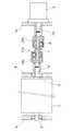
図2に示すように、感光ドラム1は、両端にドラム軸1aを有し、そのドラム軸1aが一対のサイドフレーム8に軸受9を介して回転自在に支持され、一方、感光ドラム1を回転駆動する駆動モータ2はケーシング10に取付けられて感光ドラム1と軸方向で対向する配置とされている。 As shown in FIG. 2, the
駆動モータ2の駆動軸としての回転軸2aと感光ドラム1のドラム軸1aとは等速ジョイントCVJを介して連結されている。 The rotating
図3および図4に示すように、等速ジョイントCVJは、2個の外輪OR1、OR2と、その外輪OR1、OR2間に設けられた継手部材Jと、その継手部材Jと外輪OR1、OR2の相互間で回転トルクを伝達するボールBとから成る。As shown in FIGS. 3 and 4, the constant velocity joint CVJ includes two outer rings OR1 and OR2 , a joint member J provided between the outer rings OR1 and OR2 , the joint member J, and the outer ring. It consists of a ball B that transmits rotational torque between OR1 and OR2 .
外輪OR1、OR2は、一端が開口するカップ部11を有し、そのカップ部11の閉塞端に接続軸12が一体に設けられている。また、カップ部11内には中心軸上にガイド軸13が設けられ、そのガイド軸13とカップ部11間に環状空間14が形成され、上記環状空間14の外壁面を形成するカップ部11の内周面と環状空間14の内壁面を形成するガイド軸13の外周面に軸方向に延びる3本のトラック溝15、16が周方向に120°の間隔をおいて設けられている。The outer rings OR1 and OR2 each have a
なお、実施の形態では、環状空間14の外壁面と内壁面のそれぞれにトラック溝15、16を形成したが、上記外壁面と内壁面の一方にトラック溝を設けるようにしてもよい。 In the embodiment, the
上記2個の外輪OR1、OR2は、カップ部11の開口端が向き合うよう対向配置され、そのカップ部11間に前記継手部材Jが組込まれている。The two outer rings OR1 and OR2 are disposed to face each other so that the open ends of the
継手部材Jは、外輪OR1、OR2の環状空間14内に挿入されるケージ部21を両端に有し、そのケージ部21は外輪OR1、OR2の開口部に取付けられた止め輪17によって抜け止めされている。ケージ部21には各外輪OR1、OR2のトラック溝15、16のそれぞれに対応してポケット22が形成され、各ポケット22内に前記ボールBが組込まれている。ボールBのそれぞれは、各トラック溝15、16に沿って転動自在とされている。The joint member J has
上記のように、対向配置された2個の外輪OR1、OR2のトラック溝15、16に沿って転動可能なボールBを外輪OR1、OR2間に組込まれた継手部材Jのケージ部21で保持することにより、2個の外輪OR1、OR2の相互に軸心にずれがあると、継手部材Jが傾斜して上記軸心のずれを吸収し、2個の外輪OR1、OR2の相互間で等速度でトルク伝達することができる等速ジョイントCVJを得ることができる。As described above, the cage B of the joint member J in which the ball B which can roll along the
したがって、一方の外輪の接続軸12を駆動モータ2の回転軸2aに、他方の外輪の接続軸2を感光ドラム1のドラム軸1aに接続することにより、回転軸2aとドラム軸1aの相互に軸心にずれがある場合でも駆動モータ2の回転を感光ドラム1に等速度で伝達することができる。 Therefore, by connecting the connecting
外輪OR1、OR2および継手部材Jは合成樹脂の成形品から成って、その継手部材Jの両ゲージ部21、21は一体品となっている。合成樹脂としては射出成形可能な合成樹脂が望ましい。射出成形可能な樹脂であれば、熱可塑性樹脂、熱硬化性樹脂のいずれでもよい。The outer rings OR1 and OR2 and the joint member J are made of a synthetic resin molded product, and both gauge
射出成形可能な樹脂には結晶性樹脂、非結晶性樹脂があり、いずれの樹脂を使用してもよいが、非結晶性樹脂は靱性が低く、許容量以上のトルクがかかった場合急激な破壊が生じるため、結晶性樹脂を用いるのが好ましい。 There are two types of resin that can be injection-molded: crystalline resin and non-crystalline resin. Either resin can be used, but non-crystalline resin has low toughness and breaks rapidly when torque exceeds the allowable amount. Therefore, it is preferable to use a crystalline resin.
好ましい合成樹脂として、潤滑特性の高い合成樹脂、例えば、ポリアセタール樹脂(POM)、ナイロン樹脂、PFAやFEP、ETFE等の射出成形可能なフッ素樹脂、射出成形可能なポリイミド樹脂、ポリフェニレンスルフィド樹脂(PPS)、全芳香族ポリエステル樹脂、ポリエーテルエーテルケトン系樹脂(PEEK)、ポリアミドイミド樹脂等を挙げることができる。 Preferred synthetic resins include synthetic resins with high lubricating properties, such as polyacetal resins (POM), nylon resins, fluoroplastics such as PFA, FEP, and ETFE, injection moldable polyimide resins, and polyphenylene sulfide resins (PPS). And wholly aromatic polyester resins, polyetheretherketone resins (PEEK), polyamideimide resins, and the like.
これらの各樹脂は単独で使用してもよく、2種類以上混合したポリマーアロイであってもよい。あるいは、上記以外の潤滑特性の低い合成樹脂に上記の合成樹脂を配合したポリマーアロイであってもよい。 Each of these resins may be used alone or a polymer alloy in which two or more kinds are mixed. Or the polymer alloy which mix | blended said synthetic resin with the synthetic resin with low lubrication characteristics other than the above may be sufficient.
また、潤滑特性の低い合成樹脂であっても、固体潤滑剤や潤滑油を添加することで潤滑特性を高めることにより使用可能である。 Moreover, even a synthetic resin having low lubricating properties can be used by enhancing the lubricating properties by adding a solid lubricant or lubricating oil.
固体潤滑剤として、ポリテトラフルオロエチレン、黒鉛、二流化モリブデン等を挙げることができる。 Examples of the solid lubricant include polytetrafluoroethylene, graphite, and molybdenum disulfide.
また、合成樹脂にガラス繊維、炭素繊維、各種鉱物性繊維(ウィスカー)を配合して強度を高めてもよく、固体潤滑剤等と併用してもよい。 Further, glass fiber, carbon fiber, various mineral fibers (whiskers) may be added to the synthetic resin to increase the strength, or may be used in combination with a solid lubricant or the like.
最も使用に適した材料は、POM、ナイロン樹脂、PPS、PEEKである。ナイロン樹脂はナイロン6、ナイロン66、ナイロン610、ナイロン612、ナイロン11、ナイロン12、ナイロン46、分子鎖中に芳香族環を有する半芳香族ナイロン等のいずれでもよい。POM、ナイロン樹脂、PPSは、耐熱性、潤滑性に優れて比較的安価であるため、コストパフォーマンスの優れた等速ジョイントを得ることができる。 The most suitable materials for use are POM, nylon resin, PPS, PEEK. The nylon resin may be
また、PEEKは補強材や潤滑剤を配合しなくても機械的強度や潤滑性に優れるため、高機能な等速ジョイントを得ることができる。 Moreover, PEEK is excellent in mechanical strength and lubricity even if a reinforcing material and a lubricant are not blended, so that a high-performance constant velocity joint can be obtained.
さらに、外輪OR1、OR2および継手部材Jを合成樹脂の成形品とすることによって、軽量であって、トルク伝達時の動作音の小さな等速ジョイントを得ることができると共に、グリース潤滑を不要とすることができる。Furthermore, by using the outer rings OR1 and OR2 and the joint member J as molded parts of synthetic resin, it is possible to obtain a constant velocity joint that is light in weight and has a low operating noise during torque transmission, and does not require grease lubrication. It can be.
ボールBは軸受鋼、ステンレススチール、セラミックス、合成樹脂等のボールBを使用することができるが、ステンレススチール、セラミックス、合成樹脂にすることで無潤滑でも錆の心配が不要で好ましい。合成樹脂であればさらに軽量となるため好ましい。 Ball B can be made of bearing steel, stainless steel, ceramics, synthetic resin, or the like, but stainless steel, ceramics, or synthetic resin is preferable because there is no need to worry about rust even without lubrication. A synthetic resin is preferable because it is lighter.
また、外輪OR1、OR2においては、カップ部11とガイド軸13を合成樹脂で一体に成形したが、ガイド軸13をセラミックスや鉄鋼、ステンレススチール、アルミニウム合金等で形成して、カップ部11に結合するようにしてもよい。In the outer rings OR1 and OR2 , the
実施の形態で示すように、感光ドラム1のドラム軸1aと駆動モータ2の回転軸2aとを等速ジョイントCVJで連結することにより、感光ドラム1のドラム軸1aと駆動モータ2の回転軸2aの相互に芯ずれや傾きがあっても感光ドラム1を速度ムラを発生させることなく等速回転させることができる。このため、露光手段4によって感光ドラム1上に形成される静電潜像に伸縮が生じたり、感光ドラム1上のトナー像が転写帯電器6により転写材Aに転写される際に画像に伸縮が生じるのを防止することができる。 As shown in the embodiment, the
したがって、高品質の画像を形成することができると共に、露光手段4と転写帯電器6を180°の位置に設ける必要がないため、設計の自由度を高めることができる。 Therefore, it is possible to form a high-quality image, and it is not necessary to provide the
また、等速ジョイントCVJの外輪OR1、OR2および継手部材Jを合成樹脂の成形品としたことにより、グリース潤滑を不要とすることができる。Further, since the outer rings OR1 and OR2 of the constant velocity joint CVJ and the joint member J are molded products of synthetic resin, grease lubrication can be eliminated.
このため、画像形成装置のメンテナンスの容易化を図ることができると共に、グリースの飛散もないため、転写材Aが汚されるという不都合の発生を皆無とすることができる。 For this reason, the maintenance of the image forming apparatus can be facilitated and there is no scattering of grease, so that there is no inconvenience that the transfer material A is soiled.
また、外輪OR1、OR2および継手部材Jを合成樹脂の成形品とすることでトルク伝達時の動作音の小さな等速ジョイントCVJを得ることができる。Further, by using the outer rings OR1 , OR2 and the joint member J as a synthetic resin molded product, a constant velocity joint CVJ having a low operating noise during torque transmission can be obtained.
図3および図4に示す等速ジョイントCVJのように、外輪OR1、OR2を合成樹脂の成形品とすることにより、その外輪OR1、OR2の弾性を利用してボールBに予圧を付与することができる。Like the constant velocity joint CVJ shown in FIG. 3 and FIG. 4, the outer rings OR1 and OR2 are formed of a synthetic resin, so that the ball B is preloaded using the elasticity of the outer rings OR1 and OR2. Can be granted.
具体的には、カップ部11の内周に形成されたトラック溝15とガイド軸13の外周に形成されたトラック溝16間の内径をボールBの球径より小さくすることでボールBに予圧を付与することができる。その結果、周方向ガタのない等速性に優れた等速ジョイントCVJを得ることができ、駆動モータ2の駆動によって、感光ドラム1をより効果的に等速回転させることができる。 Specifically, the ball B is preloaded by making the inner diameter between the
また、図5に示すように、少なくとも一方の外輪、例えば、外輪OR1のカップ部11のトラック溝15とトラック溝15の間に、その開口端から軸方向に延びる3本の割溝18を形成してカップ部11を周方向に3分割することにより、隣接する割溝18間にカップ部11の径方向に弾性変形可能な弾性片19を形成することができる。このような構造とすることにより、外輪の弾性率で許容できる回転トルク以上の回転トルクが負荷された場合、各弾性片19がカップ部11の径方向外方に弾性変形して、外輪OR1と継手部材Jの相互間でのトルク伝達を遮断することができる。このため、等速ジョイントCVJにトルクリミッタとしての機能を付加することができ、駆動モータ2や感光ドラム1および等速ジョイントCVJの破損防止に効果を挙げることができる。Further, as shown in FIG. 5, at least one outer ring, for example, three split
なお、上記した割溝18から形成される弾性片19は、トルクリミッタ機能の他に弾性片19の弾性力を利用してボールBに予圧を付与するために形成することもできる。この場合、対向配置された2個の外輪OR1、OR2の両方に3本の割溝18を形成することが望ましい。弾性片19によってボールBに予圧が付与された等速ジョイントは、各構成部品の寸法精度を厳しく管理せずとも予圧を付与することができるため、低価格で周方向にガタのない優れた画像形成装置を得ることができる。The
図1では、単色の画像形成装置を例にとって説明したが、フルカラーの画像形成装置を形成する場合は、図1に示す画像形成装置を4組用意し、その4組の画像形成装置を転写材Aの搬送方向にタンデムに配置し、これらの画像形成装置によりイエロー、マゼンタ、シアンおよびブラックの4色のトナーによってトナー像を形成し、これらのトナー像を転写材A上に重ね合わせてカラー画像を形成する。 In FIG. 1, a single color image forming apparatus is described as an example. However, when forming a full color image forming apparatus, four sets of the image forming apparatuses shown in FIG. 1 are prepared, and the four sets of image forming apparatuses are used as transfer materials. A toner image is formed with toners of four colors of yellow, magenta, cyan, and black by these image forming apparatuses, arranged in tandem in the conveying direction of A, and these toner images are superimposed on the transfer material A to form a color image. Form.
1 感光ドラム
1a ドラム軸
2 駆動モータ(駆動手段)
2a 回転軸(駆動軸)
CVJ 等速ジョイント
OR1、OR2 外輪
J 継手部材
B ボール
14 環状空間
15 トラック溝
18 割溝
19 弾性片
21 ケージ部1
2a Rotating shaft (drive shaft)
CVJ constant velocity joints OR1 , OR2 outer ring J joint
Claims (3)
Translated fromJapanese前記軸継手が、一端が開口するカップ部(11)を有し、そのカップ部(11)内の中心軸上に前記カップ部(11)との間で環状空間(14)を形成するガイド軸(13)が設けられ、その環状空間(14)の開口端が向き合うように対向配置された2個の外輪(OR1、OR2)と、各外輪の環状空間(14)内に挿入されるケージ部(21、21)を両端に有する継手部材(J)とを有し、前記各外輪(OR1、OR2)の環状空間(14)内におけるカップ部(11)の内周面である外壁面とガイド軸(13)の外周面である内壁面の少なくとも一方に軸方向に延びる3本のトラック溝(15)を周方向に120°の間隔をおいて形成し、各トラック溝(15、16)に沿って転動可能なボール(B)を前記継手部材(J)の各ケージ部(21)で保持し、かつ、グリースおよびそのグリースの漏洩を防止するブーツが使用されていない等速ジョイント(CVJ)から成って、
前記外輪(OR1、OR2)を前記カップ部(11)と前記ガイド軸(13)とが射出成形可能な潤滑性合成樹脂の一体成形品とするとともに、前記継手部材(J)を前記両ケージ部(21、21)が一体の射出成形可能な潤滑性合成樹脂の成形品とし、その外輪(OR1、OR2)の一方に前記感光ドラム(1)のドラム軸(1a)が、他方に前記駆動手段(2)の駆動軸(2a)がそれぞれ接続されたことを特徴とする画像形成装置。A photosensitive drum (1); drive means (2) for rotationally driving the photosensitive drum (1); exposure means (4) for forming an electrostatic latent image on the photosensitive drum (1); 1) The toner image is transferred onto a developing material (5) for supplying toner to the electrostatic latent image on the upper surface and a transfer material conveyed at the same speed as the peripheral speed of the photosensitive drum (1). An image forming apparatus comprising: a transfer shaft (6) configured to connect a drum shaft (1a) of the photosensitive drum (1) and a drive shaft (2a) of the drive device (2) with a shaft coupling;
The shaft coupling has acup portion (11) whose one end is open,anda guide shaft thatforms an annular space (14) with thecup portion (11) on the central axis in the cup portion (11).(13) is provided and is inserted intotwo outer rings (OR1 , OR2 ) facing each other so that the opening ends of the annular space (14) face each other, and the annular space (14) of each outer ring. A joint member (J) having a cage portion (21, 21) at both ends, and an inner peripheral surface of the cup portion (11) in the annular space (14) of each outer ring (OR1 , OR2 ). Three track grooves (15) extending in the axial direction are formed on at least one of the outer wall surface and the inner wall surface that is the outer peripheral surface of the guide shaft (13) at intervals of 120 ° in the circumferential direction, and each track groove (15 16) A ball (B) rollable along each of the joint members (J) It consists of a constant velocity joint (CVJ)that is held by the cage part (21) anddoes not use grease and boots that prevent leakage of the grease ,
The outer ring (OR1 , OR2 ) is anintegrally molded product ofa lubricious synthetic resin in which thecup portion (11) and the guide shaft (13) can be injection- molded, and the joint member (J) The cage portion (21, 21) is an integrallyinjection-moldable productmade of a lubricious synthetic resin, and the drum shaft (1a) of the photosensitive drum (1) is placed onone of the outer rings (OR1 , OR2 ) and the other The image forming apparatus is characterized in that the drive shaft (2a) of the drive means (2) is connected to each other.
Priority Applications (1)
| Application Number | Priority Date | Filing Date | Title |
|---|---|---|---|
| JP2004357833AJP4711669B2 (en) | 2004-12-10 | 2004-12-10 | Image forming apparatus |
Applications Claiming Priority (1)
| Application Number | Priority Date | Filing Date | Title |
|---|---|---|---|
| JP2004357833AJP4711669B2 (en) | 2004-12-10 | 2004-12-10 | Image forming apparatus |
Publications (2)
| Publication Number | Publication Date |
|---|---|
| JP2006163232A JP2006163232A (en) | 2006-06-22 |
| JP4711669B2true JP4711669B2 (en) | 2011-06-29 |
Family
ID=36665304
Family Applications (1)
| Application Number | Title | Priority Date | Filing Date |
|---|---|---|---|
| JP2004357833AExpired - Fee RelatedJP4711669B2 (en) | 2004-12-10 | 2004-12-10 | Image forming apparatus |
Country Status (1)
| Country | Link |
|---|---|
| JP (1) | JP4711669B2 (en) |
Families Citing this family (13)
| Publication number | Priority date | Publication date | Assignee | Title |
|---|---|---|---|---|
| JP2007232039A (en)* | 2006-02-28 | 2007-09-13 | Ricoh Co Ltd | Drive transmission device and image forming apparatus using the same |
| AU2016238959B2 (en)* | 2006-12-22 | 2017-07-13 | Canon Kabushiki Kaisha | Process cartridge, electrophotographic image forming apparatus, and electrophotographic photosensitive drum unit |
| JP4948382B2 (en) | 2006-12-22 | 2012-06-06 | キヤノン株式会社 | Coupling member for mounting photosensitive drum |
| JP4498407B2 (en)* | 2006-12-22 | 2010-07-07 | キヤノン株式会社 | Process cartridge, electrophotographic image forming apparatus, and electrophotographic photosensitive drum unit |
| JP5311854B2 (en) | 2007-03-23 | 2013-10-09 | キヤノン株式会社 | Electrophotographic image forming apparatus, developing device, and coupling member |
| JP5657064B2 (en)* | 2007-03-23 | 2015-01-21 | キヤノン株式会社 | Electrophotographic image forming apparatus and developing cartridge |
| JP5135031B2 (en)* | 2007-10-05 | 2013-01-30 | 株式会社リコー | Connecting device and image forming apparatus |
| JP4558083B2 (en) | 2008-06-20 | 2010-10-06 | キヤノン株式会社 | Cartridge, method for assembling the cartridge, and method for disassembling the cartridge |
| JP5202162B2 (en)* | 2008-07-29 | 2013-06-05 | キヤノン株式会社 | Image forming apparatus |
| JP4803267B2 (en) | 2009-02-17 | 2011-10-26 | 富士ゼロックス株式会社 | Image forming apparatus |
| JP5880190B2 (en)* | 2012-03-22 | 2016-03-08 | 富士ゼロックス株式会社 | Drive structure of rotated body and image forming apparatus |
| JP5659197B2 (en)* | 2012-07-23 | 2015-01-28 | 株式会社沖データ | Drive transmission device and image forming apparatus |
| SG11202113334PA (en) | 2019-06-12 | 2021-12-30 | Canon Kk | Drum unit, drive transmission unit, cartridge and electrophotographic image forming apparatus |
Family Cites Families (6)
| Publication number | Priority date | Publication date | Assignee | Title |
|---|---|---|---|---|
| DE3126192A1 (en)* | 1981-07-03 | 1983-01-20 | Skf Kugellagerfabriken Gmbh, 8720 Schweinfurt | BEARING UNIT FOR THE POWERED WHEEL OF A MOTOR VEHICLE |
| JPH0642545A (en)* | 1992-07-24 | 1994-02-15 | Ntn Corp | Fixed type constant velocity joint |
| JPH08300290A (en)* | 1995-05-02 | 1996-11-19 | Hitachi Seiki Co Ltd | Drive mechanism of telescopic parallel mechanism |
| JPH11267989A (en)* | 1998-03-23 | 1999-10-05 | Ntn Corp | Positioning device |
| JP2002072766A (en)* | 2000-08-23 | 2002-03-12 | Kyocera Mita Corp | Structure of drum driving joint |
| JP2002213480A (en)* | 2001-01-23 | 2002-07-31 | Ntn Corp | Constant velocity universal joint |
- 2004
- 2004-12-10JPJP2004357833Apatent/JP4711669B2/ennot_activeExpired - Fee Related
Also Published As
| Publication number | Publication date |
|---|---|
| JP2006163232A (en) | 2006-06-22 |
Similar Documents
| Publication | Publication Date | Title |
|---|---|---|
| US7529507B2 (en) | Constant-velocity joint and image forming device | |
| US8145097B2 (en) | Constant-velocity joint and image-forming device | |
| JP2007052185A (en) | Image forming apparatus | |
| US7366443B2 (en) | Constant-velocity joint and image-forming device | |
| JP4711669B2 (en) | Image forming apparatus | |
| US7289752B2 (en) | Tripod type constant-velocity joint and image-forming device | |
| US10233974B2 (en) | Tripod-type constant velocity joint | |
| JP4711755B2 (en) | Image forming apparatus | |
| JP6400324B2 (en) | Image forming apparatus | |
| JP4711763B2 (en) | Image forming apparatus | |
| JP2006308918A (en) | Image forming apparatus | |
| JP2007256492A (en) | Image forming apparatus | |
| CN100587284C (en) | Tripod Constant Velocity Coupling and Image Forming Device | |
| JP2008267520A (en) | Wear prevention member, rotation mechanism, drive device, image forming apparatus | |
| JP2006227202A (en) | Image forming apparatus | |
| JP4989343B2 (en) | Image forming apparatus | |
| CN100517087C (en) | Constant velocity coupling and image forming device | |
| JP2006118703A (en) | Constant-velocity joint | |
| JP4650215B2 (en) | Synthetic plastic plain bearing | |
| JP2007293096A (en) | Constant-velocity joint and image forming apparatus | |
| JP2007315593A (en) | Constant velocity joint and image forming apparatus | |
| JP2007323055A (en) | Constant-velocity joint and image forming apparatus | |
| JP4563327B2 (en) | Constant velocity joint and image forming apparatus using the same | |
| JP2006097758A (en) | Constant velocity joint | |
| JP4989352B2 (en) | Image forming apparatus |
Legal Events
| Date | Code | Title | Description |
|---|---|---|---|
| A621 | Written request for application examination | Free format text:JAPANESE INTERMEDIATE CODE: A621 Effective date:20071122 | |
| A977 | Report on retrieval | Free format text:JAPANESE INTERMEDIATE CODE: A971007 Effective date:20100818 | |
| A131 | Notification of reasons for refusal | Free format text:JAPANESE INTERMEDIATE CODE: A131 Effective date:20100824 | |
| RD03 | Notification of appointment of power of attorney | Free format text:JAPANESE INTERMEDIATE CODE: A7423 Effective date:20100921 | |
| A521 | Request for written amendment filed | Free format text:JAPANESE INTERMEDIATE CODE: A523 Effective date:20101025 | |
| A131 | Notification of reasons for refusal | Free format text:JAPANESE INTERMEDIATE CODE: A131 Effective date:20110111 | |
| A521 | Request for written amendment filed | Free format text:JAPANESE INTERMEDIATE CODE: A523 Effective date:20110203 | |
| A01 | Written decision to grant a patent or to grant a registration (utility model) | Free format text:JAPANESE INTERMEDIATE CODE: A01 Effective date:20110301 | |
| A61 | First payment of annual fees (during grant procedure) | Free format text:JAPANESE INTERMEDIATE CODE: A61 Effective date:20110322 | |
| LAPS | Cancellation because of no payment of annual fees |