JP4709931B2 - Distance measuring device and distance measuring method - Google Patents
Distance measuring device and distance measuring methodDownload PDFInfo
- Publication number
- JP4709931B2 JP4709931B2JP2010053949AJP2010053949AJP4709931B2JP 4709931 B2JP4709931 B2JP 4709931B2JP 2010053949 AJP2010053949 AJP 2010053949AJP 2010053949 AJP2010053949 AJP 2010053949AJP 4709931 B2JP4709931 B2JP 4709931B2
- Authority
- JP
- Japan
- Prior art keywords
- measurement
- distance
- distance measuring
- measuring device
- signal
- Prior art date
- Legal status (The legal status is an assumption and is not a legal conclusion. Google has not performed a legal analysis and makes no representation as to the accuracy of the status listed.)
- Expired - Fee Related
Links
Images


Classifications
- G—PHYSICS
- G01—MEASURING; TESTING
- G01S—RADIO DIRECTION-FINDING; RADIO NAVIGATION; DETERMINING DISTANCE OR VELOCITY BY USE OF RADIO WAVES; LOCATING OR PRESENCE-DETECTING BY USE OF THE REFLECTION OR RERADIATION OF RADIO WAVES; ANALOGOUS ARRANGEMENTS USING OTHER WAVES
- G01S7/00—Details of systems according to groups G01S13/00, G01S15/00, G01S17/00
- G01S7/48—Details of systems according to groups G01S13/00, G01S15/00, G01S17/00 of systems according to group G01S17/00
- G01S7/491—Details of non-pulse systems
- G01S7/493—Extracting wanted echo signals
- G—PHYSICS
- G01—MEASURING; TESTING
- G01S—RADIO DIRECTION-FINDING; RADIO NAVIGATION; DETERMINING DISTANCE OR VELOCITY BY USE OF RADIO WAVES; LOCATING OR PRESENCE-DETECTING BY USE OF THE REFLECTION OR RERADIATION OF RADIO WAVES; ANALOGOUS ARRANGEMENTS USING OTHER WAVES
- G01S13/00—Systems using the reflection or reradiation of radio waves, e.g. radar systems; Analogous systems using reflection or reradiation of waves whose nature or wavelength is irrelevant or unspecified
- G01S13/02—Systems using reflection of radio waves, e.g. primary radar systems; Analogous systems
- G01S13/06—Systems determining position data of a target
- G01S13/08—Systems for measuring distance only
- G—PHYSICS
- G01—MEASURING; TESTING
- G01C—MEASURING DISTANCES, LEVELS OR BEARINGS; SURVEYING; NAVIGATION; GYROSCOPIC INSTRUMENTS; PHOTOGRAMMETRY OR VIDEOGRAMMETRY
- G01C15/00—Surveying instruments or accessories not provided for in groups G01C1/00 - G01C13/00
- G01C15/002—Active optical surveying means
- G—PHYSICS
- G01—MEASURING; TESTING
- G01S—RADIO DIRECTION-FINDING; RADIO NAVIGATION; DETERMINING DISTANCE OR VELOCITY BY USE OF RADIO WAVES; LOCATING OR PRESENCE-DETECTING BY USE OF THE REFLECTION OR RERADIATION OF RADIO WAVES; ANALOGOUS ARRANGEMENTS USING OTHER WAVES
- G01S17/00—Systems using the reflection or reradiation of electromagnetic waves other than radio waves, e.g. lidar systems
- G01S17/02—Systems using the reflection of electromagnetic waves other than radio waves
- G01S17/06—Systems determining position data of a target
- G01S17/08—Systems determining position data of a target for measuring distance only
- G01S17/32—Systems determining position data of a target for measuring distance only using transmission of continuous waves, whether amplitude-, frequency-, or phase-modulated, or unmodulated
- G01S17/36—Systems determining position data of a target for measuring distance only using transmission of continuous waves, whether amplitude-, frequency-, or phase-modulated, or unmodulated with phase comparison between the received signal and the contemporaneously transmitted signal
- G—PHYSICS
- G01—MEASURING; TESTING
- G01S—RADIO DIRECTION-FINDING; RADIO NAVIGATION; DETERMINING DISTANCE OR VELOCITY BY USE OF RADIO WAVES; LOCATING OR PRESENCE-DETECTING BY USE OF THE REFLECTION OR RERADIATION OF RADIO WAVES; ANALOGOUS ARRANGEMENTS USING OTHER WAVES
- G01S7/00—Details of systems according to groups G01S13/00, G01S15/00, G01S17/00
- G01S7/48—Details of systems according to groups G01S13/00, G01S15/00, G01S17/00 of systems according to group G01S17/00
- G01S7/491—Details of non-pulse systems
- G—PHYSICS
- G01—MEASURING; TESTING
- G01S—RADIO DIRECTION-FINDING; RADIO NAVIGATION; DETERMINING DISTANCE OR VELOCITY BY USE OF RADIO WAVES; LOCATING OR PRESENCE-DETECTING BY USE OF THE REFLECTION OR RERADIATION OF RADIO WAVES; ANALOGOUS ARRANGEMENTS USING OTHER WAVES
- G01S7/00—Details of systems according to groups G01S13/00, G01S15/00, G01S17/00
- G01S7/48—Details of systems according to groups G01S13/00, G01S15/00, G01S17/00 of systems according to group G01S17/00
- G01S7/497—Means for monitoring or calibrating
Landscapes
- Engineering & Computer Science (AREA)
- Physics & Mathematics (AREA)
- Radar, Positioning & Navigation (AREA)
- Remote Sensing (AREA)
- General Physics & Mathematics (AREA)
- Computer Networks & Wireless Communication (AREA)
- Electromagnetism (AREA)
- Optical Radar Systems And Details Thereof (AREA)
- Measurement Of Optical Distance (AREA)
Description
Translated fromJapanese本発明は、変調された測定ビームを目標対象物の方向へ送出する少なくとも1つの送出器を備えた少なくとも1つの送出部と、目標対象物から戻って来る測定ビームを受信する少なくとも1つの受信部と、距離測定装置と目標対象物との間の距離を求める制御および評価ユニットを有している形式の距離測定装置に関する。また本発明は、測定装置の少なくとも1つの送出部が変調された測定ビームを目標対象物の方向へ送出し、目標対象物から反射されて戻って来る測定ビームを前記測定装置内で検出し、反射された測定信号から、距離測定装置と目標対象物との間の距離を求める形式の距離測定方法に関する。The invention comprises at least one transmitter comprising at least one transmitter for transmitting a modulated measurement beam in the direction of the target object, and at least one receiver for receiving the measurement beam returning from the target object And adistance measuring device of a type having a control and evaluation unit for obtaininga distancebetween the distance measuring device and a target object . According to the present invention, at least one transmission unit of the measurement apparatus transmits a modulated measurement beam toward the target object, and a measurement beam reflected and returned from the target object is detected in the measurement apparatus. The present invention relates to a distance measurement method in which a distancebetween a distancemeasurement device and a target object is obtained from a reflected measurement signal.
距離測定装置、殊に光学式距離測定装置自体はかなり前から知られている。このような装置は、変調された測定ビーム、例えば光線またはレーザービームを送出する。このような放射線は、装置までの距離が求められるべき所望の目標対象物へ向けられる。方向が定められた目標対象物から反射された、または散乱された、戻ってくる測定信号はこの距離測定装置によって部分的に再び検出され、測定されるべき間隔を求めるのに使用される。Distance measuring devices, in particular optical distance measuring devices themselves, have been known for some time. Such a device delivers a modulated measurement beam, for example a light beam or a laser beam. Such radiation is directed to a desired target object whose distance to the device is to be determined. The returning measurement signal reflected or scattered from the target object with orientation is partly detected again by thisdistance measuring device and used to determine the interval to be measured.
ここでは目標対象物までの距離を求める、いわゆる位相測定方法と、単なる伝播時間方法は区別される。伝播時間測定方法では例えばできるだけ短いパルス持続時間を有する光パルスが測定装置から送出され、これに続いて、目標対象物まで到達して、再び測定装置内に戻って来るまでの光パルスの伝播時間が求められる。既知である光速の値を用いて、ここから距離測定装置と目標対象物との間の距離が計算される。Here, a so-called phase measurement method for obtaining the distance to the target object is distinguished from a simple propagation time method. In the propagation time measurement method, for example, a light pulse having a pulse duration as short as possible is transmitted from the measurement device, and subsequently, the propagation time of the light pulse until it reaches the target object and returns to the measurement device again. Is required. From this, thedistance between the distancemeasuring device and the target object is calculated using a known value of light speed.
これに対して位相測定方法では、伝播距離を伝播した測定信号の位相の変化が、距離測定装置と目標対象物との間の間隔を求めるのに利用される。送出された光と比べて、戻って来る光の位相がシフトしている量を介して、光が伝播した距離ひいては距離測定装置と目標対象物との間の測定装置の距離が突き止められる。The phase measurement methods contrast, the change in phase of the measurement signal having propagated through the propagation distance is used to determine the distance betweenthedistance measurement apparatus and the target object. Through the amount by which the phase of the returning light is shifted compared to the transmitted light, the distance the light has propagated and thus thedistance of the measuring device between the distance measuring device and the target object is determined.
この種の距離測定装置の使用領域には一般的に、僅か数ミリメートルから数百メートルまでの領域における距離が含まれる。測定されるべき伝播距離並びに周囲条件並びに選択された目標対象物のビーム反射性能に依存して、この種の測定装置の性能に対する要求は異なる。 The area of use of this type of distance measuring device generally includes distances in the area of only a few millimeters to a few hundred meters. Depending on the propagation distance to be measured as well as the ambient conditions and the beam reflection performance of the selected target object, the requirements for the performance of this type of measuring device are different.
近年ではこの種の距離測定装置はコンパクトに構成され、商業的に販売され、ユーザは容易に手に持って操作することができる。In recent years, this type ofdistance measuring device has a compact configuration, is commercially sold, and can be easily operated by a user.
実質的に、距離測定装置の基になっている測定システムによって定められた所定の測定精度を有するレーザ距離測定器が知られている。距離測定器のこのような精度は距離測定装置の特定の測定領域に対して保証されており、例えば製造者側で保証されている。Laser distance measuring devices are known which havea predetermined measuring accuracy substantially determined bythe measuring systemon whichthe distance measuring device is based. Such accuracy of thedistance measuring device isguaranteed for a specific measuring area of thedistance measuring device, for example, on the manufacturer side.
DE19811550A1号から例えば、光学式距離測定のための回路装置および方法が公知である。ここでは少なくとも2つの異なる、密に隣り合っている測定周波数が発振器から導出される。できるだけ大きな測定領域にわたって測定が可能であるように、同時に、距離測定時にできるだけ高い測定精度が得られるように、DE19811550A1号に記載された方法では、約1MHz〜約300MHzまでの範囲の3つの異なる周波数が使用され、求められるべき距離がこれらの各周波数によって測定される。 From DE 1981 15 550 A1, for example, circuit arrangements and methods for optical distance measurement are known. Here, at least two different, closely adjacent measurement frequencies are derived from the oscillator. In order to be able to measure over as large a measurement area as possible and at the same time to obtain as high a measurement accuracy as possible during distance measurement, the method described in DE 198115550 A1 has three different frequencies ranging from about 1 MHz to about 300 MHz. Are used and the distance to be determined is measured by each of these frequencies.
EP08853999B1号から、パルス伝播時間方法による光学式距離測定方法が知られている。ここでは粗い測定プロシージャも詳細な測定プロシージャも実行される。粗い測定プロシージャによって測定時間インターバルが求められる。この測定時間インターバルは、所望の目標対象物へ達し、目標対象物から戻ってくる光信号の見積もられた伝播時間よりも大きい。このような測定時間インターバル内で、適切な測定時間領域が事前に定められる。他方で、詳細な測定プロシージャでは一連の基本測定が実行される。ここでは各基本測定のために測定光信号が目標対象物に向けて送出され、受光され、目標対象物によって反射されて戻って来る光パルスが、粗い測定プロシージャの間に定められたこの適切な測定時間領域内でのみ集められる。目標対象物までの測定装置の正確な距離はその後、詳細な測定プロシージャの個々の測定を平均することによって得られる。 From EP 0883999 B1, an optical distance measuring method by a pulse propagation time method is known. Here, both coarse and detailed measurement procedures are executed. The measurement time interval is determined by a coarse measurement procedure. This measurement time interval is greater than the estimated propagation time of the optical signal reaching the desired target object and returning from the target object. In such a measurement time interval, an appropriate measurement time region is determined in advance. On the other hand, a detailed measurement procedure performs a series of basic measurements. Here, for each basic measurement, a measurement light signal is transmitted towards the target object, received, and reflected back by the target object to return the appropriate light pulses defined during the coarse measurement procedure. Collected only within the measurement time domain. The exact distance of the measuring device to the target object is then obtained by averaging the individual measurements of the detailed measurement procedure.
本発明の課題は、コンパクトで、殊に手に持つ形式の距離測定用測定装置によって、使用可能な距離領域、すなわちこの装置による距離測定が可能な距離領域を容易な手段で拡張することである。 The object of the present invention is to extend the usable distance area, that is, the distance area in which the distance can be measured by this apparatus, by means of an easy means, by means of a distance measuring device which is compact and in particular a hand-held type. .
上述の課題は、距離測定装置であって、変調された測定ビームを目標対象物の方向へ送出する少なくとも1つの送出器を備えた少なくとも1つの送出部と、前記目標対象物から戻って来る測定ビームを受信する少なくとも1つの受信部と、前記距離測定装置と前記目標対象物との間の距離を求める制御および評価ユニットを有している形式のものにおいて、前記距離測定装置は、ユーザまたは当該距離測定装置によって設定された測定時間で行われた距離測定の信号ノイズ比の実際値と、ユーザまたは当該距離測定装置によって設定された距離測定精度から計算された信号ノイズ比の目標値とを比較する手段を有しており、当該距離測定装置は、前記実際値が目標値から偏差している場合に、前記目標値を得るのに必要な、測定期間の数(n)を求め、当該測定期間の数(n)にわたって距離測定を行うか、または前記設定された距離測定精度の値を、前記設定された測定時間内での距離測定が可能になるまで徐々に低くする、手段を有している、ことを特徴とする距離測定装置によって解決される。さらに上述の課題は、距離測定方法であって、測定装置の少なくとも1つの送出部が変調された測定ビームを目標対象物の方向へ送出し、前記目標対象物から反射されて戻って来る測定ビームを前記測定装置内で検出し、前記反射された測定信号から、前記距離測定装置と前記目標対象物との間の距離を求める形式の方法において、ユーザまたは当該装置によって設定された測定時間で行われた距離測定の信号ノイズ比の実際値と、ユーザまたは当該距離測定装置によって設定された距離測定精度から計算された信号ノイズ比の目標値とを比較し、当前記実際値が目標値から偏差している場合には、前記目標値を得るのに必要な、測定期間の数を求め、当該測定期間の数にわたって距離測定を行うか、または前記設定された距離測定精度の値を、前記設定された測定時間内での距離測定が可能になるまで徐々に低くする、ことを特徴とする距離測定方法によって解決される。The above-mentioned problem is a distance measuring device, comprising at least one transmitter comprising at least one transmitter for transmitting a modulated measurement beam in the direction of the target object, and a measurement returning from the target object In the type having at least one receiving unit for receiving a beam and a control and evaluation unit for obtaininga distancebetween the distance measuring device and the target object , the distance measuring device is a user or the Compare the actual value of the signal-to-noise ratio of the distance measurement performed at the measurement time set by the distance measurement device with the target value of the signal-to-noise ratio calculated from the distance measurement accuracy set by the user or the distance measurement device has means for,the distance measuring device, ifthe actual value is the deviation from the targetvalue, required to obtain the targetvalue, the number of the measurement period (nThe calculated,or performing distance measurementover several (n)of themeasurement period, or the set value of the distance measurement accuracy, gradually lowered until it can distance measurement within the set measurement timehas ahand stage is solved by a distance measuring device, characterized in that. Furthermore, the above-mentioned problem is a distance measuring method, in which at least one transmission unit of the measuring device transmits a modulated measuring beam in the direction of the target object, and is reflected from the target object and returns. In the measurement device, and the distance between the distancemeasurement device and the target object is obtained from the reflected measurement signal, and the measurement time set by the user or the device is used. The actual value of the measured signal-to-noise ratio of the distance measurement is compared with the target value of the signal-to-noise ratio calculated from the distance measurement accuracy set by the user or the distance measuring device, and the actual value deviates from the target value. to the case have the required to obtain the target value, obtains the numberof the measurement period, or perform distance measurementover several of themeasurement period, or the set distance measurement accuracy value , Gradually decreased until the distance measurement can be within the set measurement time, it is solved by the distance measuring method, characterized in that.
従来技術の装置に対して本発明の装置ないし本発明の方法は、種々異なる測定精度による距離測定が可能であるという利点を有する。測定精度が所定の測定距離範囲にわたって保証される場合、ひいては固定される場合、例えば距離とともに信号強度は減少するので、事前に固定されたこの測定精度によって求められる最大測定距離に制限が加えられてしまう。測定の測定精度は実質的に、測定信号の信号ノイズ比(S/N)によって定められる。これによって、殊に小さい反射信号(これは例えば測定距離が長い場合、または反射性が弱い表面に対する測定の場合に存在する)の場合には、特定の測定精度によって測定可能な測定領域が制限される。相応の距離測定が実行される測定精度が固定されておらず、ユーザによって設定可能である、または距離測定装置によって自動的に設定可能である場合、低い測定精度を甘受したとしても、この種の距離測定装置によって、ないしは相応にこの種の方法によって利用可能な、距離測定が可能な測定領域が格段に拡張される。Compared to prior art devices, the device of the present invention or the method of the present invention has the advantage that distance measurement with different measurement accuracy is possible. If the measurement accuracy is guaranteed over a given measurement distance range, and thus fixed, the signal strength decreases with distance, for example, so that the maximum measurement distance required by this pre-fixed measurement accuracy is limited. End up. The measurement accuracy of the measurement is substantially determined by the signal noise ratio (S / N) of the measurement signal. This limits the measurable measurement area with a certain measurement accuracy, especially in the case of small reflected signals (for example when measuring at long distances or when measuring on surfaces with poor reflectivity). The If the measurement accuracy at which the corresponding distance measurement is carried out is not fixed and can be set by the user or automatically by thedistance measuring device, this type ofThe measuring area which can be measured bythedistance measuring device or correspondingly by this kind of method is greatly expanded.
例えば手に持つ形式のコンパクトな距離測定装置の使用領域が多数ある場合、測定領域の拡大によって得られるこのような利点によって、場合によって生じる高い測定不確かさないしは低減された測定精度の欠点が打ち消される。For example, when the used area of the compact distance measuring apparatus of the type having a hand is a large number, bysuch advantages obtained by the expansion of themeasurement area, the drawback of high measurementuncertainty or reduced measurement accuracy caused by Be countered.
従属請求項に記載された手法によって、独立請求項において記載された装置ないしは請求されている方法を有利に発展構成することが可能である。 The device described in the independent claim or the claimed method can be advantageously developed by means of the methods described in the dependent claims.
距離測定装置の測定精度が各々の測定タスクに最適に整合されるのは有利である。この種のコンパクトな距離測定装置が典型的に使用される多くのケースにおいて、例えば、数ミリメートルの領域における分解能を伴う高い精度は必要ではない。殊に比較的長い距離を測定する場合にはそもそも、求められている距離に対する第1の測定値および手掛かりが得られることが望まれているのであり、この場合には僅か数ミリメートルの精度で距離を定める必要は全くない。僅か数メートルの測定時と同じ高い測定精度で、百メートルまたはそれを上回る距離にわたる距離測定が実行されることが望まれている場合には、過度に大きい測定コストがかかる。Itis advantageous that the measuring accuracy of thedistance measuring device is optimally matched toeach measuring task. In many cases where this type of compact distance measuring device is typically used, high accuracy with resolution in the region of, for example, a few millimeters is not necessary. Particular first place when measuring a relatively long distance, the first measurement value and clues to the distance that is required to obtainit than is desired, the distance in only a few millimeters of accuracy in this case There is no need to setIf it is desired that distance measurements over a distance of one hundred meters or more be performed with the same high measurement accuracy as when measuring only a few meters, themeasurement costs are excessively high.
有利には光学式距離測定を行う本発明の装置によって、基本的にこの種の装置によって測定される距離領域が格段に拡張される。設定された固定の距離測定精度ないしは測定距離の相応する分解能の代わりに、装置による距離測定時の可変の測定精度が可能になる。従って例えば、測定範囲が大きい領域の場合(例えば50〜数百メートルの領域において)、この種の測定装置の測定範囲が格段に拡張され、求められるべき値の測定精度に対する要求が低減される。同じように例えば、測定システムの測定精度が相応に低減される場合、測定距離を求めるのに必要な測定時間が格段に低減される。 The device according to the invention, which preferably performs optical distance measurement, essentially extends the distance range measured by this type of device. Instead of a fixed fixed distance measurement accuracy or a corresponding resolution of the measurement distance, a variable measurement accuracy during the distance measurement by the device is possible. Therefore, for example, in the case of a region having a large measurement range (for example, in a region of 50 to several hundred meters), the measurement range of this type of measuring apparatus is greatly expanded, and the demand for the measurement accuracy of the value to be obtained is reduced. Similarly, for example, if the measurement accuracy of the measurement system is correspondingly reduced, the measurement time required to determine the measurement distance is significantly reduced.
有利にはこのために一連の特性曲線、例えば測定距離にわたった測定精度の特性を設定する特性曲線が距離測定装置の記憶媒体内に格納される。For this purpose, a series of characteristic curves, for example characteristic curves for setting the characteristic of the measurement accuracy over the measurementdistance , are stored in the storage medium of thedistance measuring device.
例えば距離測定装置の相応のキー領域を介した操作者の設定、または距離測定装置内部での自動設定によって、距離測定の測定精度を測定距離に依存して設定する特性曲線が選択される。For examplethe distance measuring device setting operator through a key region of the corresponding or by the automatic setting of the insidedistance measuring device, a distance characteristic curve to be set depending on the measured distance measurement accuracy of measurement is selected.
従って例えば、本発明による距離測定装置ないしこの距離測定装置の基になる距離測定方法の有利な実施形態では、測定に対する最大測定時間が設定され、測定精度に対する既存の特性曲線を装置が自動的に切り換える。これによって、所定の測定時間を考慮して、できるだけ高い測定精度を保証する特性曲線が選択される。Thus, for example, in an advantageous embodiment of thedistance measuring device according to the invention or the distance measuring method on which thisdistance measuring device is based, a maximum measurement time for the measurement is set and the device automatically calculates the existing characteristic curve for the measurement accuracy. Switch. Accordingly, a characteristic curve that guarantees as high a measurement accuracy as possible is selected in consideration of a predetermined measurement time.
このようにして、短い測定距離の領域では装置の最高測定精度で測定が行われ、距離が長くなってはじめて、測定精度が次第に低くされることが保証される。従って測定装置は拡張された測定領域を使用することができる。しかも測定距離が短い領域において測定精度が低くなり過ぎることはない。In this way,in the region of short measurement distancesmeasurements are made with the highest measurement accuracy ofequipment, distance Only becomes long, the measurement accuracy is gradually lowered is ensured. The measuring device can thus use an extended measuring area. Moreover, the measurement accuracy does not become too low in the regionwhere the measurement distance is short .
有利には、装置の制御および評価ユニットには、検出されるべき、反射された振幅信号の信号ノイズ比(S/N)に対する値が設定可能である。この場合、このような信号ノイズ比は実質的に、距離測定が行われるべき精度を定める。Advantageously, the control and evaluation unit of the device can be set to a value for the signal-to-noise ratio (S / N) of the reflectedamplitude signal to be detected. In this case, such a signal-to-noise ratio substantially determines the accuracy with which the distance measurement should be performed.
同じように有利には本発明の距離測定装置は次のように構成可能である。すなわち測定時間並びに測定精度並びに測定結果の分解能が個々にまたは全体的に選択されるように構成可能である。従って本発明による距離測定装置のユーザは操作領域を介して、例えば固定された測定時間またはユーザによって所望される距離測定精度を調整設定することができる。この場合、距離測定装置の電子部分は相応のスイッチ手段を介して残りの測定パラメータを半自動的に整合させ、所望の測定精度ないしは所望の測定時間を可能にする。The distance measuring device of the present invention can be advantageously configured as follows. That is, the measurement time, the measurement accuracy, and the resolution of the measurement result can be selected individually or entirely. Therefore, the user of thedistance measuring apparatus according to the present invention can adjust and set, for example, a fixed measurement time or a distance measurement accuracy desired by the user via the operation area. In this case, the electronic part of thedistance measuring device semi-automatically aligns the remaining measurement parameters via corresponding switch means, enabling the desired measurement accuracy or the desired measurement time.
本発明による距離測定装置は、良好に反射する表面上での約10mまでの近傍領域における作動に対して、例えば10−3mの測定精度に調整設定される。この場合に測定時間は例えば最大で1秒であり、測定装置の分解能は10−4mである。このような調整設定では、暗い表面上での測定はもはや不可能であるが、これはユーザの所望の測定状況ではない。しかしこの距離測定装置は同じように有利には、遠方領域(例えば50m〜100m)における作動に対して最良に構成される。これは測定精度が10−1mにまで低減され、求められる測定値の分解能が10−2mに変えられることによって行われる。Thedistance measuring device according to the present invention is adjusted and set to a measurement accuracy of, for example, 10−3 m for operation in the vicinity of up to about 10 m on a well reflecting surface. In this case, the maximum measurement time is, for example, 1 second, and the resolution of the measurement apparatus is 10−4 m. With such an adjustment setting, measurements on dark surfaces are no longer possible,but this is not the user's desired measurement situation. However, thisdistance measuring device is likewise advantageously configured best for operation in the far field (for example 50 m to 100 m). This is done byreducing the measurement accuracy to 10−1 m and changing the required resolution of the measured value to 10−2 m.
本発明による距離測定装置の実施例ではセンサが集積されている。このセンサは測定場所周辺における光の状態を検出し、ここから測定時に存在する基本信号に対する尺度を定める。このような基本信号は、測定時に存在する信号ノイズ比に影響を与え、従って距離測定の可能な測定精度に影響する。有利な実施形態では、このようなセンサ機能は受信部の検出エレメントによって実行される。従って1つの検出器だけで測定信号も基本信号も定められる。In an embodiment of thedistance measuring device according to the invention, sensors are integrated. This sensor detects the state of the light around the measurement location and determines a measure for the basic signal present during the measurement. Such a basic signalaffects the signal-to-noise ratio present at the time of measurement and thusaffects the possible measurement accuracy of distance measurement. In an advantageous embodiment, such a sensor function is performed by a detection element of the receiver. Therefore, both the measurement signal and the basic signal can be determined by only one detector.
周辺光の相対的な強さに基づいた、装置の測定精度の自動的な切り換えが、本発明の方法において設定可能であり、相応に、この方法に応じて作動する距離測定装置内に組み込まれる。Automatic switching of the measurement accuracy of the device based on the relative intensity of the ambient light can be set in the method of the invention and correspondingly incorporated in adistance measuring device that operates in accordance with this method. .
従って例えば設定された最長測定時間に対する可能な距離測定領域は、距離にわたった信号ノイズ比の要求を取り下げることによって拡張される。これによって特に屋外領域において日光照射時に(すなわち基本信号ないしはノイズ信号が強い場合には)、本発明による距離測定装置の有用性が格段に上昇する。Thus, for example, the possible distance measurement area for a set longest measurement time is expanded by withdrawing the requirement for signal-to-noise ratio over distance. As a result, the usefulness of thedistance measuring device according to the present invention is remarkably increased particularly in the outdoor area when sunlight is irradiated (that is, when the basic signal or the noise signal is strong).
有利には本発明の距離測定装置の評価ユニット内では例えば、測定パラメータ(測定時間、距離の分解能、測定精度)が1つだけ固定されている。これによって、他の測定パラメータは半自動的に距離測定装置の制御電子部によって次のように整合される。すなわち、例えば測定時間の設定が固定されている場合、最大限可能な精度で(すなわち最低の測定不確かさで)対象距離が求められるように整合される。その後、使用された分解能に合った、測定の値表示がされる。Advantageouslywithin the evaluation unit of thedistance measuring apparatus of the present invention Forexample, measurement parameters (measurement time, resolution of the distance measurement accuracy) RuTei is fixedby one. Thereby, other measurement parameters are semi-automatically matched as follows by the control electronics of thedistance measuring device. That is, for example, when the setting of the measurement time is fixed, the target distance is matched with the highest possible accuracy (that is, with the lowest measurementuncertainty ). Thereafter, the measurement value is displayed in accordance with the resolution used.
光学式距離測定を行う本発明による装置では、装置が完全に自動的に自立して次のように構成されることも可能である。すなわち、各距離および周辺状況に応じて測定パラメータの最適な設定が行われるように全てのパラメータが整合されるように構成されることも可能である。 In the device according to the invention for optical distance measurement, it is also possible for the device to be completely self-supporting and configured as follows. That is, it is possible to configure all parameters so that the measurement parameters are optimally set according to each distance and the surrounding situation.
本発明の実施例では測定精度を定める信号ノイズ比の値が、元来の距離測定より時間的に前に行われる、装置から目標対象物までのいわゆる粗い第1の距離測定によって自身で求められる。これに続く、測定装置と目標対象物との間隔を求める第2の距離測定がその後、この粗い距離領域に合った精度ひいては測定時間要求で行われる。The value of the signal to noise ratio to determine the measurement accuracy in the embodiment of the present invention is, original is performed before the distance measureconstant by Ri time, by itself by the so-called coarse first distance measurement from the device to the target object Desired. Subsequent second distance measurements to determine the distance between the measuring device and the target object are then performed with the accuracy and measurement time requirements for this rough distance area.
本発明による装置の有利な実施例では、これに加えて、個々の距離間隔に割り当てられている種々異なる測定精度が設定されている。粗い測定によって求められたおおよその距離に基づいて、装置によって、この距離に相応する、元来の距離測定に対する測定精度が選択される。In an advantageous embodiment of the device according to the invention,in addition , different measurement accuracies assigned to the individual distance intervals are set. Based on the approximate distance determined by the coarse measurement, the device selects the measurement accuracy for the original distance measurement corresponding to this distance.
本発明による方法では、ユーザが距離分解能を測定前に自身で設定することも可能である。これはユーザが例えば操作領域を介して「mm」または「cm」または「m」を入力し、距離測定装置がここから、測定状況を観察して(すなわち例えば基本信号のレベルおよび所望の測定時間を観察して)、整合した測定精度を選択する。すなわち、そこまで測定されるべき信号ノイズ比を定めることによって実行される。測定中にはその時々の目下の信号ノイズ比が距離測定装置の制御および評価ユニットによって求められ、さらに長く測定が行われなければならないか否かが決定される。The method according to the invention also allows the user to set the distance resolution himself before measuring. This is because, for example, the user inputs “mm” or “cm” or “m” via the operating area, from which thedistance measuring device observes the measurement situation (ie for example the level of the basic signal and the desired measurement time). And select a consistent measurement accuracy. That is, it is performed by determining the signal-to-noise ratio to be measured up to that point. During the measurement, the current signal-to-noise ratio is determined by the control and evaluation unit of thedistance measuring device and it is determined whether or not the measurement has to be performed longer.
特に有利には、距離測定装置内に複数の特性曲線が格納される。これらの特性曲線は、測定距離によって異なる測定精度の経過を示す。従って、これらの特性曲線を選択することによって、選択された測定領域の場合にさらに受け入れ可能な測定精度が選択される。Particularly advantageously, a plurality of characteristic curves are stored in thedistance measuring device. These characteristic curves show the course of measurement accuracy that varies depending on the measurement distance. Therefore, by selecting these characteristic curves, a more acceptable measurement accuracy is selected for the selected measurement region.
これは例えば次のことによっても実行される。すなわち、ユーザがおおよその距離領域を粗く設定し、その後で装置が相応の、測定精度に対する最適な特性曲線を選択することによっても実行される。 This is also performed, for example, by the following. In other words, it is also executed by the user setting a rough distance region and then selecting an appropriate characteristic curve for the measurement accuracy by the apparatus.
有利には本発明の距離測定装置では、距離測定のベースになる距離測定精度の設定がユーザに光学式ディスプレイを介して示される。従って例えば表示「ミリメータ」, 「センチメータ」, 「メータ」によってユーザに迅速に、ディスプレイにあらわされる距離測定結果がどのオーダーで正確に特定されるのかが伝達される。Advantageously, in thedistance measuring device according to the invention, the setting of the distance measuring accuracy which is the basis for the distance measurement is indicated to the user via an optical display. Thus, for example, the indication “millimeter”, “centimeter”, “meter” quickly informs the user in what order the distance measurement results shown on the display are accurately specified.
本発明による距離測定装置のさらなる実施例では、例えば距離測定の測定結果の表示は、距離測定の精度に相応する小数位(Dezimalen)で、距離測定装置の表示装置に表示される。距離測定装置のユーザには、例えば表示分解能の低減によって、測定距離が増加するにつれて低減される測定精度が、容易に、しかし明確に視覚化される。In a further embodiment of thedistance measuring device according to the invention, for example, the display of the measurement result of the distance measurement is displayed on the display device of thedistance measuring device in a decimal place corresponding to the accuracy of thedistance measurement. The user of thedistance measuring device can easily but clearly visualize the measurement accuracy which is reduced as the measuring distance increases, for example by reducing the display resolution.
振幅変調された光での位相シフトを用いる本発明による距離測定方法は、簡単かつ有利に、この種の距離測定装置に対して可能な距離測定領域を格段に拡張することができる。択一的に本発明の方法によって例えば、典型的に設定された目標対象物間隔において、測定時に測定時間が短縮される。本発明による距離測定方法によって距離測定に使用される測定領域は、一度固定された、全測定領域にわたる、装置の全ての用途に対して定められた測定精度によって制限されるのではなく、測定精度を測定タスクに合わせることによって容易に、格段に拡張される。本発明の方法によって、この種の距離測定装置の使用領域が格段に拡張される。The distance measuring method according to the invention using a phase shift in amplitude-modulated light can easily and advantageously extend the range of distance measurement possible for this type ofdistance measuring device. Alternatively, the method of the present invention reduces the measurement time during measurement, for example at a typically set target object interval. The measurement area used for distance measurement by the distance measurement method according to the invention is not limited by the measurement accuracy defined for all applications of the device, once fixed, over the entire measurement area, but the measurement accuracy. Can be easily extended by adapting to the measurement task. Therange of use of this type ofdistance measuring device is greatly expanded by the method of the present invention.
本発明による装置ないしは本発明による方法のさらなる利点を図面および図面に属する説明に記載する。 Further advantages of the device according to the invention or of the method according to the invention are described in the drawings and the description belonging to the drawings.
図には、光学式距離測定を行う本発明による装置ないし本発明による方法の実施例が示されている。この実施例を以下の明細書でより詳細に説明する。図並びに図の説明並びに本発明の請求項は、組み合わされた多数の特徴部分を含む。当業者はこれらの特徴部分ないしはこの特徴部分に関する請求項を個別にし、別の有利な組み合わせおよび請求項にまとめることができるであろう。 The figure shows an embodiment of an apparatus according to the invention for performing an optical distance measurement or a method according to the invention. This embodiment is described in more detail in the following specification. The drawings, the description of the figures and the claims of the present invention comprise a number of combined features. Those skilled in the art will be able to separate these features or claims relating to these features into other advantageous combinations and claims.
図1には、基本的な構成を説明するのに重要なコンポーネントを有する、上位概念に記載された距離測定装置10が概略的に示されている。距離測定装置10は、ハウジング12を有しており、このハウジング内には、測定信号16を生じさせる送信部14並びに、目標対象物20から戻ってくる測定信号17を検出する受信部18が配置されている。受信部18は反射された測定信号17用の受信チャネルを形成する。FIG. 1 schematically shows a
送信部14は光源22を含む。この光源22は、図1の実施例では半導体レーザダイオード24によって実現されている。他の光源並びに光学式ではない送信部を同じように本発明の装置内で使用することもできる。 The
図1に示された実施例のレーザダイオード24は、人間の目に可視である光束26の形式で光ビームを送出する。レーザダイオード24は、制御装置28を介して駆動される。この駆動装置は相応の電子回路部分によって、ダイオード24への電気的入力信号30の変調を行う。制御装置28は、変調のために必要な周波数信号を、測定装置の制御および評価ユニット58から得る。他の実施例では、この制御装置28は制御および評価ユニット58の集積された構成部分であってもよい。 The laser diode 24 of the embodiment shown in FIG. 1 delivers a light beam in the form of a
制御および評価ユニット58は回路装置59を含む。ここでこの回路装置は殊に少なくとも、必要な周波数信号を準備するために水晶発振器も有する。このような信号(典型的にそのうちの幾つかは距離測定中に種々異なる周波数で使用される)によって、測定信号は公知のように変調される。この種の回路装置の基本的な構成は例えばDE19811550A1号に記載されているので、ここでは詳細には繰り返さない。 The control and
半導体ダイオード24から出力された、強度変調された光束26は第1の光学系32を通過する。この第1の光学系は、光束の放射プロファイルを改善する。この種の光学系は、レーザダイオードの集積された構成部分であってもよい。レーザービーム束26は引き続き視準レンズ34を通過する。このレンズは、ほぼ平行な光ビーム束36を生じさせる。この光ビーム束は、測定されるべき目標対象物20へ向けて送出される。図1に示された装置の送信部14には、これに加えて装置内部の反射距離40を生じさせる装置38が存在する。この反射距離は測定装置の内部較正に用いられる。 The intensity-modulated
測定信号16は、光学窓42を通じて、距離測定装置10のハウジング12から取り出される。測定のために距離測定装置10は目標対象物20に向けられている。この目標対象物から距離測定装置までの距離が測定される。所望の目標対象物20で反射されたまたは散乱もされた信号17は戻ってくる測定ビーム束44を形成する。この測定ビーム束のある程度の部分は、再び距離測定装置内10に達する。距離測定装置10の端面48内での入射窓46を通じて、反射された測定ビーム17は距離測定装置内に入力結合され、受光レンズ50に偏向される。この受光レンズ50は戻ってきた測定ビーム束44を受光装置54のアクティブ面52上に集束させる。The
この受光装置54は例えば面検出器またはフォトダイオードであり、例えば既知の様式の直接混合式のアバランシェホトダイオードであり得る。受光装置54のアクティブ面52は相応の検出エレメントである。受光装置54は、到来した光信号17を電気信号に変える。この電気信号はその後、相応の接続手段56を介して装置10の制御および評価ユニット58へ転送される。制御および評価ユニット58は戻ってくる光学信号17および殊に、戻ってくる信号が有する、放射された元来の信号と比較した位相ずれから、装置10と目標対象物20との間の検出されるべき距離を求め、これを例えば距離測定装置の光学式表示装置60内に示す。The
振幅変調された光での位相ずれ測定を用いたレーザ距離測定装置では、目標対象物20から戻ってきて、検出器54で受光された光と、測定装置10から目標対象物20の方向へ放射された光の間の位相ずれが、次の式によってあらわされる。In the laser distance measuring device using phase shift measurement withamplitude- modulated light, the light returned from the target object 20 and received by the

この式でφは、測定装置10と目標対象物20の間の距離dに基づいて光信号が有する位相ずれをあらわし、fは振幅変調された測定信号の変調周波数をあらわし、cは使用されている測定信号の位相速度(光速度)をあらわす。In this equation, φ represents the phase shift of the optical signal based on the distance d between the
位相ずれ測定を用いたレーザ距離測定時には、距離測定層10と目標対象物20との間の距離dを求める際に精度を決定するものは、使用されている測定信号の信号ノイズ比である。At the time of laser distance measurementusing phase shiftmeasurement, what determines the accuracy when determining the distance dbetween the
位相測定での測定不確かさΔφは次の式によってあらわされる。The measurementuncertainty Δφ in the phase measurement is expressed by the following equation.
測定精度を定める信号ノイズ比S/Nは、例えば変調信号の振幅測定および測定信号における相応のノイズを生じさせる周辺光の直流成分から求められる。The signal / noise ratio S / N that determines the measurement accuracy is obtained, for example, from theamplitude measurement of the modulation signal and the direct current component of the ambient light that causes the corresponding noise in the measurement signal.
信号ノイズ比は基本的に測定可能であるので、本発明では距離測定に次のように影響を与えることも可能である。すなわち例えば測定時間を合わせることによって、信号ノイズ比S/Nに対する所定の目標値、ひいては位相測定における測定の不確かさΔφに対する所定の目標値が得られるように距離測定に影響を与えることも可能である。測定時に得られるべき信号ノイズ比の設定は本発明による方法では選択的に、ユーザによって間接的に、事前に選択された測定時間の形で、例えば測定装置10の制御および評価ユニット58の操作領域62を介して設定される、または自動的にないしは半自動的に最適な方法で距離測定装置自体によって設定される。Since the signal-to-noise ratio is basically measurable, the present invention can affect the distance measurement as follows. That is, for example, by adjusting the measurement time, it is also possibleto influence thedistance measurement so that a predetermined target value for the signal noise ratio S / N, and thus a predetermined target value for the measurementuncertainty Δφ in phase measurement can be obtained. is there. The setting of the signal-to-noise ratio to be obtained at the time of measurement is selected in the method according to the invention, indirectly by the user, in the form of a preselected measurement time, for example in the control area of the measuring
従って例えば短い、元来の測定過程の前に行われる距離測定によって、求められるべき距離が、粗く、誤って見積もられる恐れがある。しかしこの後にはより正確な測定が続く。このより正確な測定は、この大まかな距離領域に適合するように合わせられた測定精度、ひいては信号ノイズ比S/Nへの要求で実行される、より正確な測定が続く。Thus, for example, by a distance measurement performed shortly before the original measurement process, the distance to be determined may be rough and incorrectly estimated. However, thisis followed by more accurate measurements. The more accurate measurement,move the associated test accuracyto fitthe approximate distance area, is performed in turn request to the signal-noise ratio S / N, a more accurate measurement continues.
連続した距離測定から部分量が選択され、この結果に基づいて、測定精度を、例えば求められた測定距離に合わせることも可能である。距離を求めるためにはますます多くの個々の測定が、例えば種々異なる周波数で実行されるので、測定精度を設定するための情報を得るためにこのような個々の測定が使用される。すなわち測定精度は、測定タスクの距離を求めている間にも整合されて、最適化される。Partial amount is selected from a continuous distance measurement, on the basis of this result, the measurementaccuracy, it is also possible to match the measured distance, for exampleobtained. Since more and more individual measurements are performed, for example at different frequencies, to determine the distance,such individual measurements are used toobtain information for setting the measurement accuracy. That is, the measurement accuracy is matched and optimized while determining the distance of the measurement task.
択一的に所定の最大測定時間内で、測定装置によって使用される測定領域は次のことによって拡張される。すなわち距離にわたった信号ノイズ比要求が低減されることによって拡張される。これは特に屋外領域において日光照射が強い場合に(これは高いノイズレベルを生じさせる)、本発明の距離測定装置10によって可能な測定距離、ひいては本発明による測定装置の有用性を格段に高める。距離が増加するにつれて距離測定の精度が低減することは、距離測定装置10のディスプレイ60における測定結果の表示時に表示分解能が低減されることによって視覚化され、ユーザに伝達される。Alternatively, within a predetermined maximum measurement time, the measurement area used by the measurement device is expanded by: That is, it is expanded byreducing the signal-to-noise ratio requirement over distance. This greatly increases the measurement distance possible by the
図2には、本発明による方法の主要なステップの実施例が、個々のステップのフローチャートに基づいて示されている。 FIG. 2 shows an example of the main steps of the method according to the invention on the basis of a flowchart of the individual steps.
この方法の始めではステップS1において、課せられている距離測定に対する測定時間が設定される。これは装置内部で、変調された測定信号の測定期間の数nを設定することに置き換えられる。この変調された測定信号は評価ユニットによる測定信号の評価に使用される。所望の測定時間は、測定装置ないしは測定装置の評価ユニットにユーザによって手動で、例えば操作領域62を介して、または距離測定装置10自体の制御および評価ユニット58の相応するルーチンによって自動的に伝達可能である。In step S1 at the beginning of this process, Ruis set measurement time for distance measurement imposed. This isreplaced bysetting the number n ofmeasurement periods of the modulated measurement signal inside the device.Modulated measurement signal This is used to evaluate the measurement signal by the evaluation unit. The desired measuring time can be transmitted manually by the user to the measuring device or to the evaluation unit of the measuring device, for example via the
測定時間の設定後に測定が、例えば、距離測定装置10の操作領域62の相応する「スタートキー」を操作することによって開始される。引き続き測定信号16が装置によって、ターゲットである目標対象20の方向へ送出され、目標対象20で反射された測定信号17が再び測定装置によって検出される。例えばDE19811550A1号にも記載されている既知の理由から、このような測定プロシージャが種々異なる周波数の測定信号によって繰り返されるのが有利である。本発明による方法のさらなる説明を容易にするために、以下ではそれぞれ1つの周波数に対する方法のみを記載する。Is measured after setting the measurement time, for example, the corresponding
振幅変調された測定信号はステップS2において、事前に選択された測定時間に相応してn個の測定期間の持続時間にわたって検出され、処理される。受信検出器54に入射した測定信号からステップS3において、検出された測定信号の振幅が突き止められ、これに並行してまたは連続して、ステップS4において測定信号内に含まれているノイズ成分が求められる。The amplitude-modulated measurement signal is detected and processed in step S2 over a duration ofn measurement periods corresponding to the preselected measurement time. In step S3, the amplitude of the detected measurement signal is determined from the measurement signal incident on the
振幅決定から得られた信号は図2のステップS5において、ステップS4で求められたノイズ成分と比の関係にされ、実行された測定の信号ノイズ比S/Nが計算される。The signal obtained from the amplitude determined in
測定過程と並行するステップS6において、距離測定装置に、所望の理論的な精度設定が測定精度の形で伝達される。In stepS 6 running parallel with the measurement process, thedistance measuringapparatus, the desired theoretical accuracy setting is transmitted in the form of measurement accuracy.
これは、元来の測定の前に行われるユーザの手動入力によって実行されてもよいし、自動的ないしは半自動的な設定によって距離測定装置自体によって実行されてもよい。従って、距離測定装置は例えば装置内部のメモリにアクセスすることもできる。このメモリ内には測定精度に対する値が格納されている。この値は例えば距離領域に依存して格納され、従って1m〜3mの領域の測定時には、例えば5m〜20mの領域または20m〜100mの領域の場合よりもより高い測定精度が使用される。種々異なる特性曲線を距離測定装置自体内に格納することも可能である。これらの特性曲線は、測定精度と測定されるべき距離との間の種々異なる関数的な関係をあらわす。This may be performed by user manual input performed prior to the original measurement, or by thedistance measuring device itself with automatic or semi-automatic settings. Thus, thedistance measuring device can access, for example, a memory inside the device. A value for the measurement accuracy is stored in this memory. This value is stored, for example, depending on the distance region, so that when measuring a 1 m to 3 m region, a higher measurement accuracy is used than for example a 5 m to 20 m region or a 20 m to 100 m region. It is also possible to store different characteristic curves in thedistance measuring device itself. These characteristic curves represents a different functional relationship betweenthe distance to be measured and the measurement accuracy.
ステップS6における精度設定(すなわち選択された測定の不確かさ)から、ステップS7において属する必要な信号ノイズ比が計算される。この信号ノイズ比は、ステップS6従った測定精度を遵守するのに有効である。Accuracy set in stepS 6 from (i.e.uncertainty of selected measurement), the required signal noise ratio belonging in stepS 7 is calculated. The signal noise ratio, it is effective to observe the measurement accuracy in accordance StepS 6.
相応のセンサを使用することによって、使用されるべき測定精度が周辺パラメータに適合される。従って例えば基本信号のレベルと所望の測定時間を考慮して、適切な測定精度が選択される。すなわちそこまで測定されるべき信号ノイズ比が設定される。周辺パラメータとは必ずしも光学的な周辺パラメータのことだけではない。従って例えば相応のセンサによって、それぞれ他の種類のビーム(例えば「ハンディノイズ」または「レーダー信号」または「エレクトロスモッグ」)も検出される。これらは場合によっては信号ノイズ比に影響を与える。装置の制御および評価ユニットを介してその後、測定精度が以下に記載されるように調整設定される。 By using corresponding sensors, the measurement accuracy to be used is adapted to the ambient parameters. Accordingly, for example, an appropriate measurement accuracy is selected in consideration of the level of the basic signal and a desired measurement time. That is, the signal-to-noise ratio to be measured up to that point is set. The peripheral parameters are not necessarily only optical peripheral parameters. Thus, for example, other types of beams (eg “handy noise” or “radar signal” or “electrosmog”) are also detected by corresponding sensors, respectively. These sometimes affect the signal-to-noise ratio. Via the control and evaluation unit of the device, the measurement accuracy is then adjusted and set as described below.
同時にステップS8では、距離測定装置10のディスプレイ60の分解能が自動的に、本発明の距離測定装置10の中央制御および評価ユニット58によって、ステップS6での精度設定に合わせられる。従って例えば測定結果表示における小数位の減少によって、どのような測定精度でないし測定の不確かさで測定が実行されたのかがユーザに伝達される。In
従って例えば、距離測定装置10の操作領域62内の相応の操作キーを介して、表示の小数位を、例えば測定前に指定し、どのような測定精度で以降の距離測定が実行されるべきであるのかを直接的に制御および評価ユニット58に伝達することも可能である。ここでこの距離測定装置が、例えば格納されている特性曲線を呼び出すこともできる。どのような距離領域に以降の距離測定があるのかを装置に設定することも可能であり、これによって装置が相応の測定精度を半自動的に選択することができる。Thus, for example, via the operation key of the
ステップS9では、ステップS7に応じた所望の信号ノイズ比「S/N−Soll」と、実際の測定時の信号ノイズ比「S/N−Ist」との間で比較が行われる。信号ノイズ比の測定された実際値が、ステップS6に相応する目標値設定に相応していない場合、この目標値に達するために必要な測定時間が計算され、ここから例えば、評価ユニットに対する測定期間の必要数nが求められる。この場合にはこの方法はステップS2に分岐して戻る。この結果、ここで整合された測定時間による新たな測定が開始されるないしは、実行されている測定がここで整合された測定期間の数で実行されるないしは続けられる。In
ここで、要求されている測定精度での相応した距離測定に必要な測定時間が長すぎること、ないしはこの必要な測定時間が設定された測定時間を超えることが明らかである場合には、距離測定装置は自動的に測定精度を低減させることができる。この場合にはこの方法は分岐してステップS6に戻る。ここでは測定精度が設定される。ステップS6における決定は例えば、距離の関数である、測定精度の別の特性曲線を選択することによって行われる。または測定精度に対する固定値を設定することによって行われる。本発明の距離測定装置は例えばこのために測定精度の個々の特性曲線を連続的に「連結させる」(durchschalten)ことができる。これによって、かろうじて所望測定時間内での測定を可能にする測定精度を見つけることができる。Here, it requested measurement time required for the correspondingdistances measuredon the measurement accuracyis too long, or ifthat this required measurement time exceeds the time measurement that has been set is clear,distance measurement The device can automatically reduce the measurement accuracy. The method in this case returns to the stepS 6 branches. Here, the measurement accuracy is set. The determination in stepS6 is made, for example, by selecting another characteristic curve of measurement accuracy that is a function of distance. Alternatively,it is performed by settinga fixed valuefor the measurement accuracy. Thedistance measuring device of the present invention can, for example, continuously “durchschalten” individual characteristic curves of measurement accuracy for this purpose.This allows Rukoto barely findthe measurement accuracy to enable measurement within the desired measurement time.
測定された信号ノイズ比「S/N−Ist」が所望の信号ノイズ比「S/N−Soll」に相応する場合、変調された測定信号のn個の測定期間にわたって求められた位相ずれから既知の方法で、距離測定装置と目標対象物との間の距離がステップS10で求められる。ここでは例えばDE19811550A1号において開示された方法が距離測定に使用される。If the measured signal noise ratio “S / N-Ist” corresponds to the desired signal noise ratio “S / N-Soll”, it is known from the phase shiftdetermined overn measurement periods of the modulated measurement signal In this way, the distance between the distance measuring device and the target object is obtained in stepS10 . Here, for example, the method disclosed in DE 1981 15550 A1 is used for distance measurement.
これに続くステップS11において、評価ユニット58によって求められた、距離測定装置10と目標対象物20との間の距離が距離測定装置10のディスプレイ60において表示される。ここで測定の測定精度を明確にするために、示された距離値の精度は、設定された測定精度に相応する分解能に相応する。In
本発明による方法は、相応のルーチンとして制御プログラムの形で、例えば距離測定装置10の制御および評価ユニット58内に格納される。従って、測定パラメータに依存した装置自体による測定精度の自動的または半自動的な変更も実行可能である。これに加えて相応の特性曲線が記録媒体内に格納され、制御および評価ユニットから読み出されてもよい。 The method according to the invention is stored in the form of a control program as a corresponding routine, for example in the control and
図3には測定距離Dの関数である、距離測定の基礎となる測定不確かさδに対する曲線の種々の例が概略的に示されている。ここでこの曲線は、装置の測定周波数を定める振動石英のシステマティックなエラーによってのみ生じる測定不確かさをあらわしている。例えば式(1)から分かるように、測定信号の周波数の変動は信号における相応の位相ずれにもつながる。この位相ずれは、ここから定められる距離の誤りとしてあらわれ、測定不確かさに影響を与える。従って曲線aであらわされたこの測定不確かさは装置内部の測定不確かさであり、距離測定装置に対して高質の電子コンポーネントを選択することによってのみ最適化される。FIG. 3 schematically shows various examples of curves for themeasurement uncertainty δ, which isthe basis for distance measurement , as a function of the measurement distance D. Here, this curve represents themeasurement uncertainty caused only by the systematic error of the vibrating quartz that determines the measurement frequency of the device. For example, as can be seen from equation (1), fluctuations in the frequency of the measurement signal also lead to a corresponding phase shift in the signal. Thisphaseshift, appears as an error of the distance defined here, influences the measurementuncertainty. Thus, this measurementuncertainty represented by curve a is the measurementuncertainty inside the device and is optimized only by selecting high quality electronic components for thedistance measuring device.
曲線bは、固定された信号ノイズ比S/Nによる付加的な静的なエラーが存在している場合に生じる測定の不確かさをあらわす。従って曲線bは実質的に、距離測定装置によって得られる最小の測定不確かさを測定距離Dの関数としてあらわしている。Curve b represents the measurementuncertainty that occurs when there isan additionalstatic error with a fixed signal-to-noise ratio S / N. Therefore the curve b represents substantially a minimum measurementuncertainty obtained by thedistance measuring device as a function of the measured distance D.
曲線c,d,eおよびfは、本発明の距離測定装置内に格納され得るような測定不確かさに対する可能な特性曲線を示している。これらの特性曲線は非線形の関数特性を有することも可能であり、図3に示された関数的な依存性に限定されない。ここで距離測定装置は、距離測定時に例えば連続的にこれらの特性曲線を「連結させ」、これによって場合によって設定される測定時間T0が越えられない。距離測定装置の制御および評価ユニットにおける最適化ルーチンは、特定の測定距離に対して次のような特性曲線を選択する。すなわちこの距離測定に対して必要な測定時間を考慮して、測定時間と測定不確かさの間の最適な妥協を示す特性曲線を選択する。Curve c, d, e and f show the characteristic curves available for the measurementuncertainty, such as may be stored in thedistance in themeasuring apparatus of the present invention. These characteristic curves are also possible to have a non-linear function characteristics is not limited to the functionaldependency shown in FIG. Thedistance measuring device here “continues” these characteristic curves during distance measurement, for example, so that the measurement time T0 set in some cases cannot be exceeded. The optimization routine in the control and evaluation unit of thedistance measuring device selects the following characteristic curve for a specific measuring distance. That is, taking into account the measurement time required for this distance measurement, a characteristic curve is selected that shows the optimum compromise between measurement time and measurementuncertainty .
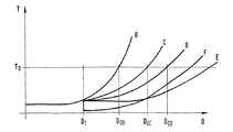
図4は同じように簡易化された、概略的な図を示す。この図は図3の特性曲線b〜eに相応する測定時間B〜Eを測定距離Dの関数として示す。明確に分かるように、選択によって、すなわち装置での測定不確かさの自由な設定または装置自体による設定によって、ある程度の測定時間T0内でさらに測定される距離領域D0が格段に拡張されている。装置に設定可能な測定不確かさは例えば、図3からわかるように、装置によって生じるものとして設定される測定不確かさを格段に上回ることができる。FIG. 4 shows a schematic diagram, similarly simplified. This figure shows the measurement times B to E corresponding to the characteristic curves b to e in FIG. As can be clearlyseen, by the selection, i.e. by setting by free setting or device itself measurementuncertainty of the apparatus, the distance region D0 is further determined at a certain within the measurement time T0 has been extended considerably. The measurementuncertainty that can be set in the device can be significantly greater than the measurementuncertainty set as caused by the device, for example, as can be seen from FIG.
従って本発明による方法並びに本発明による装置は、距離測定用測定装置によって使用可能な距離領域、すなわち距離測定装置による距離測定が可能な距離領域を容易な手段で拡張することができる。Therefore, the method according to the present invention and the device according to the present invention can expand the distance region that can be used by themeasuring device for distance measurement, that is, the distance region that can be measured by the distance measuring device, with easy means.
本発明による方法並びに、この方法を実行する本発明による距離測定装置は、この明細書中に示された実施例に制限されるものではない。The method according to the invention and thedistance measuring device according to the invention for carrying out this method are not restricted to the embodiments shown in this description.
殊に本発明の方法および、この方法を実行する本発明の距離測定装置は、位相測定原理の使用に制限されない。例えば伝播時間原理に従って作動する距離測定装置も同じように本発明の方法を使用することができる。In particular, the method according to the invention and thedistance measuring device according to the invention for carrying out this method are not restricted to the use of the phase measuring principle. For example, distance measuring devices operating according to the propagation time principle can use the method of the invention as well.
さらに本発明の方法は、光学式距離測定装置での使用に制限されない。本発明による方法は同じように例えば距離測定用超音波装置でも使用される。 Further, the method of the present invention is not limited to use with optical distance measuring devices. The method according to the invention is likewise used, for example, in a distance measuring ultrasonic device.
10 測定装置、 14 送出部、 16,17,26,36,44 測定ビーム、 18 受信部、 20 目標対象物、 22,24 送出器、 28,58 評価ユニット 10 measuring device, 14 sending unit, 16, 17, 26, 36, 44 measuring beam, 18 receiving unit, 20 target object, 22, 24 sending unit, 28, 58 evaluation unit
Claims (16)
Translated fromJapanese変調された測定ビーム(16,26,36)を目標対象物(20)の方向へ送出する少なくとも1つの送出器(22,24)を備えた少なくとも1つの送出部(14)と、
前記目標対象物(20)から戻って来る測定ビーム(17,44)を受信する少なくとも1つの受信部(18)と、
前記距離測定装置と前記目標対象物(20)との間の距離を求める制御および評価ユニット(28,58)を有している形式のものにおいて、
前記距離測定装置は、ユーザまたは当該距離測定装置によって設定された測定時間で行われた距離測定の信号ノイズ比の実際値(S/N−IST)と、ユーザまたは当該距離測定装置によって設定された距離測定精度から計算された信号ノイズ比の目標値(S/N−SOLL)とを比較する手段を有しており、
当該距離測定装置は、
前記実際値が目標値から偏差している場合に、
前記目標値を得るのに必要な、測定期間の数(n)を求め、当該測定期間の数(n)にわたって距離測定を行うか、
または
前記設定された距離測定精度の値を、前記設定された測定時間内での距離測定が可能になるまで徐々に低くする、手段を有している、
ことを特徴とする距離測定装置。A distance measuring device,
At least one delivery part (14) comprising at least one sender (22, 24) for delivering a modulated measurement beam (16, 26, 36) in the direction of the target object (20);
At least one receiver (18) for receiving a measurement beam (17, 44) returning from the target object (20);
In the type having a control and evaluation unit (28, 58) for determining the distancebetween thedistance measuring device and the target object (20) ,
The distance measuring device is set by the user or the distance measuring device andthe actual value (S / N-IST) of the signal-to-noiseratio of the distance measurement performed at the measuring time set by the user or the distance measuring device. A means for comparing the signal noise ratiotarget value (S / N-SOLL) calculated from the distance measurement accuracy;
The distance measuring device is
When the actual value deviates from the target value,
Required to obtain the targetvalue,we obtain thenumber (n)of the measurement period,or perform distance measurementover several (n)of themeasurement period,
Or the set value of the distance measurement accuracy, gradually lowered until it can distance measurement within the set measurement timehas hands stage,
A distance measuring device characterized by that.
当該記憶媒体内には前記距離測定の精度が、少なくとも1つの特性曲線の形で格納されている、請求項1記載の距離測定装置。Thedistance measuring device has a storage medium (64),
Thedistance measuring device according to claim 1, wherein the distance measurement accuracy is stored in the form of at least one characteristic curve in the storage medium.
当該特性曲線は距離測定装置の操作エレメント(62)を介して距離測定のために呼び出される、請求項2記載の距離測定装置。The storage medium has a plurality of characteristic curves (a, b, c, d, e, f) of the distance measurement accuracy that is a function of the measurement distance;
The characteristic curve is called for operating element (62) via a distance measurement of thedistance measuring device,a distance measuring apparatus according to claim 2, wherein.
当該特性曲線は距離測定装置の制御および評価ユニット(28,58)によって距離測定のために呼び出される、請求項2記載の距離測定装置。The storage medium (64) has a plurality of characteristic curves (a, b, c, d, e, f) of the distance measurement accuracy that is a function of the measurement distance;
The characteristic curve is called for distance measurement by the control and evaluation unit of thedistance measuring device (28, 58),the distance measuring apparatus according to claim 2, wherein.
当該測定パラメータグループの他の測定パラメータは距離測定装置の電子部分によって半自動的に調整され、測定信号の信号ノイズ比は測定過程時に設定値に達する、請求項5または6記載の距離測定装置。Saiddistance measuring device, the measurement parameter group including the distance measurement accuracy of the distance measurement time anddistance measuring device of thedistance measuring device so as to be selectively quantitatively pre by a user of the at least one measurement parameter isa distance measuring device Have means to
7. Thedistance measuring device according to claim 5, wherein the other measurement parameters of the measurement parameter group are adjusted semi-automatically by the electronic part of thedistance measuring device, and the signal-to-noise ratio of the measurement signal reaches a set value during the measurement process.
当該出力ユニットは、距離測定時に使用された測定精度および/または距離測定装置の距離分解能をあらわすことができる、請求項1から8までのいずれか1項記載の距離測定装置。It saiddistance measuring apparatushas aViewing unit (60),
Thedistance measuring device according to any one of claims 1 to 8, wherein the output unit can represent measurement accuracy and / or distance resolution of thedistance measuring device used duringdistance measurement .
当該出力ユニットは、距離測定の測定結果を測定精度に相応する距離測定値の小数位で表示することができる、請求項1から9までのいずれか1項記載の距離測定装置。It saiddistance measuring apparatushas aViewing unit (60),
Thedistance measuring device according to any one of claims 1 to 9, wherein the output unit is capable of displaying a distance measurement measurement result in a decimal place of a distance measurement value corresponding to the measurement accuracy.
距離測定装置(10)の少なくとも1つの送出部(14)が変調された測定ビーム(16,26,36)を目標対象物(20)の方向へ送出し、
前記目標対象物(20)から反射されて戻って来る測定ビーム(17,44)を前記距離測定装置(10)内で検出し、
前記反射された測定信号から、前記距離測定装置(10)と前記目標対象物(20)との間の距離を求める形式の方法において、
ユーザまたは当該距離測定装置によって設定された測定時間で行われた距離測定の信号ノイズ比の実際値(S/N−IST)と、ユーザまたは当該距離測定装置によって設定された距離測定精度から計算された信号ノイズ比の目標値(S/N−SOLL)とを比較し、
当前記実際値が目標値から偏差している場合に、
前記目標値を得るのに必要な、測定期間の数(n)を求め、当該測定期間の数(n)にわたって距離測定を行うか、
または
前記設定された距離測定精度の値を、前記設定された測定時間内での距離測定が可能になるまで徐々に低くする、
ことを特徴とする距離測定方法。A distance measuring method,
At least one delivery part (14) of thedistance measuring device (10) delivers the modulated measurement beam (16, 26, 36) in the direction of the target object (20);
A measuring beam (17, 44) reflected back from the target object (20) is detected in thedistance measuring device (10);
In a method of determining the distancebetween the distancemeasuring device (10) and the target object (20) from the reflected measurement signal,
The actual value of the signal to noise ratio of the distance measurements made by the measuring time set by the user or thedistance measuring device and(S / N-IST), is calculated from the distance measurement accuracy set by the user or the distance measuring device Compared withthe target value of the signal-to-noise ratio(S / N-SOLL)
When the actual value deviates from the target value,
Required to obtain the targetvalue, we obtain the number (n)of the measurement period,or perform distance measurementover several (n)of themeasurement period,
Or gradually decreasing the set distance measurement accuracy value until distance measurement is possible within the set measurement time,
A distance measuring method characterized by the above.
当該特性曲線は距離測定装置によって自動的におよび/または距離測定装置のユーザによって呼び出されるおよび/または選択される、請求項12または13記載の距離測定方法。The distance measurement accuracy value is stored in thedistance measuring device in the form of one or more characteristic curves;
14. The distance measuring method according to claim 12 or 13, wherein the characteristic curve is called and / or selected automatically by adistance measuring device and / or by a user of thedistance measuring device.
Applications Claiming Priority (2)
| Application Number | Priority Date | Filing Date | Title |
|---|---|---|---|
| DE10232878ADE10232878B4 (en) | 2002-07-19 | 2002-07-19 | Apparatus and method for distance measurement |
| DE10232878.1 | 2002-07-19 |
Related Parent Applications (1)
| Application Number | Title | Priority Date | Filing Date |
|---|---|---|---|
| JP2004528294ADivisionJP4709546B2 (en) | 2002-07-19 | 2003-05-12 | Distance measuring device and distance measuring method |
Publications (2)
| Publication Number | Publication Date |
|---|---|
| JP2010156711A JP2010156711A (en) | 2010-07-15 |
| JP4709931B2true JP4709931B2 (en) | 2011-06-29 |
Family
ID=30010234
Family Applications (2)
| Application Number | Title | Priority Date | Filing Date |
|---|---|---|---|
| JP2004528294AExpired - Fee RelatedJP4709546B2 (en) | 2002-07-19 | 2003-05-12 | Distance measuring device and distance measuring method |
| JP2010053949AExpired - Fee RelatedJP4709931B2 (en) | 2002-07-19 | 2010-03-11 | Distance measuring device and distance measuring method |
Family Applications Before (1)
| Application Number | Title | Priority Date | Filing Date |
|---|---|---|---|
| JP2004528294AExpired - Fee RelatedJP4709546B2 (en) | 2002-07-19 | 2003-05-12 | Distance measuring device and distance measuring method |
Country Status (6)
| Country | Link |
|---|---|
| US (1) | US7324218B2 (en) |
| EP (2) | EP1527321B1 (en) |
| JP (2) | JP4709546B2 (en) |
| KR (1) | KR101016565B1 (en) |
| DE (2) | DE10232878B4 (en) |
| WO (1) | WO2004017022A1 (en) |
Families Citing this family (22)
| Publication number | Priority date | Publication date | Assignee | Title |
|---|---|---|---|---|
| DE10232878B4 (en)* | 2002-07-19 | 2012-02-23 | Robert Bosch Gmbh | Apparatus and method for distance measurement |
| US7408627B2 (en)* | 2005-02-08 | 2008-08-05 | Canesta, Inc. | Methods and system to quantify depth data accuracy in three-dimensional sensors using single frame capture |
| DE102006013707A1 (en) | 2006-03-24 | 2007-09-27 | Robert Bosch Gmbh | Hand-held device e.g. laser rangefinder, for measuring distance, has electro-optical display reproducing measuring results, where distance measuring values are assigned to partial section of distance between object and end by ruler scale |
| DE102006013695A1 (en)* | 2006-03-24 | 2007-09-27 | Robert Bosch Gmbh | Electro-optical display unit for hand-held length measuring device e.g. roller-tape, has digital display comprising variable scale with scale point and numerical value, where orientation of scale is changed relative to display unit |
| CN101127202B (en)* | 2006-08-18 | 2011-07-27 | 鸿富锦精密工业(深圳)有限公司 | Display device parameter automatic regulation system and method |
| JP5466806B2 (en) | 2006-09-21 | 2014-04-09 | 株式会社トプコン | Optical distance measurement method, distance measurement program, and distance measurement apparatus |
| JP5466808B2 (en)* | 2006-09-29 | 2014-04-09 | 株式会社トプコン | Optical distance measurement method, distance measurement program, and distance measurement system |
| CN101271161B (en)* | 2007-03-22 | 2011-03-30 | 光宝科技股份有限公司 | Traffic Warning System Installed in Transportation Vehicles |
| TWI310354B (en)* | 2007-03-22 | 2009-06-01 | Lite On Technology Corp | Alarm system for a vehicle |
| US8107056B1 (en) | 2008-09-17 | 2012-01-31 | University Of Central Florida Research Foundation, Inc. | Hybrid optical distance sensor |
| US8213022B1 (en) | 2009-03-04 | 2012-07-03 | University Of Central Florida Research Foundation, Inc. | Spatially smart optical sensing and scanning |
| EP2378310B1 (en)* | 2010-04-15 | 2016-08-10 | Rockwell Automation Safety AG | Time of flight camera unit and optical surveillance system |
| DE102010062172A1 (en) | 2010-11-30 | 2012-05-31 | Hilti Aktiengesellschaft | Distance measuring device and surveying system |
| DE102010062161B4 (en) | 2010-11-30 | 2025-05-08 | Hilti Aktiengesellschaft | Handheld laser distance meter and surveying system |
| EP2602635B1 (en)* | 2011-12-06 | 2014-02-19 | ELMOS Semiconductor AG | Method for measuring a transfer route by means of compensating amplitude measurement and delta-sigma method and device for performing the method |
| US8879050B2 (en)* | 2012-12-04 | 2014-11-04 | Texas Instruments Incorporated | Method for dynamically adjusting the operating parameters of a TOF camera according to vehicle speed |
| CN105547282B (en)* | 2015-12-10 | 2019-04-02 | 科盾科技股份有限公司 | One kind being used for running fix mesh calibration method and measuring device |
| WO2017141957A1 (en)* | 2016-02-17 | 2017-08-24 | パナソニックIpマネジメント株式会社 | Distance measuring device |
| DE102016225411A1 (en) | 2016-12-19 | 2018-06-21 | Robert Bosch Gmbh | Laser rangefinders |
| US10394643B2 (en)* | 2017-08-16 | 2019-08-27 | National Instruments Corporation | Distributed run-time auto-calculation of measurement uncertainty |
| KR102138200B1 (en) | 2020-01-28 | 2020-07-27 | 주식회사 미성 | Feed bucket of fowls for breeding |
| DE102020128877B3 (en)* | 2020-11-03 | 2022-03-10 | Daimler Ag | Method for determining a change in a range of a lidar sensor |
Family Cites Families (29)
| Publication number | Priority date | Publication date | Assignee | Title |
|---|---|---|---|---|
| US3644740A (en)* | 1969-07-22 | 1972-02-22 | Hughes Aircraft Co | Control circuit for biasing a photodetector so as to maintain a selected false alarm rate |
| US4498764A (en)* | 1981-06-09 | 1985-02-12 | Ludwig Bolkow | Dynamic control arrangement for a distance measuring apparatus |
| JPS60113573U (en)* | 1984-01-05 | 1985-08-01 | 株式会社ニコン | light wave rangefinder |
| JPS6281519A (en)* | 1985-10-04 | 1987-04-15 | Mitsubishi Electric Corp | distance measuring device |
| US4895441A (en)* | 1987-03-19 | 1990-01-23 | Pandel Instruments, Inc. | Method and apparatus for precision ranging |
| JP2949888B2 (en)* | 1991-04-02 | 1999-09-20 | 富士電機株式会社 | Ultrasonic distance sensor |
| JP2500400Y2 (en)* | 1991-10-31 | 1996-06-05 | 松下電工株式会社 | Optical displacement measuring device |
| US5303020A (en)* | 1992-12-30 | 1994-04-12 | Litton Systems, Inc. | Optical transceiver apparatus having time programmed gain |
| JP3029357B2 (en)* | 1993-04-05 | 2000-04-04 | 三菱電機株式会社 | Dirt detection device for distance measuring device |
| JP3282331B2 (en)* | 1993-12-20 | 2002-05-13 | ミノルタ株式会社 | 3D shape measuring device |
| JP3465374B2 (en)* | 1994-09-16 | 2003-11-10 | 日産自動車株式会社 | Radar equipment for vehicles |
| DE4436447C2 (en)* | 1994-10-13 | 1996-10-02 | Leica Ag | Method and device for electro-optical distance measurement |
| US5828584A (en)* | 1994-12-19 | 1998-10-27 | Seiko Precision Inc. | Device for determining a distance range of an object |
| US5612779A (en) | 1995-01-19 | 1997-03-18 | Laser Technology, Inc. | Automatic noise threshold determining circuit and method for a laser range finder |
| AU690003B2 (en)* | 1995-01-19 | 1998-04-09 | Kama-Tech (Hk) Limited | Laser range finder |
| JPH09133764A (en)* | 1995-11-08 | 1997-05-20 | Nikon Corp | Distance measuring device |
| SE9600897D0 (en)* | 1996-03-07 | 1996-03-07 | Geotronics Ab | RANGE-FINDER |
| US5737085A (en)* | 1997-03-19 | 1998-04-07 | Systems & Processes Engineering Corporation | Precision optical displacement measurement system |
| US5946081A (en) | 1997-12-08 | 1999-08-31 | Asia Optical Co., Inc. | Method and apparatus for reducing the noise in the receiver of a laser range finder |
| DE19811550C2 (en)* | 1998-03-18 | 2002-06-27 | Bosch Gmbh Robert | Method and circuit arrangement for generating frequency signals |
| US6429941B1 (en)* | 1998-07-14 | 2002-08-06 | Minolta Co., Ltd. | Distance measuring equipment and method |
| DE19902455A1 (en)* | 1999-01-22 | 2000-08-10 | Bosch Gmbh Robert | Distance measuring method and device |
| JP2001051058A (en)* | 1999-08-11 | 2001-02-23 | Minolta Co Ltd | Apparatus for measuring distance |
| DE10020842A1 (en)* | 2000-04-28 | 2001-10-31 | Zeiss Carl | Coordinate measuring machine or machine tool |
| DE10066246A1 (en)* | 2000-09-22 | 2005-10-06 | Robert Bosch Gmbh | Scattered light smoke |
| JP3409117B2 (en)* | 2001-03-30 | 2003-05-26 | オムロン株式会社 | Optical reflective sensor |
| DE10124433A1 (en)* | 2001-05-18 | 2002-11-21 | Bosch Gmbh Robert | Device for optical distance measurement has components that allow easy variation of the beam path direction and divergence to match the target type and distance |
| DE10130763A1 (en)* | 2001-06-26 | 2003-01-02 | Bosch Gmbh Robert | Device for optical distance measurement over a large measuring range |
| DE10232878B4 (en)* | 2002-07-19 | 2012-02-23 | Robert Bosch Gmbh | Apparatus and method for distance measurement |
- 2002
- 2002-07-19DEDE10232878Apatent/DE10232878B4/ennot_activeExpired - Lifetime
- 2003
- 2003-05-12JPJP2004528294Apatent/JP4709546B2/ennot_activeExpired - Fee Related
- 2003-05-12EPEP03727233Apatent/EP1527321B1/ennot_activeExpired - Lifetime
- 2003-05-12WOPCT/DE2003/001522patent/WO2004017022A1/enactiveApplication Filing
- 2003-05-12DEDE50312666Tpatent/DE50312666D1/ennot_activeExpired - Lifetime
- 2003-05-12EPEP08102698.1Apatent/EP1927821B1/ennot_activeExpired - Lifetime
- 2003-05-12USUS10/503,650patent/US7324218B2/ennot_activeExpired - Lifetime
- 2003-05-12KRKR1020057000913Apatent/KR101016565B1/ennot_activeExpired - Fee Related
- 2010
- 2010-03-11JPJP2010053949Apatent/JP4709931B2/ennot_activeExpired - Fee Related
Also Published As
| Publication number | Publication date |
|---|---|
| JP2010156711A (en) | 2010-07-15 |
| JP4709546B2 (en) | 2011-06-22 |
| US7324218B2 (en) | 2008-01-29 |
| EP1927821A1 (en) | 2008-06-04 |
| DE50312666D1 (en) | 2010-06-10 |
| DE10232878A1 (en) | 2004-02-05 |
| KR101016565B1 (en) | 2011-02-22 |
| WO2004017022A1 (en) | 2004-02-26 |
| JP2005533264A (en) | 2005-11-04 |
| KR20050013184A (en) | 2005-02-02 |
| DE10232878B4 (en) | 2012-02-23 |
| EP1527321B1 (en) | 2010-04-28 |
| US20050083512A1 (en) | 2005-04-21 |
| EP1927821B1 (en) | 2015-10-21 |
| EP1527321A1 (en) | 2005-05-04 |
Similar Documents
| Publication | Publication Date | Title |
|---|---|---|
| JP4709931B2 (en) | Distance measuring device and distance measuring method | |
| JP3839851B2 (en) | Electronic distance measuring instrument | |
| US7336346B2 (en) | Distance measuring device and method thereof | |
| US7414707B2 (en) | Rangefinder and method for collecting calibration data | |
| US8786837B2 (en) | Distance measuring apparatus | |
| JP5502262B2 (en) | Method and apparatus for obtaining geodetic distance data | |
| EP1382979A1 (en) | Range finder, range finding method, and photoelectric tranducing circuit | |
| WO2010073994A1 (en) | Distance measurement device and distance measurement method | |
| US7728957B2 (en) | Device and method for optical distance measurement | |
| US7339655B2 (en) | Electric optical distance wavelength meter | |
| US20040145723A1 (en) | Electric distance meter | |
| US5737068A (en) | Electronic distance measuring device using a phase difference detection method | |
| JPH1123709A (en) | Distance measuring device | |
| CN106886027B (en) | Laser positioning device and laser positioning method | |
| KR20130012844A (en) | Method for automatic collecting of doppler angle and ultrasound system for the same | |
| US6803593B2 (en) | Distance measuring system | |
| JP2003130953A (en) | Distance measuring device | |
| EP1106963A2 (en) | Distance measuring device and method for adjusting photodetection unit | |
| CN109164455A (en) | A kind of phase distancemeter | |
| JP4002199B2 (en) | Light wave distance meter | |
| JP2005189140A (en) | Ranging device and method | |
| JPH11287859A (en) | Laser range finder | |
| JP2003130954A (en) | Distance measuring device | |
| CN108205126B (en) | Laser rangefinder | |
| JP2853350B2 (en) | Laser distance measuring device |
Legal Events
| Date | Code | Title | Description |
|---|---|---|---|
| A131 | Notification of reasons for refusal | Free format text:JAPANESE INTERMEDIATE CODE: A131 Effective date:20100721 | |
| A601 | Written request for extension of time | Free format text:JAPANESE INTERMEDIATE CODE: A601 Effective date:20101021 | |
| A602 | Written permission of extension of time | Free format text:JAPANESE INTERMEDIATE CODE: A602 Effective date:20101026 | |
| A601 | Written request for extension of time | Free format text:JAPANESE INTERMEDIATE CODE: A601 Effective date:20101122 | |
| A602 | Written permission of extension of time | Free format text:JAPANESE INTERMEDIATE CODE: A602 Effective date:20101130 | |
| A521 | Request for written amendment filed | Free format text:JAPANESE INTERMEDIATE CODE: A523 Effective date:20101216 | |
| RD03 | Notification of appointment of power of attorney | Free format text:JAPANESE INTERMEDIATE CODE: A7423 Effective date:20101216 | |
| RD04 | Notification of resignation of power of attorney | Free format text:JAPANESE INTERMEDIATE CODE: A7424 Effective date:20101227 | |
| TRDD | Decision of grant or rejection written | ||
| A01 | Written decision to grant a patent or to grant a registration (utility model) | Free format text:JAPANESE INTERMEDIATE CODE: A01 Effective date:20110218 | |
| A61 | First payment of annual fees (during grant procedure) | Free format text:JAPANESE INTERMEDIATE CODE: A61 Effective date:20110318 | |
| R150 | Certificate of patent or registration of utility model | Ref document number:4709931 Country of ref document:JP Free format text:JAPANESE INTERMEDIATE CODE: R150 | |
| R250 | Receipt of annual fees | Free format text:JAPANESE INTERMEDIATE CODE: R250 | |
| R250 | Receipt of annual fees | Free format text:JAPANESE INTERMEDIATE CODE: R250 | |
| R250 | Receipt of annual fees | Free format text:JAPANESE INTERMEDIATE CODE: R250 | |
| R250 | Receipt of annual fees | Free format text:JAPANESE INTERMEDIATE CODE: R250 | |
| R250 | Receipt of annual fees | Free format text:JAPANESE INTERMEDIATE CODE: R250 | |
| LAPS | Cancellation because of no payment of annual fees |