JP4709918B2 - Remote control device - Google Patents
Remote control deviceDownload PDFInfo
- Publication number
- JP4709918B2 JP4709918B2JP2009221051AJP2009221051AJP4709918B2JP 4709918 B2JP4709918 B2JP 4709918B2JP 2009221051 AJP2009221051 AJP 2009221051AJP 2009221051 AJP2009221051 AJP 2009221051AJP 4709918 B2JP4709918 B2JP 4709918B2
- Authority
- JP
- Japan
- Prior art keywords
- touch pad
- switch
- remote control
- signal
- control device
- Prior art date
- Legal status (The legal status is an assumption and is not a legal conclusion. Google has not performed a legal analysis and makes no representation as to the accuracy of the status listed.)
- Expired - Fee Related
Links
Images


Classifications
- H—ELECTRICITY
- H04—ELECTRIC COMMUNICATION TECHNIQUE
- H04N—PICTORIAL COMMUNICATION, e.g. TELEVISION
- H04N21/00—Selective content distribution, e.g. interactive television or video on demand [VOD]
- H04N21/40—Client devices specifically adapted for the reception of or interaction with content, e.g. set-top-box [STB]; Operations thereof
- H04N21/41—Structure of client; Structure of client peripherals
- H04N21/422—Input-only peripherals, i.e. input devices connected to specially adapted client devices, e.g. global positioning system [GPS]
- H04N21/42204—User interfaces specially adapted for controlling a client device through a remote control device; Remote control devices therefor
- H04N21/42206—User interfaces specially adapted for controlling a client device through a remote control device; Remote control devices therefor characterized by hardware details
- H04N21/42224—Touch pad or touch panel provided on the remote control
- H—ELECTRICITY
- H01—ELECTRIC ELEMENTS
- H01H—ELECTRIC SWITCHES; RELAYS; SELECTORS; EMERGENCY PROTECTIVE DEVICES
- H01H2217/00—Facilitation of operation; Human engineering
- H01H2217/032—Feedback about selected symbol, e.g. display
- H—ELECTRICITY
- H01—ELECTRIC ELEMENTS
- H01H—ELECTRIC SWITCHES; RELAYS; SELECTORS; EMERGENCY PROTECTIVE DEVICES
- H01H2225/00—Switch site location
- H01H2225/002—Switch site location superimposed
- H—ELECTRICITY
- H01—ELECTRIC ELEMENTS
- H01H—ELECTRIC SWITCHES; RELAYS; SELECTORS; EMERGENCY PROTECTIVE DEVICES
- H01H25/00—Switches with compound movement of handle or other operating part
- H01H25/04—Operating part movable angularly in more than one plane, e.g. joystick
- H01H25/041—Operating part movable angularly in more than one plane, e.g. joystick having a generally flat operating member depressible at different locations to operate different controls
- H—ELECTRICITY
- H01—ELECTRIC ELEMENTS
- H01H—ELECTRIC SWITCHES; RELAYS; SELECTORS; EMERGENCY PROTECTIVE DEVICES
- H01H9/00—Details of switching devices, not covered by groups H01H1/00 - H01H7/00
- H01H9/02—Bases, casings, or covers
- H01H9/0214—Hand-held casings
- H01H9/0235—Hand-held casings specially adapted for remote control, e.g. of audio or video apparatus
Landscapes
- Engineering & Computer Science (AREA)
- Human Computer Interaction (AREA)
- Multimedia (AREA)
- Signal Processing (AREA)
- Details Of Television Systems (AREA)
- Selective Calling Equipment (AREA)
- Position Input By Displaying (AREA)
Description
Translated fromJapanese本発明は、リモコン装置に関する。 The present invention relates to a remote control device.
従来のリモコン装置として、映像表示装置に表示された操作パネルをリモコン装置に備えられたタッチパッドに入力された操作内容に応じて操作するものが知られている(例えば、特許文献1)。 As a conventional remote control device, there is known a device that operates an operation panel displayed on a video display device in accordance with an operation content input to a touch pad provided in the remote control device (for example, Patent Document 1).
この特許文献1のリモコン装置は、利用者の指等の接触を操作位置として圧力で感知するタッチパッドと、映像表示装置に表示される操作パネルの操作位置とタッチパッドの操作位置とを対応付けてタッチパッドに摺動操作が行われたとき操作パネルの選択位置の移動を実行するとともに、タッチパッドに接触する指から加えられる圧力に応じて操作パネル上で決定を実行する操作制御部とを有するため、操作パネルに対する移動操作及び決定操作をタッチパッドで実行することができる。 The remote control device of
しかし、上記した従来のリモコン装置によると、タッチパッドで操作パネルに対する移動操作及び決定操作を行うことができるが、決定操作はタッチパッドに接触する指の圧力変化によって感知されるため、利用者は押下感を得ることができず、決定操作の実行成功又は失敗の判断が容易でないという問題がある。 However, according to the above-described conventional remote control device, a moving operation and a determining operation with respect to the operation panel can be performed with the touch pad. However, since the determining operation is detected by a change in pressure of a finger in contact with the touch pad, the user can There is a problem that a feeling of pressing cannot be obtained and determination of execution success or failure of the determination operation is not easy.
従って、本発明の目的は、摺動操作と押下感のある決定操作を利用者に提供することができるリモコン装置を提供することにある。 Therefore, an object of the present invention is to provide a remote control device that can provide a user with a sliding operation and a determination operation with a feeling of pressing.
[1]本発明は、上記した目的を達成するため、表面に第1の入力面を備える第1のタッチパッドと、前記第1のタッチパッドの前記第1の入力面と連続的に摺動操作が可能な第2の入力面を表面に備えた第2のタッチパッドと、前記第1のタッチパッドの押下動作に連動してスイッチング動作する第1のスイッチと、前記第2のタッチパッドの押下動作に連動してスイッチング動作する第2のスイッチとを有し、前記第1および第2のタッチパッドは、前記第1および第2の入力面への接触を静電容量の変化で感知し、前記第1および第2の入力面への接触位置を電気信号として出力するものであり、押下動作を受ける位置に応じて水平あるいは傾斜の姿勢をとって前記第1あるいは第2のスイッチを動作させることを特徴とするリモコン装置を提供する。[1] In order to achieve the above-described object, the present invention continuously slides on a first touch pad having a first input surface on the surface, and the first input surface of the first touch pad. A second touchpad having a second input surface that can be operated on the surface, a first switch that performs a switching operation in conjunction with a pressing operation of the firsttouchpad, and a second touchpad A second switch that performs a switching operation in conjunction with the pressing operation, and the first and second touchpadssense contact with the first and second input surfaces by a change in capacitance. The position of contact with the first and second input surfaces is output as an electrical signal, and the first or second switch is operated in a horizontal or inclined posture depending on the position to receivethe pressing operation. Remote control characterized by To provide a location.
上記した構成によれば、第1及び第2のタッチパッドを押下する操作と、それぞれのタッチパッド上の入力面における入力とを可能にしたため、第1及び第2のタッチパッドにおいてそれぞれ独立した押下感のある決定操作と、第1及び第2のタッチパッドにおいて両パッドが一体であっても、第1あるいは第2のスイッチを選択して動作させることができ、かつ、連続的な摺動操作を利用者に提供することができるリモコン装置を実現できる。According to the configuration described above, since the operation of pressing the first and second touch pads and the input on the input surface on each touch pad are enabled, the first and second touch pads can be pressed independently. Even ifboth the pads in the first and secondtouchpads are integrated with each other, the first or second switch can be selected and operated, and a continuous sliding operation Can be providedto the user.
本発明によれば、摺動操作と押下感のある決定操作を利用者に提供することができる。 According to the present invention, it is possible to provide a user with a sliding operation and a determination operation with a feeling of pressing.
〔第1の実施の形態〕
(映像表示装置の構成)
図1は、本発明の第1の実施の形態に係る映像表示装置の構成例を示す概略図である。[First Embodiment]
(Configuration of video display device)
FIG. 1 is a schematic diagram showing a configuration example of a video display apparatus according to the first embodiment of the present invention.
映像表示装置2は、アンテナ(図2、20A)を介して外部よりデジタル放送波等を受信して映像を表示したり、図示しないHDD(Hard Disc Drive)レコーダーやDVD(Digital Versatile Disc)プレイヤー等の外部映像再生装置から映像信号を受信して映像を表示するテレビ受像器等であって、前面に映像を表示するLCD(Liquid Crystal Display)パネル等から構成される表示部23Aと、音声を出力するスピーカ24A、24Bと、複数の操作スイッチを有するリモコン装置1から送信されるRF(Radio Frequency)信号を用いた操作信号を受信する受信部28とを有する。 The
また、映像表示装置2は、背面に図示しないアンテナ端子、外部入力端子及び複数のスイッチからなる操作部等を有し、本体2A内部には映像信号や音声信号を処理したり各部を制御するためのCPU(Central Processing Unit)、RAM(Random Access Memory)、ROM(Read Only Memory)及びHDD等からなる電子部品を有する。 The
リモコン装置1は、複数のスイッチ及びタッチパッドを有し、それらに対して操作入力されることで、映像表示装置2の各機能を操作する操作信号をRF信号を用いて送信する。 The
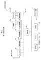
図2は、映像表示装置2の構成例を示すブロック図である。 FIG. 2 is a block diagram illustrating a configuration example of the
映像表示装置2は、チューナ20と、信号処理部21と、映像処理部22と、表示処理部23と、音声処理部24と、制御部25と、記憶部26と、RAM27と、受信部28とを有し、それぞれバス29で接続されている。 The
チューナ20は、デジタル放送局から送信される放送信号を受信するアンテナ20Aを備えており、受信した放送信号から所望のチャンネルの信号を選択して信号処理部21に送信する。 The
信号処理部21は、映像処理部22と音声処理部24とに接続されており、チューナ20から受信した放送信号を音声信号と映像信号に分離し、映像信号を映像処理部22に出力し、音声信号を音声処理部24に出力する。 The
映像処理部22は、表示処理部23を介して表示部23Aに接続されている。 The
表示処理部23は、入力された映像信号を画質調整し、画質調整した映像信号を表示部23Aに出力する。また、表示処理部23は、表示部23Aの表示調整を行う図示しないバックライト処理部及び色温度処理部等を有する。表示部23Aは、インバータ等により制御されて輝度を可変とするバックライトと、バックライトに照射されて映像を表示するLCDパネルとを有する。バックライト処理部は、バックライトの輝度値を変化させることで明るさを調整し、色温度処理部は、LCDパネルのγ設定値を変化させることで色温度を調整する。 The
音声処理部24はスピーカ24A及び24Bに接続されている。また、音声処理部24は、入力された音声信号の音質調整を行う。 The
また、映像表示装置2は、図示しない外部入力端子に接続された映像再生装置から送信される映像信号及び音声信号を受信する映像アナログ/デジタル変換器(A/D)及び音声A/Dを有し、映像A/D及び音声A/Dに入力された映像信号及び音声信号はアナログ信号からデジタル信号へと変換され、それらの出力信号はそれぞれ映像処理部22及び音声処理部24に出力される。 In addition, the
制御部25は、図2において矢印のない実線で示された制御線を介して各部を制御する。 The
記憶部26は、後述するリモコン装置1に入力された操作と映像表示装置2の各部を制御するための制御信号とを対応付ける操作テーブル260や、映像表示装置2によって録画された番組の映像情報等を格納する。 The
RAM27は、一時的に情報を格納して制御部25の動作を補助する。 The RAM 27 temporarily stores information and assists the operation of the
受信部28は、リモコン装置1が送信するRF信号を受信し、制御部25に出力する。 The
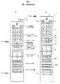
図3は、リモコン装置1の外観の構成例を示す概略図である。 FIG. 3 is a schematic diagram illustrating a configuration example of the external appearance of the
リモコン装置1は、上部筐体1A及び下部筐体1Bとから構成され、映像表示装置2の各機能を操作するための複数のスイッチを有しており、映像表示装置2の電源投入と遮断とを切り替える電源スイッチ10と、表示する映像情報のソースを切り替える入力切替スイッチ、ゲーム、地デジ、BS又はCSを選択するスイッチを備えた入力切替スイッチ群11と、チャンネルの選択や文字の入力等を行うチャンネル文字スイッチ群12、チャンネルの切り替えを行うチャンネル切替スイッチ13と、画面の表示形式を選択する画面表示スイッチ、ミュートスイッチ及びクイックスイッチ等を備えるスイッチ群14と、音量を調整する音量調整スイッチ15と、外部機器と映像表示装置2をリンクさせるリンクスイッチ、過去番組表を表示させるタイムスイッチ及び番組表を表示させる番組表スイッチ等を備えるスイッチ群16と、タッチパッドの機能と押下スイッチの機能とを備えたタッチパッドスイッチ17と、戻るスイッチ、ミニ番組表スイッチ、終了スイッチ、ブロードバンドスイッチ、dデータスイッチ、ニューススイッチ及びカラースイッチ等を備えたスイッチ群18とを有する。 The
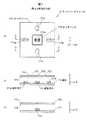
図4(a)〜(c)は、タッチパッドスイッチ17の構成例を示す概略図であり、図4(a)は平面図、図4(b)及び(c)はA−Aにおける断面図である。 4A to 4C are schematic diagrams illustrating a configuration example of the
タッチパッドスイッチ17は、表面17aが利用者の指等によって押下されることで−Z方向に沈み込むよう図示しない支持体によって支持されたタッチパッド17Aと、タッチパッド17Aの裏面17bが接触することによりその圧力を感知して感知信号を出力するスイッチとしての感圧素子170a及び171a〜171dとを有する。支持体としてはバネ等の反発力のあるものを用い、非操作時に裏面17bが各感圧素子170a及び171a〜171dに接触しないよう支持する。 In the
タッチパッド17Aは、利用者の指等による表面17aへの接触を、例えば、静電容量の変化で感知し、X方向及びY方向の操作位置を電気信号として出力する。タッチパッド17Aは、X方向に沿う複数のX方向電極と、Y方向に沿う複数のY方向電極と、複数のX方向電極と複数のY方向電極との間に設けられた絶縁体からなるスペーサとを備える。タッチパッド17Aの表面17aに指等で接触すると、接触したX方向電極とY方向電極との交差点の静電容量が変化し、この変化を後述する操作信号生成部100が電気信号に変換する。 The
タッチパッド17Aは、タッチパッド17Aの表面17aに対して感圧素子170a及び171a〜171dをそれぞれZ方向に投影した領域付近が押下されることで、感圧素子170a及び171a〜171dが圧力を感知するよう支持されている。例えば、タッチパッド17Aの表面17aの感圧素子171aに対応する領域付近が利用者の指等により押下されると、図4(c)に示すようにタッチパッド17Aの左半分が−Z方向に沈み込み、破線で示した状態となり、裏面17bが感圧素子171aと接触する。また、決定マーク170付近が押下されると、タッチパッド17A全体が−Z方向に沈み込み、図4(c)に示すように2点鎖線で示す状態となり、裏面17bが感圧素子170aと接触する。 In the
感圧素子170a、171a〜171dは、タッチパッド17Aを介して押下されたときの圧力に応じて抵抗値が減少し、その抵抗値を電気信号に変換して出力する。なお、感圧素子170a及び171a〜171dに換えて電子スイッチや機械スイッチを用いても良い。 The pressure-
また、タッチパッドスイッチ17は、タッチパッド17Aの表面17aに対して感圧素子170a及び171a〜171dをそれぞれZ方向に投影した領域付近に凹部を備え、利用者の指先に対して触覚の変化を与えることで、操作位置を提示する。 In addition, the
図5は、リモコン装置1の制御系の構成例を示すブロック図である。 FIG. 5 is a block diagram illustrating a configuration example of a control system of the
リモコン装置1は、電源スイッチ10、入力切替スイッチ群11、チャンネル文字スイッチ群12、チャンネル切替スイッチ13、スイッチ群14、音量調整スイッチ15、スイッチ群16、タッチパッドスイッチ17、スイッチ群18、後述するスイッチ群19A及び19Bの出力する信号を受信し、それぞれの信号に応じた操作信号を生成する操作信号生成部100と、操作信号生成部100が生成した操作信号をRF信号に変換して映像表示装置2に送信する操作信号送信部101とを有する。 The
また、操作信号生成部100は、図示しない電力供給線で上記した各スイッチに電力を供給するが、タッチパッド17Aに対して一定時間操作入力がないとき、タッチパッド17Aに対する電力供給を一時的に停止する。電力供給の再開は、映像表示装置2においてタッチパッド17Aを用いることができるメニュー画面等の表示がされたとき等に、映像表示装置2からリモコン装置1に対してRF信号によって解除信号を送信してもよい。また、映像表示装置2の各スイッチに対して所定の操作、例えば、タッチパッドスイッチ17の長押し等が実行されたときに、解除してもよい。 The operation
また、操作信号生成部100は、利用者の設定により、タッチパッド17Aが摺動操作の認識の可否を制御する。つまり、感圧素子170a及び171a〜171dの出力信号のみを受信し、タッチパッド17Aの出力信号を無視する。または、タッチパッド17Aに対する電力供給を遮断する。また、操作信号生成部100は、利用者の設定により、タッチパッド17Aに対する摺動操作の感度を制御する。例えば、摺動操作に対するタッチパッドの17Aの反応を遅い、標準、速い等から選択できるものとする。 Further, the operation
図6(a)及び(b)は、リモコン装置1の構成例を示す概略図である。 FIGS. 6A and 6B are schematic diagrams illustrating a configuration example of the
リモコン装置1は、上部筐体1Aを下部筐体1Bに対して図面の上下方向に移動可能に取り付けられており、図3に示す状態から上部筐体1Aを上方向に移動させると、図6(a)に示すように、スイッチ群19Aが露出する位置で上部筐体1Aが下部筐体1Bに対して止まるよう、例えば、上部筐体1Aと下部筐体1Bとの摺動面に互いに引っ掛かり合う爪と溝とを組にして設けることで構成される。 The
また、リモコン装置1は、図6(a)に示す状態から上部筐体1Aをさらに上方向に移動させると、図6(b)に示すように、スイッチ群19Aに加えてスイッチ群19Bが露出する位置で上部筐体1Aが下部筐体1Bに対して止まるよう構成される。このように、本実施の形態に係るリモコン装置1は、上部筐体1Aを下部筐体1Bに対して2段階にスライドさせる構成となっている。 When the
(映像表示装置の動作)
以下に、本発明の第1の実施の形態における映像表示装置の動作例を各図を参照しつつ説明する。(Operation of video display device)
Hereinafter, an operation example of the video display apparatus according to the first embodiment of the present invention will be described with reference to the drawings.
まず、利用者は、映像表示装置2の電源を投入するためにリモコン装置1の電源スイッチ10を押下する。リモコン装置1の操作信号生成部100は、電源スイッチ10が押下されると映像表示装置2の電源を投入するための操作信号を生成する。操作信号送信部101は、生成された操作信号を映像表示装置2にRF信号によって送信する。映像表示装置2の受信部28は、RF信号を受信すると制御部25に操作信号を出力し、制御部25は、受信した操作信号に基づいて図示しない電源部に映像表示装置2の電源を投入するよう要求する。 First, the user presses the
次に、利用者は、映像表示装置2の表示部23Aに表示される映像に応じてリモコン装置1の各スイッチを操作するが、以下では、タッチパッドスイッチ17を操作するときの動作について説明する。 Next, the user operates each switch of the
利用者がタッチパッドスイッチ17のタッチパッド17Aの表面17aを押下する操作をすると、感圧素子170a、171a〜171dのうち、利用者が押下した位置に対応する感圧素子が感知信号を操作信号生成部100に出力し、操作信号生成部100は、対応する感圧素子に応じた操作信号を生成する。次に、操作信号送信部101は、生成された操作信号を映像表示装置2にRF信号によって送信する。 When the user performs an operation of pressing down the
映像表示装置2の受信部28は、RF信号を受信すると制御部25に操作信号を出力し、制御部25は、受信した操作信号に基づいて操作テーブル260を参照し、操作テーブル260の定義に応じて映像表示装置2内の各部の動作を決定する。操作テーブル260は、例えば、表示部23Aに表示された映像等に応じて動作が変更されるよう定義してもよい。 When receiving the RF signal, the receiving
タッチパッド17Aの押下操作に対応する映像表示装置2の動作は、例えば、表示部23Aに表示される選択表示カーソル等の縦移動、横移動等の操作に対応したもの、及び決定やキャンセル操作に対応したものが挙げられる。 The operations of the
また、利用者がタッチパッドスイッチ17のタッチパッド17Aの表面17aに触れて、入力面上の接触位置を移動する摺動操作を行うと、タッチパッド17Aが感知信号を操作信号生成部100に出力し、操作信号生成部100は、接触位置の移動に応じた操作信号を生成する。次に、操作信号送信部101は、生成された操作信号を映像表示装置2にRF信号によって送信する。 When the user touches the
映像表示装置2の受信部28は、RF信号を受信すると制御部25に操作信号を出力し、制御部25は、受信した操作信号に基づいて操作テーブル260を参照し、操作テーブル260の定義に応じて映像表示装置2内の動作を決定する。 When receiving the RF signal, the receiving
タッチパッド17Aの入力面に対する摺動操作に対応する映像表示装置2の動作は、例えば、ウェブブラウザ表示時のポインタの自由移動、メニュー表示時のページ切替、ビデオ再生時の早送りや巻き戻し等の操作に対応したものが挙げられる。 The operation of the
(第1の実施の形態の効果)
上記した実施の形態によると、タッチパッドスイッチ17においてタッチパッド17Aを押下する操作と、タッチパッド17A上の入力面に対する入力を可能にした。このため、押下感のあるスイッチの決定操作を利用者に提供することができるとともに、タッチパッド17Aを用いた摺動操作を有するリモコン装置1を提供することができる。(Effects of the first embodiment)
According to the embodiment described above, the operation of pressing the
また、上部筐体1Aと下部筐体1Bとの相対的な移動により、スイッチ群19Aとスイッチ群19Bとを段階的に露出する構成としたため、使用頻度等によってスイッチ群19Aとスイッチ群19Bとを配置することで、用途に合わせてリモコン装置1の使用サイズを効率的に変化させることができる。 In addition, since the
また、タッチパッド17Aの表面17aに対して感圧素子170a及び171a〜171dをそれぞれZ方向に投影した領域付近に凹部を備えたため、利用者の指先に対して触覚の変化を与えることができ、利用者が押下操作をするときに容易に操作位置を確認することができる。なお、凹部に限らず、凸部や凹部及び凸部の組み合わせを用いても良い。 In addition, since the concave portions are provided in the vicinity of the areas where the pressure
〔第2の実施の形態〕
図7(a)〜(c)は、第2の実施の形態に係るタッチパッドスイッチ17の構成例を示す概略図であり、図7(a)は平面図、図7(b)及び(c)はそれぞれC−C及びD−Dにおける断面図である。[Second Embodiment]
FIGS. 7A to 7C are schematic views showing a configuration example of the
タッチパッドスイッチ17は、表面17aが利用者の指等によって押下されることで−Z方向に沈み込むよう図示しない支持体によって支持された2つのタッチパッド17B及び17Cと、タッチパッド17B及び17Cの裏面17bが接触することによりその圧力を感知して感知信号を出力するスイッチとしての感圧素子170a及び171a〜171dとを有する。 The
タッチパッド17B及び17Cは、それぞれ独立した決定ボタン及び十字操作キーの機能を有し、タッチパッド17B及び17Cの表面17aに対して感圧素子170a及び171a〜171dをそれぞれZ方向に投影した領域付近が押下されることで、感圧素子170a及び171a〜171dが圧力を感知するよう支持される。例えば、タッチパッド17Cの表面17aの感圧素子171aに対応する領域付近が指等により押下されると、図7(a)に示すタッチパッド17Aの左半分が−Z方向に沈み込み、裏面17bが感圧素子171aと接触する。また、タッチパッド17Bが押下されると、タッチパッド17B全体が−Z方向に沈み込み、裏面17bが感圧素子170aと接触する。 The
なお、決定ボタンとしてのタッチパッド17B及び十字キーとしての17Cそれぞれの表面17aは、利用者の指等の接触を、例えば、静電容量の変化で感知し、操作位置を出力する。また、タッチパッド17B及び17Cそれぞれの表面17aは、それぞれの境界において連続的に操作位置を出力するよう後述する操作信号生成部100を構成する。 Note that the
図8は、リモコン装置1の構成例を示すブロック図である。 FIG. 8 is a block diagram illustrating a configuration example of the
リモコン装置1は、タッチパッドスイッチ17としてタッチパッド17B及び17Cを含み、操作信号生成部100は、タッチパッド17B及び17Cの表面17aにおける摺動操作をそれぞれの境界において連続的に検知する。つまり、利用者の指が、例えば、タッチパッド17Cの表面17aの左端から右端にかけてタッチパッド17Bの表面17aを通過するとき、その操作位置の移動をタッチパッド17Cの表面17aの左端から右端にかけて一連のものとして扱う。 The
(第2の実施の形態の効果)
上記した実施の形態によると、第1の実施の形態の効果に加え、タッチパッド17Bとタッチパッド17Cとを分離し、感圧素子170aに対して比較的面積の小さいタッチパッド17Bを割り当てたため、決定ボタンとしてのタッチパッド17Bを押下する操作がより確実で容易となる。(Effect of the second embodiment)
According to the above-described embodiment, in addition to the effects of the first embodiment, the
また、決定ボタンにタッチパッド17Bを用いたため、決定操作をするボタンでありながら摺動操作が可能となる。さらに、タッチパッド17B及び17Cの境界を通過するような摺動操作を一連の操作として扱うため、タッチパッドスイッチ17の表面17aをすべて用いた摺動操作を実行することができる。 Further, since the
〔第3の実施の形態〕
図9(a)〜(c)は、第3の実施の形態に係るタッチパッドスイッチ17の構成例を示す概略図であり、図9(a)は、平面図、図9(b)及び(c)は、それぞれE−E及びF−Fにおける断面図である。[Third Embodiment]
FIGS. 9A to 9C are schematic views showing a configuration example of the
タッチパッドスイッチ17は、表面17aが利用者の指等によって押下されることで−Z方向に沈み込むよう図示しない支持体によって支持された4つのタッチパッド17D〜17Hと、押下されても沈み込まないよう固定されたタッチパッド17Iと、タッチパッド17D〜17Hの裏面17bが接触することによりその圧力を感知して感知信号を出力するスイッチとしての感圧素子170a及び171a〜171dとを有する。なお、タッチパッド17D〜17Iの表面17aは、利用者の指等の接触を、例えば、静電容量の変化で感知し、操作位置を出力する。 The
タッチパッド17D〜17Hは、表面17aが押下されることで、感圧素子170a及び171a〜171dが圧力を感知するよう支持される。例えば、タッチパッド17Dが押下されると、タッチパッド17D全体が−Z方向に沈み込み、裏面17bが感圧素子170aと接触する。 The
図10は、リモコン装置1の構成例を示すブロック図である。 FIG. 10 is a block diagram illustrating a configuration example of the
リモコン装置1は、タッチパッドスイッチ17としてタッチパッド17D〜17Iを含み、操作信号生成部100は、タッチパッド17D〜17Iの表面17aにおける摺動操作をそれぞれの境界において連続的に検知する。つまり、利用者の指が、例えば、タッチパッド17Iの表面17aの左端から右端にかけてタッチパッド17E、17D、17Fの表面17aを通過するとき、その操作位置の移動をタッチパッド17Iの表面17aの左端から右端にかけて一連のものとして扱う。 The
(第3の実施の形態の効果)
上記した実施の形態によると、第2の実施の形態の効果に加え、感圧素子170a及び171a〜171dに対して比較的面積の小さいタッチパッド17D及び17Eから17Hを割り当てたため、タッチパッド17D〜Hを押下する操作がより確実で容易となる。(Effect of the third embodiment)
According to the above-described embodiment, in addition to the effects of the second embodiment, the
[他の実施の形態]
なお、本発明は、上記実施の形態に限定されず、本発明の趣旨を逸脱しない範囲で種々な変形が可能である。例えば、タッチパッドスイッチ17のタッチパッドの分割数や分割の形状は限定しない。また、感圧素子の数や配置はタッチパッドの数や配置に合わせて適宜変更しても構わない。[Other embodiments]
The present invention is not limited to the above embodiment, and various modifications can be made without departing from the spirit of the present invention. For example, the number of touchpad divisions and the shape of division of the
また、タッチパッド17Aの裏面17bが感圧素子170a及び171a〜171dに部材等を介して間接的に接触する構成にしてもよい。また、感圧素子に換えて非接触スイッチ等を用いても良い。 Alternatively, the
1…リモコン装置、1A…上部筐体、1B…下部筐体、2…映像表示装置、2A…本体、10…電源スイッチ、11…入力切替スイッチ群、12…チャンネル文字スイッチ群、13…チャンネル切替スイッチ、14…スイッチ群、15…音量調整スイッチ、16…スイッチ群、17…タッチパッドスイッチ、17A−17I…タッチパッド、17a…表面、17b…裏面、18…スイッチ群、19A…スイッチ群、19B…スイッチ群、20…チューナ、20A…アンテナ、21…信号処理部、22…映像処理部、23…表示処理部、23A…表示部、24…音声処理部、24A…スピーカ、25…制御部、26…記憶部、27…RAM、28…受信部、29…バス、100…操作信号生成部、101…操作信号送信部、170…決定マーク、170a…感圧素子、171a−171d…感圧素子、260…操作テーブルDESCRIPTION OF
Claims (3)
Translated fromJapanese前記第1のタッチパッドの前記第1の入力面と連続的に摺動操作が可能な第2の入力面を表面に備えた第2のタッチパッドと、
前記第1のタッチパッドの押下動作に連動してスイッチング動作する第1のスイッチと、
前記第2のタッチパッドの押下動作に連動してスイッチング動作する第2のスイッチとを有し、
前記第1および第2のタッチパッドは、前記第1および第2の入力面への接触を静電容量の変化で感知し、前記第1および第2の入力面への接触位置を電気信号として出力するものであり、押下動作を受ける位置に応じて水平あるいは傾斜の姿勢をとって前記第1あるいは第2のスイッチを動作させることを特徴とするリモコン装置。A first touchpad having a first input surface on the surface;
A second touch pad provided on the surface with a second input surface capable of continuously sliding with the first input surface of the first touch pad;
A first switch that performs a switching operation in conjunction with a pressing operation of the first touch pad;
A second switch that performs a switching operation in conjunction with a pressing operation of the second touch pad ,
The first and second touch padssense contact with the first and second input surfaces by a change in capacitance, and a contact position with the first and second input surfaces is an electrical signal. A remote control device that outputs and operates the first or second switch in a horizontal or inclined posture depending on a position to receivea pressing operation.
Priority Applications (3)
| Application Number | Priority Date | Filing Date | Title |
|---|---|---|---|
| JP2009221051AJP4709918B2 (en) | 2009-09-25 | 2009-09-25 | Remote control device |
| US12/823,707US20110073382A1 (en) | 2009-09-25 | 2010-06-25 | Remote controller |
| US13/350,590US20120113040A1 (en) | 2009-09-25 | 2012-01-13 | Remote controller |
Applications Claiming Priority (1)
| Application Number | Priority Date | Filing Date | Title |
|---|---|---|---|
| JP2009221051AJP4709918B2 (en) | 2009-09-25 | 2009-09-25 | Remote control device |
Publications (2)
| Publication Number | Publication Date |
|---|---|
| JP2011071738A JP2011071738A (en) | 2011-04-07 |
| JP4709918B2true JP4709918B2 (en) | 2011-06-29 |
Family
ID=43779052
Family Applications (1)
| Application Number | Title | Priority Date | Filing Date |
|---|---|---|---|
| JP2009221051AExpired - Fee RelatedJP4709918B2 (en) | 2009-09-25 | 2009-09-25 | Remote control device |
Country Status (2)
| Country | Link |
|---|---|
| US (2) | US20110073382A1 (en) |
| JP (1) | JP4709918B2 (en) |
Families Citing this family (6)
| Publication number | Priority date | Publication date | Assignee | Title |
|---|---|---|---|---|
| WO2015027224A1 (en)* | 2013-08-23 | 2015-02-26 | Tiyqmat Research Llc | Remote control device |
| USD714740S1 (en)* | 2013-09-18 | 2014-10-07 | Savant Systems, Llc | Wi-fi remote control |
| JP2015125730A (en) | 2013-12-27 | 2015-07-06 | ソニー株式会社 | Coordinate input device |
| GB201408258D0 (en) | 2014-05-09 | 2014-06-25 | British Sky Broadcasting Ltd | Television display and remote control |
| KR20160139481A (en)* | 2015-05-27 | 2016-12-07 | 삼성전자주식회사 | User terminal apparatus and control method thereof |
| US20170242562A1 (en)* | 2016-02-19 | 2017-08-24 | Analogix Semiconductor, Inc. | Remote Controller |
Family Cites Families (11)
| Publication number | Priority date | Publication date | Assignee | Title |
|---|---|---|---|---|
| EP0477098B1 (en)* | 1990-09-18 | 1996-06-26 | Fujitsu Limited | Cursor displacement control device for a computer display |
| JP3514352B2 (en)* | 1996-07-16 | 2004-03-31 | 日本電信電話株式会社 | Tactile operation pad |
| JPH11339584A (en)* | 1998-05-29 | 1999-12-10 | Matsushita Electric Ind Co Ltd | Remote control device |
| JP2003271294A (en)* | 2002-03-15 | 2003-09-26 | Canon Inc | Data input device, data input method, and program |
| JP4109902B2 (en)* | 2002-05-27 | 2008-07-02 | キヤノン株式会社 | Display device |
| US20060100269A1 (en)* | 2003-01-29 | 2006-05-11 | Lambrou George N | Use of 10-aminoaliphatyl-dibenz[b,f]oxepines for the treatment of degenerative ocular disorders |
| US7499040B2 (en)* | 2003-08-18 | 2009-03-03 | Apple Inc. | Movable touch pad with added functionality |
| JP2006260028A (en)* | 2005-03-16 | 2006-09-28 | Sony Corp | Remote control system, remote controller, remote control method, information processor, information processing method and program |
| EP1758013B1 (en)* | 2005-08-24 | 2018-07-04 | LG Electronics Inc. | Mobile communications terminal having a touch input unit and controlling method thereof |
| JP2008140182A (en)* | 2006-12-01 | 2008-06-19 | Sharp Corp | Input device, transmission / reception system, input processing method, and control program |
| JP5710859B2 (en)* | 2007-09-21 | 2015-04-30 | ソニー株式会社 | Input device and electronic device |
- 2009
- 2009-09-25JPJP2009221051Apatent/JP4709918B2/ennot_activeExpired - Fee Related
- 2010
- 2010-06-25USUS12/823,707patent/US20110073382A1/ennot_activeAbandoned
- 2012
- 2012-01-13USUS13/350,590patent/US20120113040A1/ennot_activeAbandoned
Also Published As
| Publication number | Publication date |
|---|---|
| US20120113040A1 (en) | 2012-05-10 |
| US20110073382A1 (en) | 2011-03-31 |
| JP2011071738A (en) | 2011-04-07 |
Similar Documents
| Publication | Publication Date | Title |
|---|---|---|
| JP4709918B2 (en) | Remote control device | |
| US20220261090A1 (en) | System and method for multi-mode command input | |
| US8063884B2 (en) | Information processing apparatus, display control method, and program for controlling a display of the information processing apparatus based on an input received from a remote controller | |
| KR101521996B1 (en) | Input device having touch pad | |
| JP2008305174A (en) | Information processor, information processing method, and program | |
| KR100813981B1 (en) | User interface device and its implementation method | |
| CN102253796A (en) | Information processing system and apparatus | |
| US20110018802A1 (en) | Remote Control Device and Multimedia System | |
| JP2011082713A (en) | Small device | |
| CN104133582A (en) | Touch pad input apparatus having force sensor and input method using the same | |
| JP4814673B2 (en) | Digital broadcast receiver | |
| JP2008042520A (en) | Broadcast reception recording system and remote control device therefor | |
| JP2008092336A (en) | Information processing apparatus, transmitter, information processing system, and method thereof | |
| JP4738394B2 (en) | Electrical equipment | |
| JP7065367B2 (en) | Input device and audio output system | |
| CN100531331C (en) | Broadcast receiving apparatus | |
| JP2004334738A (en) | Input device | |
| JP5763579B2 (en) | Electronics | |
| JP4648846B2 (en) | Position input device and remote control device | |
| JP2010233157A (en) | Electronic apparatus with remote control device | |
| JPH11143634A (en) | Remote controller | |
| JP2013153292A (en) | Video audio apparatus | |
| JP2008227698A (en) | Television receiver | |
| JP4636871B2 (en) | In-vehicle electronic device and control method thereof | |
| JP4837143B1 (en) | Broadcast receiving system and electronic device |
Legal Events
| Date | Code | Title | Description |
|---|---|---|---|
| A61 | First payment of annual fees (during grant procedure) | Free format text:JAPANESE INTERMEDIATE CODE: A61 Effective date:20110318 | |
| LAPS | Cancellation because of no payment of annual fees |