JP4709159B2 - Plunger - Google Patents
PlungerDownload PDFInfo
- Publication number
- JP4709159B2 JP4709159B2JP2006540481AJP2006540481AJP4709159B2JP 4709159 B2JP4709159 B2JP 4709159B2JP 2006540481 AJP2006540481 AJP 2006540481AJP 2006540481 AJP2006540481 AJP 2006540481AJP 4709159 B2JP4709159 B2JP 4709159B2
- Authority
- JP
- Japan
- Prior art keywords
- plunger
- plane
- pair
- opening
- planes
- Prior art date
- Legal status (The legal status is an assumption and is not a legal conclusion. Google has not performed a legal analysis and makes no representation as to the accuracy of the status listed.)
- Expired - Fee Related
Links
Images


Classifications
- A—HUMAN NECESSITIES
- A61—MEDICAL OR VETERINARY SCIENCE; HYGIENE
- A61F—FILTERS IMPLANTABLE INTO BLOOD VESSELS; PROSTHESES; DEVICES PROVIDING PATENCY TO, OR PREVENTING COLLAPSING OF, TUBULAR STRUCTURES OF THE BODY, e.g. STENTS; ORTHOPAEDIC, NURSING OR CONTRACEPTIVE DEVICES; FOMENTATION; TREATMENT OR PROTECTION OF EYES OR EARS; BANDAGES, DRESSINGS OR ABSORBENT PADS; FIRST-AID KITS
- A61F6/00—Contraceptive devices; Pessaries; Applicators therefor
- A61F6/06—Contraceptive devices; Pessaries; Applicators therefor for use by females
- A61F6/14—Contraceptive devices; Pessaries; Applicators therefor for use by females intra-uterine type
- A61F6/18—Inserters or removers
Landscapes
- Health & Medical Sciences (AREA)
- Veterinary Medicine (AREA)
- Biomedical Technology (AREA)
- Reproductive Health (AREA)
- Vascular Medicine (AREA)
- Life Sciences & Earth Sciences (AREA)
- Animal Behavior & Ethology (AREA)
- General Health & Medical Sciences (AREA)
- Engineering & Computer Science (AREA)
- Public Health (AREA)
- Heart & Thoracic Surgery (AREA)
- Infusion, Injection, And Reservoir Apparatuses (AREA)
- Orthopedics, Nursing, And Contraception (AREA)
- Reciprocating Pumps (AREA)
- Pistons, Piston Rings, And Cylinders (AREA)
- Medicinal Preparation (AREA)
- Medicines That Contain Protein Lipid Enzymes And Other Medicines (AREA)
- Feeding Of Workpieces (AREA)
- Vending Machines For Individual Products (AREA)
- Surgical Instruments (AREA)
Description
Translated fromJapanese本発明はインサータ(inserter)のプランジャの先端(tip)の装置に関する。特に、本発明はT字体を有する子宮内装置用インサータのためのプランジャに関し、このプランジャは第一端および第二端、ならびにプランジャの長手方向である第一寸法を有し、プランジャの長手が長手方向に垂直の断面の直径よりも実質的に大きく、かつプランジャの断面が実質的円形であり、かつプランジャを貫通する開口部が、開口部の長軸がプランジャの長軸と実質的同一になるように、長手方向に配置されている。 The present invention relates to a device for a plunger tip of an inserter. In particular, the present invention relates to a plunger for an inserter for an intrauterine device having a T-shape, the plunger having a first end and a second end and a first dimension that is the longitudinal direction of the plunger, wherein the length of the plunger is longitudinal. Substantially larger than the diameter of the cross section perpendicular to the direction, the plunger cross section is substantially circular, and the opening through the plunger has the major axis of the opening substantially identical to the major axis of the plunger In this way, they are arranged in the longitudinal direction.
既知インサータ、例えば子宮内装置を位置決めするために使用されるインサータにおいて、子宮内装置は、通常、かかる装置をインサータの先端およびプランジャを介して所定場所へ引っ張ることによりインサータのプランジャ内に設置されるように構成される。そのために、先端は、子宮内装置に損傷を与えることなく装置をインサータ内に引っ張ることのできるように設計されなければならない。 In known inserters, for example, inserters used to position an intrauterine device, the intrauterine device is typically installed within the plunger of the inserter by pulling such device through the inserter tip and plunger into place. Configured as follows. To that end, the tip must be designed so that the device can be pulled into the inserter without damaging the intrauterine device.
代表的子宮内装置は、一つの本体部と二つの枝部を有する、所謂T字体を有し、金属スパイラルまたはホルモンカプセルがT字体内に設置される。本体部の端はループを有しストリングがそこに取り付けられていて、ストリングにより装置をプランジャへ引っ張り、かつ使用後に子宮から除去する。子宮内装置は代表的には前方でこのループによりプランジャへ引っ張られる。従って、プランジャが装置をプランジャの正確な位置、即ちループ(そしてT字体の残部)を損傷することなく、誘導することが重要である。 A typical intrauterine device has a so-called T-shape with one body and two branches, and a metal spiral or hormone capsule is placed in the T-shape. The end of the body has a loop with a string attached to it, which pulls the device to the plunger and removes it from the uterus after use. The intrauterine device is typically pulled forward by this loop to the plunger. It is therefore important that the plunger guides the device without damaging the exact position of the plunger, i.e. the loop (and the rest of the T-shape).
子宮内装置が間違った位置へ引き込まれる場合には、インサータまたはプランジャの先端縁はループの縁を損傷する。かかる引っ張りが続きかつ子宮内装置が正確な位置へ運ばれない場合には、最終的にストリングがT字体のループを切断することになる。損傷したループの縁は、更にループそして装置をインサータまたはプランジャ内へ押し込む原因になる。 If the intrauterine device is retracted to the wrong position, the tip edge of the inserter or plunger will damage the loop edge. If such pulling continues and the intrauterine device is not brought to the correct location, the string will eventually break the T-shaped loop. Damaged loop edges cause further loops and devices to be pushed into the inserter or plunger.
例えば、子宮内装置の位置決めに意図された従来技術によるインサータにおいて、プランジャの先端部は、装置のT字体を約30°の角度から、そして50%のケースにおいて60°の角度から正確位置へ回転させるように形成される。この種の構造は添付図面の図1、そして特許FI97946に示されている。 For example, in a prior art inserter intended for positioning an intrauterine device, the tip of the plunger rotates the T-shape of the device from an angle of approximately 30 ° and in a 50% case from an angle of 60 ° to the correct position. To be formed. This type of structure is shown in FIG. 1 of the accompanying drawings and in patent FI97946.
本発明の課題は、上述の問題を解決するインサータのプランジャを提供することにある。特に、本発明の課題は、装置に対する損傷の危険性を最小限にできるようにプランジャ内への装置の位置決めを可能にする先端構造を有するインサータのプランジャを提供することである。 The subject of this invention is providing the plunger of the inserter which solves the above-mentioned problem. In particular, it is an object of the present invention to provide an inserter plunger having a tip structure that allows positioning of the device within the plunger so that the risk of damage to the device can be minimized.
本発明の課題は添付の特許請求の範囲に記載された発明により達成される。 The object of the present invention is achieved by the invention described in the appended claims.
本発明の課題は、T字体を有する子宮内装置用インサータのためのプランジャであり、このプランジャは、第一端および第二端、ならびにプランジャの長手方向の第一寸法を有し、プランジャの長さは長手方向に垂直の断面の直径よりも実質的に大きく、かつプランジャの断面は実質的円形であり、かつプランジャを貫通する開口部が、開口部の長軸がプランジャの長軸と実質的同一となるように、長手方向に配置されている。 The subject of the present invention is a plunger for an inserter for an intrauterine device having a T-shape, the plunger having a first end and a second end and a first dimension in the longitudinal direction of the plunger, the length of the plunger Is substantially larger than the diameter of the cross section perpendicular to the longitudinal direction, and the cross section of the plunger is substantially circular, and the opening through the plunger has a major axis substantially equal to the major axis of the plunger. It arrange | positions in the longitudinal direction so that it may become the same.
本発明によるインサータの本体は、プランジャの第一端の開口部が先端部を形成する長軸の方向に対して垂直方向に拡大するように配置され、それにより先端部が、先端部の長手の少なくとも一部に沿って、長軸と平行の第一平面に対して少なくとも35°回転しかつ長軸に対して所定角度の平面に対して少なくとも35°回転した少なくとも一つの面を有することを特徴とする。 The main body of the inserter according to the present invention is arranged such that the opening at the first end of the plunger expands in a direction perpendicular to the direction of the long axis forming the tip, so that the tip is longer than the length of the tip. At least one surface having at least one surface rotated at least 35 ° with respect to a first plane parallel to the major axis and at least 35 ° with respect to a plane at a predetermined angle with respect to the major axis. And
本発明によるインサータのプランジャは、子宮内装置のインサータへの設置を促進する装置を先端部に有し、それにより子宮内装置への損傷を従来インサータよりも実質的に減少する。例えば、T字体を有する子宮内装置がプランジャへ設置される場合にプランジャの先端はT字体を実質的に大きい誤った角度から正確な位置へ回転させる。 The plunger of the inserter according to the present invention has a device at the tip that facilitates the placement of the intrauterine device into the inserter, thereby substantially reducing damage to the intrauterine device over conventional inserters. For example, when an intrauterine device having a T-shape is installed on the plunger, the tip of the plunger rotates the T-shape from a substantially large wrong angle to the correct position.
プランジャの先端構造がT字体を90°の角度からでも正確な位置へ回転させることが模型の使用により知見されている。 It has been found through the use of the model that the tip structure of the plunger rotates the T-shaped body to the correct position even from an angle of 90 °.
先端部の少なくとも一つの面は、例えば90°の角度のような急激な不連続を伴わない一表面を意味する。 At least one surface of the tip means a surface without a sharp discontinuity, for example an angle of 90 °.
本発明の実施形態によれば、長軸に対して所定角度を形成する前記平面は長軸の方向に対して垂直である。本発明の他の実施形態によれば、少なくとも一つの面は第一平面に対して90°回転しかつ所定角度の平面に対して90°回転している。 According to an embodiment of the present invention, the plane forming a predetermined angle with respect to the major axis is perpendicular to the direction of the major axis. According to another embodiment of the invention, the at least one surface is rotated 90 ° relative to the first plane and 90 ° relative to the plane at a predetermined angle.
本発明によるプランジャの先端部は一つまたはそれ以上の面を有する。例えば、二、三、四、五、六、七、八、九、十または十二面であってよい。 The tip of the plunger according to the invention has one or more faces. For example, it may be two, three, four, five, six, seven, eight, nine, ten, or twelve.
本発明によるプランジャにおいて、先端部の面は複数対の面を形成してよい。 In the plunger according to the present invention, the surface of the tip may form a plurality of pairs of surfaces.
本発明の一実施形態によれば、二つの面が一対の面を形成し、そのようにして対の面を形成する二つの面が長軸に平行の第二平面に対して相互に対称的であり、第二平面は第一平面に対して垂直である。 According to one embodiment of the present invention, the two surfaces form a pair of surfaces, and thus the two surfaces forming the pair of surfaces are symmetrical with respect to a second plane parallel to the major axis. And the second plane is perpendicular to the first plane.
本発明の他の実施形態によれば、先端部は四つの面を有し、四つの面は二対の面を形成し、二対の面は長軸に平行の第一平面に対して相互に対称的である。更に、少なくとも一対の面、例えば第二対面において、対を形成する二つの面は長軸に平行の第二平面に対して相互に対称的であり、第二平面は第一平面に対して垂直である。二対の面において、対を形成する面は平面に対して相互に対称的であることが有利である。 According to another embodiment of the present invention, the tip has four faces, the four faces form two pairs of faces, the two pairs of faces being mutually relative to a first plane parallel to the major axis. Is symmetrical. Furthermore, in at least one pair of surfaces, for example, the second facing surface, the two surfaces forming the pair are symmetrical to each other with respect to the second plane parallel to the major axis, and the second plane is perpendicular to the first plane. It is. In two pairs of planes, the planes forming the pairs are advantageously symmetric with respect to the plane.
実施形態において、対の面は相互に連結されていてよい。換言すれば、先端構造は必ずしも直角または不連続点を含む必要はない。対の面は、図面を参照して後述するように、相互に連結されなくてもよい。 In an embodiment, the pair of surfaces may be connected to each other. In other words, the tip structure need not necessarily include right angles or discontinuities. The pair of faces need not be connected to each other, as will be described later with reference to the drawings.
しかし、図示された一実施形態によれば、先端構造は直角を含んでよい。 However, according to one illustrated embodiment, the tip structure may include a right angle.
本発明によるプランジャは、第一平面と実質的平行である少なくとも一つの面を更に含んでよい。 The plunger according to the present invention may further comprise at least one surface that is substantially parallel to the first plane.
本発明の一実施形態によれば、一つの面または複数面のうちの一面は二つの平面に対して実質的90°回転する。当然ながら、二つまたは三つの面が二つの平面に対して実質的90°回転していてよく、それにより他の面が、例えば45°、60°、70°または82°等の他の角度に対応して回転していてよい。一対の面を形成する二つの面が45°または概ね実質的90°未満回転している場合には、一種の鋭角が対の面の結合部分に生じる。 According to one embodiment of the present invention, one surface or one of the surfaces rotates substantially 90 ° relative to the two planes. Of course, two or three planes may be rotated substantially 90 ° relative to the two planes so that the other plane can have other angles such as 45 °, 60 °, 70 ° or 82 °, for example. It may be rotated corresponding to. If the two faces forming the pair of faces are rotated by less than 45 ° or substantially substantially less than 90 °, a kind of acute angle occurs at the joining portion of the pair of faces.
本発明の実施形態によれば、一つの面または複数面のうちの一面は、二つの平面の少なくとも一つの平面に対して実質的90°回転している。一実施形態によれば、それらの面は全て二つの平面に対して実質的90°回転していてよい。ただし、当業者に理解されるように、かかる面は、例えば、50°、60°、65°、70°、75°、82°、87°、89、91°または92°等回転していてよい。 According to an embodiment of the present invention, one surface or one of the surfaces is rotated substantially 90 ° with respect to at least one of the two surfaces. According to one embodiment, all of these planes may be rotated substantially 90 ° relative to the two planes. However, as will be appreciated by those skilled in the art, such planes are rotated, for example, 50 °, 60 °, 65 °, 70 °, 75 °, 82 °, 87 °, 89, 91 ° or 92 °. Good.
一つまたはそれ以上の面は、プランジャの断面の平面方向に実質的平行の先端の全長に沿っていてよい。プランジャの断面の平面はプランジャの長軸に垂直の平面である。前記複数の面または一つの面は、先端部の長手に沿って、プランジャの断面の平面の方向とは異なる方向を有していてよい。換言すれば、面はプランジャの断面の平面に対して傾斜していてよい。自明なように、色々な組み合わせが可能であり、異なる面が先端部の長手に沿って異なる方向を有していてよい。 One or more surfaces may be along the entire length of the tip substantially parallel to the planar direction of the cross section of the plunger. The plane of the cross section of the plunger is a plane perpendicular to the long axis of the plunger. The plurality of surfaces or one surface may have a direction different from the direction of the plane of the cross section of the plunger along the length of the tip portion. In other words, the surface may be inclined with respect to the plane of the cross section of the plunger. As is obvious, various combinations are possible, and different surfaces may have different directions along the length of the tip.
次に、本発明を、非制限的な図面を参照して更に詳細に説明する。 The invention will now be described in more detail with reference to the non-limiting drawings.
図1は、子宮内装置の位置決めに使用される従来技術によるインサータのプランジャの先端構造(tip structure)を示す。 FIG. 1 shows the tip structure of a prior art inserter plunger used to position an intrauterine device.
図2は本発明の第一実施形態によるプランジャの先端構造を示す。
この図は四つの面のうち三つ、即ち面1、2および3を示し、面1および2は一対の面を形成し、面3は第四面と対を形成する。この形態において、一対の面は相互に対して連結されている。FIG. 2 shows the tip structure of the plunger according to the first embodiment of the present invention.
This figure shows three of the four faces, namely faces 1, 2 and 3, where faces 1 and 2 form a pair of faces and face 3 forms a pair with the fourth face. In this form, the pair of surfaces are connected to each other.
図3は本発明の第二形態によるプランジャの先端構造の長手断面を示す。この断面は長軸4に沿って切断されている。この図は一対の面が長軸4に平行の第一平面に対して相互に対称的であることを示す。この事例において、第一面は紙の表面に垂直である。この図は更に先端部の長さhを示す。 FIG. 3 shows a longitudinal section of a tip structure of a plunger according to the second embodiment of the present invention. This cross section is cut along the
図4および5は本発明の第三形態によるプランジャの先端構造を示す。図は四つの面6、7、8および9を示し、二つの面6および7は第一対面を形成し、かつ二つの面8および9は第二対面を形成する。図示形態において、全四つの面は二つの平面に対して実質的90°回転している。この形態において、四つの面は相互に対して連結されていないが、面10および11は対面間に存在し、面10および11は、プランジャの断面の平面方向に実質的平行である。 4 and 5 show the tip structure of the plunger according to the third embodiment of the present invention. The figure shows four surfaces 6, 7, 8 and 9, the two surfaces 6 and 7 forming a first pair and the two surfaces 8 and 9 forming a second surface. In the illustrated form, all four surfaces are rotated substantially 90 ° relative to the two planes. In this configuration, the four surfaces are not connected to each other, but the
図4は長軸と平行の第一面5を更に示し、一対の面は第一平面5に対して相互に対称的である。図5は図4と同様の形態のプランジャの先端を示すが、図5は第一平面5に垂直の平面12を示す。 FIG. 4 further shows a first surface 5 parallel to the major axis, the pair of surfaces being symmetrical with respect to the first plane 5. FIG. 5 shows the tip of a plunger having the same configuration as FIG. 4, but FIG. 5 shows a
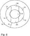
図6は本発明の第四形態によるプランジャの先端構造を、プランジャの第一端から見た状態で示す。この図は面13、14、15および16、ならびにプランジャの開口部17を示す。この図は開口部の長軸がプランジャの長軸と同一であることを示す。この図は、更に、面13および14により形成される対の面が面15および16により形成される対の面と対称的でないことを示すが、面13および14が、他方の面15および16よりも、上部の長手に沿った、回転が少ないことを示す。この形態において、先端は外シエル18を更に有し、外シエルは先端部の全長に沿って実質的均一の壁厚Pを有する。図2に示された形態はこれと同様の外シエルを有する。FIG. 6 shows the plunger tip structure according to the fourth embodiment of the present invention as seen from the first end of the plunger. This figure faces 13, 14, 15 and 16, as well as the
図示第四形態は、更に、第三形態の面(10および11)に対応する面19および20を有し、かつこれらの面19および20はプランジャの断面の平面方向に実質的平行である。 The fourth form shown further has faces 19 and 20 corresponding to the faces (10 and 11) of the third form, and these
図7は本発明の第五形態によるプランジャの先端構造を示す。
この形態において、先端構造は面21を有し、この面21はプランジャの断面の方向に実質的平行、即ちプランジャ端面の方向に実質的平行である。更に、先端構造はこの面21に隣接して面22を有し、面22は下縁で面21に対して垂直であり、そこからかつプランジャ端面の方向へ向かって回転して端面に近接している。これは、第二平面に対して対称的な一対の面を形成する。先端構造の他側は、弓状の面23により形成されている。この形態において、先端構造の他側は正確位置へ向いかつ回転し、他側は誤った位置の創出を阻止し、かつインサータが先端構造内に残留するのを阻止する。FIG. 7 shows a tip structure of a plunger according to the fifth embodiment of the present invention.
In this configuration, the tip structure has a
Claims (10)
Translated fromJapanese第一端および第二端、ならびに
プランジャの長手方向の第一寸法を有し、
プランジャの長さが長手方向に垂直の断面の直径よりも実質的に大きく、
プランジャの断面が実質的円形であり、かつ
プランジャを貫通する開口部が、開口部の長軸がプランジャの長軸と実質的同一になるように、長手方向に配置されたプランジャにおいて、
プランジャの第一端において開口部は、
前記長軸に対して垂直方向外方に拡大するように配置され、前記長軸の方向に垂直の平面に対して略35°回転した先端面が開口部外周に沿って形成され、
前記先端面から長軸方向内方へ所定間隔おいて、前記長軸に対して垂直方向に前記開口部を挟んで対面する一対の平面を含み、かつ
前記一対の平面に対して50°から92°の範囲で回転して前記プランジャの長軸と平行の第一平面に対して相互に対称的な面を形成する四つの長軸方向の面を含み、
前記四つの長軸方向の面は、前記先端面側で、前記先端面の方向に向かって回転し前記先端面に接近して二対の上面を形成し、各対の上面は相互に対して連結されていることを特徴とする、プランジャ。A plunger for an inserter for an intrauterine device having a T-shape,
Having a first end and a second end, and a first dimension in the longitudinal direction of the plunger;
The length of the plunger is substantially larger than the diameter of the cross section perpendicular to the longitudinal direction;
In a plunger arranged in a longitudinal direction,wherein the plunger has a substantially circular cross section and the opening through the plunger is such that the long axis of the opening is substantially identical to the long axis ofthe plunger,
Openingin the first end of theplunger,
Is arranged to expandin the vertical directionoutwardly againstthe long axis,the distal end surface that is rotatedapproximately 35 ° relative to a plane perpendicular to the direction ofthe long axisis formed along the opening periphery,
A pair of planes facing each other across the opening in a direction perpendicular to the major axis at a predetermined interval from the tip surface inward in the major axis direction; and
Including four longitudinal planes that rotate within a range of 50 ° to 92 ° with respect to the pair of planes to form mutually symmetrical planes with respect to a first plane parallel to the major axis of the plunger. ,
The four long-axis-direction surfaces rotate toward the distal end surface on the distal end surface side, approach the distal end surface, and form two pairs of upper surfaces. A plunger characterizedby being connected .
Applications Claiming Priority (3)
| Application Number | Priority Date | Filing Date | Title |
|---|---|---|---|
| FI20031679AFI119719B (en) | 2003-11-19 | 2003-11-19 | A slider |
| FI20031679 | 2003-11-19 | ||
| PCT/FI2004/000688WO2005048893A1 (en) | 2003-11-19 | 2004-11-17 | Plunger |
Publications (3)
| Publication Number | Publication Date |
|---|---|
| JP2007511310A JP2007511310A (en) | 2007-05-10 |
| JP2007511310A5 JP2007511310A5 (en) | 2007-11-15 |
| JP4709159B2true JP4709159B2 (en) | 2011-06-22 |
Family
ID=29558648
Family Applications (1)
| Application Number | Title | Priority Date | Filing Date |
|---|---|---|---|
| JP2006540481AExpired - Fee RelatedJP4709159B2 (en) | 2003-11-19 | 2004-11-17 | Plunger |
Country Status (12)
| Country | Link |
|---|---|
| US (1) | US7661429B2 (en) |
| EP (1) | EP1691740B1 (en) |
| JP (1) | JP4709159B2 (en) |
| AT (1) | ATE400239T1 (en) |
| DE (2) | DE602004014972D1 (en) |
| DK (1) | DK1691740T3 (en) |
| ES (1) | ES2309581T3 (en) |
| FI (1) | FI119719B (en) |
| HR (1) | HRP20080500T3 (en) |
| PL (1) | PL1691740T3 (en) |
| PT (1) | PT1691740E (en) |
| WO (1) | WO2005048893A1 (en) |
Families Citing this family (14)
| Publication number | Priority date | Publication date | Assignee | Title |
|---|---|---|---|---|
| US11992431B2 (en) | 2008-09-17 | 2024-05-28 | Bayer Oy | Inserter |
| FI20080523A0 (en) | 2008-09-17 | 2008-09-17 | Bayer Schering Pharma Oy | An inserter |
| ES2424984T5 (en) | 2008-09-17 | 2017-02-16 | Bayer Oy | Inserter |
| FI20080524A0 (en) | 2008-09-17 | 2008-09-17 | Bayer Schering Pharma Oy | An inserter |
| FI122579B (en) | 2010-10-29 | 2012-03-30 | Bayer Oy | inserter |
| US10028858B2 (en) | 2011-07-11 | 2018-07-24 | Medicines360 | Intrauterine systems, IUD insertion devices, and related methods and kits therefor |
| USD718435S1 (en) | 2012-05-30 | 2014-11-25 | Medicines360 | Intrauterine insertion device |
| US9265652B2 (en) | 2012-08-14 | 2016-02-23 | Contramed, Llc | Intrauterine contraceptive device |
| US9089418B2 (en) | 2012-08-14 | 2015-07-28 | Contramed, Llc | Intrauterine contraceptive device |
| US10188546B2 (en) | 2013-10-14 | 2019-01-29 | Sebela Vlc Limited | Intrauterine device with controlled copper ion elution |
| US10918516B2 (en) | 2013-10-14 | 2021-02-16 | Sebela Vlc Limited | Intrauterine device with controlled copper ion elution |
| US9180040B2 (en) | 2013-10-18 | 2015-11-10 | Contramed, Llc | Intrauterine device with retrieval thread |
| CA3160029A1 (en) | 2019-10-09 | 2021-04-15 | Steven R. Bacich | Apparatus and method for everting catheter for iud delivery and placement in the uterine cavity |
| US11571329B2 (en) | 2019-11-21 | 2023-02-07 | Coopersurgical, Inc. | Packaging systems for implantable devices and related methods |
Family Cites Families (14)
| Publication number | Priority date | Publication date | Assignee | Title |
|---|---|---|---|---|
| US2338135A (en)* | 1942-03-18 | 1944-01-04 | Jr William L Schmitz | Diaphragm pessary introducer |
| US3777748A (en)* | 1969-06-25 | 1973-12-11 | Searle & Co | Intrauterine contraceptive devices and inserters therefor |
| US3783861A (en)* | 1971-06-11 | 1974-01-08 | Searle & Co | Inserter for intrauterine devices |
| JPS50117285A (en)* | 1974-02-26 | 1975-09-13 | ||
| US3918444A (en)* | 1974-03-27 | 1975-11-11 | Alza Corp | Apparatus for inserting an intrauterine device |
| US3910445A (en)* | 1974-05-31 | 1975-10-07 | Vidriera Monterrey S A | Container closure |
| NL7802043A (en)* | 1977-03-28 | 1978-10-02 | Ortho Pharma Corp | INSTRUMENT FOR THE INSERTION OF AN INTRA-UTERINE ANTI-CONCEPTION AGENT AND A METHOD FOR THE INSERTION OF AN INTRA-UTERINE ANTI-CONCEPTION AGENT. |
| SE417274B (en)* | 1980-04-09 | 1981-03-09 | Mats Akerlund | PROBLEM FOR RETIRING WITHDRAWALS |
| US4959067A (en)* | 1983-11-21 | 1990-09-25 | Joseph J. Berke | Manual surgical separator structure and method |
| DE4237950C1 (en)* | 1992-11-06 | 1994-08-18 | Schering Ag | Combination of an intrauterine contraceptive device and an introduction instrument |
| FI97946C (en)* | 1994-12-15 | 1997-03-25 | Leiras Oy | Depositor intended for setting up a device for intrauterine use |
| USD442688S1 (en)* | 1998-01-28 | 2001-05-22 | N.V. Organon | Vaginal ring applicator |
| DE19815552C1 (en)* | 1998-04-07 | 1999-09-16 | Siegfried Riek | Insertion instrument for inter uterine device |
| AU153839S (en)* | 2003-03-13 | 2003-11-25 | Bayer Schering Pharma Oy | Implant inserter |
- 2003
- 2003-11-19FIFI20031679Apatent/FI119719B/enactiveIP Right Grant
- 2004
- 2004-11-17WOPCT/FI2004/000688patent/WO2005048893A1/enactiveIP Right Grant
- 2004-11-17DEDE602004014972Tpatent/DE602004014972D1/ennot_activeExpired - Lifetime
- 2004-11-17USUS10/579,207patent/US7661429B2/enactiveActive
- 2004-11-17JPJP2006540481Apatent/JP4709159B2/ennot_activeExpired - Fee Related
- 2004-11-17ATAT04798297Tpatent/ATE400239T1/enactive
- 2004-11-17DEDE04798297Tpatent/DE04798297T1/enactivePending
- 2004-11-17EPEP04798297Apatent/EP1691740B1/ennot_activeExpired - Lifetime
- 2004-11-17PLPL04798297Tpatent/PL1691740T3/enunknown
- 2004-11-17ESES04798297Tpatent/ES2309581T3/ennot_activeExpired - Lifetime
- 2004-11-17HRHR20080500Tpatent/HRP20080500T3/enunknown
- 2004-11-17DKDK04798297Tpatent/DK1691740T3/enactive
- 2004-11-17PTPT04798297Tpatent/PT1691740E/enunknown
Also Published As
| Publication number | Publication date |
|---|---|
| US7661429B2 (en) | 2010-02-16 |
| DE04798297T1 (en) | 2007-09-06 |
| WO2005048893A1 (en) | 2005-06-02 |
| FI119719B (en) | 2009-02-27 |
| ATE400239T1 (en) | 2008-07-15 |
| PT1691740E (en) | 2008-09-08 |
| DK1691740T3 (en) | 2008-10-06 |
| HK1092681A1 (en) | 2007-02-16 |
| FI20031679L (en) | 2005-05-20 |
| US20070129734A1 (en) | 2007-06-07 |
| EP1691740B1 (en) | 2008-07-09 |
| EP1691740A1 (en) | 2006-08-23 |
| FI20031679A0 (en) | 2003-11-19 |
| ES2309581T3 (en) | 2008-12-16 |
| HRP20080500T3 (en) | 2008-11-30 |
| PL1691740T3 (en) | 2008-12-31 |
| DE602004014972D1 (en) | 2008-08-21 |
| JP2007511310A (en) | 2007-05-10 |
Similar Documents
| Publication | Publication Date | Title |
|---|---|---|
| JP4709159B2 (en) | Plunger | |
| BR112013027653B1 (en) | anchoring device and method of fixing an anchoring device to a well bore | |
| ES2612535T3 (en) | Sealing cap for closing holes in walls and the like | |
| EP2423432A2 (en) | Anchoring apparatus and method of use | |
| JP2007239340A (en) | Foundation material for construction | |
| JP5978328B2 (en) | Cable fixing structure | |
| CN207018028U (en) | Pre-buried fixation kit and shield tunnel chip architecture | |
| US8960432B2 (en) | Medical device packaging system, package and method | |
| JP6013579B1 (en) | Anchor holder | |
| JPH0610484B2 (en) | Butt tube connection device | |
| CN213627667U (en) | Auxiliary fixing device for tunnel escape pipeline and tunnel escape system | |
| JP3657567B2 (en) | Anchor repair jig and anchor repair method | |
| KR101692189B1 (en) | Anchor Bolt Provided With Wedge Fin | |
| JP7224038B2 (en) | Equipment for removing existing piles | |
| JP5872793B2 (en) | A method of installing new pipes in existing pipes using pipe pulling jigs | |
| HK1092681B (en) | Plunger | |
| CN204498479U (en) | Alignment pin and the fixed jig possessing this alignment pin | |
| CN210713859U (en) | Steel bar positioning device capable of being disassembled quickly at high precision | |
| JPH04105197U (en) | Spat device for slide form in shield tunnel | |
| JP4570284B2 (en) | How to insert the cable into the split pipe | |
| JP2011238510A (en) | Method and structure for connecting superconducting wire rod | |
| KR200478539Y1 (en) | tube type heat insulation | |
| JPH08177823A (en) | Outer wall mending metal fitting | |
| JP2017128911A (en) | Construction method for removing heat bridge caused by separator | |
| KR970004492Y1 (en) | Inlet pipe connector |
Legal Events
| Date | Code | Title | Description |
|---|---|---|---|
| A521 | Request for written amendment filed | Free format text:JAPANESE INTERMEDIATE CODE: A523 Effective date:20070926 | |
| A621 | Written request for application examination | Free format text:JAPANESE INTERMEDIATE CODE: A621 Effective date:20070926 | |
| A131 | Notification of reasons for refusal | Free format text:JAPANESE INTERMEDIATE CODE: A131 Effective date:20100420 | |
| A601 | Written request for extension of time | Free format text:JAPANESE INTERMEDIATE CODE: A601 Effective date:20100716 | |
| A602 | Written permission of extension of time | Free format text:JAPANESE INTERMEDIATE CODE: A602 Effective date:20100726 | |
| A521 | Request for written amendment filed | Free format text:JAPANESE INTERMEDIATE CODE: A523 Effective date:20100928 | |
| TRDD | Decision of grant or rejection written | ||
| A01 | Written decision to grant a patent or to grant a registration (utility model) | Free format text:JAPANESE INTERMEDIATE CODE: A01 Effective date:20110215 | |
| A61 | First payment of annual fees (during grant procedure) | Free format text:JAPANESE INTERMEDIATE CODE: A61 Effective date:20110317 | |
| R150 | Certificate of patent or registration of utility model | Ref document number:4709159 Country of ref document:JP Free format text:JAPANESE INTERMEDIATE CODE: R150 | |
| FPAY | Renewal fee payment (event date is renewal date of database) | Free format text:PAYMENT UNTIL: 20140325 Year of fee payment:3 | |
| R250 | Receipt of annual fees | Free format text:JAPANESE INTERMEDIATE CODE: R250 | |
| R250 | Receipt of annual fees | Free format text:JAPANESE INTERMEDIATE CODE: R250 | |
| R250 | Receipt of annual fees | Free format text:JAPANESE INTERMEDIATE CODE: R250 | |
| R250 | Receipt of annual fees | Free format text:JAPANESE INTERMEDIATE CODE: R250 | |
| R250 | Receipt of annual fees | Free format text:JAPANESE INTERMEDIATE CODE: R250 | |
| R250 | Receipt of annual fees | Free format text:JAPANESE INTERMEDIATE CODE: R250 | |
| R250 | Receipt of annual fees | Free format text:JAPANESE INTERMEDIATE CODE: R250 | |
| R250 | Receipt of annual fees | Free format text:JAPANESE INTERMEDIATE CODE: R250 | |
| LAPS | Cancellation because of no payment of annual fees |