JP4708798B2 - Battery cell holding member and battery module - Google Patents
Battery cell holding member and battery moduleDownload PDFInfo
- Publication number
- JP4708798B2 JP4708798B2JP2005000611AJP2005000611AJP4708798B2JP 4708798 B2JP4708798 B2JP 4708798B2JP 2005000611 AJP2005000611 AJP 2005000611AJP 2005000611 AJP2005000611 AJP 2005000611AJP 4708798 B2JP4708798 B2JP 4708798B2
- Authority
- JP
- Japan
- Prior art keywords
- battery
- battery cell
- holding member
- film
- battery cells
- Prior art date
- Legal status (The legal status is an assumption and is not a legal conclusion. Google has not performed a legal analysis and makes no representation as to the accuracy of the status listed.)
- Expired - Lifetime
Links
- 230000004308accommodationEffects0.000claimsdescription22
- 238000005192partitionMethods0.000claimsdescription14
- 238000012423maintenanceMethods0.000claims1
- 238000010248power generationMethods0.000description8
- 239000005001laminate filmSubstances0.000description5
- 229910052782aluminiumInorganic materials0.000description4
- XAGFODPZIPBFFR-UHFFFAOYSA-NaluminiumChemical compound[Al]XAGFODPZIPBFFR-UHFFFAOYSA-N0.000description4
- 239000008151electrolyte solutionSubstances0.000description3
- 229910052751metalInorganic materials0.000description3
- 239000002184metalSubstances0.000description3
- RYGMFSIKBFXOCR-UHFFFAOYSA-NCopperChemical compound[Cu]RYGMFSIKBFXOCR-UHFFFAOYSA-N0.000description2
- WHXSMMKQMYFTQS-UHFFFAOYSA-NLithiumChemical compound[Li]WHXSMMKQMYFTQS-UHFFFAOYSA-N0.000description2
- PXHVJJICTQNCMI-UHFFFAOYSA-NNickelChemical compound[Ni]PXHVJJICTQNCMI-UHFFFAOYSA-N0.000description2
- 229910052744lithiumInorganic materials0.000description2
- 238000000034methodMethods0.000description2
- 230000002093peripheral effectEffects0.000description2
- 229920005989resinPolymers0.000description2
- 239000011347resinSubstances0.000description2
- 238000004804windingMethods0.000description2
- TVEXGJYMHHTVKP-UHFFFAOYSA-N6-oxabicyclo[3.2.1]oct-3-en-7-oneChemical compoundC1C2C(=O)OC1C=CC2TVEXGJYMHHTVKP-UHFFFAOYSA-N0.000description1
- HBBGRARXTFLTSG-UHFFFAOYSA-NLithium ionChemical compound[Li+]HBBGRARXTFLTSG-UHFFFAOYSA-N0.000description1
- KLARSDUHONHPRF-UHFFFAOYSA-N[Li].[Mn]Chemical compound[Li].[Mn]KLARSDUHONHPRF-UHFFFAOYSA-N0.000description1
- 239000003575carbonaceous materialSubstances0.000description1
- 239000002131composite materialSubstances0.000description1
- 239000004020conductorSubstances0.000description1
- 229910052802copperInorganic materials0.000description1
- 239000010949copperSubstances0.000description1
- 239000011889copper foilSubstances0.000description1
- 239000003792electrolyteSubstances0.000description1
- 239000011888foilSubstances0.000description1
- 230000004927fusionEffects0.000description1
- 238000010030laminatingMethods0.000description1
- 238000003475laminationMethods0.000description1
- 229910001416lithium ionInorganic materials0.000description1
- 229910003002lithium saltInorganic materials0.000description1
- 159000000002lithium saltsChemical class0.000description1
- 239000000463materialSubstances0.000description1
- 229910052759nickelInorganic materials0.000description1
- 239000007774positive electrode materialSubstances0.000description1
- 230000003014reinforcing effectEffects0.000description1
- 238000007789sealingMethods0.000description1
- 229920003002synthetic resinPolymers0.000description1
- 239000000057synthetic resinSubstances0.000description1
Images


Classifications
- Y—GENERAL TAGGING OF NEW TECHNOLOGICAL DEVELOPMENTS; GENERAL TAGGING OF CROSS-SECTIONAL TECHNOLOGIES SPANNING OVER SEVERAL SECTIONS OF THE IPC; TECHNICAL SUBJECTS COVERED BY FORMER USPC CROSS-REFERENCE ART COLLECTIONS [XRACs] AND DIGESTS
- Y02—TECHNOLOGIES OR APPLICATIONS FOR MITIGATION OR ADAPTATION AGAINST CLIMATE CHANGE
- Y02E—REDUCTION OF GREENHOUSE GAS [GHG] EMISSIONS, RELATED TO ENERGY GENERATION, TRANSMISSION OR DISTRIBUTION
- Y02E60/00—Enabling technologies; Technologies with a potential or indirect contribution to GHG emissions mitigation
- Y02E60/10—Energy storage using batteries
Landscapes
- Battery Mounting, Suspending (AREA)
Description
Translated fromJapanese本発明は、複数の電池セルを一体化させることが可能な電池セル保持部材と、その電池セル保持部材によって複数の電池セルが一体化された電池モジュールとに関するものである。 The present invention relates to a battery cell holding member capable of integrating a plurality of battery cells, and a battery module in which a plurality of battery cells are integrated by the battery cell holding member.
近年、電動モータを駆動源とする電気自動車やハイブリッド電気自動車(以下、単に「電気自動車等」という)の開発が急速に進められつつある。電気自動車等に搭載される電動モータの電源には、電気自動車等の操縦特性や一充電走行距離等を向上させるために、小型軽量化が求められる。かかる要求に応える電源を実現すべく、特許文献1等に開示されているフィルム外装電池が開発されると共に、この種のフィルム外装電池をケース内に多数収容して所望の出力電圧が得られるようにした電池パック(「組電池」と呼ばれることもある)が開発されている。特許文献1等に開示されているフィルム外装電池の基本構造を図5に示す。このフィルム外装電池100は、正極側活電極、負極側活電極、及び電解液からなる発電要素101がアルミニウムなどの金属フィルムと熱融着性の樹脂フィルムとを重ね合わせてなるラミネートフィルム102によって被覆されたものである。尚、発電要素101を被覆している2枚のラミネートフィルム102の対向する4辺は、熱融着によって気密に封止されている。また、熱融着されたラミネートフィルム102の一方の短辺からは、フィルム状の正極用電極端子103が引き出され、他方の短辺からはフィルム状の負極用電極端子104が引き出されている。
フィルム外装電池1個あたりの出力電圧は3〜4[V]程度であり、実用的な出力電圧を得るためには、多数のフィルム外装電池を直列に電気接続する必要があるが、接続されるフィルム外装電池の数が多くなると、実装、運搬、保管等に手間が掛かる。例えば、電動モータによって自動車を走行させるためには、一般的に300〜400[V]程度の電圧が必要とされる。よって、必要とする電圧を得るためには、100個程度のフィルム外装電池が必要となり、これら大量のフィルム外装電池がバラバラの状態では非常に扱い難く、電池パックの組立にも手間や時間を要する。 The output voltage per film-clad battery is about 3 to 4 [V], and in order to obtain a practical output voltage, it is necessary to electrically connect a number of film-clad batteries in series. When the number of film-clad batteries increases, it takes time to mount, transport, and store. For example, in order to run an automobile with an electric motor, a voltage of about 300 to 400 [V] is generally required. Therefore, in order to obtain the required voltage, about 100 film-covered batteries are required, and it is very difficult to handle a large number of these film-covered batteries in a disassembled state, and it takes time and effort to assemble the battery pack. .
本発明は、上記課題に鑑みてなされたものであり、その目的は、フィルム外装電気デバイスを所定個数ずつモジュール化することによって、大量のフィルム外装電気デバイスを取り扱う際の利便性を向上させることにある。 This invention is made | formed in view of the said subject, The objective is to improve the convenience at the time of handling a lot of film-clad electrical devices by modularizing a film-clad electrical device for every predetermined number. is there.
本発明の電池セル保持部材は、セルケース内にフィルム外装電池が収容された複数の電池セルを一体的に保持する電池セル保持部材であって、厚み方向に積層された複数の電池セルを収容可能な第1の収容空間及び第2の収容空間と、第1の収容空間と第2の収容空間とを電池セルの積層方向に隔てる仕切り部と、第1及び第2の収容空間内に収容された電池セルの外面に当接し、電池セルの積層方向と直交する方向への該電池セルの移動を規制可能な保持部とを有することを特徴とする。 The battery cell holding member of the present invention is a battery cell holding member that integrally holds a plurality of battery cells in which a film-clad battery is housed in a cell case, and houses a plurality of battery cells stacked in the thickness direction. Possible first accommodation space and second accommodation space, a partition that separates the first accommodation space and the second accommodation space in the stacking direction of the battery cells, and accommodation in the first and second accommodation spaces And a holding portion capable of restricting the movement of the battery cell in a direction orthogonal to the stacking direction of the battery cells.
上記保持部には、セルケースの角部が係合可能な係合部を形成することができる。また、積層されている電池セル同士を電気接続させるための導電部材を固定するための螺子穴を形成することもできる。 The holding portion can be formed with an engaging portion that can engage with a corner portion of the cell case. Moreover, the screw hole for fixing the electrically-conductive member for electrically connecting the battery cells laminated | stacked can also be formed.
上記第1及び第2の収容空間内に収容された電池セルに宛がわれる蓋部材を加えることによって、この蓋部材と上記仕切り部との間で積層された電池セルを積層方向に挟持することもできる。 By adding a lid member addressed to the battery cell accommodated in the first and second accommodation spaces, the battery cell laminated between the lid member and the partition portion is sandwiched in the lamination direction. You can also.
本発明によれば、フィルム外装電池が所定個数ずつ一体化される。従って、大量のフィルム外装電池を取り扱うに際に、それらがバラバラである場合に比べて運搬、保管その他の多くの場面において非常に便利である。 According to the present invention, a predetermined number of film-clad batteries are integrated. Therefore, when handling a large amount of film-covered batteries, it is very convenient in many cases such as transportation, storage and the like as compared with the case where they are separated.
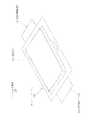
以下、本発明の電池モジュールの実施形態の一例について図面を参照しながら詳細に説明する。図1は、本例の電池モジュール1の外観斜視図である。図2は、電池モジュール2を構成している個々の電池セル2の分解斜視図である。図3及び図4は、電池モジュール1の分解斜視図である。 Hereinafter, an example of an embodiment of a battery module of the present invention will be described in detail with reference to the drawings. FIG. 1 is an external perspective view of the
図1に示すように、本例の電池モジュール1は、複数の電池セル2が保持部材3によって一体化(モジュール化)され、それら電池セル2が保持部材3に固定された導線部材(バスバー5)を介して直列接続されていることを特徴する。 As shown in FIG. 1, the
まず、電池セル2の構造について図2を参照しながら詳細に説明する。電池セル2とは、フィルム外装電池6が一つずつセルケース7に収容されたものである。フィルム外装電池6は、正極側活電極、負極側活電極、及び電解液を有する不図示の発電要素が2枚のラミネートフィルム8によって気密に包装されたものであり、出力電圧は約3.6[V]である。ラミネートフィルム8は、アルミニウムなどの金属フィルムと熱融着性の樹脂フィルムとを重ね合わせてなるフィルムであって、発電要素を包囲している上下2枚のラミネートフィルム8の対向する4辺は熱融着によって気密に封止されている。 First, the structure of the
フィルム外装電池6の発電要素には、セパレータを介して積層された正極側活電極と負極側活電極とからなる積層型と、帯状の正極側活電極と負極側活電極とをセパレータを介して重ねこれを捲回した後、扁平状に圧縮することによって正極側活電極と負極側活電極とを交互に積層させた捲回型とがあり、図2に示すフィルム外装電池6の発電要素は、上記積層型及び捲回型のいずれであってもよい。さらに、上記正極側活電極及び負極側活電極には、一般的なリチウムイオン二次電池において用いられている正極板及び負極板を用いることができる。すなわち、リチウム・マンガン複合酸化物、コバルト酸リチウム等の正極活物質をアルミニウム箔などの両面に塗布した正極板と、リチウムをドープ・脱ドープ可能な炭素材料を銅箔などの両面に塗布した負極板とを、セパレータを介して対向させ、それにリチウム塩を含む電解液を含浸させることによって上記発電要素を得ることができる。もっとも、発電要素は、正極、負極および電解質を含むものであればよく、通常の電池に用いられる任意の発電要素をそのまま、或いは適宜設計変更して適用可能である。 The power generation element of the film-
再び図2を参照すると、フィルム外装電池6の一方の短辺からは、上記正極側活電極に接続された正極用電極端子10が引き出され、他方の短辺からは、上記負極側活電極に接続された負極用電極端子11が引き出されている。正極用電極端子10及び負極用電極11の材料は、その電気的特性を考慮して選択されるが、本例では、正極用電極端子10にアルミニウム、負極用電極端子11に銅又はニッケルを用いた。 Referring to FIG. 2 again, the
セルケース7は、ケース本体12と枠体13とから構成されている。ケース本体12は、略枠状の形態を有する底板15と、底板15の周縁から立ち上げられた側壁16とを備え、側壁16の内側にフィルム外装電池6を収容可能な寸法を有する。一方、枠体13は、ケース本体12の側壁16の内側に嵌合可能な形状及び寸法を有し、ケース本体12に収容されたフィルム外装電池6の上に被せることによって、フィルム外装電池6の周縁を本体ケース12の底板15との間に挟持する。また、ケース本体12の底板15には、7個の貫通孔17が形成されている。これら貫通孔17は、ケース本体12内に収容されたフィルム外装電池6、及びそのフィルム外装電池6の上に被せられた枠体13と重複しない位置に形成されており、セルケース7をその厚み方向に連通するように設計されている。尚、セルケース7に収容されたフィルム外装電池6の正極用電極端子10及び負極用電極11は、ケース本体12の短辺に設けられている2つの切り欠き18を通してセルケース7の外部にそれぞれ引き出されている。 The
次に、図3及び図4を参照しながら保持部材3の構造について詳細に説明する。この保持部材3は、合成樹脂によって一体成形された仕切り部20と保持部21とから構成されている。仕切り部20は、図2に示すセルケース7と略相似の板状であって、一方の長辺部にその長手方向に沿って所定間隔で3つの通孔22が形成され、他方の長辺部に4つの通孔22が形成されている。一方、保持部21は、仕切り部20の四隅から通孔22の軸線方向前後に延在している。換言すれば、仕切り部20は、4つの保持部21によって囲まれた空間を保持部21の長手方向中央で二分することによって、第1の収容空間23と第2の収容空間25とを形成している。さらに、保持部21の内側面には、電池セル2(セルケース7)の角部が係合可能な係合溝26が長手方向に沿って形成され、該係合溝26の両端は、保持部21の端面27において開口している。また、保持部21の外側面には、補強のリブが多数形成されると共に、各電池セル2の電極端子10、11(図2)に装着されたバスバー5が固定される不図示の螺子穴が形成されている。 Next, the structure of the holding member 3 will be described in detail with reference to FIGS. 3 and 4. The holding member 3 includes a
以上のような構造を有する保持部材3を用いて複数の電池セル2を一体的に保持するには、次のようにする。まず、図3に示すように、12個の電池セル2をその厚み方向に積層させると共に、隣接する電池セル2の正極用電極端子10と負極用電極端子11とをバスバー5を介して接続して2つの電池セル群A、Bを形成する。ここで、各電池セル2の出力電圧は、約3.6[V]であるので、12個の電池セル2が直列接続された電池セル群A、Bの出力電圧は、約43.2[V]である。 In order to integrally hold the plurality of
次に、一方の電池セル群Aを保持部材3の第1の収容空間23内に収容し、他方の電池セル群Bを第2の収容空間25内に収容する。このとき、保持部21に形成されている係合溝26の案内に従って保持部21の端面27側から第1の収容空間23又は第2の収容空間25内に電池セル群A、Bを挿入する。この際、図4に示すように、仕切り部20の各通孔22に金属製のロッド30を予め貫通させておき、そのロッド30を第1の収容空間23及び第2の収容空間25にそれぞれ挿入される電池セル群A、Bの各セルケース7の貫通孔17(図2)に通す。 Next, one battery cell group A is accommodated in the first
再び図3を参照すると、第1の収容空間23及び第2の収容空間25内に電池セル群A、Bが収容されたら、各電池セル群A、Bの外側から貫通孔17に対応したボルト通し孔31が形成されている蓋板32を積層方向の最も外側の電池セル2に宛がう。この蓋板32は、仕切り部20と略相似の板状の形態を有し、四隅の角部を保持部21の端面27側から係合溝26に嵌合させることによって、電池セル群A、Bと同等に第1の収容空間23又は第2の収容空間25内に挿入可能である。ここで、仕切り部20の表面から保持部21の端面27までの距離Lは、積層された12個の電池セル2の厚みと蓋板32の厚みとの合計と略同一としてある。従って、第1及び第2の収容空間23、25内に収容された電池セル群A、Bの外側に蓋板32を上記のようにして宛がうと、蓋板32の表面と保持部21の端面27とが略面一となる(図1参照)。また、ロッド30の長さは、その端面が蓋板32の対応するボルト通し孔31の周縁に当接するに止まり、ボルト通し孔31には挿入されない長さに設定してある。そこで、図4に示すように、ボルト通し孔31に挿入したボルト33をロッド30の内周面に形成されている螺子に螺合させて、蓋板32を固定する。これによって、第1及び第2の収容空間23、25に収容された電池セル群A、Bが仕切り部20と蓋板32との間にそれぞれ挟持される。尚、ボルト33の締め付けトルクを調整することによって、電池セル群A、Bに作用する圧力を管理することができる。 Referring to FIG. 3 again, when the battery cell groups A and B are accommodated in the
電池セル群A、Bを構成する電池セル2の個数は12個に限定されるものではない。但し、電池セル群A、Bの出力電圧が50[V]以下となるように電池セル2の個数を設定することが安全性の観点からは望ましい。また、電池セル群A、Bを構成する電池セル2の個数を変更したり、個数は同一であっても各電池セル2の厚みを変更したりする場合には、これに応じて保持部21の長さを適宜変更することが望ましい。 The number of
本発明の電池モジュールは、これを複数直列又は並列接続することによって、所望の出電圧が得られる電池パック(組電池)を構成可能であることはこれまでの説明から自明である。例えば、本例の電池モジュール1を4個直列接続すれば、電動モータによって自動車を走行させるために必要とされる300[V]以上の電圧を出力可能な電気パック(組電池)が得られる。この場合、電池パックの組み立ての最終段階において各電池モジュール1内の電池セル群AとBとを電気接続し、さらに電池モジュール1同士を電気接続することが安全性の観点からは望ましい。何故なら、上記作業工程に従えば、電圧がなるべく低い状態でなるべく多くの作業工程を終えることができるからである。 It is obvious from the above description that the battery module of the present invention can constitute a battery pack (assembled battery) that can obtain a desired output voltage by connecting a plurality of them in series or in parallel. For example, if four
1 電池モジュール
2 電池セル
3 保持部材
5 バスバー
6 フィルム外装電池
7 セルケース
8 ラミネートフィルム
10 正極用電極端子
11 負極用電極端子
12 ケース本体
13 枠体
15 底板
16 側壁
17 貫通孔
18 切り欠き
20 仕切り部
21 保持部
22 通孔
23 第1の収容空間
25 第2の収容空間
26 係合溝
27 端面
30 ロッド
31 ボルト通し孔
32 蓋板
33 ボルト
A 電池セル群
B 電池セル群DESCRIPTION OF
Claims (8)
Translated fromJapanese厚み方向に積層された複数の前記電池セルを収容可能な第1の収容空間及び第2の収容空間と、
前記第1の収容空間と第2の収容空間とを前記電池セルの積層方向に隔てる仕切り部と、
前記第1及び第2の収容空間内に収容された前記電池セルの外面に当接し、前記積層方向と直交する方向への前記電池セルの移動を規制可能な保持部と、を有する電池セル保持部材。A battery cell holding member that integrally holds a plurality of battery cells in which a film-clad battery is housed in a cell case,
A first housing space and a second housing space capable of housing the plurality of battery cells stacked in the thickness direction;
A partition that separates the first housing space and the second housing space in the stacking direction of the battery cells;
A battery cell holder having a holding part that abuts on the outer surface of the battery cell housed in the first and second housing spaces and can regulate the movement of the battery cell in a direction orthogonal to the stacking direction. Element.
Priority Applications (1)
| Application Number | Priority Date | Filing Date | Title |
|---|---|---|---|
| JP2005000611AJP4708798B2 (en) | 2005-01-05 | 2005-01-05 | Battery cell holding member and battery module |
Applications Claiming Priority (1)
| Application Number | Priority Date | Filing Date | Title |
|---|---|---|---|
| JP2005000611AJP4708798B2 (en) | 2005-01-05 | 2005-01-05 | Battery cell holding member and battery module |
Publications (2)
| Publication Number | Publication Date |
|---|---|
| JP2006190530A JP2006190530A (en) | 2006-07-20 |
| JP4708798B2true JP4708798B2 (en) | 2011-06-22 |
Family
ID=36797533
Family Applications (1)
| Application Number | Title | Priority Date | Filing Date |
|---|---|---|---|
| JP2005000611AExpired - LifetimeJP4708798B2 (en) | 2005-01-05 | 2005-01-05 | Battery cell holding member and battery module |
Country Status (1)
| Country | Link |
|---|---|
| JP (1) | JP4708798B2 (en) |
Families Citing this family (8)
| Publication number | Priority date | Publication date | Assignee | Title |
|---|---|---|---|---|
| JP4283833B2 (en)* | 2006-09-06 | 2009-06-24 | 日立ビークルエナジー株式会社 | Secondary battery module |
| KR101080123B1 (en) | 2007-07-23 | 2011-11-04 | 주식회사 엘지화학 | Battery Module Assembly |
| JP5734450B2 (en)* | 2010-11-22 | 2015-06-17 | エルジー・ケム・リミテッド | Small structure battery pack |
| KR101305224B1 (en)* | 2010-12-28 | 2013-09-12 | 주식회사 엘지화학 | Battery Module and Battery Pack Comprising the Same |
| KR101305218B1 (en)* | 2010-12-28 | 2013-09-12 | 주식회사 엘지화학 | Battery Module Having Fixing Member and Coupling Member, and Battery Pack Employed with the Same |
| KR101298872B1 (en) | 2011-12-28 | 2013-08-21 | 에이치엘그린파워 주식회사 | Housing structure of Battery module |
| CN105957990A (en)* | 2016-07-01 | 2016-09-21 | 奇瑞汽车股份有限公司 | Automobile power battery pack frame |
| US11784360B2 (en)* | 2019-05-14 | 2023-10-10 | Sk On Co., Ltd. | Battery module |
Family Cites Families (2)
| Publication number | Priority date | Publication date | Assignee | Title |
|---|---|---|---|---|
| JP4965012B2 (en)* | 1999-12-15 | 2012-07-04 | トヨタ自動車株式会社 | Battery pack for vehicles |
| JP2004055348A (en)* | 2002-07-19 | 2004-02-19 | Nissan Motor Co Ltd | Battery pack, composite battery pack and vehicle |
- 2005
- 2005-01-05JPJP2005000611Apatent/JP4708798B2/ennot_activeExpired - Lifetime
Also Published As
| Publication number | Publication date |
|---|---|
| JP2006190530A (en) | 2006-07-20 |
Similar Documents
| Publication | Publication Date | Title |
|---|---|---|
| KR100859538B1 (en) | Storage battery device | |
| JP4757508B2 (en) | Electrical device assembly | |
| JP6752674B2 (en) | Battery pack | |
| US11158895B2 (en) | Battery module, battery pack including battery module, and vehicle including battery pack | |
| JP5338125B2 (en) | Battery pack | |
| JP5022222B2 (en) | Insulating cover and film-covered electrical device assembly | |
| US10236487B2 (en) | Battery module | |
| KR20070116295A (en) | High capacity battery cell containing two or more unit cells | |
| JP4944374B2 (en) | Electrical device assembly | |
| JP5444379B2 (en) | Storage member, storage case and battery pack | |
| JP2012146681A (en) | Electric device aggregation | |
| JP2006253060A (en) | Film exterior electrical device assembly | |
| JP4955398B2 (en) | Electrical device assembly | |
| JP4708798B2 (en) | Battery cell holding member and battery module | |
| JP4698215B2 (en) | Electrical device assembly and storage box structure | |
| JP2009224227A (en) | Battery module and battery pack with the same | |
| KR101472882B1 (en) | Battery Module Having Cell Cover Coupling Portion and Receiving Part Coupling Portion | |
| JP4784067B2 (en) | Power storage module | |
| WO2016084273A1 (en) | Power source device | |
| JP5248781B2 (en) | Electrical device module and electrical device module assembly | |
| JP4787509B2 (en) | Electrical device assembly | |
| JP4955399B2 (en) | Film exterior electrical device assembly |
Legal Events
| Date | Code | Title | Description |
|---|---|---|---|
| A711 | Notification of change in applicant | Free format text:JAPANESE INTERMEDIATE CODE: A711 Effective date:20060612 | |
| A711 | Notification of change in applicant | Free format text:JAPANESE INTERMEDIATE CODE: A711 Effective date:20070109 | |
| A621 | Written request for application examination | Free format text:JAPANESE INTERMEDIATE CODE: A621 Effective date:20071214 | |
| A977 | Report on retrieval | Free format text:JAPANESE INTERMEDIATE CODE: A971007 Effective date:20110304 | |
| TRDD | Decision of grant or rejection written | ||
| A01 | Written decision to grant a patent or to grant a registration (utility model) | Free format text:JAPANESE INTERMEDIATE CODE: A01 Effective date:20110309 | |
| A61 | First payment of annual fees (during grant procedure) | Free format text:JAPANESE INTERMEDIATE CODE: A61 Effective date:20110317 | |
| R150 | Certificate of patent or registration of utility model | Ref document number:4708798 Country of ref document:JP Free format text:JAPANESE INTERMEDIATE CODE: R150 | |
| S531 | Written request for registration of change of domicile | Free format text:JAPANESE INTERMEDIATE CODE: R313531 | |
| R350 | Written notification of registration of transfer | Free format text:JAPANESE INTERMEDIATE CODE: R350 | |
| S111 | Request for change of ownership or part of ownership | Free format text:JAPANESE INTERMEDIATE CODE: R313117 | |
| R350 | Written notification of registration of transfer | Free format text:JAPANESE INTERMEDIATE CODE: R350 | |
| EXPY | Cancellation because of completion of term |