JP4708680B2 - Image insertion device for compressed moving image data - Google Patents
Image insertion device for compressed moving image dataDownload PDFInfo
- Publication number
- JP4708680B2 JP4708680B2JP2003091243AJP2003091243AJP4708680B2JP 4708680 B2JP4708680 B2JP 4708680B2JP 2003091243 AJP2003091243 AJP 2003091243AJP 2003091243 AJP2003091243 AJP 2003091243AJP 4708680 B2JP4708680 B2JP 4708680B2
- Authority
- JP
- Japan
- Prior art keywords
- image
- compressed moving
- moving image
- image data
- image insertion
- Prior art date
- Legal status (The legal status is an assumption and is not a legal conclusion. Google has not performed a legal analysis and makes no representation as to the accuracy of the status listed.)
- Expired - Fee Related
Links
Images


Classifications
- H—ELECTRICITY
- H04—ELECTRIC COMMUNICATION TECHNIQUE
- H04N—PICTORIAL COMMUNICATION, e.g. TELEVISION
- H04N19/00—Methods or arrangements for coding, decoding, compressing or decompressing digital video signals
- H04N19/10—Methods or arrangements for coding, decoding, compressing or decompressing digital video signals using adaptive coding
- H04N19/134—Methods or arrangements for coding, decoding, compressing or decompressing digital video signals using adaptive coding characterised by the element, parameter or criterion affecting or controlling the adaptive coding
- H04N19/157—Assigned coding mode, i.e. the coding mode being predefined or preselected to be further used for selection of another element or parameter
- H04N19/159—Prediction type, e.g. intra-frame, inter-frame or bidirectional frame prediction
- H—ELECTRICITY
- H04—ELECTRIC COMMUNICATION TECHNIQUE
- H04N—PICTORIAL COMMUNICATION, e.g. TELEVISION
- H04N19/00—Methods or arrangements for coding, decoding, compressing or decompressing digital video signals
- H04N19/46—Embedding additional information in the video signal during the compression process
- H04N19/467—Embedding additional information in the video signal during the compression process characterised by the embedded information being invisible, e.g. watermarking
- H—ELECTRICITY
- H04—ELECTRIC COMMUNICATION TECHNIQUE
- H04N—PICTORIAL COMMUNICATION, e.g. TELEVISION
- H04N19/00—Methods or arrangements for coding, decoding, compressing or decompressing digital video signals
- H04N19/48—Methods or arrangements for coding, decoding, compressing or decompressing digital video signals using compressed domain processing techniques other than decoding, e.g. modification of transform coefficients, variable length coding [VLC] data or run-length data
Landscapes
- Engineering & Computer Science (AREA)
- Multimedia (AREA)
- Signal Processing (AREA)
- Compression Or Coding Systems Of Tv Signals (AREA)
- Compression, Expansion, Code Conversion, And Decoders (AREA)
- Studio Circuits (AREA)
Description
Translated fromJapanese【0001】
【発明の属する技術分野】
この発明は圧縮動画像データの画像挿入装置に関し、特に動画像データ中にロゴ画像を高速かつ高効率で挿入する圧縮動画像データの画像挿入装置に関する。
【0002】
【従来の技術】
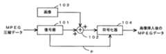
圧縮動画像データ中に画像を挿入する従来方式の一つとして、例えば、図11に示されているようなベースバンドでの画像挿入方式がある。該従来方式の動作を説明すると、復号器101は、一旦、入力信号であるMPEG圧縮データを1フレーム分全て復号する。次いで、合成器102で挿入されるべき画像103を前記復号画像に挿入し、符号化器104で再圧縮する。この際、復号器101で復号された入力データの符号化情報p、たとえば動き情報MVや符号化タイプ等の情報が符号化器104に送られ、該符号化器104においてそのまま利用される。符号化器104からは、画像挿入後のMPEGデータが出力される。
【0003】
上記の従来方式によれば、画質劣化を殆ど生ずることなくロゴ画像などの画像103を入力画像に挿入することができるが、符号化器104で再度符号化するため、入力データの符号化情報pを使用しても、全体の処理量が大きく、処理コストが非常に大きいという問題があった。
【0004】
画像挿入の他の従来方式として、例えば特開2001−268572号公報に記されているような、ロゴ画像を圧縮データ上で挿入する方式がある。この方式は、符号化されたビットストリームを受信するステップと、該ビットストリームを部分的に復号化するステップと、該部分的に復号化されたビットストリーム中にビジュアル要素を挿入するステップと、該ビジュアル要素が挿入されたビットストリームを再符号化するステップと、該再符号化されたビットストリームを出力するステップとからなるものである。
【0005】
この方式によれば、符号化されたビットストリームを部分的に復号化するだけであるので、全体の処理量を削減できる。
【0006】
【発明が解決しようとする課題】
しかしながら、前記ロゴ画像を圧縮データ上で挿入する従来方式では、ロゴ挿入フレームが双方向予測フレーム(Bフレーム)で開始する場合、該開始フレームのロゴ領域と非ロゴ領域とを同様にフレーム間予測で再符号化するため、フレーム間符号化効率が低いロゴ領域もフレーム間符号化されることになり、符号化効率が劣化する可能性がある。なお、該開始フレームのフレーム間符号化効率が低い理由は、該開始フレーム以前のフレームにはロゴが入っていないので、ロゴ領域のフレーム間相関が非常に小さいためである。
【0007】
また、ロゴ画像と元の画像の合成割合によらず符号化するため、ロゴ画像の合成比率が高い場合(例えば、濃いロゴ画像を合成する場合)、元の画像のようにフレーム間予測による符号化を用いると符号化効率が劣化する可能性がある。
【0008】
なお、前記の問題を解消するために、前記ロゴ開始フレームである双方向予測フレーム(Bフレーム)に代えてイントラフレームを用いると、双方向予測フレームに対するビット配分が少ないにも拘わらず、ビット量が大きいイントラ符号化が用いられることになり、イントラ符号化に必要なビット量が不足し、画質が劣化するという問題が発生する。
【0009】
本発明の目的は、前記した従来技術の課題を解決し、画像例えばロゴ画像を高速かつ高効率で挿入できる圧縮動画像データの画像挿入装置を提供することにある。他の目的は、ロゴ挿入を双方向予測フレームから開始しなければならなくなった場合においても、画質劣化を起こすことなく再符号化できる圧縮動画像データの画像挿入装置を提供することにある。
【0010】
【課題を解決するための手段】
前記した目的を達成するために、本発明は、入力動画像データを部分復号する部分復号手段と、該部分復号手段により部分復号されたデータの一部に画像を挿入する画像挿入手段と、該画像挿入手段により挿入された画像挿入領域を部分圧縮する部分符号化手段と、該部分符号化手段で再圧縮されたデータのビット量を目的のビット量に制御するレート制御手段とを具備し、前記画像挿入手段は、任意の合成比率により画像を挿入し、前記部分符号化手段は、前記画像の挿入を開始する画像挿入開始フレームにおける画像挿入領域の符号化モードを、該画像挿入開始フレームのピクチャタイプにより決定し、該画像挿入開始フレームがイントラ符号化フレーム又は前予測インター符号化フレームの場合は、前記画像挿入領域をイントラ符号化し、該画像挿入開始フレームが双方向予測符号化フレームの場合は、前記画像挿入開始フレームにおける画像挿入領域はインターフレーム符号化を行い、該画像挿入開始フレームが参照可能なフレームにおいて該画像挿入領域をイントラ符号化するようにした点に第1の特徴がある。この特徴によれば、元画像の一部分に、高速かつ高効率で画像、例えばロゴ画像を挿入することができるようになる。
【0011】
また、本発明は、画像挿入開始フレーム全体の符号化モードが双方向予測符号化フレームである時には、画像挿入領域はインターフレーム符号化を行い、該画像挿入開始フレームが参照可能なフレームにおいて該画像挿入領域をイントラ符号化するようにした点に第2の特徴がある。この特徴によれば、画像挿入開始フレーム全体の符号化モードが双方向予測符号化フレームであっても、ビット量の不足を招くことなく、画像挿入部分を高速かつ高効率で再圧縮することができる。このため、画質劣化を生じることなく画像挿入部分を高速かつ高効率で再圧縮することができる。
【0012】
また、本発明は、前記部分符号化手段において行われる量子化は、インターフレーム符号化された変換係数を部分的に復号して動き補償予測し、該動き補償予測後に変換した変換係数を量子化して用いるようにした点に第3の特徴がある。この特徴によれば、画像挿入部分に生ずる画像歪みを極力低減することができるようになる。
【0013】
【発明の実施の形態】
以下に、図面を参照して、本発明を詳細に説明する。図1は、本発明の一実施形態の全体構成を概略的に示すブロック図である。
【0014】
入力データであるMPEG圧縮データは、部分復号部1とロゴ挿入制御部8に入力する。部分復号部1は、例えば、図2に示されているように、可変長復号部(VLD)10と逆量子化部11から構成され、ブロックDCT係数aを出力すると共に、動きベクトルMV,符号化タイプ、量子化パラメータQPなどの符号化情報bを分離して出力する。
【0015】
一方、前記ロゴ挿入制御部8は、後述のロゴ挿入領域分離部2、ロゴ情報挿入部3、ロゴ情報供給部4、ロゴ領域部分符号化部5、および非ロゴ領域部分符号化部6の動作を制御する。なお、該ロゴ領域部分符号化部5および非ロゴ領域部分符号化部6の制御動作の詳細については、図5を参照して後述する。レート制御部7は画面の複雑度に応じたレート制御を行い、前記ロゴ領域部分符号化部5と非ロゴ領域部分符号化部6で部分再圧縮されたデータのビット量を目的のビット量に制御する。
【0016】
レート制御部7では画面の複雑度に応じたレート制御を行うことが可能であるが、画面の複雑度として画面内の偏差などの複雑度計算を行う代わりに部分復号部1から得られる量子化情報を用いて複雑度情報として利用することが可能である。例えば、量子化ステップが高い程複雑度が高いと判定してレート制御に利用することができる。
【0017】
次に、前記部分復号部1から出力されたブロックDCT係数aはロゴ挿入領域分離部2で、ロゴ挿入領域DCT係数cと非ロゴ挿入領域DCT係数dとに分けられる。ロゴ挿入領域DCT係数cはロゴ情報挿入部3に送られ、非ロゴ挿入領域DCT係数dは非ロゴ領域部分符号化部6に送られる。
【0018】
挿入されるロゴ情報は、ロゴ情報供給部4から供給される。該ロゴ情報供給部4は、図3に示されているように、例えばロゴデータ31をDCT変換するDCT部32と、該DCT変換されたロゴのDCT係数を記憶するメモリ33とから構成されている。したがって、該メモリ33からは、ロゴ挿入制御部8からの指示に従って、ロゴ画像のDCT係数eが出力される。
【0019】
図1のロゴ情報挿入部3は、図4に示されているように、例えば合成部41から構成されており、該合成部41は、ロゴ挿入領域DCT係数cとロゴ画像DCT係数eとを合成する。このとき、ロゴ挿入制御部8から指示される重み係数(または、合成比率)α(0≦α≦1)を考慮に入れて合成する。
【0020】
この場合、ロゴ領域DCT係数LA(u,v)とロゴDCT係数LG(u,v)が合成され、ロゴ挿入DCT係数LI(u,v)は次のようになる。
【0021】
LI(u,v)=α×LG(u,v)+(1−α)×LA(u,v)
【0022】
例えば、元画像のロゴ挿入領域を100%ロゴ画像DCT係数eに置き換えるのであればα=1、半分の濃さに置き換えるのであればα=0.5とされる。該ロゴ情報挿入部3は、ロゴ挿入DCT係数fを出力する。なお、合成部41で合成するDCT係数は、直流成分のみ、あるいは直流成分+低周波成分のみであってもよい。
【0023】
次に、ロゴ領域部分符号化部5には、該ロゴ挿入DCT係数fと符号化情報bが入力し、前記ロゴ挿入制御部8からの制御に従ってロゴ挿入領域を符号化する。一方、非ロゴ領域部分符号化部6には非ロゴ挿入領域DCT係数dと符号化情報bが入力し、非ロゴ領域と非ロゴ挿入フレームとを符号化する。
【0024】
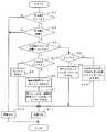
以下に、前記ロゴ挿入制御部8の前記ロゴ領域部分符号化部5と非ロゴ領域部分符号化部6とに対する制御動作を、図5のフローチャートを参照して説明する。
【0025】
ステップS1では、入力してきたMPEG圧縮データがロゴ挿入フレームであるか否かの判断がなされ、肯定であればステップS2に進む。ステップS2では、ロゴ挿入領域か否かの判断がなされる。この判断が肯定の場合にはステップS3に進むが、前記ステップS1およびS2のいずれかが否定の時にはステップS12に進む。ステップS12では、図10で後述する再量子化がなされる。
【0026】
ステップS3では、該ロゴ挿入フレームがロゴ画像挿入の開始フレームであるか否かの判断がなされる。この判断が肯定の時にはステップS4に進んで、該開始フレームはIまたはPピクチャであるか否かの判断がなされる。この判断が肯定の時にはステップS5に進んで、ロゴ挿入領域をイントラ符号化する指示が出力される。一方、否定の時、すなわちBピクチャの時にはステップS6に進んで、後続の参照フレームのロゴ挿入領域をイントラ符号化する指示が出される。ステップS7では、該後続の参照フレームを用いて、現フレームのロゴ挿入領域をインター符号化する指示が出力される。
【0027】
前記ステップS3の判断が否定の時、すなわちロゴ挿入フレームがロゴ挿入開始フレームでない時にはステップS8に進んで、前記重み係数αが予め定められている閾値Thより大きいか否かの判断がなされる。この判断が肯定の場合、すなわちロゴ画像の重みが大きい場合には、ステップS9に進んで動きベクトルMVを0にして、ロゴ挿入領域をインターフレーム符号化する指示が出力される。これは、ロゴ画像は一般に動きのない静止画像であるので、ロゴ画像の重みが大きいということはロゴ挿入領域の画像の動きが小さいまたは零と考えられるからである。
【0028】
一方、ステップS8の判断が否定の時には、合成される元の動画像の割合が大きいので、ロゴ挿入領域の画像の動きが大きいと考えられる。このため、ステップS10において、入力MPEGデータの動きベクトルMV、すなわち前記符号化情報b中の動きベクトルMVを再利用して、ロゴ挿入領域をインターフレーム符号化を行う。これにより、処理量を低減して処理の高速化を図ることができるようになる。前記ステップS5、S7、S9およびS10の符号化の後は、ステップS11に進み再量子化が行われる。この再量子化は、図7または図8で後述する方式で行われる。
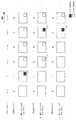
【0029】
図6は、前記ステップS4〜S7の動作を示したものである。同図(a)および(c)に示されているように、ロゴ挿入の開始フレーム、つまりロゴ挿入の第1フレームがIまたはPピクチャの時には、該第1フレームのロゴ挿入領域cはイントラ符号化される。一方、同図(b)に示されているように、前記第1フレームがBピクチャの時には、後続の参照フレームであるPピクチャのロゴ挿入領域c’がイントラ符号化され、前記第1フレームであるBピクチャのロゴ挿入領域cは該Pピクチャのロゴ挿入領域c’を用いてインター符号化される。
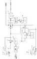
【0030】
図7は、前記ロゴ領域部分符号化部5の1実施例を示す機能ブロック図である。スイッチング部70a、70bは前記ロゴ挿入制御部8からの制御情報により制御される。すなわち、制御情報z1がイントラ符号化の時にはスイッチング部70aは端子X1を選択し、インターフレーム符号化の時には端子X2を選択する。一方、制御情報z2が図5のステップS9の時すなわちMV=0の時にはスイッチング部70bは端子Y1を、ステップS9以外の時すなわち入力MPEGデータのMVを再利用する時には端子Y2を選択する。
【0031】
上記の動作により、イントラ符号化の時にはロゴ挿入DCT係数fは再量子化部72で再量子化され、可変長符号化部73で符号化されてMPEG符号化データとして出力される。
【0032】
一方、インターフレーム符号化の時には、減算部71にロゴ挿入DCT係数fが入力し、減算部71はロゴ挿入DCT係数fからDCT係数80を減算する。減算部71から出力されるDCT予測誤差係数は再量子化部72でレート制御部7(図1参照)からのレート制御情報に従って再量子化され、可変長符号化部73で符号化されてMPEG符号化データとして出力される。
【0033】
一方、前記再量子化部72で再量子化されたデータは逆量子化部74にも入力し、逆量子化される。次いで、減算部75は、該逆量子化されたDCT係数から前記DCT予測誤差係数を減算する。この減算により、該DCT予測誤差係数の量子化誤差が得られる。該量子化誤差は逆DCT部76で逆DCT化され、加算部77で、動き補償部78で補償された画像データと加算される。前記動き補償部78は、前記スイッチング部70bから供給される符号化情報に基づいて動き補償する。ロゴ合成比率がある閾値よりも大きい場合はロゴ画像の強度が高くなり、またロゴ画像は静止しているため、動き補償予測は動き量MV=0として符号化を行う。これに対して、α値が小さい場合は、元の画像の割合が高いと考えられるため、元のMPEGデータ中の動き補償予測をそのまま用いる。この場合、前記重み係数α>ThであればMV=0が、α≦Thであれば部分復号部1からの符号化情報bが、動き補償部78に供給される。メモリ79は該動き補償部78の動作に使用されるものである。該動き補償部78で動き補償された後に変換されたDCT係数80は前記減算部71に供給される。
【0034】
この再量子化によれば、前記減算部71で再量子化の歪み成分が低減されるので、ロゴ挿入領域の再量子化ノイズをより低減して、ロゴ挿入領域の再量子化を行えるようになる。
【0035】
また、図7からも分かるように、符号化情報bから得られる動き情報を用いて動き補償を行っているため、動画像符号化処理で処理負荷の高い動き探索処理が不要になるため、高速な符号化処理を実現することができる。
【0036】
図7で、再量子化部72はレート制御情報を用いて再量子化を行うことができる。この場合、レート制御情報から得られる配分ビット量を基に量子化ステップを決定して再量子化を行うことができる。また、配分ビット量を決定する際に、画面の複雑度を用いることができるが、先に述べたように、画面の複雑度として入力圧縮動画像を部分復号して得られる量子化情報から局所的、画面全体の複雑度を予測して利用することも可能で、これにより、画面の偏差測定などの処理を削減することが可能となる。
【0037】
ただし、例えば、元の画像のコントラストが高く、ロゴ画像のコントラストが低い場合はロゴ合成比率が高くても元の画像の影響が高くなるため、前述の動き量MV=0にするよりも元のMPEGデータ中の動き補償予測をそのまま用いた方が符号化効率を高めることができる。逆にロゴ画像のコントラストが高く、元の画像のコントラストが低い場合は、ロゴ合成比率が低くてもロゴ画像の強度が高くなるため、動き量MV=0として符号化を行った方が符号化効率を高められる可能性がある。したがって、このような場合は、挿入後の画像の符号化量が小さくなるように適応的に動き補償予測を行うことが望ましい。
【0038】
このためには、これら2つの方法を比較して符号量の小さくなる予測方法を選択することができる。この場合、ロゴ挿入後の画像の動き補償予測誤差量を比較する。比較の方法としては、図8に示すような図5の変形例を用いることができる。この場合、動き補償予測誤差のDCT係数量を動き補償予測誤差量として用いる。一例としてMV=0とした時のDCT係数量をNDO、元の動き補償予測を用いた場合のDCT係数量をNDMとしてNDOがNDMより小さい場合にMV=0として符号化し、逆の場合には元の動き補償予測を用いる。DCT係数量としては、ブロック内の0でないDCT係数の個数やDCT係数の絶対値和を用いることができる。
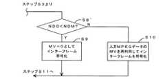
【0039】
ここに、図8は、図5の変形例の要部のフローチャートを示し、図9は該図8の動作を実現するための前記ロゴ領域部分符号化部5の機能ブロック図を示す。なお、図8において、図5と同一ステップは図示を省略されている。また、図9において、図7と同一または同等物には同じ符号が付されている。
【0040】
図8が図5と違うところは、ステップS8’のみであり、他の処理は同一である。すなわち、ステップS8’では、図9の係数カウンタ81のカウント値(DCT係数量)NDOが前記NDMより小さいか否かの判断がなされる。そして、この判断が肯定の時にはステップS9に進んで動きベクトルMVを0としてインターフレーム符号化を行う。一方、否定の時にはステップS10に進んで入力MPEGデータの動きベクトルMVを再利用してインターフレーム化を行う。
【0041】
ここに、前記計数カウンタ81は予測誤差情報量であるDCT係数80をカウントするものであり、ステップS8’のNDO<NDMが成立するということは予測誤差情報量のDCT係数が小さい、つまり画像の動きが小さいということであるから、動きベクトルMVを強制的に0にして処理量を軽減する。逆に、NDO<NDMが不成立であるということは、予測誤差情報量のDCT係数が大きい、つまり画像の動きが大きいということであるから、動きベクトルMVとして入力MPEGデータの動きベクトルMVを再利用する。なお、図9のロゴ領域部分符号化部5においても、前記図5の制御を使用できることは明らかである。
【0042】
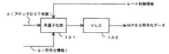
次に、図10は、図1の非ロゴ領域部分符号化部6または前記ステップS12(図5参照)の再符号化を示すものである。該非ロゴ領域部分符号化部6は、前記符号化情報bの量子化パラメータQPを再利用したり、レート制御部7からのレート制御情報を再利用したりして、ブロックDCT係数dを再量子化する再量子化部101と、可変長符号化部(VLC)102からなる。該再量子化部101は、ロゴ挿入フレームでない場合は、前記符号化情報bの量子化パラメータQPを再利用し、ロゴ挿入フレームであるがロゴ挿入領域でない画像には前記レート制御情報に従って再量子化するのが好適である。これは、ロゴの挿入により、符号化におけるビット配分が変動するためである。
【0043】
なお、変形例として、上記量子化はロゴ領域にも同様に利用することができる。ただし、インター符号化の場合、量子化に伴う誤差雑音が累積する可能性がある。
【0044】
前記した実施形態では、入力データがMPEG圧縮データである場合、またロゴ画像を例にして説明したが、本発明はこれに限定されず他の圧縮方式で圧縮されたデータである場合あるいはロゴ画像以外の画像にも適用することができる。
【0045】
また、前記の実施形態ではMPEG方式について説明したが、これに限るものではない。ベクトル量子化やウェーブレット変換などの量子化符号化や変換符号化方式においても利用できる。
【0046】
【発明の効果】
以上の説明から明らかなように、本発明によれば、小さな処理量で、元画像の一部分に、画像例えばロゴ画像を挿入することができるようになる。
【0047】
また、本発明によれば、画像挿入開始フレーム全体の符号化モードが双方向予測符号化フレームであっても、ビット量の不足を招くことなく、また画質の劣化を招くことなく、画像挿入部分を高速かつ高効率で再圧縮することができるようになる。
【0048】
また、本発明によれば、画像挿入部分の画質劣化を招くことなく、画像挿入部分を再圧縮することができるようになる。
【図面の簡単な説明】
【図1】 本発明の一実施形態の概略の構成を示すブロック図である。
【図2】 図1の部分復号部の一具体例を示すブロック図である。
【図3】 図1のロゴ情報供給部の一具体例を示すブロック図である。
【図4】 図1のロゴ情報挿入部の一具体例を示すブロック図である。
【図5】 本実施形態の要部の動作を説明するフローチャートである。
【図6】 図5のステップS4〜S7の処理の説明図である。
【図7】 図1のロゴ領域部分符号化部の一具体例を示すブロック図である。
【図8】 図5の変形例の変形部分のみを示すフローチャートである。
【図9】 図1のロゴ領域部分符号化部の他の具体例を示すブロック図である。
【図10】 図1の非ロゴ領域部分符号化部の一具体例を示すブロック図である。
【図11】 従来装置の一例の構成を示すブロック図である。
【符号の説明】
1・・・部分復号部、2・・・ロゴ挿入領域分離部、3・・・ロゴ情報挿入部、4・・・ロゴ情報供給部、5・・・ロゴ領域部分符号化部、6・・・非ロゴ領域部分符号化部、7・・・レート制御部、8・・・ロゴ挿入制御部。[0001]
BACKGROUND OF THE INVENTION
The present invention relates to an image insertion device for compressed moving image data, and more particularly to an image insertion device for compressed moving image data that inserts a logo image into moving image data at high speed and high efficiency.
[0002]
[Prior art]
As one of the conventional methods for inserting an image into compressed moving image data, for example, there is a baseband image insertion method as shown in FIG. Explaining the operation of the conventional method, the
[0003]
According to the conventional method, an
[0004]
As another conventional method of inserting an image, there is a method of inserting a logo image on compressed data as described in, for example, Japanese Patent Application Laid-Open No. 2001-268572. The scheme includes receiving an encoded bitstream, partially decoding the bitstream, inserting a visual element in the partially decoded bitstream, and The method includes a step of re-encoding the bit stream in which the visual element is inserted and a step of outputting the re-encoded bit stream.
[0005]
According to this method, since the encoded bit stream is only partially decoded, the overall processing amount can be reduced.
[0006]
[Problems to be solved by the invention]
However, in the conventional method of inserting the logo image on the compressed data, when the logo insertion frame starts with a bidirectional prediction frame (B frame), the logo area and non-logo area of the start frame are similarly predicted between frames. Therefore, a logo region having low interframe coding efficiency is also interframe coded, which may degrade the coding efficiency. The reason why the interframe coding efficiency of the start frame is low is that no logo is contained in the frames before the start frame, and therefore, the interframe correlation of the logo area is very small.
[0007]
In addition, since the encoding is performed regardless of the combination ratio of the logo image and the original image, when the combination ratio of the logo image is high (for example, when combining a dark logo image), the encoding by inter-frame prediction like the original image is performed. If encoding is used, encoding efficiency may be degraded.
[0008]
In order to solve the above problem, if an intra frame is used instead of the bidirectional prediction frame (B frame) that is the logo start frame, the bit amount is small even though the bit allocation to the bidirectional prediction frame is small. Intra-encoding with a large value is used, and there is a problem that the amount of bits necessary for intra-encoding is insufficient and the image quality deteriorates.
[0009]
An object of the present invention is to solve the above-described problems of the prior art and to provide an image insertion device for compressed moving image data capable of inserting an image, for example, a logo image at high speed and high efficiency. Another object is to provide an image insertion device for compressed video data that can be re-encoded without causing image quality degradation even when logo insertion has to be started from a bidirectional prediction frame.
[0010]
[Means for Solving the Problems]
In order to achieve the above object, the present invention includes a partial decoding unit that partially decodes input moving image data, an image insertion unit that inserts an image into a part of data partially decoded by the partial decoding unit, Partial encoding means for partially compressing the image insertion area inserted by the image insertion means, and rate control means for controlling the bit amount of the data recompressed by the partial encoding means to a target bit amount, The image insertion means inserts an image at an arbitrary composition ratio, and the partial encoding means sets the encoding mode of the image insertion area in the image insertion start frame for starting the insertion of the image to the image insertion start frame.determined by the picturetype, if the image insertion start frame is intra-coded frame or forward prediction inter-coded frame, intra-coded the image insertion area When the image insertion start frame is a bidirectional predictive coding frame, the image insertion area in the image insertion start frame is subjected to interframe coding, and the image insertion area is referred to in the frame that can be referred to by the image insertion start frame. there is first characterized in that so as tointra-coding. According to this feature, an image such as a logo image can be inserted into a part of the original image at high speed and high efficiency.
[0011]
In the present invention, when the coding mode of the entire image insertion start frame is a bi-directional predictive coding frame, the image insertion area performs inter-frame coding, and the image is inserted in a frame that can be referred to by the image insertion start frame. The second feature is that the insertion region is intra-coded. According to this feature, even if the encoding mode of the entire image insertion start frame is a bidirectional predictive encoding frame, the image insertion portion can be recompressed at high speed and with high efficiency without causing a shortage of bit amount. it can. For this reason, the image insertion portion can be recompressed at high speed and with high efficiency without causing image quality degradation.
[0012]
In the present invention, the quantization performed in the partial encoding means is performed by partially decoding the inter-frame encoded transform coefficient to perform motion compensation prediction, and quantizing the transformed transform coefficient after the motion compensation prediction. The third feature is that they are used. According to this feature, it is possible to reduce image distortion generated in the image insertion portion as much as possible.
[0013]
DETAILED DESCRIPTION OF THE INVENTION
Hereinafter, the present invention will be described in detail with reference to the drawings. FIG. 1 is a block diagram schematically showing the overall configuration of an embodiment of the present invention.
[0014]
MPEG compressed data as input data is input to the
[0015]
On the other hand, the logo
[0016]
The
[0017]
Next, the block DCT coefficient a output from the
[0018]
The logo information to be inserted is supplied from the logo
[0019]
As shown in FIG. 4, the logo
[0020]
In this case, the logo area DCT coefficient LA (u, v) and the logo DCT coefficient LG (u, v) are combined, and the logo insertion DCT coefficient LI (u, v) is as follows.
[0021]
LI (u, v) = α × LG (u, v) + (1−α) × LA (u, v)
[0022]
For example, if the logo insertion area of the original image is replaced with the 100% logo image DCT coefficient e, α = 1, and if it is replaced with half the darkness, α = 0.5. The logo
[0023]
Next, the logo insertion DCT coefficient f and the encoding information b are input to the logo region
[0024]
Below, the control operation | movement with respect to the said logo area | region
[0025]
In step S1, it is determined whether or not the input MPEG compressed data is a logo insertion frame. If the result is affirmative, the process proceeds to step S2. In step S2, it is determined whether or not it is a logo insertion area. If this determination is affirmative, the process proceeds to step S3. If either of the steps S1 and S2 is negative, the process proceeds to step S12. In step S12, requantization described later with reference to FIG. 10 is performed.
[0026]
In step S3, it is determined whether the logo insertion frame is a logo image insertion start frame. When this determination is affirmative, the routine proceeds to step S4, where it is determined whether or not the start frame is an I or P picture. When this determination is affirmative, the process proceeds to step S5, and an instruction to intra-code the logo insertion area is output. On the other hand, when the result is negative, that is, when the picture is a B picture, the process proceeds to step S6, where an instruction to intra-code the logo insertion area of the subsequent reference frame is issued. In step S7, an instruction to inter-code the logo insertion area of the current frame is output using the subsequent reference frame.
[0027]
When the determination in step S3 is negative, that is, when the logo insertion frame is not a logo insertion start frame, the process proceeds to step S8 to determine whether or not the weighting factor α is greater than a predetermined threshold Th. If this determination is affirmative, that is, if the weight of the logo image is large, the process proceeds to step S9, where the motion vector MV is set to 0, and an instruction to inter-frame encode the logo insertion area is output. This is because a logo image is generally a still image with no movement, and thus a large weight of the logo image is considered to be a small or zero movement of the image in the logo insertion area.
[0028]
On the other hand, when the determination in step S8 is negative, since the ratio of the original moving image to be synthesized is large, it is considered that the movement of the image in the logo insertion area is large. Therefore, in step S10, the motion vector MV of the input MPEG data, that is, the motion vector MV in the encoded information b is reused, and the logo insertion area is inter-frame encoded. As a result, the processing amount can be reduced and the processing speed can be increased. After the encoding in steps S5, S7, S9, and S10, the process proceeds to step S11 and requantization is performed. This requantization is performed by the method described later with reference to FIG.
[0029]
FIG. 6 shows the operation of steps S4 to S7. As shown in FIGS. 4A and 4C, when the logo insertion start frame, that is, the first frame of the logo insertion is an I or P picture, the logo insertion area c of the first frame is an intra code. It becomes. On the other hand, as shown in FIG. 5B, when the first frame is a B picture, the logo insertion region c ′ of the P picture, which is a subsequent reference frame, is intra-coded, and the first frame The logo insertion area c of a certain B picture is inter-coded using the logo insertion area c ′ of the P picture.
[0030]
FIG. 7 is a functional block diagram showing an embodiment of the logo area
[0031]
With the above operation, the logo insertion DCT coefficient f is re-quantized by the
[0032]
On the other hand, at the time of interframe coding, the logo insertion DCT coefficient f is input to the
[0033]
On the other hand, the data requantized by the
[0034]
According to this re-quantization, since the distortion component of the re-quantization is reduced by the subtracting
[0035]
Further, as can be seen from FIG. 7, since motion compensation is performed using motion information obtained from the encoded information b, a motion search process with a high processing load is not required in the moving image encoding process. Can be realized.
[0036]
In FIG. 7, the
[0037]
However, for example, when the contrast of the original image is high and the contrast of the logo image is low, the influence of the original image is high even if the logo composition ratio is high. Encoding efficiency can be increased by using motion compensation prediction in MPEG data as it is. Conversely, when the logo image has a high contrast and the original image has a low contrast, the strength of the logo image increases even if the logo composition ratio is low. Therefore, encoding is performed with the motion amount MV = 0. There is a possibility to increase efficiency. Therefore, in such a case, it is desirable to adaptively perform motion compensation prediction so that the encoded amount of the image after insertion becomes small.
[0038]
For this purpose, a prediction method with a small code amount can be selected by comparing these two methods. In this case, the motion compensation prediction error amount of the image after logo insertion is compared. As a comparison method, a modification of FIG. 5 as shown in FIG. 8 can be used. In this case, the DCT coefficient amount of the motion compensation prediction error is used as the motion compensation prediction error amount. As an example, the DCT coefficient amount when MV = 0 is NDO, the DCT coefficient amount when the original motion compensated prediction is used is NDM, and when NDO is smaller than NDM, it is encoded as MV = 0, and vice versa. Use original motion compensated prediction. As the amount of DCT coefficients, the number of non-zero DCT coefficients in the block or the sum of absolute values of DCT coefficients can be used.
[0039]
FIG. 8 shows a flowchart of the main part of the modified example of FIG. 5, and FIG. 9 shows a functional block diagram of the logo area
[0040]
FIG. 8 differs from FIG. 5 only in step S8 ′, and the other processes are the same. That is, in step S8 ′, it is determined whether or not the count value (DCT coefficient amount) NDO of the coefficient counter 81 in FIG. 9 is smaller than the NDM. If this determination is affirmative, the process proceeds to step S9 where the motion vector MV is set to 0 and interframe coding is performed. On the other hand, when the result is negative, the process proceeds to step S10, where the motion vector MV of the input MPEG data is reused and interframed.
[0041]
Here, the count counter 81 counts the
[0042]
Next, FIG. 10 shows the re-encoding of the non-logo area
[0043]
As a modification, the above quantization can be used for the logo region as well. However, in the case of inter coding, error noise accompanying quantization may accumulate.
[0044]
In the above-described embodiment, the case where the input data is MPEG compressed data and a logo image has been described as an example. However, the present invention is not limited to this, and the case where the input data is data compressed by another compression method or the logo image. It can be applied to other images.
[0045]
Further, although the MPEG system has been described in the above embodiment, the present invention is not limited to this. It can also be used in quantization coding such as vector quantization and wavelet transform, and transform coding.
[0046]
【The invention's effect】
As is clear from the above description, according to the present invention, an image, for example, a logo image can be inserted into a part of the original image with a small processing amount.
[0047]
Further, according to the present invention, even if the coding mode of the entire image insertion start frame is a bidirectional predictive coding frame, the image insertion portion is not caused without causing a shortage of bit amount and without causing deterioration in image quality. Can be recompressed at high speed and with high efficiency.
[0048]
In addition, according to the present invention, the image insertion portion can be recompressed without causing image quality degradation of the image insertion portion.
[Brief description of the drawings]
FIG. 1 is a block diagram showing a schematic configuration of an embodiment of the present invention.
FIG. 2 is a block diagram illustrating a specific example of a partial decoding unit in FIG. 1;
3 is a block diagram illustrating a specific example of a logo information supply unit in FIG. 1;
4 is a block diagram showing a specific example of a logo information insertion unit in FIG. 1. FIG.
FIG. 5 is a flowchart for explaining the operation of the main part of the present embodiment.
6 is an explanatory diagram of processing in steps S4 to S7 in FIG.
7 is a block diagram showing a specific example of a logo area partial encoding unit in FIG. 1. FIG.
FIG. 8 is a flowchart showing only a modified part of the modified example of FIG.
FIG. 9 is a block diagram illustrating another specific example of the logo area partial encoding unit in FIG. 1;
10 is a block diagram showing a specific example of a non-logo region partial encoding unit in FIG. 1. FIG.
FIG. 11 is a block diagram showing a configuration of an example of a conventional apparatus.
[Explanation of symbols]
DESCRIPTION OF
Claims (15)
Translated fromJapanese該部分復号手段により部分復号されたデータの一部に画像を挿入する画像挿入手段と、
該画像挿入手段により挿入された画像挿入領域を部分圧縮する部分符号化手段と、
該部分符号化手段で再圧縮されたデータのビット量を目的のビット量に制御するレート制御手段とを具備し、
前記画像挿入手段は、任意の合成比率により画像を挿入し、
前記部分符号化手段は、前記画像の挿入を開始する画像挿入開始フレームにおける画像挿入領域の符号化モードを、該画像挿入開始フレームのピクチャタイプにより決定し、該画像挿入開始フレームがイントラ符号化フレーム又は前予測インター符号化フレームの場合は、前記画像挿入領域をイントラ符号化し、該画像挿入開始フレームが双方向予測符号化フレームの場合は、前記画像挿入開始フレームにおける画像挿入領域はインターフレーム符号化を行い、該画像挿入開始フレームが参照可能なフレームにおいて該画像挿入領域をイントラ符号化することを特徴とする圧縮動画像データの画像挿入装置。Partial decoding means for partial decoding of input video data;
Image insertion means for inserting an image into a part of the data partially decoded by the partial decoding means;
Partial encoding means for partially compressing the image insertion area inserted by the image insertion means;
Rate control means for controlling the bit amount of the data recompressed by the partial encoding means to a target bit amount;
The image insertion means inserts an image at an arbitrary composition ratio,
The partial coding means, the coding mode of the image insertion area in the image insertion start frame for starting the insertion of the image,determined by the picture type of the image insertion startframe, the image insertion start frame intra-coded frames Alternatively, in the case of a pre-predicted inter-coded frame, the image insertion area is intra-coded, and when the image insertion start frame is a bidirectional predictive-coded frame, the image insertion area in the image insertion start frame is inter-frame coded. An image insertion apparatus for compressed moving image data, wherein the image insertion area is intra-coded in a frame in which the image insertion start frame can be referred to .
前記部分符号化手段は、前記画像挿入領域と画像非挿入領域に応じて、動き補償予測方法を変えることを特徴とする圧縮動画像データの画像挿入装置。In the image insertion device for compressed moving image data according to claim 1,
An image insertion apparatus for compressed moving image data, wherein the partial encoding means changes a motion compensation prediction method according to the image insertion area and the image non-insertion area.
前記部分符号化手段において行われる量子化は、前記入力圧縮動画像データの量子化情報と、レート制御手段からのビット量制御情報を用いて量子化制御を行われることを特徴とする圧縮動画像データの画像挿入装置。In the image insertion device for compressed moving image data according to claim 1 or 2,
Quantization performed in the partial encoding means is performed by performing quantization control using quantization information of the input compressed video data and bit amount control information from the rate control means. Data image insertion device.
前記入力圧縮動画像データの動き情報を用いることにより、動き探索処理を削減することを特徴とする圧縮動画像データの画像挿入装置。In the image insertion device for compressed moving image data according to claim 1,
An apparatus for inserting compressed moving image data, wherein motion search processing is reduced by using movement information of the input compressed moving image data.
前記画像挿入領域においてインターフレーム符号化を用いた場合動き量を0とし、画像非挿入領域では前記入力圧縮動画像データ中の動き情報をそのまま用いて符号化することを特徴とする圧縮動画像データの画像挿入装置。In the image insertion device for compressed moving image data according to claim 1,
When the inter-frame coding is used in the image insertion area, the motion amount is set to 0, and in the image non-insertion area, the motion information in the input compressed motion picture data is used as it is, and the compressed motion picture data is encoded. Image insertion device.
前記画像挿入領域においてインターフレーム符号化を用いた場合動き量を0または前記入力圧縮動画像データ中の動き情報をそのまま用い、画像非挿入領域では前記入力圧縮動画像データ中の動き情報をそのまま用いて符号化することを特徴とする圧縮動画像データの画像挿入装置。In the image insertion device for compressed moving image data according to claim 1,
When inter-frame coding is used in the image insertion area, the motion amount is 0 or the motion information in the input compressed video data is used as it is, and the motion information in the input compressed video data is used as it is in an image non-insertion area. An image insertion apparatus for compressed moving image data, wherein
前記部分符号化手段は、挿入画像の前記合成比率に応じて、動き補償予測方法を変更することを特徴とする圧縮動画像データの画像挿入装置。The image insertion device for compressed moving image data according to any one of claims 1 to6 ,
The apparatus for inserting compressed moving image data, wherein the partial encoding unit changes a motion compensation prediction method in accordance with the composition ratio of the inserted image.
前記挿入画像の合成比率が予め定められた閾値より大きい場合は動き量を0とし、該合成比率が該閾値以下の場合は前記入力圧縮動画像データ中の動き量をそのまま用いて符号化することを特徴とする圧縮動画像データの画像挿入装置。The image insertion device of the compressed moving picture data according to claim7,
When the composite ratio of the inserted image is larger than a predetermined threshold, the motion amount is set to 0, and when the composite ratio is equal to or less than the threshold, encoding is performed using the motion amount in the input compressed video data as it is. An apparatus for inserting compressed moving image data.
前記合成比率として、重み付け値αを用いることを特徴とする圧縮動画像データの画像挿入装置。In the image insertion device for compressed moving image data according to claim8 ,
An apparatus for inserting compressed moving image data, wherein a weighting value α is used as the composition ratio.
前記部分符号化手段は、動き量を0とした場合の予測誤差情報量と、元の動き補償予測を用いた場合の予測誤差情報量とを比較し、前者の予測誤差情報量が後者の予測誤差情報量より小さい場合に動き量を0として符号化し、大きい場合には前記元の動き補償予測を用いることを特徴とする圧縮動画像データの画像挿入装置。The image insertion device for compressed moving image data according to any one of claims 1 to6 ,
The partial encoding means compares the prediction error information amount when the motion amount is 0 with the prediction error information amount when the original motion compensated prediction is used, and the former prediction error information amount is the latter prediction amount. An image insertion apparatus for compressed moving image data, wherein the motion amount is encoded as 0 when the error information amount is smaller, and the original motion compensated prediction is used when the amount is larger.
前記予測誤差情報量は、非零DCT係数の個数や絶対和であることを特徴とする圧縮動画像データの画像挿入装置。The image insertion device for compressed moving image data according to claim10 ,
An image insertion apparatus for compressed moving image data, wherein the prediction error information amount is the number or absolute sum of non-zero DCT coefficients.
前記部分符号化手段において行われる量子化は、イントラ符号化またはインターフレーム符号化された変換係数を直接量子化して用いることを特徴とする圧縮動画像データの画像挿入装置。The image insertion device for compressed moving image data according to any one of claims 1 to11 ,
An apparatus for inserting compressed moving image data, characterized in that the quantization performed in the partial encoding means is performed by directly quantizing a transform coefficient that has been intra-coded or inter-frame coded.
前記部分符号化手段において行われる量子化は、画像挿入変換係数を入力とし、インター符号化された変換係数を部分的に復号して動き補償予測し、該動き補償予測後に変換した変換係数を用いて前記画像挿入変換係数の予測誤差係数を得、該予測誤差係数を量子化して用いることを特徴とする圧縮動画像データの画像挿入装置。The image insertion device for compressed moving image data according to any one of claims 1 to11 ,
The quantization performed in the partial coding means uses the image insertion transform coefficient as an input, partially decodes the inter-coded transform coefficient, performs motion compensation prediction, and uses the transform coefficient transformed after the motion compensation prediction. An image insertion apparatus for compressed moving image data, wherein a prediction error coefficient of the image insertion transform coefficient is obtained and the prediction error coefficient is quantized and used.
前記量子化の制御は、画面の画像の複雑度に応じた制御を行い、該複雑度として前記入力圧縮動画像データの量子化情報を用いることを特徴とする圧縮動画像データの画像挿入装置。The image insertion device of the compressed moving picture data according to claim12 or13,
An apparatus for inserting compressed moving image data, wherein the quantization control is performed according to the complexity of an image on a screen, and quantization information of the input compressed moving image data is used as the complexity.
前記部分復号手段は、前記入力圧縮動画像データから逆量子化された変換符号化係数までを復号する処理をすることを特徴とする圧縮動画像データの画像挿入装置。The image insertion device of the compressed video data according to any one of claims 1 to14,
The apparatus for inserting compressed moving image data, wherein the partial decoding means performs a process of decoding from the input compressed moving image data to a transform coding coefficient obtained by inverse quantization.
Priority Applications (2)
| Application Number | Priority Date | Filing Date | Title |
|---|---|---|---|
| JP2003091243AJP4708680B2 (en) | 2003-03-28 | 2003-03-28 | Image insertion device for compressed moving image data |
| US10/805,328US8774264B2 (en) | 2003-03-28 | 2004-03-22 | Image insertion device for compressed video data |
Applications Claiming Priority (1)
| Application Number | Priority Date | Filing Date | Title |
|---|---|---|---|
| JP2003091243AJP4708680B2 (en) | 2003-03-28 | 2003-03-28 | Image insertion device for compressed moving image data |
Publications (2)
| Publication Number | Publication Date |
|---|---|
| JP2004304231A JP2004304231A (en) | 2004-10-28 |
| JP4708680B2true JP4708680B2 (en) | 2011-06-22 |
Family
ID=32985310
Family Applications (1)
| Application Number | Title | Priority Date | Filing Date |
|---|---|---|---|
| JP2003091243AExpired - Fee RelatedJP4708680B2 (en) | 2003-03-28 | 2003-03-28 | Image insertion device for compressed moving image data |
Country Status (2)
| Country | Link |
|---|---|
| US (1) | US8774264B2 (en) |
| JP (1) | JP4708680B2 (en) |
Families Citing this family (9)
| Publication number | Priority date | Publication date | Assignee | Title |
|---|---|---|---|---|
| US7962932B2 (en)* | 2006-09-27 | 2011-06-14 | Scenera Technologies, Llc | Methods, systems, and computer program products for presenting a message on a display based on a display based on video frame types presented on the display |
| CN102244779B (en)* | 2010-05-11 | 2014-07-30 | 联想(北京)有限公司 | Method and equipment for sending and receiving data as well as data transmission system |
| US9542611B1 (en)* | 2011-08-11 | 2017-01-10 | Harmonic, Inc. | Logo detection for macroblock-based video processing |
| JP5627617B2 (en)* | 2012-02-22 | 2014-11-19 | 株式会社東芝 | Image processing apparatus and image display system |
| BR112014031502A2 (en)* | 2012-06-21 | 2017-06-27 | Ericsson Telefon Ab L M | apparatus and method for encoding a video signal |
| CN105474642B (en)* | 2014-05-22 | 2018-10-26 | 微软技术许可有限责任公司 | Method, system and medium for recoding a set of images using frequency domain difference |
| EP3029942B1 (en) | 2014-12-04 | 2017-08-23 | Axis AB | Method and device for inserting a graphical overlay in a video stream |
| US11256528B2 (en) | 2018-10-26 | 2022-02-22 | Nvidia Corporation | Individual application window streaming suitable for remote desktop applications |
| EP3672248B1 (en)* | 2018-12-21 | 2021-01-27 | Axis AB | A method and system for adding image content that contains one or more graphical objects to an image frame using an encoder |
Family Cites Families (10)
| Publication number | Priority date | Publication date | Assignee | Title |
|---|---|---|---|---|
| US5317397A (en)* | 1991-05-31 | 1994-05-31 | Kabushiki Kaisha Toshiba | Predictive coding using spatial-temporal filtering and plural motion vectors |
| US5805228A (en)* | 1996-08-09 | 1998-09-08 | U.S. Robotics Access Corp. | Video encoder/decoder system |
| US6750919B1 (en)* | 1998-01-23 | 2004-06-15 | Princeton Video Image, Inc. | Event linked insertion of indicia into video |
| US6895048B2 (en)* | 1998-03-20 | 2005-05-17 | International Business Machines Corporation | Adaptive encoding of a sequence of still frames or partially still frames within motion video |
| US6226041B1 (en)* | 1998-07-28 | 2001-05-01 | Sarnoff Corporation | Logo insertion using only disposable frames |
| US6373530B1 (en)* | 1998-07-31 | 2002-04-16 | Sarnoff Corporation | Logo insertion based on constrained encoding |
| JP3789048B2 (en) | 1999-02-22 | 2006-06-21 | 株式会社東芝 | Video re-encoding device |
| GB2356507A (en)* | 1999-11-05 | 2001-05-23 | Snell & Wilcox Ltd | Method of encoding a video signal to enable logo insertion |
| JP2003520510A (en) | 2000-01-14 | 2003-07-02 | コーニンクレッカ フィリップス エレクトロニクス エヌ ヴィ | Simplified logo insertion into encoded signal |
| US6621866B1 (en) | 2000-01-28 | 2003-09-16 | Thomson Licensing S.A. | Method for inserting a visual element into an MPEG bit stream |
- 2003
- 2003-03-28JPJP2003091243Apatent/JP4708680B2/ennot_activeExpired - Fee Related
- 2004
- 2004-03-22USUS10/805,328patent/US8774264B2/ennot_activeExpired - Fee Related
Also Published As
| Publication number | Publication date |
|---|---|
| US20040190611A1 (en) | 2004-09-30 |
| JP2004304231A (en) | 2004-10-28 |
| US8774264B2 (en) | 2014-07-08 |
Similar Documents
| Publication | Publication Date | Title |
|---|---|---|
| JP3132456B2 (en) | Hierarchical image coding method and hierarchical image decoding method | |
| CN100579234C (en) | Image encoding/decoding method and apparatus thereof | |
| JP4196726B2 (en) | Image processing apparatus, image processing method, recording medium, and program | |
| KR101138393B1 (en) | Apparatus and method for encoding/decoding of color image and video using different prediction among color components according to coding modes | |
| US20090296809A1 (en) | Encoding/decoding device, encoding/decoding method and storage medium | |
| JP2003061100A (en) | Apparatus and method for encoding multi-channel image | |
| JP4708680B2 (en) | Image insertion device for compressed moving image data | |
| KR20050074286A (en) | Image encoding device, image encoding method and image encoding program | |
| JP2003304538A (en) | Image encoding device, image decoding device and their methods | |
| JP4224778B2 (en) | STREAM CONVERTING APPARATUS AND METHOD, ENCODING APPARATUS AND METHOD, RECORDING MEDIUM, AND PROGRAM | |
| JP2003504986A (en) | Drift-insensitive transform encoder and related method | |
| US7428339B2 (en) | Pseudo-frames for MPEG-2 encoding | |
| CN102210150A (en) | Video encoding device and video decoding device | |
| JP4120934B2 (en) | Image processing apparatus, image processing method, recording medium, and program | |
| JP4826533B2 (en) | Image processing apparatus, image processing method, program, and recording medium | |
| JP4511649B2 (en) | Image coding method and image coding apparatus | |
| JP2002262293A (en) | Moving image decoder and moving image decoding method | |
| KR20080013843A (en) | Lossless encoding and decoding method for video | |
| US20060181650A1 (en) | Encoding method and device | |
| JP4539028B2 (en) | Image processing apparatus, image processing method, recording medium, and program | |
| JP4000581B2 (en) | Image coding apparatus and method | |
| JP3770466B2 (en) | Image coding rate conversion apparatus and image coding rate conversion method | |
| JP4798652B2 (en) | Video rate converter | |
| JP2001359104A (en) | Method and apparatus for transcoding encoded video data | |
| JP4390009B2 (en) | Encoding apparatus and method, and image processing system |
Legal Events
| Date | Code | Title | Description |
|---|---|---|---|
| A621 | Written request for application examination | Free format text:JAPANESE INTERMEDIATE CODE: A621 Effective date:20040922 | |
| A977 | Report on retrieval | Free format text:JAPANESE INTERMEDIATE CODE: A971007 Effective date:20070206 | |
| A131 | Notification of reasons for refusal | Free format text:JAPANESE INTERMEDIATE CODE: A131 Effective date:20070411 | |
| A521 | Request for written amendment filed | Free format text:JAPANESE INTERMEDIATE CODE: A523 Effective date:20070611 | |
| A02 | Decision of refusal | Free format text:JAPANESE INTERMEDIATE CODE: A02 Effective date:20081001 | |
| A521 | Request for written amendment filed | Free format text:JAPANESE INTERMEDIATE CODE: A523 Effective date:20081128 | |
| A911 | Transfer to examiner for re-examination before appeal (zenchi) | Free format text:JAPANESE INTERMEDIATE CODE: A911 Effective date:20081208 | |
| A912 | Re-examination (zenchi) completed and case transferred to appeal board | Free format text:JAPANESE INTERMEDIATE CODE: A912 Effective date:20090327 | |
| A521 | Request for written amendment filed | Free format text:JAPANESE INTERMEDIATE CODE: A523 Effective date:20110218 | |
| A61 | First payment of annual fees (during grant procedure) | Free format text:JAPANESE INTERMEDIATE CODE: A61 Effective date:20110317 | |
| R150 | Certificate of patent or registration of utility model | Ref document number:4708680 Country of ref document:JP Free format text:JAPANESE INTERMEDIATE CODE: R150 | |
| LAPS | Cancellation because of no payment of annual fees |