JP4707339B2 - PC card - Google Patents
PC cardDownload PDFInfo
- Publication number
- JP4707339B2 JP4707339B2JP2004205263AJP2004205263AJP4707339B2JP 4707339 B2JP4707339 B2JP 4707339B2JP 2004205263 AJP2004205263 AJP 2004205263AJP 2004205263 AJP2004205263 AJP 2004205263AJP 4707339 B2JP4707339 B2JP 4707339B2
- Authority
- JP
- Japan
- Prior art keywords
- card
- holder
- slot
- information device
- chip
- Prior art date
- Legal status (The legal status is an assumption and is not a legal conclusion. Google has not performed a legal analysis and makes no representation as to the accuracy of the status listed.)
- Expired - Lifetime
Links
Images


Description
Translated fromJapanese本発明は、例えば、携帯型コンピュータやPDA(Personal Digital Assistant)等の情報機器に差し込まれるPCカードに関し、特に、SIM(Subscriber Identity Module)カード、UIM(User Identity Module)カード又はUSIM(Universal Subscriber Identity Module)カード等のように、識別情報が記録されたチップカードを、PCカードに接続保持する技術に関する。 The present invention relates to a PC card inserted into an information device such as a portable computer or a PDA (Personal Digital Assistant), and in particular, a SIM (Subscriber Identity Module) card, a UIM (User Identity Module) card, or a USIM (Universal Subscriber Identity). The present invention relates to a technology for connecting and holding a chip card in which identification information is recorded, such as a module card, to a PC card.
一般に、この種のPCカードには、情報機器の機能を拡張し、無線通信用の送受信端末として用いられるものがある。このようなPCカードの一つを複数の者で使用する場合には、加入者ごとの使用を管理するため、個人データや契約電話番号等の識別情報が記録されたチップカードをPCカードに装着した状態で、そのPCカードを情報機器のスロットから挿入して電気的接続をし、チップカードの識別情報をPCカードを介して発信するようにしている。 In general, some PC cards of this type extend the functions of information devices and are used as transmission / reception terminals for wireless communication. When one of these PC cards is used by multiple persons, a chip card in which identification information such as personal data and contract telephone numbers is recorded is installed in the PC card in order to manage the use of each subscriber. In this state, the PC card is inserted from the slot of the information device to be electrically connected, and the chip card identification information is transmitted via the PC card.
ところで、PCカードは、PCMCIA(Personal Computer Memory Card International Association)の規格により、その大きさが幅:54mm×長さ:86.5mm×厚さ:5mm(Type2)に規定されている。このような極薄のPCカードに、厚さが0.8mmのチップカードを装着する場合、設置スペース等の観点から、通常、携帯型コンピュータに適用されているようなイジェクト機構を採用するのは困難である(例えば非特許文献1参照)。 By the way, the size of the PC card is defined by width: 54 mm × length: 86.5 mm × thickness: 5 mm (Type 2) according to the standard of PCMCIA (Personal Computer Memory Card International Association). When a chip card with a thickness of 0.8 mm is mounted on such an ultra-thin PC card, an eject mechanism that is usually applied to a portable computer is adopted from the viewpoint of installation space and the like. It is difficult (for example, refer nonpatent literature 1).
そのため、従来技術においては、PCカードの内部にチップカードをスライドして挿入するだけの機構を採用し、取り外しの際、チップカードの露出部分を掴むためその操作性が悪く、また、掴んだ部分に曲げ応力が発生するため内部破壊を招くおそれがありその信頼性にも問題があった。 Therefore, in the prior art, a mechanism that simply slides and inserts the chip card inside the PC card is adopted, and when removing, the exposed part of the chip card is gripped, so that the operability is poor, and the gripped part Since bending stress is generated, internal destruction may occur and there is a problem in reliability.
近年、上述した操作性や信頼性の問題を解決するため、イジェクト機構を採用したPCカードが提案されている。このPCカードにおいては、PCカードの中腹部分を切り欠き、その部分に取り付けたイジェクト機構により、チップカードをPCカードの挿入方向と直交する方向に抜き差しするようにしている。 In recent years, PC cards that employ an eject mechanism have been proposed in order to solve the above-described problems of operability and reliability. In this PC card, the middle part of the PC card is cut out, and the chip card is inserted and removed in a direction orthogonal to the insertion direction of the PC card by an eject mechanism attached to the part.
また、チップホルダを取り付けたPCカードも提案されている。このチップホルダにおいては、チップカードをPCカードに電気的接続させるホルダベースに対し、ホルダカバーをヒンジ結合し、閉じた状態でホルダベースに係合させている。そして、PCカードが情報機器に装着された状態では、チップホルダが、開放側(ヒンジと反対側)の先端部分を情報機器の内部端子に向けて配置されるようになっている。
しかしながら、上述した従来技術においては、以下に示すような問題があった。 However, the above-described prior art has the following problems.
イジェクト機構を用いたPCカードにあっては、チップカードの操作性は良くなるものの、PCカードの中腹部分にイジェクト機構用の切り欠きが形成されおり、PCカード自体の強度が弱く、これを補強してもPCカードの捩れ等により、この回路基板を破壊するおそれがあるため信頼性の点で問題があり、また、補強した部分に回路基板等を設置できないというレイアウト上の問題もあった。 In the case of a PC card using an eject mechanism, the operability of the chip card is improved, but a notch for the eject mechanism is formed in the middle part of the PC card, and the strength of the PC card itself is weak and reinforced. However, there is a problem in terms of reliability because the circuit board may be broken due to twisting of the PC card or the like, and there is also a layout problem that the circuit board or the like cannot be installed in the reinforced part.
また、チップホルダを用いたPCカードにあっては、情報機器の振動等によりホルダカバーの係合が外れた場合、ホルダカバーが情報機器の内部側に開き、ホルダカバーの先端部分による擦過等により、情報機器の内部機構を破壊するおそれがあるため信頼性の点で問題があり、また、PCカードを抜き出す際に、チップホルダが引っ掛ってこのPCカードが情報機器から抜けなるため操作性の点でも問題があった。 In the case of a PC card using a chip holder, when the holder cover is disengaged due to vibration of the information device or the like, the holder cover opens to the inside of the information device and is scratched by the tip of the holder cover. Since there is a risk of destroying the internal mechanism of the information device, there is a problem in reliability, and when removing the PC card, the chip holder is caught and the PC card is removed from the information device, so that the operability is improved. There was also a problem.
従って、本発明の目的は、捩れや擦過による回路基板等の破壊を防ぐと共に、チップホルダが引っ掛って抜けなくなるという事態を防ぎ、信頼性及び操作性を簡便に向上させ得るPCカードを提供することにある。 Therefore, an object of the present invention is to provide a PC card that can prevent the breakage of a circuit board or the like due to twisting or scratching, prevent the chip holder from being caught and pulled out, and improve the reliability and operability easily. There is.
本発明は、一端に端子部が形成されたカード体と、チップカードを保持して該カード体に電気的接続させるチップホルダとを備え、該カード体が情報機器のスロット内に装着された状態で、該端子部を介して該情報機器と電気的接続するPCカードにおいて、前記チップホルダは、前記端子部と反対側の他端部を含む領域に固着されたホルダベースと、前記端子部以外の側で開閉するように該ホルダベースに回転支持され且つ閉じた状態で該ホルダベースと係合するホルダカバーとからなり、前記スロット内に装着された場合、該ホルダカバーは、この端縁部分が前記スロットの口元内に配置されるように構成されていることを特徴とするPCカードを提供することにより前記目的を達成したものである。 The present invention includes a card body having a terminal portion formed at one end and a chip holder that holds the chip card and is electrically connected to the card body, and the card body is mounted in a slot of an information device. In the PC card electrically connected to the information device via the terminal portion, the chip holder includes a holder base fixed to a region including the other end portion on the opposite side to the terminal portion, and other than the terminal portion. A holder cover that is rotationally supported by the holder base so as to open and close on the side of the holder and that engages with the holder base in a closed state. The above object is achieved by providing a PC card characterized in that is arranged in the mouth of the slot.
本出願において、「端子部以外の側」とは、例えば、情報機器の一側面に配置されたスロットに対し、PCカードの挿入方向及びこれと直交する方向について4つの側のうち、端子部側を除く3つの側、即ち、情報機器のスロット内側を除く「スロット外側」、「機器手前側」及び「機器奥側」という意義である。このような位置関係は、スロットが情報機器の正面や背面等の他の側面に配置された場合でも、同様である。 In the present application, the “side other than the terminal portion” means, for example, the terminal portion side of the four sides in the insertion direction of the PC card and the direction orthogonal to the slot arranged on one side of the information device. That is, the three sides except “inside slot”, “outside slot”, “outside side”, and “outside side” of the information equipment. Such a positional relationship is the same even when the slots are arranged on other side surfaces such as the front surface and the back surface of the information device.
本発明によれば、ホルダカバーの開閉側を端子部以外の側にし、かつ、PCカードが情報機器に装着された状態でホルダカバーの端縁部分をスロットの口元内に配置させるようにしたため、情報機器が振動等を受けてホルダカバーの係合が外れても、ホルダカバーがスロット内で開くのを防ぐことができる。 According to the present invention, since the opening / closing side of the holder cover is set to a side other than the terminal portion, and the edge portion of the holder cover is arranged in the mouth of the slot in a state where the PC card is mounted on the information device, Even if the information device receives vibration or the like and the holder cover is disengaged, the holder cover can be prevented from opening in the slot.
その結果、捩れや擦過による回路基板等の破壊を防いで信頼性を向上させることができ、また、チップホルダが引っ掛ってPCカードが抜けなくなるという事態を防いで操作性を向上させることができる。 As a result, it is possible to improve reliability by preventing breakage of the circuit board and the like due to twisting and rubbing, and it is possible to improve operability by preventing a situation where the chip holder is caught and the PC card cannot be removed. .
以下、本発明に係るPCカードの第1〜第4実施形態を順次説明する。 Hereinafter, first to fourth embodiments of a PC card according to the present invention will be sequentially described.
ここに、第1〜第4実施形態においては、情報機器について携帯型コンピュータ(以下、「PC」とする)を例に挙げ、PCスロット(スロット)は、PCの右側面に配置されているものとする。そして、図1に示すように、このPCスロットに対し、PCカードの挿入方向A及びこれと直交するPCの前後方向Bについて、「スロット内側A+」、「スロット外側A−」、「PC(機器)手前側B+」及び「PC(機器)奥側B−」の4つの側が定められる。 Here, in the first to fourth embodiments, a portable computer (hereinafter referred to as “PC”) is exemplified as an information device, and the PC slot (slot) is arranged on the right side surface of the PC. And As shown in FIG. 1, with respect to the PC slot, “slot inner side A +”, “slot outer side A−”, “PC (device) ) Four sides, “front side B +” and “PC (device) back side B−”, are defined.
以下、本発明のPCカードの好ましい一実施形態(第1実施形態)を図1〜図3を参照して説明する。 A preferred embodiment (first embodiment) of a PC card according to the present invention will be described below with reference to FIGS.
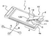
図1は、本実施形態のPCカードの概略構成(ホルダカバーが開いた状態)を示す斜視図、図2は、同PCカードの概略構成(ホルダカバーが閉じた状態)を示す斜視図である。図3は、本実施形態のチップホルダの概略構成を示す斜視図である。 FIG. 1 is a perspective view showing a schematic configuration of the PC card according to the present embodiment (a state where the holder cover is opened), and FIG. 2 is a perspective view showing a schematic configuration of the PC card (a state where the holder cover is closed). . FIG. 3 is a perspective view showing a schematic configuration of the chip holder of the present embodiment.
図1又は図2に示すように、本実施形態(第1実施形態)のPCカード1は、裏面に接続端子を有するSIMカード(チップカード)2を装着することにより、PCの機能を拡張し、無線通信用の送受信端末として用いられるものである。PCカード1は、樹脂製フレーム枠に金属薄板が重ね合わせて形成された薄型ケース状のカード体である。 As shown in FIG. 1 or FIG. 2, the
PCカード1の一方の端面には、PCのカードバス(32ビット)と電気的接続するカード端子(端子部)3が形成されている。このカード端子3は、PCカード1の内部に配置されたプリント基板(図示しない)と電気的に接続されている。 On one end face of the
PCカード1の他方側には、使用者がPCカード1を着脱する際に把持するカード把持部(他端部)4が形成されている。 On the other side of the
ここで、本実施形態の場合、PCカード1が挿入方向Aに装着された状態で、カード把持部4の端面4aは、PCスロットの端面と同一となり、基準端面となる。 Here, in the case of the present embodiment, in a state where the
カード把持部4には、チップホルダ10が設けられている。カード把持部4の占める領域は、この端面4aを含む領域であれば限定されず、チップホルダ10の大きさ及び配置によって定められる。チップホルダ10は、SIMカード2を接続保持し、SIMカード2に記録されている識別情報をPCカード1に伝達するものである。以下、このようなチップホルダ10の構成を具体的に述べる。 The
図3に示すように、チップホルダ10は、ホルダベース11と、ホルダカバー12とからなる。ホルダベース11は、薄型ケース状に形成され、SIMカード2を収容するようになっている。ホルダカバー12は、ホルダベース11と同じ大きさで、両側部に保持フック部12aを有する矩形状に形成され、SIMカード2の裏面を露出してこの両側を保持するようになっている。 As shown in FIG. 3, the
ホルダベース11の後端部分には、一対の支軸11aが固定され、ホルダカバー12の後端部分には、一対の長孔12bが形成されている。ホルダカバー12は、長孔12bに嵌合した支軸11aを中心に、回転移動すると共に、支軸11aに対し接近する軸向心方向C+又は離間する軸遠心方向C−について所定範囲で直進移動するようになっている。ホルダカバー12は、ホルダベース11との間に取り付けられた板バネ(図示しない)により、軸遠心方向C−に付勢されている。 A pair of
ホルダカバー12の先端部分には、一対の係合フック部12cが形成され、ホルダベース11の先端部分には、一対の係止突部11bが形成されている。ホルダカバー12は、この回転移動及び直進移動を伴った、係合フック部12cと係止突部11bとの位置関係により、ホルダベース11と係合又は係合解除するようになっている。 A pair of
図1に示すように、このようなチップホルダ10に対し、カード把持部4には、チップホルダ10をぴったり収めるような凹部が形成され、この凹部にホルダベース11が固着されている。ホルダカバー12は、この回転の軸線方向DがPCカード1の挿入方向Aと直交し、スロット外側A−で開閉するように配置されている。 As shown in FIG. 1, with respect to such a
また、ホルダカバー12が閉じられた場合、ホルダカバー12の上面がPCカード1の上面と同一面上になり、ホルダカバー12の先端縁が、カード把持部4の端面4aからはみ出ないように設定されている。 In addition, when the
そして、PCカード1がPCスロット内に装着された場合、カード把持部4の端面4aは、PCスロットの側面と同一面上に位置するため、ホルダカバー12の先端縁がPCスロットからはみ出ずにこの口元の内面と対向するようになっている。 When the
ホルダベース11には、バネ性端子(図示しない)が、底上面から突出して配置され、PCカード1のプリント基板と電気的に接続されている。このようなバネ性端子は、ホルダカバー12が閉じられた場合において、SIMカード2を、ホルダカバー12の裏面に対し弾性的に押し付けてプリント基板との恒常的な電気的接続を保持する機能と、ホルダカバー12の係合が解除された場合において、ホルダカバー12を開く方向に付勢する機能とを有している。 A spring terminal (not shown) is disposed on the
図1又は図3に示すように、ホルダカバー12の裏面には、位置決め突部12dが形成されている。この位置決め突部12dは、ホルダカバー12の裏面に沿ってスライドしたSIMカード2を係止し、バネ性端子に対して電気的接続の位置を定める機能を有する。 As shown in FIG. 1 or 3, a
次に、チップホルダの使用態様又は作用を説明する。 Next, the usage mode or operation of the chip holder will be described.
図1又は図3に示すように、SIMカード2をPCカード1に装着する場合、SIMカード2を、ホルダカバー12に沿って差し込んだ後、スライドさせて位置決め突部12dに突き当てる。その後、ホルダカバー12を軸向心方向C+に押し込んでから閉じると、この付勢力により、ホルダカバー12は、軸遠心方向C−に直進し、係合フック部12cでホルダベース11の係止突部11bと係合する。 As shown in FIG. 1 or FIG. 3, when the
このようにホルダカバー12が閉じられた状態では、ホルダカバー12に対し軸遠心方向C−に働く付勢力により、係合フック部12cが係止突部11bに押し付けられるため、ホルダカバー12は多少の振動を受けても開かない。また、SIMカード2に働くバネ性端子の弾性力により、バネ性端子がSIMカード2と共にホルダカバー12の裏面に押し付けられるため、SIMカード2はバネ性端子に押し付けられた状態でこれと電気的接続する。 When the
その後、図2に示すように、このようなPCカード1を挿入方向Aに向けてPCスロットに差しこむ。そして、PCカード1がPCスロット内に装着された状態では、ホルダカバー12の先端縁がPCスロットの口元の内面と対向し、かつ、ホルダカバー12の開閉側がスロット外側A−に設定されているため、仮にホルダカバー12の係合状態が解除されたとしても、PCスロット内でホルダカバー12が開かず、PCカード1を抜き出す場合でも、ホルダカバー12がPCスロットの上面に引っ掛かることはない。 Thereafter, as shown in FIG. 2, the
また、PCカード1がPCスロット内に装着された状態では、ホルダカバー12の先端縁がPCスロットからはみ出ていないため、PCカード1の通信中に使用者が誤ってSIMカード2を抜き出すことができない。SIMカード2を取り外す場合には、PCカード1をPCスロットから抜き出した後、ホルダカバー12を、軸向心方向C+に押し込んでその係合状態を解除させてから開く。 In addition, when the
以上述べたように、本実施形態によれば、PCカード1に切り欠きを形成せずにカード把持部4にチップホルダ10を設け、このホルダカバー12の開閉側をスロット外側A−に設定し、かつ、PCカード1がPCに装着された状態でホルダカバー12の先端縁をPCスロットの口元の内面と対向させるようにしたため、ホルダカバー12の係合が解除されても、PCスロット内でホルダカバー12が開くのを防ぐことができる。その結果、捩れや擦過による回路基板等の破壊を防いで信頼性を向上させることができ、また、チップホルダ10が抜けなくなるという事態を防いで操作性を向上させることができる。 As described above, according to the present embodiment, the
特に、本実施形態の場合、以下の点で信頼性及び操作性をさらに向上させることができる。 In particular, in the case of this embodiment, reliability and operability can be further improved in the following points.
(1)ホルダカバー12が閉じられた状態で、この先端縁がPCスロットからはみ出ないようにしたため、PCカード1の通信中に使用者が誤ってSIMカード2を抜き出す事態を防ぐことができる。(1) Since the leading edge is prevented from protruding from the PC slot when the
(2)バネ性端子の弾性を利用してこれをSIMカード2に押し付けると共に、ホルダカバー12の位置決め突部12dにより、SIMカード2とバネ性端子との接続位置を安定させ、SIMカード2とプリント基板との導通信頼性を確保できる。(2) The elasticity of the spring terminal is used to press the
(3)ホルダカバー12について、支軸11a回りの回転移動に、支軸11aに対して軸向心方向C+又は軸遠心方向C−の直進移動を付勢力をもって加えたため、簡素な構成でありながらイジェクト機構と同様な操作性を得ることができる。(3) About the
次に、本発明のPCカードの好ましい他の一実施形態(第2実施形態)を図4及び図5を参照して説明する。 Next, another preferred embodiment (second embodiment) of the PC card of the present invention will be described with reference to FIGS.
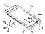
図4は、第2実施形態のPCカードの概略構成(ホルダカバーが開いた状態)を示す斜視図、図5は、同PCカードの概略構成(ホルダカバーが閉じた状態)を示す斜視図である。 FIG. 4 is a perspective view showing a schematic configuration of the PC card according to the second embodiment (a state where the holder cover is opened), and FIG. 5 is a perspective view showing a schematic configuration of the PC card (a state where the holder cover is closed). is there.
図4又は図5に示すように、本実施形態(第2実施形態)のPCカード1Aは、主に、チップホルダ10AのPCカード1Aにおける配置が上記第1実施形態と異なっている。以下、この点について詳述し、その他の構成等については、上記第1実施形態と同符号を付してその説明を省略する。 As shown in FIG. 4 or 5, the
本実施形態のPCカード1Aは、上記第1実施形態とほぼ同様の構成であり、ホルダカバー12は、この回転の軸線方向DがPCカード1Aの挿入方向Aと平行になるように配置され、PC手前側B+が開くようになっている。 The
また、ホルダカバー12は、スロット外側A−の側端縁が、カード把持部4の端面4aからはみ出ないように配置されている。ホルダカバー12の先端部には、摘み部12eが形成されている。この摘み部12eは、スロット外側A−に先端縁の稜線に沿って延び、ホルダカバー12が閉じられた場合にカード把持部4の端面4aと同一面上になるようになっている。これに対応して、カード把持部4の凹部において外壁をなす外壁部4bの稜線には、係合溝4cが、摘み部12eと嵌合するように形成されている。 Further, the
本実施形態の場合、ホルダカバー12がPC手前側B+で開閉するため、使用者がPCカード1AをPCスロットに挿入・抜き出しする際、PCカード1Aを挿入方向Aに向けた状態のままその姿勢を変えずに、ホルダカバー12を開閉したり、SIMカード2の抜き差しをすることができ、このような操作性の点で上記第1実施形態より有利である。 In the case of the present embodiment, the
なお、本実施形態の場合、ホルダカバー12の側端縁のうち、摘み部12eのみをカード把持部4の端面4a上に配置するようにして、開閉する際の操作性を確保すると共に、PCカード1Aの側面に切り欠きを形成せずにこの強度を確保している。 In the case of this embodiment, among the side edges of the
PCカード1Aのその他の構成及び作用効果は、上記第1実施形態と同様である。 Other configurations and operational effects of the
次に、本発明のPCカードの好ましい他の一実施形態(第3実施形態)を図6を参照して説明する。 Next, another preferred embodiment (third embodiment) of the PC card of the present invention will be described with reference to FIG.
図6は、第3実施形態のPCカードの概略構成(ホルダカバーが開いた状態)を示す斜視図である。 FIG. 6 is a perspective view illustrating a schematic configuration of the PC card according to the third embodiment (a state where the holder cover is opened).
図6に示すように、本実施形態(第3実施形態)のPCカード1Bは、主に、カード端子3と反対側の他端に拡張部40が形成されている点と、チップホルダ10のPCカード1Bにおける配置が上記第1実施形態と異なっている。以下、この点について詳述し、その他の構成等については、上記第1実施形態と同符号を付してその説明を省略する。 As shown in FIG. 6, the
本実施形態のカード把持部4Aは、上記第1、第2実施形態におけるカード把持部4の端面4aに拡張部40が形成されたものである。この拡張部40は、上記カード把持部4の端面4aからスロット外側A−及び上方側に張り出しており、この内部にアンテナや外部接続端子等が設けられている。拡張部40は、PCカード1BがPCスロット内に装着された場合、PCスロットからはみ出て配置されるようになっている。 The
本実施形態では、上記第1、第2実施形態におけるカード把持部4に相当する部分と、拡張部40との境界面が、PCスロットの端面と同一となり基準端面となる。そして、PCカード1BがPCスロットに装着された状態で、拡張部40は、その内側面が、PCスロットの側面に対し、使用者の指が挿入できない程度の隙間をおいて対向配置されるようになっている。 In the present embodiment, the boundary surface between the portion corresponding to the
本実施形態のチップホルダ10は、拡張部40と近接する領域に配設され、ホルダカバー12の先端縁が、PCに装着された状態で、PCスロットの端面からはみ出て拡張部40の内側面と当接しないように配置されている。すなわち、ホルダカバー12の先端部は、拡張部40とPCスロットとの隙間で露出しているが、PCカード1BがPCスロットから抜き出されない限り、使用者の手に触れられないようになっている。 The
本実施形態の場合、ホルダカバー12の先端部が、使用者の手に触れられないように露出しているため、ホルダカバー12を透明にすれば、PCカード1Bの通信中にSIMカード2の有無を確認でき、このような操作性の点で、上記第1、第2実施形態より有利である。 In the case of the present embodiment, since the tip of the
PCカード1Cのその他の構成及び作用効果は、上記第1実施形態と同様である。 Other configurations and operational effects of the
次に、本発明のPCカードの好ましい他の一実施形態(第4実施形態)を図7を参照して説明する。 Next, another preferred embodiment (fourth embodiment) of the PC card of the present invention will be described with reference to FIG.
図7は、第4実施形態のPCカードの概略構成(ホルダカバーが開いた状態)を示す斜視図である。 FIG. 7 is a perspective view illustrating a schematic configuration of the PC card according to the fourth embodiment (a state where the holder cover is opened).
図7に示すように、本実施形態(第4実施形態)のPCカード1Cは、このカード把持部4Aの構成について上記第3実施形態と同様であり、チップホルダ10AのPCカード1Cにおける配置が上記第2実施形態と若干異なっている。以下、この点について詳述し、その他の構成等については、上記第1実施形態と同符号を付してその説明を省略する。 As shown in FIG. 7, the
本実施形態のチップホルダ10Aは、ホルダカバー12の側端縁が、PCに装着された状態で、PCスロットの端面からはみ出て拡張部40の内側面と当接しないように配置されている。すなわち、ホルダカバー12の側端縁は、拡張部40とPCスロットとの隙間で露出しているが、PCカード1CがPCスロットから抜き出されない限り、使用者の手に触れられないようになっている。 The
PCカード1Cのその他の構成及び作用効果は、上記第2、第3実施形態と同様である。 Other configurations and operational effects of the
2 SIMカード(チップカード)
3 カード端子部(端子部)
4、4A カード把持部(他端部)
40 拡張部
10、10A チップホルダ
11 ホルダベース
12 ホルダカバー
A 挿入方向
D 軸線方向2 SIM card (chip card)
3 Card terminal part (terminal part)
4, 4A Card grip (other end)
40
Claims (4)
Translated fromJapanese前記チップホルダは、前記端子部と反対側の他端部を含む領域に固着されたホルダベースと、前記端子部以外の側で開閉するように該ホルダベースに回転支持され且つ閉じた状態で該ホルダベースと係合するホルダカバーとからなり、
前記ホルダカバーの先端縁が、前記カード体が情報機器のスロット内に装着された場合に、該情報機器のスロットの側面と同一面上に位置するように構成されていることを特徴とするPCカード。A card body having a terminal portion formed at one end thereof, and a chip holder that holds the chip card and is electrically connected to the card body, and the card body is mounted in the slot of the information device. In a PC card that is electrically connected to the information device via a unit,
The chip holder has a holder base fixed to a region including the other end on the side opposite to the terminal portion, and is rotatably supported by the holder base so as to open and close on the side other than the terminal portion and in a closed state. It consists of a holder cover that engages with the holder base,
The PC is characterized in that the front endedge of the holder cover is configured to belocated on the same plane as the side surface of the slot of the information device when the card body is mounted in the slot of the information device. card.
前記チップホルダは、前記端子部と反対側の他端部を含む領域に固着されたホルダベースと、前記端子部以外の側で開閉するように該ホルダベースに回転支持され且つ閉じた状態で該ホルダベースと係合するホルダカバーとからなり、The chip holder has a holder base fixed to a region including the other end on the side opposite to the terminal portion, and is rotatably supported by the holder base so as to open and close on the side other than the terminal portion, and in a closed state. It consists of a holder cover that engages with the holder base,
前記ホルダカバーの側端縁が、前記カード体が情報機器のスロット内に装着された場合に、該情報機器のスロットの側面と同一面上に位置するように構成されていることを特徴とするPCカード。The side edge of the holder cover is configured to be located on the same plane as the side surface of the slot of the information device when the card body is mounted in the slot of the information device. PC card.
前記チップホルダは、前記拡張部と近接する領域に固着されたホルダベースと、前記端子部以外の側で開閉するように該ホルダベースに回転支持され且つ閉じた状態で該ホルダベースと係合するホルダカバーとからなり、The chip holder is engaged with the holder base in a closed state while being rotatably supported by the holder base so as to be opened and closed on a side other than the terminal portion, and a holder base fixed to a region close to the extension portion. Consisting of a holder cover,
前記ホルダカバーの先端縁が、前記カード体が情報機器のスロット内に装着された場合に、該情報機器のスロットの端面からはみ出て前記拡張部と当接しないように配置されていることを特徴とするPCカード。A tip edge of the holder cover is arranged so as not to protrude from an end surface of the slot of the information device and contact the extension portion when the card body is mounted in the slot of the information device. PC card.
前記チップホルダは、前記拡張部と近接する領域に固着されたホルダベースと、前記端子部以外の側で開閉するように該ホルダベースに回転支持され且つ閉じた状態で該ホルダベースと係合するホルダカバーとからなり、The chip holder is engaged with the holder base in a closed state while being rotatably supported by the holder base so as to be opened and closed on a side other than the terminal portion, and a holder base fixed to a region close to the extension portion. Consisting of a holder cover,
前記ホルダカバーの側端縁が、前記カード体が情報機器のスロット内に装着された場合に、該情報機器のスロットの端面からはみ出て前記拡張部と当接しないように配置されていることを特徴とするPCカード。The side edge of the holder cover is arranged so as not to protrude from the end face of the slot of the information device and contact the extension when the card body is mounted in the slot of the information device. Characteristic PC card.
Priority Applications (1)
| Application Number | Priority Date | Filing Date | Title |
|---|---|---|---|
| JP2004205263AJP4707339B2 (en) | 2004-07-12 | 2004-07-12 | PC card |
Applications Claiming Priority (1)
| Application Number | Priority Date | Filing Date | Title |
|---|---|---|---|
| JP2004205263AJP4707339B2 (en) | 2004-07-12 | 2004-07-12 | PC card |
Publications (2)
| Publication Number | Publication Date |
|---|---|
| JP2006031126A JP2006031126A (en) | 2006-02-02 |
| JP4707339B2true JP4707339B2 (en) | 2011-06-22 |
Family
ID=35897438
Family Applications (1)
| Application Number | Title | Priority Date | Filing Date |
|---|---|---|---|
| JP2004205263AExpired - LifetimeJP4707339B2 (en) | 2004-07-12 | 2004-07-12 | PC card |
Country Status (1)
| Country | Link |
|---|---|
| JP (1) | JP4707339B2 (en) |
Family Cites Families (19)
| Publication number | Priority date | Publication date | Assignee | Title |
|---|---|---|---|---|
| JPS6122554Y2 (en)* | 1979-11-02 | 1986-07-07 | ||
| JPS5936381A (en)* | 1982-08-20 | 1984-02-28 | Matsushita Electric Ind Co Ltd | Cassette adaptor |
| JPS6228892A (en)* | 1985-07-31 | 1987-02-06 | Toshiba Corp | Ic card holder |
| JPH072430Y2 (en)* | 1987-03-18 | 1995-01-25 | 株式会社イトーキクレビオ | Boxed container |
| JPH01178989U (en)* | 1988-06-06 | 1989-12-21 | ||
| JP3173171B2 (en)* | 1991-12-19 | 2001-06-04 | カシオ計算機株式会社 | Information transfer system |
| JPH06195524A (en)* | 1992-09-14 | 1994-07-15 | Toshiba Corp | Memory card device |
| JPH06180965A (en)* | 1992-12-11 | 1994-06-28 | Victor Co Of Japan Ltd | Cassette adaptor |
| DE29607253U1 (en)* | 1996-04-22 | 1996-07-04 | Stocko Metallwarenfabriken Henkels & Sohn GmbH & Co, 42327 Wuppertal | Combi chip card reader |
| US5752857A (en)* | 1996-05-24 | 1998-05-19 | Itt Corporation | Smart card computer adaptor |
| JP3585336B2 (en)* | 1997-02-24 | 2004-11-04 | 沖電気工業株式会社 | IC card adapter |
| JPH10247369A (en)* | 1997-03-03 | 1998-09-14 | Fuji Photo Film Co Ltd | Adapter for magnetic disk cartridge |
| JP3341713B2 (en)* | 1999-06-10 | 2002-11-05 | 日本電気株式会社 | Portable information card holding mechanism, holding method, and information device |
| JP4339477B2 (en)* | 2000-01-24 | 2009-10-07 | 日本圧着端子製造株式会社 | Adapter for card connection |
| JP2001267031A (en)* | 2000-03-22 | 2001-09-28 | Citizen Watch Co Ltd | Interface device for card type electronic equipment |
| JP2002298092A (en)* | 2001-03-30 | 2002-10-11 | Matsushita Electric Ind Co Ltd | PC card |
| JP2002298099A (en)* | 2001-03-30 | 2002-10-11 | Toshiba Corp | Electronics |
| JP2002343505A (en)* | 2001-05-11 | 2002-11-29 | Kyocera Elco Corp | Card detection switching mechanism for card connector |
| JP2003036934A (en)* | 2001-07-19 | 2003-02-07 | Kel Corp | Card connector |
- 2004
- 2004-07-12JPJP2004205263Apatent/JP4707339B2/ennot_activeExpired - Lifetime
Also Published As
| Publication number | Publication date |
|---|---|
| JP2006031126A (en) | 2006-02-02 |
Similar Documents
| Publication | Publication Date | Title |
|---|---|---|
| US6222726B1 (en) | Portable personal computer with arrangement for connecting an expansion card to a socket therein | |
| US7666017B2 (en) | SIM card securing device | |
| TWI251377B (en) | Connector | |
| JP2000305662A (en) | Adapter for card connection | |
| JP2002280097A (en) | Flash memory card connector, connection structure using the same, and electronic device using the connection structure | |
| EP1089212A2 (en) | A plug-in card for electronic devices | |
| JP4811369B2 (en) | Portable electronic devices | |
| JPS63176193A (en) | Information card | |
| EP3537612B1 (en) | Card socket component and electronic device | |
| JP2008522317A (en) | SIM card holding device | |
| JP2004126877A (en) | Card holding structure | |
| JP5547898B2 (en) | Lid opening / closing device | |
| JP2708011B2 (en) | Portable information equipment | |
| JP4707339B2 (en) | PC card | |
| JP5035347B2 (en) | Electronics | |
| CN108540155B (en) | Card insertion device and electronic equipment | |
| JP2006120476A (en) | Electronic card connector | |
| JP4698185B2 (en) | Information equipment card | |
| JP4646579B2 (en) | Information equipment terminal | |
| JP2006114300A (en) | Small electronic equipment | |
| JP5022160B2 (en) | Tray-type card connector | |
| JP4535944B2 (en) | Card connector | |
| JP4662884B2 (en) | Card storage structure and electronic device | |
| JP5455861B2 (en) | Information equipment terminal | |
| JP5202276B2 (en) | Card mounting device |
Legal Events
| Date | Code | Title | Description |
|---|---|---|---|
| A621 | Written request for application examination | Free format text:JAPANESE INTERMEDIATE CODE: A621 Effective date:20070618 | |
| A977 | Report on retrieval | Free format text:JAPANESE INTERMEDIATE CODE: A971007 Effective date:20100629 | |
| A131 | Notification of reasons for refusal | Free format text:JAPANESE INTERMEDIATE CODE: A131 Effective date:20100713 | |
| A521 | Request for written amendment filed | Free format text:JAPANESE INTERMEDIATE CODE: A523 Effective date:20100913 | |
| A01 | Written decision to grant a patent or to grant a registration (utility model) | Free format text:JAPANESE INTERMEDIATE CODE: A01 Effective date:20110215 | |
| A61 | First payment of annual fees (during grant procedure) | Free format text:JAPANESE INTERMEDIATE CODE: A61 Effective date:20110315 |