JP4707249B2 - Component position detection method and apparatus - Google Patents
Component position detection method and apparatusDownload PDFInfo
- Publication number
- JP4707249B2 JP4707249B2JP2001091593AJP2001091593AJP4707249B2JP 4707249 B2JP4707249 B2JP 4707249B2JP 2001091593 AJP2001091593 AJP 2001091593AJP 2001091593 AJP2001091593 AJP 2001091593AJP 4707249 B2JP4707249 B2JP 4707249B2
- Authority
- JP
- Japan
- Prior art keywords
- component
- straight line
- line
- inclination
- detected
- Prior art date
- Legal status (The legal status is an assumption and is not a legal conclusion. Google has not performed a legal analysis and makes no representation as to the accuracy of the status listed.)
- Expired - Lifetime
Links
Images


Landscapes
- Length Measuring Devices By Optical Means (AREA)
- Image Processing (AREA)
- Supply And Installment Of Electrical Components (AREA)
- Image Analysis (AREA)
Description
Translated fromJapanese【0001】
【発明の属する技術分野】
本発明は、部品位置検出方法及び装置、更に詳細には、撮像された電子部品の画像を処理して部品位置を検出する方法及び装置に関する。
【0002】
【従来の技術】
従来、実装機では、フィーダーから供給される電子部品を吸着ノズルで吸着し、吸着ノズルを回路基板上の所定位置に移動させて電子部品を基板に搭載している。この場合、電子部品は、必ずしも正しい姿勢で吸着されるわけではないので、電子部品を回路基板に搭載する際、実装直前に画像認識部において部品の画像データをCCDカメラなどの撮像装置などで取得し画像処理を行って、吸着中心と部品中心のずれ、並びに吸着傾きを検出して部品搭載の位置決めを行い、精度よく電子部品を実装している。
【0003】
この位置決めを効率的に行なうために、従来の実装機では、電子部品を電極の特徴とその特徴の定形的な配置パターンで分類し、それぞれの定型的な情報を前提とした分類別の個別処理で、部品に応じた最適な位置決めを行なっている。
【0004】
また、部品の外形特徴を用いるものとしては、部品が矩形であることを前提とし、4辺を検出し4コーナーの座標を求め、部品中心、傾きを算出して位置決めを行なっている。
【0005】
【発明が解決しようとする課題】
しかしながら、電極を持たない部品、電極の精度が良くない部品では、従来の電極の特徴とその特徴の定形的な配置パターンに基づいて位置決めを行なう方式では対応できず、また、4辺、もしくは4コーナーによる位置決め方式では、部品の形状が四角形に限定されてしまう、という問題があり、電子部品の種類によって位置決め精度が異なったり、あるいは位置決めが困難になる、という問題があった。
【0006】
従って、本発明は、このような問題点を解決するためになされたもので、電子部品の種類に制限を受けることがなく、高精度の位置決めが可能になる部品位置検出方法及び装置を提供することをその課題とする。
【0009】
【課題を解決するための手段】
上記課題を解決するために、本発明は、撮像された部品の画像を処理して部品位置を検出する方法及び装置において、
撮像された部品の外形輪郭線から一つの直線部を検出する工程(手段)と、
前記検出された一つの直線部を用いて、前記部品と外接し、かつ、該直線部と直交する少なくとも一つの外接線を検出する工程(手段)と、
前記検出された一つの直線部から部品傾きを算出する工程(手段)と、
前記一つの直線部と前記外接線との少なくとも1つの交点及び部品寸法データに基づいて部品中心を算出する工程(手段)と、
を備える構成を採用している。
【0010】
本発明は、部品外形輪郭線上に少なくとも1箇所の直線部分があれば、それをもとに位置決めを行うものである。その場合、その検出された一つの直線部から部品傾きを算出する。また、検出された一つの直線部を用いて部品と外接する少なくとも一つの外接線を検出し、前記一つの直線部と前記外接線との少なくとも1つの交点、及び部品の高さ(縦)寸法、部品の幅(横)寸法などの部品寸法データを参照して部品中心を算出する。
【0011】
このように、本発明では、例えば、タンタルコンデンサ等、部品外形の一部が丸みを帯びているような電子部品においても、その中心位置および傾きを検出し、搭載することができる。
【0012】
【発明の実施の形態】
以下、図面に示す実施の形態に基づいて本発明を詳細に説明する。
【0013】
[全体の構成]
図1には、本発明の一実施形態に係わる部品位置検出装置が図示されている。同図において符号11で示すものは電子部品(以下、単に部品という)で、この部品11は部品供給部(不図示)から供給され、吸着ノズル12により吸着される。部品の吸着姿勢を認識するために、部品11は4面にそれぞれ多数の照明ランプ13a、13b、13cを備えた照明装置13により照明され、撮影レンズ14を備えた撮像カメラ(CCDカメラなど)15で撮像され、画像入力が行なわれる。
【0014】
撮像カメラ15で撮像された部品の画像は、画像処理装置17のCPU18の制御の元にA/Dコンバータ19を介してデジタル信号に変換され、画像メモリ20に格納される。また画像処理装置17には、後述するように部品の縦横寸法などの外形サイズ、エレメント、エレメントグループなど部品データを格納した部品データ格納メモリ23が設けられる。CPU18は、メモリ23に格納された部品データに基づき画像メモリ20に取り込まれた部品の画像を認識し、撮像部品の中心と傾きなどを演算する。また、画像処理装置17には、テンプレートメモリ21が設けられ、このテンプレートメモリには、部品外形サイズ、リードの本数、リード長さ、リードピッチ、リード幅情報などの部品データに基づいて形成されたテンプレートが格納され、テンプレートマッチングにより部品の概略位置を検出できるようになっている。さらに、画像処理装置17には、モニタ22が接続されており、入力画像あるいは処理画像を表示できるようになっている。
【0015】
図1に図示した部品位置検出装置は、実装機(不図示)に設けられ、吸着ノズル12に吸着された部品11を撮像カメラ15で撮像し、その画像を画像処理装置17で処理して撮像された部品画像の位置(部品中心と部品傾き)を検出する。
【0016】
以下に、このように構成された部品位置検出装置で画像処理装置17において行なわれる部品位置検出処理の流れを図2を参照して説明する。
【0017】
[部品データの格納(ステップS3)]
電源投入後、画像処理装置17は、実装機のメイン制御装置(不図示)よりのコマンド待ちとなり、実装機からコマンドを受信すると(ステップS1)、これを解析して実行する(ステップS2)。「認識条件設定」で、画像処理装置17は、実装機のメイン制御装置から部品データを受信し、これを部品データ格納メモリ23に格納する(ステップS3)。
【0018】
本発明では、部品は次の2通りの表現方法で記述される。
【0019】
その一つは、汎用部品の位置検出のために、考案されたデータ表現であって、属性を設定した電極(リード、ボール等)や位置決め可能な特徴がある部分(辺、コーナー、マーク等)を最小構成単位要素(以下エレメントと記述)として扱い、このエレメントとその配置情報などを属性としたエレメント構成要素(以下エレメントグループと記述)を設定し、また、このエレメントグループの集合と部品の縦(高さ)、横(幅)寸法などの部品としての属性情報から1個の部品を記述する方法である。
【0020】
また、簡易的な部品データの表現方法として、部品の縦(高さ)、横(幅)寸法と、4方向の中で直線形状である辺、もしくはコーナーを指定し、直線が存在する方向と、直線と部品中心との位置関係を記述する方法がある。
【0021】
以上のいずれかの表現方法、あるいは両表現方法を用いて記述された部品データが画像処理装置17に受信され、部品ID(部品識別番号)ごとに部品データ格納メモリ23に格納される。本発明では、具体的には、4辺、4コーナー、3辺、3コーナー、2辺、2コーナー、1辺の外形特徴を持つ部品の位置決めが可能であるので、部品がこれらの外形特徴をもつかどうかの情報、これらの外形特徴がある場合には、部品のどの部分に直線部があるのか、また直線部と中心との位置関係などの位置情報も各部品データの属性として格納する。これらの情報と実際に検出した画像上の外形特徴位置から部品の位置決めが可能になる。
【0022】
[認識実行]
実装機の吸着ノズル12が部品供給部(不図示)より部品11を吸着し、吸着ノズル12が撮像カメラ15の位置に移動したとき、実装機のメイン制御装置は照明装置13を点灯させ、画像処理装置17へ位置検出の実行を指示し、認識実行となる。
【0023】
認識実行指令を受信すると、画像処理装置17は、吸着ノズル12の軸中心が撮像カメラ15の撮影軸(撮像画面の中心)と一致する位置において、部品11を撮像カメラ15で撮像し、画像データをA/Dコンバータ19を経由し、画像メモリ20に格納する。画像データの格納が終了すると、CPU18は部品データ格納メモリ23に保持している部品データを参照し、部品IDを元に吸着されている部品の部品データを取り出す(ステップS4)。続いて、取り出された部品データから上記外形特徴(パターン)があるかどうかを判断し(ステップS5)、外形特徴があると判断された場合は、部品のどの部分に直線部があるのか、また直線部と中心との位置関係などの位置情報も読み出し、それぞれの位置決め処理に分岐する。
【0024】
画像処理装置におけるそれぞれの位置検出処理の基本的な流れは、部品外形輪郭線からの直線部の検出(直線ないし辺の検出)又はコーナーの検出(ステップS6)、部品の傾き算出(ステップS7)、部品の中心算出(ステップS8)となり、直線検出、コーナー検出については、各外形特徴に対してほぼ共通であるので一括して説明し、傾き算出、中心算出は、外形特徴の種類(コーナー、辺)、数、位置によって、異なるので、以下に、外形特徴別に説明する。
【0025】
[直線の検出(ステップS6)]
直線検出に対しては、
Sobel+ハフ変換+最小自乗法による直線検出方式を適用する。すなわち、エッジ点列(辺の点列)を取得し、直線抽出(ハフ変換+最小自乗法)する。
【0026】
(1)エッジ点列の取得
まず、エッジ点列を取得するために、部品寸法をもとにウインドウを設定し、サーチ範囲を絞り込む。上述したように、部品データの属性として、部品のどの部分に直線部があるのか、また直線部と中心との位置関係などの位置情報が格納されているので、図3(A)に示したように、撮像画面32内の撮像部品(画像)30の直線部(辺)を含む領域にサーチウインドウ31が設定される。このウインドウが設定されたら、基準軸より基準軸に垂直な方向に延びる所定間隔の走査線33を目標辺に対して投射し、部品外形輪郭線の辺を示す点列(エッジ点列)33aの座標とエッジ方向、強さを求める。
【0027】
上記走査線の間隔は、部品寸法により設定する。走査線の間隔は、短いほど精度は上がるが処理時間は大きくなるので、サンプリング点数は最大64点とする。エッジ(辺)であるかどうかの判定は、濃度値が指定されたしきい値を超えるかどうかで行なう。直線抽出にハフ変換を使うのですべてのエッジが正しくなくてもかまわない。このときエッジの方向を求めておくと、ハフ変換での投票処理を軽減することができる。エッジの方向(傾き)は、例えば、Sobelオペレータを用いて、次のようにして求められる。
【0028】
まず、部品画像のピクセルP(x,y)において、x方向、y方向の微分値は、
エッジ強度(Power)は、
Power = sqrt(f'x*f'x + f'y*f'y)
エッジ方向(θ)は、
tanθ = f'y/f'x
のように求められる。
【0029】
またベクトルの内積、外積を利用し、
cosθ = f'x / power
sinθ = −f'y / power
と表わすこともできる。すなわち、ρ−θ空間での軌跡を求める際、三角関数演算の必要がない。
【0030】
辺に傾きがある場合には、先の点列には隣接辺のデータも含まれる。しかし、傾きが小さいならばこの点列の大部分の点が検出したい辺の点列である。
【0031】
(2)直線抽出(ハフ変換+最小自乗法)
上記のようにして、エッジ点列が求められたら、この点列についてハフ変換を用い、最も多くの点がのる直線を求め、この直線に投票した点列を用い、最小自乗法で直線式を求め直して直線を抽出する。この処理を以下に説明する。
【0032】
ハフ変換には、図形空間上の直線がとぎれとぎれだったり、ノイズが多く含まれている場合にも投票結果にあまり影響なく、直線を抽出できるという利点がある。しかし、精度よく求めることは難しいので、それをカバーするため、最小自乗法と組み合わせた実装を考える。
【0033】
まず、直線ρ=xcosθ+ysinθのθを決定する。(1)の処理で、各点のエッジ方向θiと座標Pi(xi、yi)が求まっているので、その点を通る直線式(直線ρ=xcosθ+ysinθ)を一意に決めることができる。理論的には、このρ、θで2次元配列に投票し、最大投票数を示すρ−θを選択すればよいのであるが、θの精度が良くないので明確なピークを得ることができない。そこでまずθについてのみ、ある程度変動させて投票を行ない正解値に近いθを得る。
【0034】
また、(1)で得られたエッジ点列は部品が傾いている場合、雑音+直線1(求めたい辺)+直線2(求めたい辺に垂直な辺)で構成されている。その場合、θの変動範囲を基準軸に対して±45°以内とするなら、θをチェックすることで求めたくない辺のデータをあらかじめ分離できるので、これらの点については投票処理を行なわないようにする。
【0035】
続いて、上述のようにして求めたθと各点の座標Pi(xi,yi)より、
直線ρ=xcosθ+ysin
のρを決定し、ρ、θを微量に変動させ投票を行なう。
【0036】
上記ハフ変換で求める直線の精度は投票空間の解像度に依存する。精度を上げるために解像度を上げると作業メモリ量は増大し、またピークも出にくくなり、逆に解像度を下げるとピークは出るが精度は落ちる。そこで、ハフ変換はエッジ点列の分類手段と考え、ハフ変換の結果を最終出力にするのではなく、最大スコアの直線に投票した点列のみで最小自乗法により直線式を再計算する。これにより、ハフ変換の投票空間は粗いものでも、精度よく直線を抽出することができる。
【0037】
[コーナー検出(ステップS6)]
コーナーは、エッジ点列を検出したときと同一のサーチウインドウ31内で縦、横方向に走査することにより縦、横方向の直線を検出し、その交点をコーナーの検出点とする。しかしながら、コーナーは辺に比べ局所的な特徴であるので、吸着ずれや付近の類似の特徴の存在を考慮したとき、単純なサーチウインドウの設定では対応できない。従って、本発明では、コーナー検出用にウインドウを調整し、またコーナーの妥当性チェックを行なう。これを次に説明する。
【0038】
(1)コーナー検出のためのウインドウ調整方法
部品データが簡易表現されていて、外形中心と部品中心が一致する場合には、
(a)画像上での部品外接線を求め、仮の中心を求める。
【0039】
(b)(a)で求めた仮の中心と部品の寸法より概略のコーナー位置を算出する。
【0040】
(c)部品最大変動領域に対してウインドウを設定し、コーナー外側に対応する角から斜め45°の走査線で走査し、部品端を検出する。
【0041】
(d)(c)で検出した点を基準にコーナー検出用のウインドウを設定する。
【0042】
このようにして設定されたコーナー検出用のウインドウにおいて、上記直線検出を用いて、コーナーを構成する2直線を検出し、その交点を求め、コーナーを検出する。
【0043】
一方、部品データが、エレメント表現で記述され、外形中心と部品中心が一致しない場合には、ウインドウの位置、サイズを調整してのリトライにより吸着ずれ、回転ずれに対応する。
【0044】
また、コーナーの誤検出を防ぐために、以下のコーナー妥当性チェックを組み合わせる。
【0045】
(a)部品データの中心と画像中心が一致しているとして、コーナー位置を算出する。
【0046】
(b)部品の吸着ずれが±1mm、θずれが±3.5°と想定してウインドウをかけ、以降の処理で、コーナーが検出できない場合、ウインドウサイズを調整しリトライし、ウインドウサイズを、小から大の方向に調整する(本実施形態では、ウインドウサイズは3段階で調整している)。
【0047】
(c)ウインドウのコーナー外側に対応する2辺が背景領域にあるかどうかをチェックし、部品内部にかかっている場合には、ウインドウを外側にずらす。例えば、図3(B)に示したように、ウインドウ31aが部品(画像)30に初期設定されている場合、2辺が背景領域にないので、ウインドウを外側にずらし、2辺が部品内部にはいるような調整ウインドウ31bにする。最大変動領域内でこの条件をクリアできない場合は、(b)に戻り、ウインドウサイズを調整限界31cまで調整する。
【0048】
(d)このウインドウの各調整過程で、コーナーを構成する2直線を検出し、その交点を求める。直線が検出できなかった場合、(b)に戻り、ウインドウサイズを変えてリトライする。
【0049】
(e)以下で述べるコーナー妥当性チェックを行い、求めるコーナーであるかどうかをチェックし、コーナー妥当性チェックに引っかかった場合には、(b)に戻り、ウインドウサイズを変えてリトライする。
【0050】
(f)コーナーが複数指定されている場合、コーナー間距離のチェックを行う。
【0051】
(2)コーナー妥当性チェック
このコーナーの妥当性チェックでは、図4(A)に示したように、コーナーとして検出された検出点P1の近傍に部品輪郭30aがあるかどうかをチェックする。これは、図4(B)に示したように、サーチウインドウ41において部品40のコーナーが検出点P1’として検出された場合、P1’の近傍に部品40の輪郭がないので、コーナーの誤検出となる。そこで、このような誤検出を防ぐために、検出点の近傍(R指定値を目安にする)に部品の輪郭があるかどうかでチェックする。これは、例えば、図4(A)に示したように、検出点P1から径R+1mmのところに位置するそれぞれの検査点P2、P2’のところで、エッジが検出された場合には、コーナーの検出点P1の近傍には部品輪郭があり、コーナー検出に妥当性があるとする。
【0052】
また、部品データ上に複数のコーナーエレメントを持つときは、コーナー相互の位置関係(コーナー間距離)をチェックすることでコーナー検出誤りによる誤搭載を防ぐ。この場合、検査点数は、指定順で最大4点までが対象となる(最大6線分の距離をチェックする)。また、検出座標から求まる2点間距離と部品データから求まる2点間距離の差が許容値であるかどうかで、コーナーの妥当性をチェックする。この場合の許容値は±2mmとする。分割認識等で2点間距離がさらに長くなる場合、ピクセルレートの誤差の影響が大きくなるので、距離に合わせて許容値を可変にしている(2点間距離が512ピクセルを越える毎に+2mm拡大)。
【0053】
[コーナー3点による位置決め(ステップS61)]
上述のコーナー検出で、部品にコーナー3点が検出された場合には、この3点から部品の傾きを検出する。すなわち、検出した3点から互いに直角の位置関係にある2線分を求め、垂直線分の垂直二等分線と、水平線分の垂直二等分線の交点を部品中心とし、水平線分の水平軸に対する傾き、垂直線分の垂直軸に対する傾きから求めた傾きを部品傾きとする。
【0054】
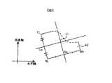
例えば、図5に示したように、部品42に検出されたコーナーがTL、BL、BRであった場合、線分TL−BLの垂直二等分線Lmと、線分BL−BRの垂直二等分線Bmの交点(=TL−BRの中点)Oを部品中心とし、線分BL−BRの水平軸に対する傾き、線分TL−BLの垂直軸に対する傾きの平均値を部品傾きとする。傾きは、平均値だけでなく選択した辺の傾きをもって部品傾きとすることもできる。
【0055】
[コーナー2点による位置決め(ステップS62)]
図6(A)に図示したように、部品43に2コーナーTL、TRが検出された場合には、検出した2点TL、TRを結ぶ線分の中点Tmから、線分に垂直な直線V上で部品内側に部品高さ寸法/2の距離にある点Oを求め、これを部品中心とし、また検出した2点TL、TRを結ぶ線分が水平に近いならば、水平軸に対する傾き、垂直に近いならば垂直軸に対する傾きを部品傾きとする。この精度は部品データの正確さ、ピクセルレートの正確さに関係する。
【0056】
上述した例は、辺の両端にコーナーが検出された場合であるが、図6(B)に図示したように、部品の対角線上にコーナーが検出された場合には、部品44の検出されたコーナーの2点TL、BRから求めた線分TL−BRの傾きと、部品寸法から求まる正姿勢時の対角2コーナーの線分TL’−BR’に対する傾きθを部品傾きとし、検出した2点を結ぶ線分TL−BRの中点Oを部品中心とする。部品傾きの精度は、部品寸法の正確さに関係する。
【0057】
[3辺による位置決め(ステップS63)]
上記検出において、図7に図示したように、部品45に3辺B、R、Lが検出された場合は、直線Bと直線Lの交点BLと、直線Bと直線Rの交点BRの2点を求め、その2点を結ぶ線分の中点Bmから、線分に垂直な直線上で部品内側に部品高さ寸法/2の距離にある点Oを求め、それを部品中心とする。また検出した直線Bの水平軸に対する傾き、直線L、直線Rの垂直軸に対する傾きの平均値を部品傾きとする。傾きは、平均値だけでなく選択した直線B、R、あるいはLの傾きを部品傾きとすることもできる。検出精度は、部品データの精度、ピクセルレートの精度に関係する。
【0058】
[2辺による位置決め(ステップS64)]
また、上記検出において、図8に図示したように、部品46の隣接する2辺B、Lが検出された場合は、直線B、Lの交点BLを求めて基準点とし、この点を始点とし、直線B、Lのそれぞれの半直線上に部品幅/2、部品高さ/2の距離にある点Bm、Lmをとり、この点Bmを通り、直線Bに垂直な直線と、点Lmを通り直線Lに垂直な直線の交点Oを部品中心とする。また、部品傾きは、直線Bの水平軸に対する傾き、直線Lの垂直軸に対する傾きの平均値を部品傾きとする。傾きは、平均値だけでなく選択した直線LあるいはBの傾きを部品傾きとすることも可能である。検出精度は、部品データの精度、ピクセルレートの精度に関係する。
【0059】
[1辺による位置決め(ステップS65、S66、S67)]
上記辺の検出において、検出した一辺を用いて位置検出を行なう場合には、「1辺+重心」、「1辺+外接線」、「平行2辺と外接線」、「片側外接線」、「基準線と4方向外接線」を利用して、部品中心と傾きを求める。「1辺+重心」を利用する場合には、図9(A)に示したように、検出した部品50の辺50aの水平軸ないし垂直軸に対する傾きから部品傾きを求め、指定領域51における部品50の重心Oを算出してこれを部品中心とする。
【0060】
他の方法を利用する場合は、基準線を求め、この基準線に対して垂直な走査線(走査幅は部品幅)で部品を走査し外接直線(外接線)を求めるので、以下に、基準線、外接線を求める方法を説明する。まず、基準線に関しては、図10(A)に図示したように、部品60においてサーチウインドウ31で、辺(直線)60aが検出された場合、この検出された辺60aと一致する線61が基準線となり、図10(B)のように、更に対向する辺60bも検出する場合には、辺60aと60bと一致する直線61a、61bの傾き、切片を平均した直線62を基準線とする。この場合、辺の代わりに2つ以上のコーナーから求めた直線を基準線として利用することもできる。
【0061】
このような基準線が求まると、この基準線に対して垂直な走査線で部品を走査する。この走査起点は、図10(C)に示したように、サーチウインドウ31の枠上にある点60cを定め、この点で辺60aに対して垂直な走査線63を発生させ、この走査線63を外側に順次移動させて部品を走査し外接線を検出する。また、部品データから部品の外部側に位置する走査起点60d、60d’を定め、この点60d、60d’で辺60a、60bに対して垂直な走査線64を発生させ、この走査線64を部品内側に向けて順次移動させて外接線を検出するようにしてもよい。
【0062】
外接線であるかどうかの判定は、走査線の2値化プロジェクション値を判定することで行う。走査線63、64が部品を走査する場合には、部品部分では、例えば「白」となり、また部品なしの部分では、「黒」となるので、走査線の各ドットごとに「1(白)」と「0(黒)」に2値化できる。この走査線上の各ドットごとの「1」の値をプロジェクション値として加算(総計)する。この場合、「1」の値が3以上連続しない場合は、雑音があるので、プロジェクション値として加算しないようにする。このようにプロジェクション値(加算値)が4となった場合に、そのときの走査線を外接線として検出する。この場合、1本の走査線のプロジェクション値判定で即、外接線とせず、さらに走査を行い、連続5本の走査で判定結果がOKであれば、それを外接線として採用する。
【0063】
以上のような走査で、図10(E)に示したような外接線65を求め、検出辺60aの直線との交点65aの座標を求め、これに部品外形寸法から求まる部品中心へのオフセットベクトルを加算し、部品中心を得る。すなわち、外接線65上で交点65aから部品横寸法/2の距離のところで立てた垂線と、検出辺60a上で交点65aから部品縦寸法/2の距離のところで立てた垂線の交点Oを部品中心とする。これが、「1辺+外接線」を利用する方法である。
【0064】
また、「平行2辺と外接線」を利用する場合は、図10(F)に示したように、検出辺60aと60bを用いる場合は、外接線との交点は2点65a、65bであるのでそれぞれの点から図(E)に示した方法で部品中心を求め、その平均を部品中心とする。また、この場合は、2辺60a、60bのそれぞれの傾き角度を比較したり、外接線65と2辺60a、60bとの交点間距離を部品寸法と比較するなどして異部品チェックを行い、誤搭載を防止する。
【0065】
「片側外接線」を利用する場合は、図9(B)に図示したように、部品52の辺52aが検出され、また2つの外接線53、54が検出された場合、いずれか一方の外接線、例えば右側の外接線53のみを利用するもので、辺52aと外接線53の交点53aを求め、辺52aの水平軸ないし垂直軸に対する傾きを部品傾きとし、「1辺+外接線」と同様に、外接線53上で交点53aから部品縦寸法/2の距離のところで立てた垂線と、検出辺52a上で交点53aから部品横寸法/2の距離のところで立てた垂線の交点Oを部品中心とする。
【0066】
また、「基準線と4方向外接線」を利用する場合は、図11に図示したように、部品70で検出された1辺70aと一致する基準線71により部品を走査して4つの外接線を求め、各外接線の交点を結ぶ対角線72の交点Oを部品中心とし、検出辺70aの水平軸ないし垂直軸に対する傾きを部品傾きとする。
【0067】
[部品搭載]
上述したように、吸着ノズルで吸着された部品を撮像し、画像処理により部品中心と部品傾きが検出されたので、部品の吸着姿勢が補正される。吸着傾きは、部品傾きに対応するので、この傾きを補正し、また、吸着中心は、撮像画面32の中心(撮像カメラの撮影軸)にあるので、検出した部品中心と画面中心のX、Y方向の位置ずれをそれぞれ補正して部品を基板に搭載する。
【0068】
なお、上述した実施形態で、辺とコーナーとに分けて説明してきたが、2コーナーからは1辺が算出でき、3コーナーからは直角の関係にある2辺を算出することが可能なので、2コーナーと1辺、あるいは3コーナーと2辺は同様の扱いが可能である。
【0069】
【発明の効果】
以上説明したように、本発明では、電子部品を構成する外形輪郭線の直線部を検出し、直線で構成される特徴位置から部品中心、傾きを求めるので、電極を持たない電子部品でも位置決め可能となる。また、本発明では、電子部品を構成する外形輪郭線に少なくとも1箇所、水平(垂直)線分部分があればよいので、従来手法の外形輪郭が四角形であることという制限を撤廃できる。
【図面の簡単な説明】
【図1】本発明の部品位置検出装置の全体の構成を示す構成図である。
【図2】部品位置検出の流れを示す流れ図である。
【図3】部品の辺を検出する方法を説明した説明図である。
【図4】部品コーナーの検出点の妥当性を調べる状態を説明した説明図である。
【図5】部品の3コーナーから部品中心、部品傾きを求める方法を説明した説明図である。
【図6】部品の2コーナーから部品中心、部品傾きを求める方法を説明した説明図である。
【図7】検出した3辺と部品データから部品中心、部品傾きを求める方法を説明した説明図である。
【図8】検出した2辺と部品データから部品中心、部品傾きを求める方法を説明した説明図である。
【図9】部品の1辺から部品中心、部品傾きを求める方法を説明した説明図である。
【図10】一つの直線部を元に外接線を求め、部品中心、部品傾きを求める方法を説明した説明図である。
【図11】一つの直線部と4方向外接線を用いて部品中心、部品傾きを求める方法を説明した説明図である。
【符号の説明】
11 電子部品
12 吸着ノズル
15 撮像カメラ
17 画像処理装置
20 画像メモリ
23 部品データ格納メモリ[0001]
BACKGROUND OF THE INVENTION
The present invention relates to a component position detection method and apparatus, and more particularly to a method and apparatus for processing a captured electronic component image to detect a component position.
[0002]
[Prior art]
Conventionally, in a mounting machine, an electronic component supplied from a feeder is sucked by a suction nozzle, and the suction nozzle is moved to a predetermined position on a circuit board to mount the electronic component on the substrate. In this case, since the electronic component is not necessarily picked up in the correct posture, when the electronic component is mounted on the circuit board, the image recognition unit acquires image data of the component with an imaging device such as a CCD camera immediately before mounting. Then, the image processing is performed to detect the deviation between the suction center and the component center and the suction inclination, thereby positioning the component and accurately mounting the electronic component.
[0003]
In order to perform this positioning efficiently, conventional mounting machines classify electronic components according to the electrode features and the regular arrangement pattern of the features, and perform individual processing by classification based on the respective typical information. Therefore, the optimum positioning according to the part is performed.
[0004]
In order to use the external feature of the component, assuming that the component is rectangular, the four sides are detected, the coordinates of the four corners are obtained, the component center and the inclination are calculated, and positioning is performed.
[0005]
[Problems to be solved by the invention]
However, parts that do not have electrodes or parts that do not have good electrode accuracy cannot be handled by the conventional positioning method based on the characteristics of the electrodes and the regular arrangement pattern of the characteristics. In the positioning method using the corner, there is a problem that the shape of the part is limited to a quadrangle, and there is a problem that the positioning accuracy differs depending on the type of the electronic part, or the positioning becomes difficult.
[0006]
Accordingly, the present invention has been made to solve such problems, and provides a component position detection method and apparatus that enables highly accurate positioning without being limited by the type of electronic component. That is the issue.
[0009]
[Means for Solving the Problems]
In order to solve the above problems, the present invention relates to a method and apparatus for detecting a component position by processing an image of a captured component.
A step (means) for detecting one straight line portion from the contour outline of the imaged component;
The detectedOneWith straight sectionThe aboveParts and circumscriptionAnd orthogonal to the straight line portionDetecting at least one circumscribing line (means);
The detectedOneA step (means) for calculating the component inclination from the straight line part;
AboveOneStraight section andSaidCircumscribed lineAt least one intersection withAndPartGoodsSizeDayToA step (means) for calculating a component center based on,
Configuration withTheAdopted.
[0010]
In the present invention, if there is at least one straight line portion on the part outline, the positioning is performed based on that. In that case, its detectedOneStraight linePartParts tiltThecalculate.Also,was detectedOneDetect at least one circumscribing line that circumscribes the part using the straight line part,Said oneStraight section andSaidCircumscribed lineAt least one intersection with,as well asParts such as part height (vertical) dimensions and part width (horizontal) dimensionsSizeCalculate the center of the part by referring to the data.
[0011]
As described above, according to the present invention, for example, even in an electronic component such as a tantalum capacitor whose part outer shape is rounded, its center position and inclination can be detected and mounted.
[0012]
DETAILED DESCRIPTION OF THE INVENTION
Hereinafter, the present invention will be described in detail based on embodiments shown in the drawings.
[0013]
[Overall configuration]
FIG. 1 shows a component position detection apparatus according to an embodiment of the present invention. In the figure,
[0014]
The component image captured by the
[0015]
The component position detection apparatus illustrated in FIG. 1 is provided in a mounting machine (not shown), and the
[0016]
Hereinafter, the flow of the component position detection process performed in the image processing device 17 by the component position detection device configured as described above will be described with reference to FIG.
[0017]
[Storage of parts data (step S3)]
After the power is turned on, the image processing device 17 waits for a command from a main control device (not shown) of the mounting machine, and when receiving a command from the mounting machine (step S1), analyzes and executes it (step S2). In “recognition condition setting”, the image processing device 17 receives the component data from the main control device of the mounting machine and stores it in the component data storage memory 23 (step S3).
[0018]
In the present invention, a component is described in the following two ways.
[0019]
One of them is a data expression devised for detecting the position of general-purpose parts, which has electrodes (leads, balls, etc.) with attributes set and features that can be positioned (sides, corners, marks, etc.) Is defined as the minimum component unit element (hereinafter referred to as element), and an element component element (hereinafter referred to as element group) with this element and its layout information as attributes is set. This is a method of describing one part from attribute information as a part such as (height) and lateral (width) dimensions.
[0020]
In addition, as a simple method of expressing component data, specify the vertical (height) and horizontal (width) dimensions of a component, a side or corner that is a straight line shape in four directions, and the direction in which a straight line exists. There is a method for describing the positional relationship between the straight line and the part center.
[0021]
Component data described using any one of the above-described representation methods or both representation methods is received by the image processing device 17 and stored in the component
[0022]
[Recognition execution]
When the suction nozzle 12 of the mounting machine picks up the
[0023]
When receiving the recognition execution command, the image processing device 17 images the
[0024]
The basic flow of each position detection process in the image processing apparatus is as follows: detection of a straight line portion (detection of a straight line or a side) or detection of a corner (step S6) and calculation of the inclination of a component (step S7). The center calculation of the part (step S8), and the straight line detection and the corner detection are almost common to the respective external features, and will be described collectively. The inclination calculation and the center calculation are performed according to the types of external features (corner, Side), the number, and the position.
[0025]
[Detection of straight line (step S6)]
For straight line detection,
A straight line detection method based on Sobel + Hough transform + least square method is applied. That is, an edge point sequence (side point sequence) is acquired, and a straight line is extracted (Hough transform + least square method).
[0026]
(1) Acquisition of edge point sequence
First, in order to acquire the edge point sequence, a window is set based on the component dimensions, and the search range is narrowed down. As described above, as the attribute of the part data, the position information such as which part of the part has the straight line part and the positional relationship between the straight line part and the center is stored. As described above, the
[0027]
The interval between the scanning lines is set according to the component dimensions. The shorter the interval between scanning lines, the higher the accuracy but the longer the processing time. Therefore, the number of sampling points is 64 at maximum. Whether or not an edge (side) is determined is determined by whether or not the density value exceeds a specified threshold value. Since the Hough transform is used for line extraction, all the edges need not be correct. If the edge direction is obtained at this time, the voting process in the Hough transform can be reduced. The direction (inclination) of the edge is obtained as follows using, for example, a Sobel operator.
[0028]
First, in the pixel P (x, y) of the component image, the differential values in the x and y directions are
Edge strength (Power) is
Power = sqrt (f′x * f′x + f′y * f′y)
Edge direction (θ) is
tan θ = f′y / f′x
It is required as follows.
[0029]
Also, using the inner product and outer product of vectors,
cos θ = f′x / power
sin θ = −f′y / power
It can also be expressed as That is, there is no need for trigonometric function calculation when obtaining the locus in the ρ-θ space.
[0030]
When the side has an inclination, the previous point sequence includes data on the adjacent side. However, if the inclination is small, most of the points in this point sequence are the point sequences to be detected.
[0031]
(2) Line extraction (Hough transform + least squares method)
When an edge point sequence is obtained as described above, a straight line carrying the most points is obtained using the Hough transform for this point sequence, and a linear formula is obtained by the least square method using the point sequence voted on this line. To find a straight line. This process will be described below.
[0032]
The Hough transform has an advantage that a straight line can be extracted with little influence on the voting result even when the straight line in the graphic space is broken or contains a lot of noise. However, since it is difficult to obtain with high accuracy, an implementation combined with the method of least squares is considered to cover it.
[0033]
First, θ of the straight line ρ = x cos θ + ysin θ is determined. Since the edge direction θi and the coordinates Pi (xi, yi) of each point are obtained by the process (1), a linear expression (straight line ρ = x cos θ + ysin θ) passing through the point can be uniquely determined. Theoretically, it is only necessary to vote for a two-dimensional array with ρ and θ and select ρ−θ indicating the maximum number of votes. However, since the accuracy of θ is not good, a clear peak cannot be obtained. Therefore, voting is performed by varying the degree of θ only to some extent, and θ close to the correct value is obtained.
[0034]
Further, the edge point sequence obtained in (1) is configured by noise + straight line 1 (side to be obtained) + straight line 2 (side perpendicular to the side to be obtained) when the component is inclined. In that case, if the variation range of θ is within ± 45 ° with respect to the reference axis, the data of the side that is not desired to be obtained can be separated in advance by checking θ, so that voting processing is not performed for these points. To.
[0035]
Subsequently, from θ obtained as described above and the coordinates Pi (xi, yi) of each point,
Straight line ρ = x cos θ + ysin
Ρ is determined, and voting is performed by changing ρ and θ by a small amount.
[0036]
The accuracy of the straight line obtained by the Hough transform depends on the resolution of the voting space. Increasing the resolution to increase the accuracy increases the amount of working memory and makes it difficult for peaks to occur. Conversely, if the resolution is decreased, the peak appears but the accuracy decreases. Therefore, the Hough transform is considered as a means for classifying edge point sequences, and the result of the Hough transform is not used as the final output, but the linear formula is recalculated by the least square method only with the point sequence voted for the straight line of the maximum score. As a result, even if the Hough transform voting space is rough, a straight line can be extracted with high accuracy.
[0037]
[Corner detection (step S6)]
The corner is detected by scanning in the vertical and horizontal directions in the
[0038]
(1) Window adjustment method for corner detection
If the part data is simply expressed and the center of the outline matches the part center,
(A) A part tangent on the image is obtained, and a temporary center is obtained.
[0039]
(B) The approximate corner position is calculated from the temporary center obtained in (a) and the dimensions of the part.
[0040]
(C) A window is set for the component maximum fluctuation region, and scanning is performed with a scanning line obliquely 45 ° from the corner corresponding to the outside of the corner, thereby detecting the end of the component.
[0041]
(D) A corner detection window is set based on the points detected in (c).
[0042]
In the corner detection window set in this manner, the above-described straight line detection is used to detect two straight lines constituting the corner, find an intersection thereof, and detect the corner.
[0043]
On the other hand, if the component data is described in element representation and the center of the outline and the center of the component do not coincide with each other, it corresponds to the adsorption displacement and rotation displacement by retrying the window position and size.
[0044]
In order to prevent corner detection errors, the following corner validity check is combined.
[0045]
(A) The corner position is calculated on the assumption that the center of the part data is coincident with the center of the image.
[0046]
(B) Applying a window assuming that the component adsorption deviation is ± 1 mm and θ deviation is ± 3.5 °. If the corner cannot be detected in the subsequent processing, adjust the window size and retry. Adjustment is made from small to large (in this embodiment, the window size is adjusted in three stages).
[0047]
(C) Check whether the two sides corresponding to the outside corners of the window are in the background area, and if they are inside the part, shift the window to the outside. For example, as shown in FIG. 3B, when the window 31a is initially set to the part (image) 30, since the two sides are not in the background area, the window is shifted outward and the two sides are inside the part. The adjustment window 31b is set to be inserted. If this condition cannot be cleared within the maximum fluctuation region, the process returns to (b) and the window size is adjusted to the adjustment limit 31c.
[0048]
(D) In each adjustment process of this window, two straight lines constituting the corner are detected, and the intersection is obtained. If a straight line cannot be detected, the process returns to (b) and the window size is changed to retry.
[0049]
(E) The corner validity check described below is performed to check whether the corner is a desired corner. If the corner validity check is caught, the process returns to (b) and the window size is changed to retry.
[0050]
(F) When a plurality of corners are designated, the distance between corners is checked.
[0051]
(2) Corner validity check
In the validity check of this corner, as shown in FIG. 4A, it is checked whether or not there is a
[0052]
In addition, when there are a plurality of corner elements on the component data, erroneous mounting due to corner detection errors is prevented by checking the positional relationship between corners (distance between corners). In this case, the number of inspection points is subject to a maximum of 4 points in the specified order (the distance of a maximum of 6 lines is checked). Further, the validity of the corner is checked based on whether or not the difference between the distance between the two points obtained from the detected coordinates and the distance between the two points obtained from the component data is an allowable value. In this case, the allowable value is ± 2 mm. When the distance between two points becomes longer due to division recognition or the like, the influence of the error of the pixel rate becomes large, so the tolerance value is made variable according to the distance (when the distance between the two points exceeds 512 pixels, +2 mm is enlarged) ).
[0053]
[Positioning by three corners (step S61)]
When three corners are detected in the part by the above corner detection, the inclination of the part is detected from these three points. That is, two line segments that are perpendicular to each other are obtained from the three detected points, and the horizontal line segment is horizontal with the intersection of the vertical bisector of the vertical line and the vertical bisector of the horizontal line as the center of the part. The inclination obtained from the inclination with respect to the axis and the inclination with respect to the vertical axis of the vertical line segment is defined as the component inclination.
[0054]
For example, as shown in FIG. 5, when the corners detected by the
[0055]
[Positioning by two corners (step S62)]
As shown in FIG. 6A, when two corners TL and TR are detected in the
[0056]
The example described above is a case where corners are detected at both ends of the side. However, as shown in FIG. 6B, when a corner is detected on the diagonal line of the component, the
[0057]
[Positioning by 3 sides (step S63)]
In the above detection, as shown in FIG. 7, when three sides B, R, and L are detected in the
[0058]
[Positioning by two sides (step S64)]
In the above detection, as shown in FIG. 8, when two adjacent sides B and L of the
[0059]
[Positioning by one side (steps S65, S66, S67)]
In the detection of the side, when position detection is performed using one detected side, “one side + center of gravity”, “one side + external tangent”, “two parallel sides and tangent”, “one side tangent”, Using the “reference line and 4-direction circumscribing line”, the part center and the inclination are obtained. When “one side + center of gravity” is used, as shown in FIG. 9A, the component inclination is obtained from the inclination of the detected
[0060]
When using other methods, a reference line is obtained, and a part is scanned with a scanning line perpendicular to the reference line (the scanning width is the part width) to obtain a circumscribed line (outer tangent). A method for obtaining a line and a tangent line will be described. First, regarding the reference line, as shown in FIG. 10A, when a side (straight line) 60a is detected in the
[0061]
When such a reference line is obtained, the component is scanned with a scanning line perpendicular to the reference line. As shown in FIG. 10C, the scanning start point defines a
[0062]
Whether the line is a circumscribed line is determined by determining the binarized projection value of the scanning line. When the scanning lines 63 and 64 scan a component, for example, the component portion is “white”, and the portion without the component is “black”. Therefore, “1 (white)” is set for each dot of the scanning line. ”And“ 0 (black) ”. The value “1” for each dot on the scanning line is added (total) as a projection value. In this case, if the value of “1” does not continue for 3 or more, there is noise, so that it is not added as a projection value. Thus, when the projection value (added value) is 4, the scanning line at that time is detected as a circumscribed line. In this case, the projection value determination for one scanning line is not immediately used as a circumscribed line, but further scanning is performed, and if the determination result is OK in five consecutive scans, it is adopted as the circumscribed line.
[0063]
With the above scanning, the circumscribing
[0064]
Further, when “parallel two sides and circumscribed line” are used, as shown in FIG. 10F, when the
[0065]
When “one-side circumscribing line” is used, as shown in FIG. 9B, when the
[0066]
Further, when using the “reference line and four-direction outer tangent”, as shown in FIG. 11, the component is scanned with the reference line 71 that coincides with one
[0067]
[Part mounting]
As described above, since the component picked up by the suction nozzle is imaged and the component center and the component inclination are detected by image processing, the suction posture of the component is corrected. Since the suction inclination corresponds to the part inclination, this inclination is corrected, and since the suction center is at the center of the imaging screen 32 (the imaging axis of the imaging camera), the detected component center and X, Y between the screen center The component is mounted on the board by correcting the positional deviation in each direction.
[0068]
In the above-described embodiment, the description has been divided into sides and corners. However, one side can be calculated from two corners, and two sides having a right angle relationship can be calculated from three corners. A corner and one side, or three corners and two sides can be handled in the same way.
[0069]
【The invention's effect】
As described above, according to the present invention, the linear part of the outline contour that constitutes the electronic component is detected, and the center and inclination of the component are obtained from the characteristic position constituted by the straight line, so that even an electronic component without electrodes can be positioned. It becomes. Further, in the present invention, it is sufficient that at least one outer contour line constituting the electronic component has at least one horizontal (vertical) line segment portion, so that the restriction that the outer contour of the conventional method is a quadrangle can be eliminated.
[Brief description of the drawings]
FIG. 1 is a configuration diagram showing the overall configuration of a component position detection apparatus of the present invention.
FIG. 2 is a flowchart showing a flow of component position detection.
FIG. 3 is an explanatory diagram illustrating a method for detecting a side of a component.
FIG. 4 is an explanatory diagram illustrating a state in which validity of detection points at a component corner is examined.
FIG. 5 is an explanatory diagram for explaining a method of obtaining a component center and a component inclination from three corners of a component.
FIG. 6 is an explanatory diagram for explaining a method of obtaining a component center and a component inclination from two corners of a component.
FIG. 7 is an explanatory diagram for explaining a method of obtaining a component center and a component inclination from detected three sides and component data.
FIG. 8 is an explanatory diagram for explaining a method of obtaining a component center and a component inclination from detected two sides and component data.
FIG. 9 is an explanatory diagram for explaining a method for obtaining a component center and a component inclination from one side of a component.
FIG. 10 is an explanatory diagram illustrating a method for obtaining a tangent line based on one straight line portion and obtaining a component center and a component inclination.
FIG. 11 is an explanatory diagram for explaining a method of obtaining a component center and a component inclination by using one straight line portion and four-direction outer tangent lines.
[Explanation of symbols]
11 Electronic components
12 Suction nozzle
15 Imaging camera
17 Image processing device
20 Image memory
23 Parts data storage memory
Claims (2)
Translated fromJapanese撮像された部品の外形輪郭線から一つの直線部を検出する工程と、
前記検出された一つの直線部を用いて、前記部品と外接し、かつ、該直線部と直交する少なくとも一つの外接線を検出する工程と、
前記検出された一つの直線部から部品傾きを算出する工程と、
前記一つの直線部と前記外接線との少なくとも1つの交点及び部品寸法データに基づいて部品中心を算出する工程と、
を備えることを特徴とする部品位置検出方法。In a method of detecting a component position by processing an image of a captured component,
Detecting one straight line portion from the contour outline of the imaged component;
A step using a linear portionof one of thedetected,circumscribed withthecomponent, and, detecting at least one of a circumscribed linesperpendicular tothe straight line portion,
Calculating a component inclination from the detectedone straight line part;
Calculating a component center basedonat least one intersection及beauty part articlesizedataofthe external tangents withthe one straight portion,
A component position detection method comprising:
撮像された部品の外形輪郭線から一つの直線部を検出する手段と、
前記検出された一つの直線部を用いて、前記部品と外接し、かつ、該直線部と直交する少なくとも一つの外接線を検出する手段と、
前記検出された一つの直線部から部品傾きを算出する手段と、
前記一つの直線部と前記外接線との少なくとも1つの交点及び部品寸法データに基づいて部品中心を算出する手段と、
を備えることを特徴とする部品位置検出装置。In an apparatus for processing a captured part image and detecting a part position,
Means for detecting one straight line portion from the contour outline of the imaged component;
Using a linear portionof one of thedetected,circumscribed withthecomponent, and means for detecting at least one of a circumscribed linesperpendicular tothe straight line portion,
Means for calculating a component inclination from the detectedone linear portion;
Means for calculating a component center basedonat least one intersection及beauty part articlesizedataofthe external tangents withthe one straight portion,
A component position detecting device comprising:
Priority Applications (1)
| Application Number | Priority Date | Filing Date | Title |
|---|---|---|---|
| JP2001091593AJP4707249B2 (en) | 2001-03-28 | 2001-03-28 | Component position detection method and apparatus |
Applications Claiming Priority (1)
| Application Number | Priority Date | Filing Date | Title |
|---|---|---|---|
| JP2001091593AJP4707249B2 (en) | 2001-03-28 | 2001-03-28 | Component position detection method and apparatus |
Publications (2)
| Publication Number | Publication Date |
|---|---|
| JP2002288634A JP2002288634A (en) | 2002-10-04 |
| JP4707249B2true JP4707249B2 (en) | 2011-06-22 |
Family
ID=18946179
Family Applications (1)
| Application Number | Title | Priority Date | Filing Date |
|---|---|---|---|
| JP2001091593AExpired - LifetimeJP4707249B2 (en) | 2001-03-28 | 2001-03-28 | Component position detection method and apparatus |
Country Status (1)
| Country | Link |
|---|---|
| JP (1) | JP4707249B2 (en) |
Families Citing this family (13)
| Publication number | Priority date | Publication date | Assignee | Title |
|---|---|---|---|---|
| JP4467966B2 (en)* | 2003-12-09 | 2010-05-26 | 株式会社日立製作所 | Substrate visual inspection device |
| JP4093235B2 (en) | 2005-01-17 | 2008-06-04 | 日新イオン機器株式会社 | Angle measuring apparatus and related apparatus for ion implantation apparatus |
| JP4707423B2 (en)* | 2005-03-18 | 2011-06-22 | Juki株式会社 | Component position detection method and apparatus |
| JP4681984B2 (en)* | 2005-08-23 | 2011-05-11 | Juki株式会社 | Component positioning method and apparatus |
| JP4642648B2 (en)* | 2005-12-15 | 2011-03-02 | Juki株式会社 | Image processing method and apparatus for components mounted on mounting apparatus |
| JP5160366B2 (en)* | 2008-10-10 | 2013-03-13 | Juki株式会社 | Pattern matching method for electronic parts |
| KR101231597B1 (en)* | 2010-11-15 | 2013-02-08 | 주식회사 고영테크놀러지 | Inspection method |
| JP5707299B2 (en)* | 2011-10-28 | 2015-04-30 | 株式会社日立ハイテクノロジーズ | Semiconductor pattern measurement method, semiconductor pattern measurement device, semiconductor pattern measurement program, and storage medium storing semiconductor pattern measurement program |
| JP6001937B2 (en)* | 2012-07-05 | 2016-10-05 | 住友ゴム工業株式会社 | Corner vertex detection method for sheet rubber material |
| US10937168B2 (en) | 2015-11-02 | 2021-03-02 | Cognex Corporation | System and method for finding and classifying lines in an image with a vision system |
| DE102016120775B4 (en) | 2015-11-02 | 2025-02-20 | Cognex Corporation | System and method for detecting lines in an image with a vision system |
| TWI654500B (en)* | 2017-03-22 | 2019-03-21 | 日商住友重機械工業股份有限公司 | Position detecting device and position detecting method |
| WO2024261836A1 (en)* | 2023-06-19 | 2024-12-26 | 株式会社Fuji | Component mounting machine, image processing method, and computer program |
Family Cites Families (3)
| Publication number | Priority date | Publication date | Assignee | Title |
|---|---|---|---|---|
| JPS63247605A (en)* | 1987-04-02 | 1988-10-14 | Matsushita Electric Ind Co Ltd | Part recognition method |
| JP2864577B2 (en)* | 1989-11-10 | 1999-03-03 | 松下電器産業株式会社 | Pattern processing method |
| JP4073995B2 (en)* | 1998-04-30 | 2008-04-09 | ヤマハ発動機株式会社 | Electronic component position detection method |
- 2001
- 2001-03-28JPJP2001091593Apatent/JP4707249B2/ennot_activeExpired - Lifetime
Also Published As
| Publication number | Publication date |
|---|---|
| JP2002288634A (en) | 2002-10-04 |
Similar Documents
| Publication | Publication Date | Title |
|---|---|---|
| US6151406A (en) | Method and apparatus for locating ball grid array packages from two-dimensional image data | |
| JP4707249B2 (en) | Component position detection method and apparatus | |
| WO2011011353A2 (en) | Stereoscopic form reader | |
| JP7705488B2 (en) | Method for detecting template mark and correcting template position using a single camera | |
| JP4042780B2 (en) | Object recognition method, object recognition program and storage medium thereof, and object recognition apparatus | |
| US6965687B2 (en) | Size checking method and apparatus | |
| JP3322569B2 (en) | Component image edge detection method and component shape recognition device | |
| US6526165B1 (en) | Methods and apparatuses for refining a geometric description of an object having a plurality of extensions | |
| JP4707598B2 (en) | Method for detecting the center of gravity of an object | |
| JP4097255B2 (en) | Pattern matching apparatus, pattern matching method and program | |
| JP4106301B2 (en) | Component recognition method and apparatus | |
| US20030156748A1 (en) | Adaptive threshold determination for ball grid array component modeling | |
| JP3632461B2 (en) | Image recognition method | |
| JP4566686B2 (en) | Method and apparatus for determining shape of object | |
| JP3269816B2 (en) | Component mounting equipment | |
| JP2004118467A (en) | Member inclination recognition method, member inclination recognition control program, readable recording medium and external shape recognition device, | |
| JP4707423B2 (en) | Component position detection method and apparatus | |
| JP3342171B2 (en) | Component position recognition method and position recognition device | |
| JP2516844B2 (en) | Parts detection method and device | |
| JPH06260794A (en) | Method and equipment for recognizing position of electronic part | |
| JP4160192B2 (en) | Object shape recognition method and apparatus | |
| JP3706431B2 (en) | Part shape recognition device | |
| JP2008122259A (en) | Method and apparatus for determining shape of object | |
| JPH10117100A (en) | Component position detection method | |
| JP3452201B2 (en) | Component mounting equipment |
Legal Events
| Date | Code | Title | Description |
|---|---|---|---|
| A521 | Request for written amendment filed | Free format text:JAPANESE INTERMEDIATE CODE: A821 Effective date:20070205 | |
| RD02 | Notification of acceptance of power of attorney | Free format text:JAPANESE INTERMEDIATE CODE: A7422 Effective date:20070205 | |
| A621 | Written request for application examination | Free format text:JAPANESE INTERMEDIATE CODE: A621 Effective date:20080318 | |
| A977 | Report on retrieval | Free format text:JAPANESE INTERMEDIATE CODE: A971007 Effective date:20101104 | |
| A131 | Notification of reasons for refusal | Free format text:JAPANESE INTERMEDIATE CODE: A131 Effective date:20101109 | |
| A521 | Request for written amendment filed | Free format text:JAPANESE INTERMEDIATE CODE: A523 Effective date:20110107 | |
| TRDD | Decision of grant or rejection written | ||
| A01 | Written decision to grant a patent or to grant a registration (utility model) | Free format text:JAPANESE INTERMEDIATE CODE: A01 Effective date:20110222 | |
| A61 | First payment of annual fees (during grant procedure) | Free format text:JAPANESE INTERMEDIATE CODE: A61 Effective date:20110315 | |
| R150 | Certificate of patent or registration of utility model | Ref document number:4707249 Country of ref document:JP Free format text:JAPANESE INTERMEDIATE CODE: R150 |