JP4704119B2 - Checkout system - Google Patents
Checkout systemDownload PDFInfo
- Publication number
- JP4704119B2 JP4704119B2JP2005170853AJP2005170853AJP4704119B2JP 4704119 B2JP4704119 B2JP 4704119B2JP 2005170853 AJP2005170853 AJP 2005170853AJP 2005170853 AJP2005170853 AJP 2005170853AJP 4704119 B2JP4704119 B2JP 4704119B2
- Authority
- JP
- Japan
- Prior art keywords
- data
- terminal device
- transaction
- printer
- payment
- Prior art date
- Legal status (The legal status is an assumption and is not a legal conclusion. Google has not performed a legal analysis and makes no representation as to the accuracy of the status listed.)
- Expired - Fee Related
Links
Images


Landscapes
- Cash Registers Or Receiving Machines (AREA)
Description
Translated fromJapanese本発明は、チェックアウトシステムに関する。The present inventionrelates to aswitch E-click-out system.
従来、貨幣を自動的に振り分けて収納し、自動的に釣銭を払い出す自動釣銭機などの決済端末装置を使用することで、現金決済作業のスピードアップや、釣銭間違いの回避などを図っている。 Conventionally, payment terminal devices such as automatic change machines that automatically sort and store money and automatically change money are used to speed up cash settlement work and avoid change mistakes. .
また、特許文献1記載の技術のように、一台の商品データ入力装置に対応させて、決済端末として金融機関等で使用されるATMと買物客の出入りを制限するゲートとを設置したチェックアウトシステムにすることで、決済業務をチェッカーが行う業務から省くことができるようにした発明がなされている。 Also, as in the technique described in Patent Document 1, a checkout that includes an ATM used as a payment terminal at a financial institution and a gate that restricts the entrance and exit of shoppers, corresponding to a single product data input device. An invention has been made in which a payment operation can be omitted from an operation performed by a checker by using a system.
しかし、従来の決済端末装置では、商品データ入力装置と自動釣銭機とが一対一で対応しているため、複数台の商品データ入力装置を使用する店舗に決済端末装置を導入する際の費用負担がきわめて大きい。 However, since the product data input device and the automatic change machine have a one-to-one correspondence in the conventional payment terminal device, the cost burden when introducing the payment terminal device to a store that uses a plurality of product data input devices Is very large.
また、特許文献1に記載したような技術は、決済端末装置の設置のみならず、商品データ入力装置ごとに買物客の出入りを制限するゲートを設置しなければならないために、設置スペースを多く必要とする。また、ゲートを設置するための工事も必要となり、店舗によってはチェックアウトシステムの導入が困難なケースが考えられる。 In addition, the technology described in Patent Document 1 requires a large installation space because it is necessary to install not only a payment terminal device but also a gate for restricting the entry and exit of a shopper for each product data input device. And In addition, construction for installing the gate is also necessary, and it may be difficult to introduce a checkout system depending on the store.
本発明の目的は、チェッカーの業務から決済作業を省くことができるチェックアウトシステムを、店舗への導入が容易なように簡易な構成で提供することである。 An object of the present invention is to provide a checkout system capable of omitting a settlement work from a checker's business with a simple configuration so as to be easily introduced into a store.
本発明は、1台以上の商品データ入力装置と、決済端末装置と、を備えたチェックアウトシステムであって、前記商品データ入力装置は、商品データを読み取る商品データ読取装置と、前記商品データ読取装置によって読み取られた商品データに基づく一取引分の取引データと当該一取引を特定する識別データとを作成し、記憶装置に記憶する手段と、第1のプリンタと、前記識別データをコードシンボルデータに変換する手段と、一取引分の取引データの下に空欄を設け前記コードシンボルデータに基づくコードシンボルを前記第1のプリンタから印字発行させる手段と、を備え、前記決済端末装置は、前記媒体に記録されたデータを読み取る読取装置と、前記コードシンボルを前記読取装置に読み取らせる手段と、前記商品データ入力装置によって前記媒体に記録された前記コードシンボルを前記読取装置に読み取らせ、対応する前記取引データを特定する特定手段と、特定された前記取引データに基づく決済処理を実行する決済手段と、第2のプリンタと、前記空欄に、前記決済処理に伴い生成される情報を前記第2のプリンタに印字発行させる手段と、を備える。The present inventionis a checkout system comprising one or more product data input devices and a payment terminal device, wherein the product data input device reads product data and the product data read device. Means for creating transaction data for one transaction based on product data read by the apparatus and identification data for specifying the one transaction, and storing the transaction data in a storage device, a first printer, and the identification data as code symbol data And a means for providing a blank below transaction data for one transaction and causing a code symbol based on the code symbol data to be printed and issued from the first printer, the settlement terminal device comprising the medium a reading device for reading the recorded data,and means for reading the code symbol to the reader, the product data input instrumentation By to read the reader from thecode symbol which is recorded on the medium, specifying means for specifying a corresponding one of said transaction data, and settlement means for performing settlement processing based on the transaction data identified,the second A printer; and means for causing the second printer to print and issue information generated with the settlement process in the blank .
本発明によれば、1台の決済端末装置が1台以上の商品データ入力装置に対応するため、チェッカーの業務から決済作業を無くしたチェックアウトシステムを簡易な構成で提供することができる。 According to the present invention, since one settlement terminal device corresponds to one or more product data input devices, it is possible to provide a checkout system that eliminates the settlement work from the checker's business with a simple configuration.
本発明の実施の一形態を図1ないし図10に基づいて説明する。 An embodiment of the present invention will be described with reference to FIGS.
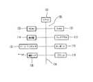
図1は、本実施の形態のチェックアウトシステム101の全体を示す外観斜視図である。チェックアウトシステム101は、1台以上の商品データ入力装置102、複数台のサッカー台103、および1台の決済端末装置104で構成されている。商品データ入力装置102は作業台105の上に設置されている。 FIG. 1 is an external perspective view showing the
また、チェックアウトシステム101は、買物客の自由な出入りを制限する構造となっている。そのための構造として、商品データ入力装置102を載置する複数台の作業台105が、それぞれ平行に配置されて第1の通路となる入口通路106を形成している。そして、入口通路106を通過した買物客がとどまる領域107を取り囲むようにして複数台のサッカー台103がコの字状に設置されている。さらに、決済端末装置104が一台のサッカー台103との間に通路を形成するように隣接して設置されて、この通路が第2の通路となる出口通路108となる。 In addition, the
決済端末装置104は開閉扉109を有しており、通常は開閉扉109を閉塞状態とすることで、出口通路108を買物客が自由に通過することが制限されている。そして、後述するように決済端末装置104で決済処理が終了すると、開閉扉109の閉塞状態は解除されて買物客の通過が許可される。 The
ここで、サッカー台103は、スーパーマーケットなどで袋詰め等のために一般的に使用されているものと何ら変わりがないものである。領域107を取り囲むサッカー台103は、買物客が不正にチェックアウトシステム101外に退出することを防ぐ柵となる。そして、柵をサッカー台103としたことで、例えば買物客が二人で買物に来た場合などに、一人がチェックアウトシステム101でチェックアウトを行い、もう一人がサッカー台103の外から商品の袋詰め作業を手伝うことができる。 Here, the soccer table 103 is not different from what is generally used for bagging in a supermarket or the like. The soccer table 103 surrounding the
図2は、商品データ入力装置102の外観を示す斜視図である。作業台105の上面に設置された商品データ入力装置102は、読取窓112を有する定置式のバーコードスキャナ111をベースに構成されている。読取窓112から出射されたレーザ光等が商品コードであるバーコード上で反射し、その反射光を再び読取窓112から入射させて受光部(図示しない)で受光することで、商品コードの読み取り入力が実行される。 FIG. 2 is a perspective view showing an appearance of the product
また、商品データ入力装置102は、バーコードスキャナ111の上部にタッチパネル113付き表示器114およびキーボード115を備えている。表示器114には入力されたバーコードに基づく商品名および価格等が表示される。タッチパネル113およびキーボード115は、バーコードのラベルを貼れない商品等のように読取窓112によるバーコードの入力に適さない場合の商品データの入力を補助するためものである。 The merchandise
店員側から見て商品データ入力装置102の左側には、プリンタ116が接続されている。プリンタ116は、後述する識別データや一取引分の合計金額等の取引データが印字された伝票R1を発行する。 A
図3は、決済端末装置104の外観を示す斜視図である。決済端末装置104は、本体を正面から見て前方上面に、文字情報を表示して買物客をガイドする表示器121を備え、さらに、表示器121の下方に金銭の投入を受け付ける硬貨投入口122および紙幣投入口123を、正面から見て本体の左側面には金銭の払出をする硬貨払出口124および紙幣払出口125を備えている。なお、決済端末装置104は一般的な硬貨釣銭機および紙幣釣銭機をベースに構成され、その構造及び機能は従来のものと何ら変わるものではないためその説明は省略する。 FIG. 3 is a perspective view showing the appearance of the
また、表示器121の後方、本体の上面には伝票挿入口126とレシート発行口127とが設けられている。伝票挿入口126は、前述した商品データ入力装置102が備えるプリンタ116より発行された伝票R1の挿入を受け付ける。買物客は、プリンタ116から発行された伝票R1を受け取り、受け取った伝票R1を伝票挿入口126に挿入する。 Further, a
決済端末装置104の内部には後述するプリンタユニット151が設けられている。プリンタユニット151は、伝票挿入口126から挿入された伝票R1に、決済端末装置104で実行される決済処理に伴い生ずるデータ(預り金額、釣銭金額など)を印字して、レシートR2としてレシート発行口127から発行する。 A printer unit 151 (to be described later) is provided inside the
決済端末装置104は、本体を正面から見て左側面に開閉扉109を備えている。買物客が、硬貨払出口124または紙幣払出口125から払出された釣銭を受け取り、さらにレシート発行口127からレシートR2が買物客によって受け取られて、決済処理が終了すると、開閉扉109は閉塞状態を解除し、決済端末装置104の後方に扉を開放して、買物客が通行可能な状態を形成する。 The
図4は、商品データ入力装置102の電気的接続を示すブロック図である。商品データ入力装置102は、各部を集中的に制御するCPU131に、コンピュータプログラム等の固定的データを予め格納するROM132及び各種データを書き換え自在に記憶するRAM133がバスライン134を介してバス接続して構成されるマイクロコンピュータ135を保有し、通信インターフェイス136から、LAN等を介して上位装置であるストアコンピュータ(図示しない)および決済端末装置104との間で相互にオンライン通信を実行し得るように構成されている。また、マイクロコンピュータ135には、バスライン134を介して、前述したバーコードスキャナ111、タッチパネル113、表示器114、キーボード115およびプリンタ116が接続されている。 FIG. 4 is a block diagram showing the electrical connection of the product
バーコードスキャナ111により読み取り入力された商品コードに基づき図示しないストアコンピュータのPLUファイルを検索し、該当する商品コードに対応した商品名や単価等が読み出される。また、マイクロコンピュータ135は、後述する識別データを作成して一取引分の取引データに付加させて決済端末装置104へ送信出力する。 A PLU file of a store computer (not shown) is searched based on the product code read and input by the
図5は、決済端末装置104の電気的接続を示すブロック図である。決済端末装置104は、各部を集中的に制御するCPU141に、コンピュータプログラム等の固定的データを予め格納するROM142及び各種データを書き換え自在に記憶するRAM143がバスライン144を介してバス接続して構成されるマイクロコンピュータ145を保有し、通信インターフェイス146から、LAN等を介して上位装置であるストアコンピュータ(図示しない)および1台以上の商品データ入力装置102との間で相互にオンライン通信を実行し得るように構成されている。マイクロコンピュータ145には前述した表示器121が接続され、さらに、開閉扉用駆動モータ147が接続されている。 FIG. 5 is a block diagram showing an electrical connection of the
開閉扉用駆動モータ147は、決済端末装置104に回動自在に設けられた開閉扉109を閉塞状態から開放状態に駆動させる動力源である。後述するように決済端末装置104で決済処理が終了して閉塞状態が解除されると、マイクロコンピュータ145は開閉扉用駆動モータ147を回転させる。この開閉扉用駆動モータ147の回転は、開閉扉用駆動モータ147と開閉扉109の回転軸(図示しない)との間に構成されている動力伝達機構(図示しない)により開閉扉109の回転軸を駆動させて、開閉扉109を決済端末装置104の後方に回動させる。 The open / close
また、決済端末装置104のマイクロコンピュータ145には、不揮発性のフラッシュメモリ148が接続されている。フラッシュメモリ148には、一取引分の取引データと当該取引を識別可能に特定する識別データとが記憶される。商品データ入力装置102は、この識別データを作成すると、取引データに付加させて決済端末装置104に送信する。そして識別データおよび取引データを受信した決済端末装置104のマイクロコンピュータ145は、受信した識別データおよび取引データをフラッシュメモリ148に記憶する。 In addition, a
さらに、投入センサ、材質センサ、払出センサ等のセンサ類149および搬送ローラ等を駆動する各モータ150が接続されて決済端末装置104の貨幣入出金機構を構成し、プリンタユニット151およびプリンタユニット151内に設けられたバーコードスキャナ152も接続されている。 Further,
図6は、決済端末装置104のプリンタユニット151の内部構造を概略的に示す側面図である。伝票挿入口126とレシート発行口127との間にはレシート通路161が設けられている。レシート通路161には搬送ローラ162が設けられていて、伝票挿入口126から挿入された伝票R1を搬送する。 FIG. 6 is a side view schematically showing the internal structure of the
また、レシート通路161にはバーコードスキャナ152が設けられていて、伝票R1にコードシンボル化して印字された後述する識別データを読み取ることができる。そして、レシート通路161には、プラテンローラ163、印字ヘッド164およびセンサ165が設けられ、伝票R1への印字を可能としている。なお、レシート通路161のレシート発行口127の近傍には、カッタ166およびセンサ167が設けられており、伝票R1のバーコードが印字された部位が切り取られる。 In addition, a
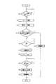
図7は、商品データ入力装置102で行われる商品コード入力処理の流れを示すフローチャートである。商品データ入力装置102のバーコードスキャナ111によって商品に付された商品コードの読み取り入力がなされると、読み取り入力された商品コードに基づいてPLUファイルを検索し、該当する商品コードに対応した商品名や単価等を読み出し、商品コード及び読み出した商品名や単価等をRAM133のワークエリアに記録して、読み出した単価を加算して合計金額を算出し、この処理を締めキー(図示しない)が押下されるまで繰り返す。そして、締めキーが押下されると(ステップS1のY)、商品データ入力装置102のマイクロコンピュータ135は、一取引分の取引データと当該取引を特定することができる識別データを作成する(ステップS2)。 FIG. 7 is a flowchart showing the flow of the product code input process performed by the product
ここで、識別データについて説明する。識別データは、一取引の合計金額、取引商品の商品データ入力処理が行われた商品データ入力装置102の固有番号および商品データ入力処理が行われた日時などによって、一取引を識別できる取引ごとに固有のデータである。 Here, the identification data will be described. The identification data is determined for each transaction that can identify one transaction based on the total amount of one transaction, the unique number of the product
次いで、一取引分の取引データに付加させて識別データを、決済端末装置104のフラッシュメモリ148に記憶させるため、決済端末装置104に送信出力する(ステップS3)。識別データおよび取引データを受信した決済端末装置104のマイクロコンピュータ145は、受信した取引データに付加させて識別データをフラッシュメモリ148に記憶する。 Next, the identification data added to the transaction data for one transaction is transmitted and output to the
さらに、商品データ入力装置102のマイクロコンピュータ135は、作成された識別データをバーコードにコードシンボル化する(ステップS4)。そして、プリンタ116によって、バーコードと商品の合計金額等の取引データとを印字した伝票R1を発行する(ステップS5)。 Furthermore, the
図8は、図7のフローチャートのステップS6でプリンタ116から発行された伝票R1の一例を示す模式図である。伝票R1の最下部には、図7のフローチャートのステップS5でコードシンボル化された識別データのバーコードが印字されている。また、商品の合計金額(合計)とバーコードとの間に印字スペースとしての空欄が設けられている。 FIG. 8 is a schematic diagram showing an example of the slip R1 issued from the
図9は、決済端末装置104によって行われる処理の流れを示すフローチャートである。図7のフローチャートのステップS6で発行された伝票R1が伝票挿入口126から挿入されると(ステップS11)、伝票R1に印字されている識別データのバーコードをバーコードスキャナ152が読み取る(ステップS12)。次いで、決済端末装置104のCPU141は、フラッシュメモリ148にアクセスして商品データ入力装置102から送信されて記憶した識別データを検索する(ステップS13)。ここで、ステップS12で読み取った識別データと同じ識別データがフラッシュメモリ148に記憶されていれば(ステップS14のY)、この識別データに対応した一取引分の合計金額を表示器121に表示して、硬貨投入口122および紙幣投入口123により金銭の投入を受け付ける(ステップS15)。 FIG. 9 is a flowchart showing a flow of processing performed by the
しかし、該当する識別データがフラッシュメモリ148に記憶されていなければ(ステップS14のN)、伝票挿入口126から挿入された伝票R1を、再び伝票挿入口126より返却する(ステップS16)。 However, if the corresponding identification data is not stored in the flash memory 148 (N in Step S14), the slip R1 inserted from the
ステップS14で該当する識別データがあり、表示器121に表示された合計金額以上の金額投入がなされたら(ステップS15のY)、投入金額から合計金額を減算した差額を釣銭金額として、硬貨払出口124および紙幣払出口125から払出す(ステップS17)。そして、決済処理に伴い生成されるデータである投入金額(預り金額)と釣銭金額とを伝票挿入口126から挿入された伝票R1に設けられた空欄にプリンタユニット151によって印字し、さらに伝票R1のコードシンボル化された識別データが印字された部位をプリンタユニット151内のカッタ166が切り取って、レシートR2としてレシート発行口127から発行する(ステップS18)。 If there is corresponding identification data in step S14 and an amount greater than the total amount displayed on the
レシート発行口127から発行されたレシートR2が買物客によって抜き取られたならば(ステップS19のY)、決済端末装置104は決済処理を終了して、フラッシュメモリ148から当該識別データを消去し(ステップS20)、開閉扉109の閉塞状態を解除して扉を開放する(ステップS21)。そして、買物客の通過を許可し、通過が確認されると再び開閉扉109を閉めて閉塞状態として処理を終了する。 If the receipt R2 issued from the
図10は、図9のフローチャートのステップS18でレシート発行口127から発行されたレシートR2の一例を示す模式図である。伝票R1で設けられていた空欄に、預り金額と釣銭金額とのデータが新たに印字されている。また、伝票R1でバーコードが印字されていた部位が切り取られているため、伝票R1と比較して、縦方向の長さが短くなっている。 FIG. 10 is a schematic diagram showing an example of the receipt R2 issued from the
以上説明したように、本実施の形態によれば、1台の決済端末装置104が1台以上の商品データ入力装置102に対応するため、店員の負担を軽減できるチェックアウトシステム101を安価に提供できる。 As described above, according to the present embodiment, since one
そして、決済端末装置104に開閉扉109が備えられており、また周囲を一般的なサッカー台103で囲うため、チェックアウトシステム101の構成が簡易であり、他に特別な装置や設置工事等を必要とせず、システムの導入を比較的容易に行うことができる。 The
買物客は、合計金額が印字された伝票R1を一度受けとってから、購入した商品の袋詰めをして、決済を行うため、合計金額を確認して予め支払うべき金額を準備でき、決済端末装置104での決済作業もスムーズに行うことができる。 The shopper receives the slip R1 on which the total amount is printed, and then packs the purchased product for payment, so that the customer can check the total amount and prepare the amount to be paid in advance. The settlement operation at 104 can be performed smoothly.
また、買物客が自ら商品データの入力処理を実行するセルフ式の商品データ入力装置を用いることで、セルフチェックアウトシステムへの適用も可能である。 Further, by using a self-type merchandise data input device in which a shopper executes merchandise data input processing, the present invention can be applied to a self-checkout system.
なお、本実施の形態のチェックアウトシステム101では、現金決済のみ可能である決済端末装置104を用いたが、別の実施形態として、決済端末装置104に各種カードリーダライタを設けて、電子マネー決済、プリペイドカード決済、デビットカード決済等に対応したチェックアウトシステムとすることができることは言うまでもない。また、本実施の形態では、取引データ等が記憶される記憶装置であるフラッシュメモリ148を決済端末装置104に設けたチェックアウトシステム101について述べたが、記憶装置はフラッシュメモリ148に限定されるものではない。さらに、フラッシュメモリ148等の記憶装置は、決済処理端末104ではなく、商品データ入力装置102に設けられていてもよいし、商品データ入力装置102および決済端末装置104と通信可能に接続された他の機器等に設けられていてもよい。
In the
チェックアウトシステム…101,商品データ入力装置…102,サッカー台…103,決済端末装置…104,第1の通路(入口通路)…106,領域…107,第2の通路(出口通路)…108,開閉扉…109,商品データ読取装置(バーコードスキャナ)…111,第1のプリンタ(プリンタ)…116,記憶装置(フラッシュメモリ)…148,第2のプリンタ(プリンタユニット)…151,読取装置(バーコードスキャナ)…152,カッタ…166
Checkout system ... 101, commodity data input device ... 102, soccer table ... 103, payment terminal device ... 104, first passage (entrance passage) ... 106, region ... 107, second passage (exit passage) ... 108, Opening / closing door ... 109, commodity data reading device (barcode scanner) ... 111, first printer (printer) ... 116, storage device (flash memory) ... 148, second printer (printer unit) ... 151, reading device ( Barcode scanner) ... 152, cutter ... 166
Claims (4)
Translated fromJapanese前記商品データ入力装置は、
商品データを読み取る商品データ読取装置と、
前記商品データ読取装置によって読み取られた商品データに基づく一取引分の取引データと当該一取引を特定する識別データとを作成し、記憶装置に記憶する手段と、
第1のプリンタと、
前記識別データをコードシンボルデータに変換する手段と、
一取引分の取引データの下に空欄を設け前記コードシンボルデータに基づくコードシンボルを記録した可搬性を有する媒体を、前記第1のプリンタから印字発行させる手段と、
を備え、
前記決済端末装置は、
前記媒体に記録されたデータを読み取る読取装置と、
前記商品データ入力装置によって前記媒体に記録された前記コードシンボルを前記読取装置に読み取らせ、対応する前記取引データを特定する特定手段と、
特定された前記取引データに基づく決済処理を実行する決済手段と、
第2のプリンタと、
前記空欄に、前記決済処理に伴い生成される情報を前記第2のプリンタに印字発行させる手段と、
を備える、チェックアウトシステム。A checkout system comprising at least one product data input device and a payment terminal device,
The product data input device includes:
A product data reader for reading product data;
Means for creating transaction data for one transaction based on the product data read by the product data reading device and identification data for identifying the one transaction, and storing the data in a storage device;
A first printer;
Means for converting the identification data into code symbol data;
Means for printing and issuing a portable medium having a blank space under transaction data for one transaction and recording a code symbol based on the code symbol data from the first printer;
With
The payment terminal device
A reader for reading data recorded on the medium;
Specifying means for causing the reading device to read thecode symbol recorded on the medium by the commodity data input device and specifying the corresponding transaction data;
A payment means for executing a payment process based on the identified transaction data;
A second printer;
Means for causing the second printer to print and issue information generated with the payment process in the blank;
Acheckout system comprising:
カッタと、
前記コードシンボル部位を前記カッタによって切り取らせる手段と、
を備える、
請求項1記載のチェックアウトシステム。The second printer is
With cutter,
Means for cutting the code symbol portion by the cutter;
Comprising
The checkout system according to claim1 .
前記第1の通路を通過した買物客をとどまらせる領域と、
前記決済端末装置と共に前記領域を取り囲んで配列された複数台のサッカー台と、
前記決済端末装置と当該決済端末装置に隣り合う前記サッカー台との間に形成され、前記領域から買物客を出口に導く第2の通路と、
前記第2の通路に位置付けられて、当該第2の通路を開閉自在に覆う開閉扉と、
前記開閉扉を閉塞状態にする手段と、
前記決済端末装置による決済処理が終了すると、前記開閉扉の前記閉塞状態を解除する手段と、
を備える請求項2記載のチェックアウトシステム。A first passage formed along the commodity data input device for passing a shopper;
An area for retaining the shopper who has passed through the first passage;
A plurality of soccer stands arranged around the area together with the settlement terminal device;
A second passage formed between the settlement terminal device and the soccer table adjacent to the settlement terminal device, and leading a shopper from the area to an exit;
An opening / closing door that is positioned in the second passage and covers the second passage so as to be freely opened and closed;
Means for closing the open / close door;
When the payment processing by the payment terminal device is completed, means for releasing the closed state of the door
The checkout system according to claim 2, further comprising:
。The checkout system according to claim 3, wherein the settlement terminal device includes the storage device.
Priority Applications (1)
| Application Number | Priority Date | Filing Date | Title |
|---|---|---|---|
| JP2005170853AJP4704119B2 (en) | 2005-06-10 | 2005-06-10 | Checkout system |
Applications Claiming Priority (1)
| Application Number | Priority Date | Filing Date | Title |
|---|---|---|---|
| JP2005170853AJP4704119B2 (en) | 2005-06-10 | 2005-06-10 | Checkout system |
Publications (2)
| Publication Number | Publication Date |
|---|---|
| JP2006344123A JP2006344123A (en) | 2006-12-21 |
| JP4704119B2true JP4704119B2 (en) | 2011-06-15 |
Family
ID=37641026
Family Applications (1)
| Application Number | Title | Priority Date | Filing Date |
|---|---|---|---|
| JP2005170853AExpired - Fee RelatedJP4704119B2 (en) | 2005-06-10 | 2005-06-10 | Checkout system |
Country Status (1)
| Country | Link |
|---|---|
| JP (1) | JP4704119B2 (en) |
Families Citing this family (10)
| Publication number | Priority date | Publication date | Assignee | Title |
|---|---|---|---|---|
| JP5230169B2 (en)* | 2007-11-22 | 2013-07-10 | グローリー株式会社 | Cash management system and automatic change machine |
| JP2011253234A (en)* | 2010-05-31 | 2011-12-15 | Teraoka Seiko Co Ltd | Pos register and pos system |
| JP5750840B2 (en)* | 2010-06-17 | 2015-07-22 | 株式会社寺岡精工 | Settlement device and POS system |
| JP5691473B2 (en)* | 2010-12-13 | 2015-04-01 | 株式会社寺岡精工 | Checkout device, product registration device, and checkout system |
| JP6247238B2 (en) | 2015-02-06 | 2017-12-13 | 東芝テック株式会社 | Checkout system, settlement apparatus and program thereof |
| JP6426536B2 (en)* | 2015-06-10 | 2018-11-21 | 東芝テック株式会社 | Product sales data processing device |
| JP6927711B2 (en)* | 2017-02-20 | 2021-09-01 | 東芝テック株式会社 | Checkout system |
| JP6517284B2 (en)* | 2017-08-02 | 2019-05-22 | 東芝テック株式会社 | Product data registration device and program |
| JP6449493B2 (en)* | 2018-02-13 | 2019-01-09 | 東芝テック株式会社 | Checkout system, product registration device, and control program |
| WO2025062567A1 (en)* | 2023-09-21 | 2025-03-27 | 日本電気株式会社 | Information processing device, settlement device, checkout system, information processing method, settlement method, and non-transitory computer-readable recording medium |
Family Cites Families (3)
| Publication number | Priority date | Publication date | Assignee | Title |
|---|---|---|---|---|
| JPH08190671A (en)* | 1995-01-12 | 1996-07-23 | Omron Corp | Transaction processing system |
| JPH11151371A (en)* | 1997-11-20 | 1999-06-08 | Pfu Ltd | Prize management system |
| JP2004058323A (en)* | 2002-07-25 | 2004-02-26 | Star Micronics Co Ltd | Printer |
- 2005
- 2005-06-10JPJP2005170853Apatent/JP4704119B2/ennot_activeExpired - Fee Related
Also Published As
| Publication number | Publication date |
|---|---|
| JP2006344123A (en) | 2006-12-21 |
Similar Documents
| Publication | Publication Date | Title |
|---|---|---|
| CA1290453C (en) | Cashierless checkout system | |
| EP0348484B1 (en) | Checkout system and method | |
| US6363355B1 (en) | Method and apparatus for operating a self-service checkout system having a number of retail terminals associated therewith | |
| JP4704119B2 (en) | Checkout system | |
| JP6927711B2 (en) | Checkout system | |
| EP3824449A1 (en) | Modular automated transaction machine | |
| JP2010086158A (en) | Cash register settlement system | |
| JP4210688B2 (en) | Cash-out processing method and cash-out processing system | |
| JPH06243340A (en) | Self check-out system | |
| JP3578868B2 (en) | Checkout system | |
| KR20070014380A (en) | POS system using portable wireless terminal | |
| JP3613522B2 (en) | Card processing apparatus and card settlement system | |
| JP2001143159A (en) | Product sales registration data processing device | |
| JPS60263295A (en) | Self-checkout gate | |
| JP5242269B2 (en) | Sales deposit system and sales deposit method | |
| CN100481138C (en) | Merchandise sales data processing apparatus | |
| KR980010885A (en) | Automatic unloading system and system | |
| JP2017010407A (en) | Merchandise sales data processing system and merchandise sales data processor | |
| JP2007025747A (en) | Printing apparatus and POS system | |
| JP4753598B2 (en) | Automatic transaction equipment | |
| JP7549090B2 (en) | Gift certificate management system | |
| JP7698112B2 (en) | Accounting Equipment | |
| JP6209895B2 (en) | Settlement system, settlement apparatus and program | |
| JP6542434B2 (en) | Duty-free processing system, acceptance device and program | |
| JPH02148292A (en) | Card vendor |
Legal Events
| Date | Code | Title | Description |
|---|---|---|---|
| A621 | Written request for application examination | Free format text:JAPANESE INTERMEDIATE CODE: A621 Effective date:20080130 | |
| RD02 | Notification of acceptance of power of attorney | Free format text:JAPANESE INTERMEDIATE CODE: A7422 Effective date:20091030 | |
| RD04 | Notification of resignation of power of attorney | Free format text:JAPANESE INTERMEDIATE CODE: A7424 Effective date:20100129 | |
| A131 | Notification of reasons for refusal | Free format text:JAPANESE INTERMEDIATE CODE: A131 Effective date:20101214 | |
| A521 | Request for written amendment filed | Free format text:JAPANESE INTERMEDIATE CODE: A523 Effective date:20110210 | |
| A01 | Written decision to grant a patent or to grant a registration (utility model) | Free format text:JAPANESE INTERMEDIATE CODE: A01 Effective date:20110308 | |
| A61 | First payment of annual fees (during grant procedure) | Free format text:JAPANESE INTERMEDIATE CODE: A61 Effective date:20110309 | |
| LAPS | Cancellation because of no payment of annual fees |