JP4703907B2 - Object surface grid generation method - Google Patents
Object surface grid generation methodDownload PDFInfo
- Publication number
- JP4703907B2 JP4703907B2JP2001232017AJP2001232017AJP4703907B2JP 4703907 B2JP4703907 B2JP 4703907B2JP 2001232017 AJP2001232017 AJP 2001232017AJP 2001232017 AJP2001232017 AJP 2001232017AJP 4703907 B2JP4703907 B2JP 4703907B2
- Authority
- JP
- Japan
- Prior art keywords
- lattice
- orthogonal
- grid
- data
- size
- Prior art date
- Legal status (The legal status is an assumption and is not a legal conclusion. Google has not performed a legal analysis and makes no representation as to the accuracy of the status listed.)
- Expired - Fee Related
Links
Images


Description
Translated fromJapanese【0001】
【発明の属する技術分野】
本発明は、CAD、FEM、計測データ等の多様な形状データから表面格子を生成する物体の表面格子生成方法に関する。
【0002】
【従来の技術】
従来、CAE等の数値シミュレーションにおける物体形状の認識技術として、物体の表面形状を三次元の直交格子で定義する技術がある。この技術では、例えば特開平11−25293号公報等に開示されているように、形状データの直交格子に対する内外判定を行って表面格子を生成するのが一般的である。
【0003】
【発明が解決しようとする課題】
しかしながら、従来の技術では、予め内外判定の計算に必要なデータ形式で物体の形状データを作成する必要があり、データ作成作業に多大な労力を要するばかりでなく、入力データ形式を特定しなければならないことから、CAD、FEM、計測データ等の多様な形状データを共有することが困難であった。更には、内外判定に複雑な計算を要するため、精度を確保するためには高価なシステムが必要となる。
【0004】
本発明は上記事情に鑑みてなされたもので、CAD、FEM、計測データ等の多様な形状データから複雑な内外判定を行うことなく容易且つ精度良く表面格子を生成することのできる物体の表面格子生成方法を提供することを目的としている。
【0005】
【課題を解決するための手段】
上記目的を達成するため、請求項1記載の発明は、物体の表面形状を表現する表面格子をコンピュータが生成する物体の表面格子生成方法であって、上記物体の表面形状データを読み込み、読み込んだ表面形状データを指定された直交格子のサイズ以下の複数の三角形要素に細分化するステップと、上記複数の三角形要素のそれぞれを代表する点群を上記物体の表面形状に沿って配置するステップと、上記点群の中の各点が上記直交格子の内側にあるか否かを判定するステップと、上記点群の中の点が内側にあると判定された直交格子を上記物体の表面格子と定義するステップと、上記表面格子の位置を、物体の厚さに近い格子数に基づいて調整するステップとを有することを特徴とする。
【0006】
請求項2記載の発明は、請求項1記載の発明において、上記複数の三角形要素に細分化するステップは、三角形の中線のうちの最も短い中線で2分割することを繰返して上記表面形状データを上記直交格子のサイズ以下の複数の三角形要素に細分化することを特徴とする。
【0007】
請求項3記載の発明は、請求項1記載の発明において、上記複数の三角形要素に細分化するステップは、三角形の各辺の中点を結んで得られる4つの相似形の三角形に分割することを繰返して上記表面形状データを上記直交格子のサイズ以下の複数の三角形要素に細分化することを特徴とする。
【0008】
請求項4記載の発明は、請求項3記載の発明において、上記直交格子に含まれる点の数から上記物体の表面積を算出し、この表面積を格子情報として付加するステップを更に有することを特徴とする。
【0009】
請求項5記載の発明は、請求項1,2,3,4のいずれか一に記載の発明において、上記表面格子の位置を調整するステップは、物体の厚さを上記直交格子のサイズで除算し、この除算値に最も近い整数値を上記物体の厚さに近い格子数として求め、上記整数値が物体を含む直交格子の厚さになるように表面格子の位置をオフセットさせることを特徴とする。
【0010】
請求項6記載の発明は、請求項1,2,3,4,5のいずれか一に記載の発明において、上記表面格子に、物体の物理的特性情報を付加するステップを更に有することを特徴とする。
【0011】
【発明の実施の形態】
以下、図面を参照して本発明の実施の形態を説明する。図1〜図5は本発明の実施の第1形態に係わり、図1は表面格子生成システムの構成図、図2は表面格子生成処理のフローチャート、図3は多角形の面データの三角形要素への分割を示す説明図、図4は三角形要素の細分化処理の説明図、図5は三角形要素の他の細分化処理の説明図である。
【0012】
図1において、符号1は、直交格子から物体の形状を定義する表面格子データを生成する表面格子生成システムの概略構成を示すものであり、システム全体を制御すると共に表面格子データ生成のための各種処理を実行するCPU2、処理途中の一時データ等を格納するメモリ3、磁気ディスク装置等の主記憶装置4を備えるワークステーション本体5を中心として構成される。
【0013】
ワークステーション本体5には、画像を表示するためのディスプレイ6、数値・文字や各種処理の操作情報を入力するためのキーボード7、ディスプレイ6上に表示された画像の位置等を指示するためのポインティング装置としてのマウス8、処理すべき形状データ等を記憶した外部記憶装置9、生成した格子データを格納するための外部記憶装置10等が接続されている。
【0014】
この表面格子生成システム1で解析可能な形状データは、CADデータ、FEMモデルデータ、実測形状データ等であり、物体の表面形状に沿って発生させた点群データを、直交格子の内外判定に利用し、点群データの中の点が直交格子の内部に含まれれば物体表面、含まれなければ空間と判断することで、直交格子における物体の表面情報を定義する。
【0015】
詳細には、物体の表面形状データを、直交格子のサイズ以下となるまで三角形要素で細分化し、各三角形要素を代表する点を物体形状を定義するための点群データとして配置する。そして、点群における各点が直交格子の内側にあるか外側にあるかをチェックし、点が直交格子の内側にあれば、その点を含む直交格子を物体の表面格子として定義する。
【0016】
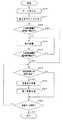
以下、表面格子データの生成処理について、図2のフローチャートを用いて説明する。
【0017】
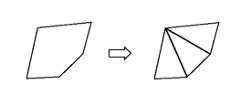
この処理では、先ず、ステップS1で、外部記憶装置9から物体の形状データを入力データとして読込み、ステップS2で物体の形状データを複数個の任意の三角形要素に分割する。具体的には、物体の形状データが多角形、例えば、図3に示すように五角形である場合、この五角形で表される物体の形状データを3つの三角形に分割する。すなわち、処理すべきデータを一種類とし、しかも幾何学的に最小単位の三角形とすることで、以下に述べる三角形の細分化や点群データの配置を容易とする。尚、物体の形状データが既に三角形要素で定義されている場合には、このステップS2の処理は必要ない。
【0018】
次に、ステップS3へ進むと、直交格子のサイズ(格子幅)と直交格子全体の領域を指定し、ステップS4で、三角形の大きさが直交格子の幅以下か否かを調べる。ここで、三角形の大きさは、三角形の最も長い辺、中線の長さ、外接円の直径等で代表するものである。そして、三角形の大きさが直交格子の幅以下の場合には、ステップS4からステップS7へジャンプし、三角形の大きさが直交格子の幅以下でない場合、ステップS4からステップS5へ進む。
【0019】
ステップS5では、物体表面の三角形要素を更に分割して細分化し、ステップS6で、再度、三角形の大きさが直交格子の幅以下か否かを調べる。そして、三角形の大きさが直交格子の幅以下でないときには、ステップS5へ戻り、三角形の細分化を進める。
【0020】
この三角形の細分化処理は、例えば、以下の(1),(2)で説明するように、三角形を最短の中線で分割する手法、或いは3辺の中点で分割する手法を用いる。
【0021】
(1)最短の中線で分割
図4に示すように、一つの三角形を、その最短の中線で2つの三角形に分割し、分割した2つの三角形の各々を最短の中線で更に分割するといった処理を、物体表面の全ての三角形要素の大きさが直交格子の幅以下となるまで繰返す。この手法では、元の三角形が扁平率の大きい三角形、すなわち歪んだ三角形であっても、より扁平率の小さい、均等に近い三角形に分割することができる。従って、分割回数を少なくすることが可能であり、処理効率を向上することができる。
【0022】
(2)3辺の中点で分割
図5に示すように、一つの三角形を、その3辺の中点を結んでできる相似形の新たな三角形a,b,c,dで4つに分割し、分割した4つの三角形a,b,c,dの各々を、3辺の中点を結んでできる相似の三角形で更に4つに分割するといった処理を、物体表面の全ての三角形要素の大きさが直交格子の幅以下となるまで繰返す。この手法では、三角形が相似形に分割され、分割した三角形の面積が分割前の三角形の面積の1/分割数となるため、直交格子に含まれる三角形の数(点データの数)から物体の表面積を近似的に算出することができ、物体の表面積を格子情報として与えることができる。
【0023】
次に、以上により、細分化した三角形の大きさが直交格子の幅以下になったとき、ステップS5からステップS7へ進み、分割された各三角形を代表する点を、物体形状を定義するための点群データとして配置する。各三角形を代表する点群は、各三角形の重心、頂点、内接円又は外接円の中心等である。
【0024】
続くステップS8では、配置された各点のデータが直交格子の内側にあるか外側にあるかの判定を行う。その結果、点データが直交格子の外側であれば、ステップS11へジャンプし、点データが直交格子の内側にあれば、ステップS9で、その点を含む直交格子を物体の表面格子として定義する。そして、ステップS10へ進み、必要に応じて物体の材質、板厚、重量等の格子情報を表面格子に付け加え、ステップS11で、全部の点データについて上述の判定処理を実施したか否かを調べる。
【0025】
その結果、全部の点データについての判定処理が終了していない場合には、前述のステップS8に戻り、全部の点データについての判定処理が終了した場合、ステップS12へ進む。ステップS12では、全部の三角形要素について上述の処理を実施したか否かを調べる。そして、未だ全部の三角形要素について処理を終了していない場合には、ステップS7へ戻り、全部の三角形要素について処理を終了した場合、ステップS12から抜けて処理を終了する。
【0026】
以上の処理により、物体表面形状を三角形要素で細分化して格子幅以下の点群データを発生させ、各点の直交格子に対する位置関係を調べて物体形状を定義する表面格子を生成するため、従来のような線或いは面による複雑な内外判定の計算を行うことなく、簡単且つ精度高く物体を定義することができる。
【0027】
しかも、物体がどんな形状であっても、表面形状に沿った点群を発生させることは可能であるため、入力データ形式を選ぶことなく、多様なデータを共有することとができる。また、表面格子に物体の物理的特性を付加することで、各種解析計算やポスト処理を行う際の条件として用いることができる。
【0028】
図6は本発明の実施の第2形態に係わり、表面格子生成処理のフローチャートである。
【0029】
第2形態は、三次元スキャナ等により物体表面の形状データを点群データとして取得し、この点群データを入力データとして処理して表面格子データを生成するものである。
【0030】
以下、第2形態における表面格子生成処理について、図6のフローチャートを用いて説明する。この処理では、ステップS20において、図示しないスキャナ等で生成された物体表面の点群データを読込み、ステップS21で、直交格子のサイズ(格子幅)と直交格子全体の領域を指定する。次いで、ステップS22へ進み、読込んだ点群データの中で最も近い2点間の距離が直交格子の幅以下か否かを調べる。
【0031】
そして、2点間の距離が直交格子の幅以下の場合には、ステップS22からステップS25へジャンプし、2点間の距離が直交格子よりも大きい場合、ステップS22からステップS23へ進んで2点の間に新たな点を補間し、ステップS24で、再度、補間した新たな点と元の2点のうちの近い方の点との間の距離が直交格子の幅以下か否かを調べる。その結果、2点間の距離が直交格子よりも大きい場合には、ステップS22へ戻って2点間の補間を繰返し、2点間の距離が直交格子以下になったとき、ステップS25へ進んで各点のデータが直交格子の内側にあるか外側にあるかの判定を行う。
【0032】
その結果、点データが直交格子の外側であれば、ステップS25からステップS28へジャンプし、点データが直交格子の内側にあれば、ステップS25からステップS26へ進んで、その点を含む直交格子を物体の表面格子として定義する。次いで、ステップS27へ進み、必要に応じて物体の材質、板厚、重量等の物理的特性情報を表面格子に付加し、ステップS28で、全部の点データについて上述の判定処理を実施したか否かを調べる。そして、全部の点データについての判定処理が終了していない場合には、前述のステップS25に戻り、全部の点データについての判定処理が終了した場合、ステップS28から抜けて処理を終了する。
【0033】
第2形態では、従来のような面データが無くとも、点だけのデータから格子生成ができるため、入力データを選ばないという利点に加え、補間する点の数により形状表現精度を制御することができることから、より適応範囲の広い柔軟なシステムを実現することができる。
【0034】
図7及び図8は本発明の実施の第3形態に係わり、図7は表面格子生成処理の部分フローチャート、図8は板厚を考慮した格子位置の調整を示す説明図である。
【0035】
第3形態は、前述の第1形態に対し、物体形状の厚さが重要となる場合に対処するものである。すなわち、厚さのある物体に対し、その表面データから格子データを生成すると、直交格子と物体表面との位置関係によっては、物体の実寸法の厚さを近似した格子数に比べて大きくなってしまうことがある。このような場合、表面格子の位置よりも、厚さ方向の格子数を優先させ、実寸法を近似した格子数で表面格子の位置を調整する。
【0036】
このため、第3形態の表面格子生成処理では、第1形態の表面格子生成処理(図2参照)において格子情報を付加するステップS10の後に、物体の厚さに応じた補正を加えるためのステップ(S10−1)を追加する。
【0037】
すなわち、図7のフローチャートに示すように、第1形態と同様のステップS1〜S6を経てステップS7で点群データを配置した後、ステップS8で、配置された各点のデータが直交格子の内側にあるか外側にあるかの判定を行い、点データが直交格子の外側であれば、ステップS11へジャンプし、点データが直交格子の内側にあれば、ステップS9で、その点を含む直交格子を物体の表面格子として定義する。そして、ステップS10で、物体の材質、板厚、重量等の付加情報を表面格子に付け加えた後、ステップS10−1へ進み、厚さ方向の実寸法を近似した格子数で表面格子の位置を補正し、第1形態と同様のステップS11,S12を経て処理を終了する。
【0038】
例えば、図8(a)に示すように、物体の厚さdが格子のサイズδより厚い場合(d>δ)、物体の表面データから直交格子を生成すると、図8(b)に示すように、厚さD1の物体の直交格子が生成される。従って、物体の実寸厚さdを格子サイズδで除算した値に最も近い整数値D2と、物体の直交格子の厚さD1とを比較し、D1=D2のとき、先に生成した表面格子の位置はそのままとし、D1>D2のときには、物体表面と直交格子の位置関係を調べて表面格子の位置を調整する。
【0039】
この格子位置の調整は、図8(c)に示すように、厚さD1の表面格子の両端における物体との位置の差Δd1,Δd2を比較することで行い、Δd1>Δd2のとき、Δd1側の表面格子をΔd2側に1格子分だけオフセットさせ、図8(d)に示すように、D1=D2となるように調整する。
【0040】
第3形態では、物体の厚さの実寸法に最も近い格子数で物体を定義するため、厚さが重要な要素となる部品について、表面形状データから厚さを考慮した格子生成が可能となり、より精度高く物体を定義することができる。
【0041】
【発明の効果】
以上説明したように本発明によれば、物体表面形状を直交格子のサイズ以下まで三角形要素で細分化して点群データを発生させ、各点の直交格子に対する位置関係を調べて物体形状を定義する表面格子を生成するので、複雑な内外判定を行うことなく、多様な形状データから容易且つ精度良く表面格子を生成することができる。
【図面の簡単な説明】
【図1】本発明の実施の第1形態に係わり、表面格子生成システムの構成図
【図2】同上、表面格子生成処理のフローチャート
【図3】同上、多角形の面データの三角形要素への分割を示す説明図
【図4】同上、三角形要素の細分化処理の説明図
【図5】同上、三角形要素の他の細分化処理の説明図
【図6】本発明の実施の第2形態に係わり、表面格子生成処理のフローチャート
【図7】本発明の実施の第3形態に係わり、表面格子生成処理の部分フローチャート
【図8】同上、板厚を考慮した格子位置の調整を示す説明図
【符号の説明】
1 表面格子生成システム
5 ワークステーション本体
9,10 外部記憶装置
d 物体の厚さ
δ 格子サイズ[0001]
BACKGROUND OF THE INVENTION
The present invention relates to an object surface grid generation method for generating a surface grid from various shape data such as CAD, FEM, and measurement data.
[0002]
[Prior art]
Conventionally, as a technique for recognizing an object shape in numerical simulation such as CAE, there is a technique for defining a surface shape of an object with a three-dimensional orthogonal lattice. In this technique, as disclosed in, for example, Japanese Patent Laid-Open No. 11-25293, a surface lattice is generally generated by performing inside / outside determination on an orthogonal lattice of shape data.
[0003]
[Problems to be solved by the invention]
However, in the prior art, it is necessary to create object shape data in a data format necessary for calculation of inside / outside judgment in advance, and not only does the data creation work require much effort, but also the input data format must be specified. Therefore, it is difficult to share various shape data such as CAD, FEM, measurement data, and the like. Furthermore, since complicated calculation is required for the inside / outside determination, an expensive system is required to ensure accuracy.
[0004]
The present invention has been made in view of the above circumstances, and a surface grating of an object that can easily and accurately generate a surface grating from various shape data such as CAD, FEM, and measurement data without performing complicated inside / outside determination. It aims to provide a generation method.
[0005]
[Means for Solving the Problems]
To achieve the above object, a first aspect of the present invention, a surface mesh generation method of the object of producing a surface grid representing the object surface shapecomputer reads the surface shape data of the object, read Subdividing the surface shape data into a plurality of triangular elements having a size equal to or less than a specified orthogonal lattice size, arranging a point group representing each of the plurality of triangular elements along the surface shape of the object, Determining whether each point in the point cloud is inside the orthogonal grid, and defining the orthogonal grid in which the point in the point cloud is determined to be inside is the surface grid of the object And a step ofadjusting the position of the surface grating based on the number of gratings close to the thickness of the object .
[0006]
According to a second aspect of the present invention, in the first aspect of the invention, inthe step of subdividing the plurality of triangular elements, thesurface shape is repeated by repeatedly dividing the triangularshape into two at the shortest middle line.The data is subdivided into a plurality of triangular elements having a size equal to or smaller than the size of the orthogonal lattice .
[0007]
In the invention described in
[0008]
Invention of
[0009]
According to a fifth aspect of the present invention, in the invention according to any one of the first, second, third, and fourth aspects,the step of adjusting the position of the surface gratingdivides the thickness of the object by the size of the orthogonal grating. The integer value closest to the division value is obtained as the number of lattices close to the thickness of the object, and the position of the surface lattice is offset so that the integer value becomes the thickness of the orthogonal lattice including the object. To do.
[0010]
The invention according to
[0011]
DETAILED DESCRIPTION OF THE INVENTION
Embodiments of the present invention will be described below with reference to the drawings. 1 to 5 relate to a first embodiment of the present invention, FIG. 1 is a block diagram of a surface grid generation system, FIG. 2 is a flowchart of surface grid generation processing, and FIG. 3 is a triangular element of polygonal surface data. FIG. 4 is an explanatory diagram of a triangular element subdivision process, and FIG. 5 is an explanatory diagram of another subdivision process of a triangular element.
[0012]
In FIG. 1,
[0013]
The workstation body 5 has a
[0014]
The shape data that can be analyzed by the surface
[0015]
More specifically, the surface shape data of the object is subdivided with triangular elements until the size is smaller than the size of the orthogonal lattice, and points representing each triangular element are arranged as point cloud data for defining the object shape. Then, it is checked whether each point in the point group is inside or outside the orthogonal lattice. If the point is inside the orthogonal lattice, the orthogonal lattice including the point is defined as the surface lattice of the object.
[0016]
Hereinafter, the surface grid data generation process will be described with reference to the flowchart of FIG.
[0017]
In this process, first, in step S1, object shape data is read from the
[0018]
In step S3, the size of the orthogonal lattice (grid width) and the entire area of the orthogonal lattice are designated. In step S4, it is checked whether the size of the triangle is equal to or smaller than the width of the orthogonal lattice. Here, the size of the triangle is represented by the longest side of the triangle, the length of the middle line, the diameter of the circumscribed circle, and the like. If the triangle size is equal to or smaller than the width of the orthogonal lattice, the process jumps from step S4 to step S7. If the triangle size is not equal to or smaller than the width of the orthogonal lattice, the process proceeds from step S4 to step S5.
[0019]
In step S5, the triangular element on the object surface is further divided and subdivided. In step S6, it is checked again whether the size of the triangle is equal to or smaller than the width of the orthogonal lattice. If the size of the triangle is not less than or equal to the width of the orthogonal lattice, the process returns to step S5, and the triangle is further subdivided.
[0020]
For example, as described in the following (1) and (2), the triangle segmentation process uses a technique of dividing a triangle at the shortest middle line or a technique of dividing at a midpoint of three sides.
[0021]
(1) Divide by the shortest midline As shown in FIG. 4, one triangle is divided into two triangles by the shortest midline, and each of the divided two triangles is further divided by the shortest midline. These processes are repeated until the size of all the triangular elements on the object surface is equal to or smaller than the width of the orthogonal lattice. In this method, even if the original triangle is a triangle with a high flatness ratio, that is, a distorted triangle, it can be divided into triangles with a smaller flatness ratio and closer to equality. Therefore, the number of divisions can be reduced, and the processing efficiency can be improved.
[0022]
(2) Division at the midpoint of three sides As shown in FIG. 5, one triangle is divided into four by new triangles a, b, c, and d of similar shapes formed by connecting the midpoints of the three sides. Then, each of the four divided triangles a, b, c, and d is further divided into four by similar triangles formed by connecting the midpoints of the three sides. Repeat until is less than the width of the orthogonal lattice. In this method, the triangle is divided into similar shapes, and the area of the divided triangle is 1 / division number of the area of the triangle before division, so the number of triangles (number of point data) contained in the orthogonal grid The surface area can be calculated approximately, and the surface area of the object can be given as lattice information.
[0023]
Next, when the size of the subdivided triangle is equal to or smaller than the width of the orthogonal lattice as described above, the process proceeds from step S5 to step S7, and the point representing each divided triangle is defined to define the object shape. Arrange as point cloud data. The point group representing each triangle is the center of gravity, vertex, inscribed circle or center of circumscribed circle of each triangle.
[0024]
In the subsequent step S8, it is determined whether the data of each arranged point is inside or outside the orthogonal grid. As a result, if the point data is outside the orthogonal lattice, the process jumps to step S11. If the point data is inside the orthogonal lattice, the orthogonal lattice including the point is defined as the surface lattice of the object in step S9. Then, the process proceeds to step S10, where lattice information such as the material, plate thickness, weight, etc. of the object is added to the surface lattice as necessary. In step S11, it is checked whether the above-described determination processing has been performed for all point data. .
[0025]
As a result, if the determination process for all point data has not been completed, the process returns to step S8 described above. If the determination process for all point data has been completed, the process proceeds to step S12. In step S12, it is checked whether or not the above processing has been performed for all the triangular elements. If the process has not been completed for all the triangular elements, the process returns to step S7. If the process has been completed for all the triangular elements, the process exits from step S12 and ends.
[0026]
By the above processing, the object surface shape is subdivided with triangular elements to generate point cloud data less than or equal to the lattice width, and the position lattice with respect to the orthogonal lattice is examined to generate a surface lattice that defines the object shape. An object can be defined easily and with high accuracy without performing complicated internal / external determination using lines or surfaces.
[0027]
Moreover, since it is possible to generate a point cloud along the surface shape regardless of the shape of the object, various data can be shared without selecting an input data format. Further, by adding the physical characteristics of the object to the surface lattice, it can be used as a condition for performing various analysis calculations and post processing.
[0028]
FIG. 6 is a flowchart of the surface lattice generation process according to the second embodiment of the present invention.
[0029]
In the second mode, shape data of an object surface is acquired as point cloud data by a three-dimensional scanner or the like, and the point cloud data is processed as input data to generate surface grid data.
[0030]
Hereinafter, the surface lattice generation processing in the second embodiment will be described with reference to the flowchart of FIG. In this process, in step S20, point cloud data of the object surface generated by a scanner or the like (not shown) is read, and in step S21, the size of the orthogonal lattice (grid width) and the entire region of the orthogonal lattice are designated. Next, the process proceeds to step S22, and it is checked whether or not the distance between the two closest points in the read point cloud data is equal to or smaller than the width of the orthogonal lattice.
[0031]
If the distance between the two points is less than or equal to the width of the orthogonal grid, the process jumps from step S22 to step S25. If the distance between the two points is greater than the orthogonal grid, the process proceeds from step S22 to step S23 to obtain two points. In step S24, it is checked again whether the distance between the new interpolated point and the closest point of the original two points is equal to or smaller than the width of the orthogonal grid. As a result, when the distance between the two points is larger than that of the orthogonal grid, the process returns to step S22, the interpolation between the two points is repeated, and when the distance between the two points becomes equal to or less than the orthogonal grid, the process proceeds to step S25. It is determined whether the data at each point is inside or outside the orthogonal grid.
[0032]
As a result, if the point data is outside the orthogonal grid, the process jumps from step S25 to step S28. If the point data is inside the orthogonal grid, the process proceeds from step S25 to step S26, and the orthogonal grid including the point is selected. It is defined as the surface grid of the object. Next, the process proceeds to step S27, where physical property information such as the material, thickness, and weight of the object is added to the surface grid as necessary, and whether or not the above determination processing has been performed for all point data in step S28. Find out. If the determination process for all point data has not been completed, the process returns to step S25 described above. If the determination process for all point data has been completed, the process exits from step S28 and ends.
[0033]
In the second mode, since the grid can be generated from only the point data without the conventional surface data, the shape expression accuracy can be controlled by the number of points to be interpolated in addition to the advantage that the input data is not selected. Therefore, it is possible to realize a flexible system with a wider adaptive range.
[0034]
FIGS. 7 and 8 relate to a third embodiment of the present invention, FIG. 7 is a partial flowchart of surface grating generation processing, and FIG. 8 is an explanatory diagram showing adjustment of the grating position in consideration of the plate thickness.
[0035]
The third form deals with the case where the thickness of the object shape is important with respect to the first form. That is, when grid data is generated from the surface data for a thick object, depending on the positional relationship between the orthogonal grid and the object surface, it becomes larger than the number of grids approximating the actual thickness of the object. May end up. In such a case, the number of lattices in the thickness direction is given priority over the position of the surface lattice, and the position of the surface lattice is adjusted by the number of lattices approximating the actual dimensions.
[0036]
For this reason, in the surface lattice generation process of the third embodiment, a step for adding correction according to the thickness of the object after step S10 of adding lattice information in the surface lattice generation process of the first embodiment (see FIG. 2). (S10-1) is added.
[0037]
That is, as shown in the flowchart of FIG. 7, after the point cloud data is arranged in step S7 through steps S1 to S6 similar to the first embodiment, the data of each arranged point is inside the orthogonal grid in step S8. If the point data is outside the orthogonal lattice, the process jumps to step S11. If the point data is inside the orthogonal lattice, the orthogonal lattice including the point is obtained in step S9. Is defined as the surface grid of the object. In step S10, additional information such as the material, thickness, and weight of the object is added to the surface grid, and then the process proceeds to step S10-1, where the position of the surface grid is determined by the number of grids approximating the actual dimension in the thickness direction. It correct | amends and complete | finishes a process through step S11, S12 similar to 1st form.
[0038]
For example, as shown in FIG. 8A, when the thickness d of the object is larger than the size δ of the grid (d> δ), an orthogonal grid is generated from the surface data of the object as shown in FIG. 8B. In addition, an orthogonal lattice of the object of thickness D1 is generated. Accordingly, the integer value D2 closest to the value obtained by dividing the actual thickness d of the object by the lattice size δ is compared with the thickness D1 of the orthogonal lattice of the object. When D1 = D2, the surface lattice previously generated is compared. The position is left as it is, and when D1> D2, the positional relation between the object surface and the orthogonal grating is examined to adjust the position of the surface grating.
[0039]
As shown in FIG. 8C, the adjustment of the lattice position is performed by comparing the difference Δd1 and Δd2 between the positions of the surface lattice of the thickness D1 and the object, and when Δd1> Δd2, the Δd1 side Is offset by one lattice to the Δd2 side and adjusted so that D1 = D2 as shown in FIG. 8D.
[0040]
In the third mode, since the object is defined by the number of grids closest to the actual dimension of the thickness of the object, it is possible to generate a grid in consideration of the thickness from the surface shape data for a component whose thickness is an important element. An object can be defined with higher accuracy.
[0041]
【The invention's effect】
As described above, according to the present invention, the object surface shape is subdivided into triangular elements up to the size of the orthogonal lattice to generate point cloud data, and the object shape is defined by examining the positional relationship of each point with respect to the orthogonal lattice. Since the surface lattice is generated, the surface lattice can be easily and accurately generated from various shape data without performing complicated inside / outside determination.
[Brief description of the drawings]
FIG. 1 is a configuration diagram of a surface grid generation system according to the first embodiment of the present invention. FIG. 2 is a flowchart of surface grid generation processing. FIG. 3 is the same as above. Explanatory drawing showing division [FIG. 4] Same as above, FIG. 5 is an explanatory diagram of triangular element subdivision processing. [FIG. 5] FIG. 6 is an explanatory diagram of other subdivision processing of triangular elements. FIG. 7 is a partial flowchart of the surface grid generation process according to the third embodiment of the present invention. FIG. 8 is an explanatory diagram showing adjustment of the grid position in consideration of the plate thickness. Explanation of symbols]
DESCRIPTION OF
Claims (6)
Translated fromJapanese上記物体の表面形状データを読み込み、読み込んだ表面形状データを指定された直交格子のサイズ以下の複数の三角形要素に細分化するステップと、
上記複数の三角形要素のそれぞれを代表する点群を上記物体の表面形状に沿って配置するステップと、
上記点群の中の各点が上記直交格子の内側にあるか否かを判定するステップと、
上記点群の中の点が内側にあると判定された直交格子を上記物体の表面格子と定義するステップと、
上記表面格子の位置を、物体の厚さに近い格子数に基づいて調整するステップと
を有することを特徴とする物体の表面格子生成方法。A surface grid generation method of an objectgenerated by a computer surface grid representing the object surface shape,
Reading the surface shape data of the object, and subdividing the read surface shape data into a plurality of triangular elements having a size equal to or less than a specified orthogonal lattice size;
Arranging a point cloud representing each of the plurality of triangular elements along the surface shape of the object;
Determining whether each point in the point cloud is inside the orthogonal grid; and
Defining an orthogonal grid that is determined to be inside a point in the point cloud as a surface grid of the object;
Adjusting the position of the surface grating based on the number of gratings close to the thickness of the object.
Priority Applications (1)
| Application Number | Priority Date | Filing Date | Title |
|---|---|---|---|
| JP2001232017AJP4703907B2 (en) | 2001-07-31 | 2001-07-31 | Object surface grid generation method |
Applications Claiming Priority (1)
| Application Number | Priority Date | Filing Date | Title |
|---|---|---|---|
| JP2001232017AJP4703907B2 (en) | 2001-07-31 | 2001-07-31 | Object surface grid generation method |
Publications (2)
| Publication Number | Publication Date |
|---|---|
| JP2003044528A JP2003044528A (en) | 2003-02-14 |
| JP4703907B2true JP4703907B2 (en) | 2011-06-15 |
Family
ID=19063994
Family Applications (1)
| Application Number | Title | Priority Date | Filing Date |
|---|---|---|---|
| JP2001232017AExpired - Fee RelatedJP4703907B2 (en) | 2001-07-31 | 2001-07-31 | Object surface grid generation method |
Country Status (1)
| Country | Link |
|---|---|
| JP (1) | JP4703907B2 (en) |
Cited By (1)
| Publication number | Priority date | Publication date | Assignee | Title |
|---|---|---|---|---|
| WO2013122280A1 (en)* | 2012-02-17 | 2013-08-22 | (주)에프엑스기어 | Fluid surface generation system and method using noise removing filter |
Families Citing this family (5)
| Publication number | Priority date | Publication date | Assignee | Title |
|---|---|---|---|---|
| WO2003073335A1 (en) | 2002-02-28 | 2003-09-04 | Riken | Method and program for converting boundary data into in-cell shape |
| JP4381743B2 (en) | 2003-07-16 | 2009-12-09 | 独立行政法人理化学研究所 | Method and program for generating volume data from boundary representation data |
| JP4526063B2 (en) | 2004-05-06 | 2010-08-18 | 独立行政法人理化学研究所 | Volume data cell labeling method and program, and volume data cell labeling device |
| JP4783100B2 (en) | 2005-09-12 | 2011-09-28 | 独立行政法人理化学研究所 | Method of converting boundary data into in-cell shape data and its conversion program |
| US10515259B2 (en)* | 2015-02-26 | 2019-12-24 | Mitsubishi Electric Research Laboratories, Inc. | Method and system for determining 3D object poses and landmark points using surface patches |
Family Cites Families (5)
| Publication number | Priority date | Publication date | Assignee | Title |
|---|---|---|---|---|
| JP2594212B2 (en)* | 1993-01-14 | 1997-03-26 | 株式会社エイ・ティ・アール通信システム研究所 | Adaptive and hierarchical grid representation generator for images |
| JP3265879B2 (en)* | 1994-11-25 | 2002-03-18 | 日産自動車株式会社 | 3D orthogonal grid data generator |
| JPH09114992A (en)* | 1995-10-17 | 1997-05-02 | Nippon Telegr & Teleph Corp <Ntt> | Fractal pattern generation method and device |
| JPH1125293A (en)* | 1997-07-02 | 1999-01-29 | Hitachi Ltd | Mesh generation method |
| JP2000172883A (en)* | 1998-12-02 | 2000-06-23 | Matsushita Refrig Co Ltd | Fluid simulator |
- 2001
- 2001-07-31JPJP2001232017Apatent/JP4703907B2/ennot_activeExpired - Fee Related
Cited By (1)
| Publication number | Priority date | Publication date | Assignee | Title |
|---|---|---|---|---|
| WO2013122280A1 (en)* | 2012-02-17 | 2013-08-22 | (주)에프엑스기어 | Fluid surface generation system and method using noise removing filter |
Also Published As
| Publication number | Publication date |
|---|---|
| JP2003044528A (en) | 2003-02-14 |
Similar Documents
| Publication | Publication Date | Title |
|---|---|---|
| EP1927954B1 (en) | Terrain modeling based on curved surface area | |
| JP4934789B2 (en) | Interpolation processing method and interpolation processing apparatus | |
| JPH08320947A (en) | Method and apparatus for creating mesh for numerical analysis | |
| JP6009039B2 (en) | Graphic display method of road and route using hardware tessellation | |
| JPH09198490A (en) | Three-dimensional discrete data projector | |
| CN117434785B (en) | Mask pattern correction method and device, electronic equipment and readable storage medium | |
| JP4703907B2 (en) | Object surface grid generation method | |
| CN105444708B (en) | Method for correcting error in position-measurement device | |
| JP2004013672A (en) | Three-dimensional mesh generation method | |
| CN116153800A (en) | Wafer defect positioning method | |
| CN111797551B (en) | Interpolation method for three-dimensional cloud image display of test strain data | |
| JP4543820B2 (en) | Three-dimensional data processing apparatus and program | |
| JP2001142515A (en) | Cutting simulation method | |
| JP4620565B2 (en) | Analysis mesh generator | |
| EP4160541A1 (en) | Method and system for visualization and simulation of flow phenomena | |
| JPH09223248A (en) | 3D processing method for 2D graphic data | |
| US4976035A (en) | Method and apparatus for contouring data particularly useful in preparing topographic maps | |
| WO2000075865A1 (en) | Image processing method | |
| JP4981313B2 (en) | Three-dimensional shape processing apparatus, curved surface creation program, and curved surface creation method | |
| JP2665548B2 (en) | Shape evaluation method and shape evaluation device | |
| EP1510974A1 (en) | Image data compression method and image processing device | |
| JPH11195139A (en) | Sculptured surface generating device, method therefor and providing medium | |
| JP2881359B2 (en) | Trace display method from flow field data | |
| JP2005312014A (en) | Resolution conversion method | |
| JPH0755656A (en) | Stress analysis method and device |
Legal Events
| Date | Code | Title | Description |
|---|---|---|---|
| A621 | Written request for application examination | Free format text:JAPANESE INTERMEDIATE CODE: A621 Effective date:20080702 | |
| A131 | Notification of reasons for refusal | Free format text:JAPANESE INTERMEDIATE CODE: A131 Effective date:20100907 | |
| A521 | Request for written amendment filed | Free format text:JAPANESE INTERMEDIATE CODE: A523 Effective date:20101108 | |
| A131 | Notification of reasons for refusal | Free format text:JAPANESE INTERMEDIATE CODE: A131 Effective date:20101221 | |
| A521 | Request for written amendment filed | Free format text:JAPANESE INTERMEDIATE CODE: A523 Effective date:20110203 | |
| A01 | Written decision to grant a patent or to grant a registration (utility model) | Free format text:JAPANESE INTERMEDIATE CODE: A01 Effective date:20110301 | |
| A61 | First payment of annual fees (during grant procedure) | Free format text:JAPANESE INTERMEDIATE CODE: A61 Effective date:20110309 | |
| R250 | Receipt of annual fees | Free format text:JAPANESE INTERMEDIATE CODE: R250 | |
| S531 | Written request for registration of change of domicile | Free format text:JAPANESE INTERMEDIATE CODE: R313531 | |
| R350 | Written notification of registration of transfer | Free format text:JAPANESE INTERMEDIATE CODE: R350 | |
| R250 | Receipt of annual fees | Free format text:JAPANESE INTERMEDIATE CODE: R250 | |
| R250 | Receipt of annual fees | Free format text:JAPANESE INTERMEDIATE CODE: R250 | |
| LAPS | Cancellation because of no payment of annual fees |