JP4702233B2 - Image data processing apparatus and image data processing method - Google Patents
Image data processing apparatus and image data processing methodDownload PDFInfo
- Publication number
- JP4702233B2 JP4702233B2JP2006245006AJP2006245006AJP4702233B2JP 4702233 B2JP4702233 B2JP 4702233B2JP 2006245006 AJP2006245006 AJP 2006245006AJP 2006245006 AJP2006245006 AJP 2006245006AJP 4702233 B2JP4702233 B2JP 4702233B2
- Authority
- JP
- Japan
- Prior art keywords
- processing
- image
- image data
- vertical
- horizontal
- Prior art date
- Legal status (The legal status is an assumption and is not a legal conclusion. Google has not performed a legal analysis and makes no representation as to the accuracy of the status listed.)
- Expired - Fee Related
Links
Images


Classifications
- H—ELECTRICITY
- H04—ELECTRIC COMMUNICATION TECHNIQUE
- H04N—PICTORIAL COMMUNICATION, e.g. TELEVISION
- H04N25/00—Circuitry of solid-state image sensors [SSIS]; Control thereof
- H04N25/60—Noise processing, e.g. detecting, correcting, reducing or removing noise
- H04N25/61—Noise processing, e.g. detecting, correcting, reducing or removing noise the noise originating only from the lens unit, e.g. flare, shading, vignetting or "cos4"
- H—ELECTRICITY
- H04—ELECTRIC COMMUNICATION TECHNIQUE
- H04N—PICTORIAL COMMUNICATION, e.g. TELEVISION
- H04N23/00—Cameras or camera modules comprising electronic image sensors; Control thereof
- H04N23/60—Control of cameras or camera modules
- H—ELECTRICITY
- H04—ELECTRIC COMMUNICATION TECHNIQUE
- H04N—PICTORIAL COMMUNICATION, e.g. TELEVISION
- H04N23/00—Cameras or camera modules comprising electronic image sensors; Control thereof
- H04N23/60—Control of cameras or camera modules
- H04N23/68—Control of cameras or camera modules for stable pick-up of the scene, e.g. compensating for camera body vibrations
- H04N23/681—Motion detection
- H04N23/6812—Motion detection based on additional sensors, e.g. acceleration sensors
- H—ELECTRICITY
- H04—ELECTRIC COMMUNICATION TECHNIQUE
- H04N—PICTORIAL COMMUNICATION, e.g. TELEVISION
- H04N2101/00—Still video cameras
- H—ELECTRICITY
- H04—ELECTRIC COMMUNICATION TECHNIQUE
- H04N—PICTORIAL COMMUNICATION, e.g. TELEVISION
- H04N2201/00—Indexing scheme relating to scanning, transmission or reproduction of documents or the like, and to details thereof
- H04N2201/0077—Types of the still picture apparatus
- H04N2201/0084—Digital still camera
Landscapes
- Engineering & Computer Science (AREA)
- Multimedia (AREA)
- Signal Processing (AREA)
- Image Processing (AREA)
- Image Input (AREA)
- Studio Devices (AREA)
Description
Translated fromJapaneseこの発明は、例えばデジタルビデオカメラの撮像画像についての画像処理に適用して好適な画像データ処理装置および画像データ処理方法に関する。 The present invention relates to an image data processing apparatus and an image data processing method suitable for application to image processing of, for example, a captured image of a digital video camera.
例えばビデオカメラなどの撮像装置には、撮影画像を一時的に記憶する画像メモリを備え、この画像メモリを用いることにより、撮像画像データを所望の解像度の出力画像データとしたり、撮像画像データに対して、電子手ぶれ補正処理をしたり、いわゆる電子ズームなどの効果処理を施したりする画像処理機能を備えているものが多い。 For example, an imaging device such as a video camera is provided with an image memory for temporarily storing captured images. By using this image memory, captured image data can be used as output image data of a desired resolution, In many cases, the image processing function includes an electronic camera shake correction process or an effect process such as a so-called electronic zoom.
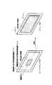
従来、この種の画像メモリを用いる画像データ処理の方法の一例として、特許文献1(特許第2956527号公報)に記載された画像データ処理方法がある。この特許文献1に記載の画像データ処理方法は、画像処理を水平方向処理と、垂直方向処理とに分けて実行するものである。図54を参照して、この特許文献1に記載の画像処理方法を説明する。 Conventionally, as an example of an image data processing method using this type of image memory, there is an image data processing method described in Patent Document 1 (Japanese Patent No. 2956527). The image data processing method described in
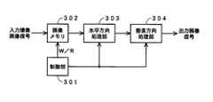
すなわち、図54に示すように、撮像素子からの入力撮像画像データ(A/D変換されたデジタル画像信号であるとする)は、制御部301からの書き込み/読み出し制御信号W/Rによる書き込み制御により、1画面分の撮像画像データが保存可能な容量を有する画像メモリ302に書き込まれる。 That is, as shown in FIG. 54, input captured image data from the image sensor (assuming that it is an A / D converted digital image signal) is written by a write / read control signal W / R from the
そして、この画像メモリ302に書き込まれた撮像画像データは、制御部301からの書き込み/読み出し制御信号W/Rによる読み出し制御により、1垂直周期遅れて読み出されて、水平解像度変換や水平方向手ぶれ補正などの水平方向処理部303に供給される。水平方向処理部303では、水平方向の解像度が指定されたものとなるようにするため、あるいは、水平方向の手ぶれを補正するために、画像データに対して画素間引きや画素補間を行なう。 Then, the captured image data written in the
水平方向処理部303で水平方向処理された撮像画像データは、垂直方向処理部304に供給される。垂直方向処理部304では、垂直方向の解像度が指定されたものとなるようにするため、あるいは、垂直方向の手ぶれを補正するために、画像データに対してライン間引きやライン補間を行なって垂直方向処理を行ない、例えば手ぶれ補正がなされた所望の解像度の出力撮像画像信号を出力する。 The captured image data processed in the horizontal direction by the horizontal
ここで、画像メモリ302の記憶容量は、撮像画像データの1画面分(1垂直周期分)以上の容量とされており、この画像メモリ302には、図55において実線で示すようにして、撮像画像データの書き込みがなされる。そして、図55において破線で示すように、書き込みに対して1垂直周期遅れて、当該書き込まれた撮像画像データが順次に読み出される。 Here, the storage capacity of the
画像メモリ302の記憶容量として、1画面分以上必要であるのは、この例では、1垂直周期遅れて画像データの読み出しが行なわれるためである。すなわち、画像メモリ302の画像データは、1垂直周期経過すると、次の垂直周期分の画像データにより上書きされてしまうので、それを回避するべく、画像データの読み出しが行なわれる前に、次の1画面分の画像データにより前の画像データが上書きされてしまわないようにするため、記憶容量として1画面分を越える分のマージンを必要とするからである。 The storage capacity of the
このようにすることにより、画像メモリ302においては、書き込みに対して読み出しが追い越すことなく、撮像画像データの書き込みおよび読み出しがなされて、解像度変換処理等が行なわれ、所望の解像度の画像データ等が出力される。 By doing in this way, in the
しかし、この特許文献1の画像データ処理方法では、画像メモリ302としては、撮像素子の最高解像度分の画素数(=水平方向の画素数×ライン数)に対応したメモリ容量が必要となる。例えば、HD(High Definition;高精細度)画像のデータが処理対象であって、当該HD画像データの1フィールド分の輝度信号および色差信号を、8ビット/画素で記憶すると、画像メモリ302として必要な記憶容量は約12Mビットとなる。このため、非常に大容量のメモリが必要になり、画像メモリが大型化すると共に、高価格となる。 However, in the image data processing method disclosed in
また、撮像素子として、より多い画素数のものを用いた場合には、それに対応して、画像メモリ302の記憶容量を大きくする必要があるという問題もある。 In addition, when an image sensor having a larger number of pixels is used, there is a problem that the storage capacity of the
これに対して、図56に示すように、水平方向処理部303を、画像メモリ301の前段に設け、撮像素子からの撮像画像データを、そのまま画像メモリ302に書き込むのではなく、水平方向処理部303により水平解像度変換などの水平方向の画像処理を画像データに施して、水平方向の画像データ量を小さくした後、画像メモリ301に、1画面分の撮像画像データを書き込むようにする方法も考えられる。この場合も、画像メモリ301からは、1垂直周期分遅れたタイミングで画像データが読み出されて、垂直方向処理部304に供給され、垂直解像度変換などの垂直方向の画像処理がなされて、出力画像信号とされる。 On the other hand, as shown in FIG. 56, a horizontal
この図56の例の場合には、画像メモリ302には、水平方向処理部303で水平方向の画像処理を行なって画素数が少なくなった1画面分の画像データが書き込まれることになる。このため、画像メモリ302の記憶容量は、水平方向の画像処理後の1画面分の画像データ量でよいので、図54の例の構成の場合よりも画像メモリ302の記憶容量を少なくすることができる。 In the case of the example of FIG. 56, image data for one screen in which the number of pixels is reduced by performing horizontal image processing in the horizontal
ところで、図56のように、水平方向処理をした画像データを画像メモリに書き込み、当該画像メモリから、垂直方向処理のために画像データを読み出すとき、画像処理内容によって、次のような問題が発生する。 Incidentally, as shown in FIG. 56, when the image data that has been subjected to the horizontal processing is written into the image memory and the image data is read out from the image memory for the vertical processing, the following problems occur depending on the content of the image processing. To do.
図56の構成の垂直方向処理においては、処理結果として得ようとするラインの要求REQを制御部301に対して送る。すると、制御部301は、要求されたラインの画像データを垂直補間などにより得るための複数のラインを計算し、その画像メモリ302上のアドレスを求める。そして、求めたアドレスを用いて、要求されたラインの垂直方向処理に必要な複数ラインのデータを画像メモリ302から読み出すようにする。 56, a request REQ for a line to be obtained as a processing result is sent to the
この場合に、例えば、一般的に、電子手ぶれ補正、電子ズーム、解像度変換などの画像処理においては、図57に示すように、垂直方向処理部304が処理しようとするラインが決まると、当該ラインの垂直方向処理に必要な複数ラインのそれぞれのアドレス(垂直方向アドレス)は、水平方向には変化することはない。 In this case, for example, in general, in image processing such as electronic image stabilization, electronic zoom, and resolution conversion, when a line to be processed by the
したがって、ラインの要求REQが制御部301に到来したとき、制御部301では、1ライン分の画像データの処理に、同じ垂直方向アドレスを指定することにより、画像データの読み出しが可能となる。 Therefore, when the line request REQ arrives at the
ところが、画像処理の中には、ラインの要求REQが制御部301に到来したとき、制御部301では、1ライン分の画像データの読み出し処理の際に、同じ垂直方向アドレスを指定するだけではなく、水平方向の画素位置に応じて垂直方向アドレスを変更しなければならない場合がある。この場合の一例を、次に示す。 However, in the image processing, when a line request REQ arrives at the
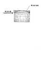
一般に撮像レンズは歪曲収差特性を有しており、このため、撮像画像には、例えば図58に示すような歪みが生じる。高精度で高性能な撮像レンズを用いた場合には、この撮像画像歪みは目立たないが、低価格の撮像レンズを使用する場合や光学ズームレンズを使用する場合には、無視できない程度の画像歪みが生じる。 In general, an imaging lens has a distortion characteristic, and for this reason, distortion as shown in FIG. 58 occurs in a captured image, for example. When using a high-precision and high-performance imaging lens, this captured image distortion is inconspicuous, but when using a low-priced imaging lens or using an optical zoom lens, it cannot be ignored. Occurs.
すなわち、例えば図58(A)に示すような格子縞の被写体を、歪曲収差が大きい撮像レンズを用いて撮像したときには、その撮像画像は、図58(B)に示すように、格子縞を構成する縦横の直線が、湾曲するような画像歪みを生じる。この撮像レンズによる画像歪みは、撮像素子の各画素位置に応じたものであり、かつ、撮像レンズごとに特有のものであり、また、撮像素子に対する撮像レンズの位置が変化すると、その位置に応じたものとなる。 That is, for example, when an object having a checkered pattern as shown in FIG. 58 (A) is imaged using an imaging lens having a large distortion, the captured image has a vertical and horizontal configuration that forms the checkered pattern as shown in FIG. 58 (B). This straight line causes distortion of the image. This image distortion due to the image pickup lens is in accordance with each pixel position of the image pickup device and is specific to each image pickup lens. Also, if the position of the image pickup lens with respect to the image pickup device changes, the image distortion depends on the position. It will be.
このような撮像レンズによる画像歪みを補正する画像処理を行なう場合においても、水平方向の画像歪みと、垂直方向の画像歪みとに分けて、水平方向の画像歪みを水平方向処理部303で補正した後、画像メモリ302に書き込み、垂直方向処理部304からのライン要求REQに応じて、制御部301が、垂直方向処理に必要な複数ラインを計算して、画像メモリ302から読み出すようにすることが考えられる。 Even in the case of performing image processing for correcting image distortion by such an imaging lens, the horizontal image distortion is corrected by the
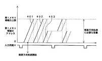
しかし、この場合の1つの要求ラインに対して、垂直方向処理に必要なラインは、図59に示すように、水平方向の画素位置に応じて垂直アドレスを変更するような処理が必要になる。すなわち、垂直処理後に1ラインとなるべき要求ラインの画素データは、図59の左側に示すように、垂直方向処理前の画像においては、垂直方向にずれた位置にある。 However, for one request line in this case, a line necessary for vertical processing needs to be processed so that the vertical address is changed according to the pixel position in the horizontal direction, as shown in FIG. That is, as shown on the left side of FIG. 59, the pixel data of the required line that should become one line after the vertical processing is at a position shifted in the vertical direction in the image before the vertical processing.
垂直方向処理は、要求ラインに対して、その上下複数ラインを用いて補間処理を行なうようにするものであるので、この場合には、垂直方向処理前の画像における要求ラインの画素の上下複数ラインに含まれる画素の垂直方向アドレスは、要求ラインの画素位置の水平方向位置が変化する毎に変化することになる。つまり、垂直方向処理のための画像メモリ302に対する垂直方向アドレスは、1ラインの処理について固定ではなく、水平方向の画素毎にランダムに変化するものとなる。 In the vertical direction processing, interpolation processing is performed using a plurality of upper and lower lines for the requested line. In this case, the upper and lower lines of the pixels of the requested line in the image before the vertical direction processing are used. The vertical address of the pixel included in the pixel changes whenever the horizontal position of the pixel position of the request line changes. That is, the vertical address for the
この結果、撮像レンズによる画像歪みを補正する画像処理の垂直方向処理においては、画像メモリ302からの画像データの読み出しは、水平方向の画素位置に応じて、ランダムなライン位置からの読み出し、つまり、ランダムアクセスが必要となる。 As a result, in the vertical processing of image processing for correcting image distortion caused by the imaging lens, reading of image data from the
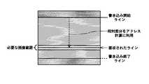
画像メモリ302からの読み出しについて、ランダムアクセスを回避する最も容易な方法は、図60に示すように、処理要求されたラインに注目し、その1ラインについての垂直方向処理で必要とする複数ラインの最上位ラインと最下位ラインを検索し、当該最上位ラインと最下位ラインの間の範囲の複数ラインの全てを読み出す方法である。 As shown in FIG. 60, the easiest method for avoiding random access for reading from the
この方法は、画像メモリから読み出すラインのアドレス計算は容易であるが、垂直方向処理には不必要な画素(図60において塗りを付していない空白により示す)を多数読み出すことになり、その分、消費電力が大きくなるだけでなく、最悪はリアルタイム処理を可能とするために、クロック周波数を高くしなければならなくおそれがある。 This method makes it easy to calculate the address of the line to be read from the image memory, but it reads a large number of pixels (indicated by unfilled blanks in FIG. 60) that are unnecessary for vertical processing. Not only does the power consumption increase, but in the worst case, the clock frequency may have to be increased to enable real-time processing.
これに対して、図61に示すように、処理要求されたラインの各画素毎に、垂直方向処理で必要とする複数ラインアドレスを計算し、当該画素毎の複数ラインアドレスにより垂直方向処理に必要な画素データを読み出すようにすれば、垂直方向処理には不必要な画素は一切読み出さないので、図60の場合のような問題は生じない。 On the other hand, as shown in FIG. 61, a plurality of line addresses required for the vertical processing are calculated for each pixel of the line requested to be processed, and are necessary for the vertical processing by the plurality of line addresses for each pixel. If the pixel data is read out, no unnecessary pixels are read out in the vertical direction processing, so the problem as in the case of FIG. 60 does not occur.
しかしながら、図61の方法の場合には、処理要求されたラインの各画素毎に、垂直方向処理で必要とする複数ラインアドレスを計算する必要がある上、その都度、読み出しコマンドを発行する必要があり、やはり消費電力の点で実用的ではない。 However, in the case of the method shown in FIG. 61, it is necessary to calculate a plurality of line addresses required for vertical processing for each pixel of a line requested to be processed, and to issue a read command each time. Yes, it is not practical in terms of power consumption.
以上の点にかんがみ、出願人は、上記の消費電力の問題および処理効率の問題を改善することができる画像データ処理方法および装置を、特許文献2(特開2006−222827号公報)として提供した。 In view of the above points, the applicant has provided, as Patent Document 2 (Japanese Patent Laid-Open No. 2006-222827), an image data processing method and apparatus that can improve the above-described problems of power consumption and processing efficiency. .
この特許文献2の処理方法は、図60のように、処理要求されたラインについての1ライン全体について垂直方向処理で必要とする複数ラインの最上位ラインと最下位ラインを検索するのではなく、1ライン分の有効画素数の1/N(Nは2以上の正の整数)からなる水平方向の複数画素単位で、処理要求されたラインについて垂直方向処理で必要とする複数ラインの最上位ラインと最下位ラインとを検索する。 As shown in FIG. 60, the processing method disclosed in
図62に、例えば水平方向の8画素単位で、処理要求されたラインについて垂直方向処理で必要とする複数ラインの最上位ラインと最下位ラインとを検索した場合の例を示す。 FIG. 62 shows an example in which the highest line and the lowest line of a plurality of lines required in the vertical direction processing are searched for the requested line in units of 8 pixels in the horizontal direction, for example.
この特許文献2の方法によれば、画像メモリ領域に対する画像データの書き込みおよび読み出しは、複数画素単位であるので、上述の図60の方法のように複数ライン分を読み出す場合に比べて、画像メモリ領域から読み出される垂直方向処理に不必要な画素の数を少なくすることができ、処理効率が向上する。 According to the method of
すなわち、水平8画素内の垂直方向の歪みの変動をチェックした後、そのアクセス範囲を決定することで、垂直方向のメモリアクセスは、水平8画素内で最低限必要な範囲だけのアクセスが可能となり、不必要なデータの読み出しは削減できる。図60の場合と比べると、図62に示すように、不必要なデータの読み出しは削減できていることがわかる。 In other words, by checking the vertical distortion variation in the horizontal 8 pixels and determining the access range, the memory access in the vertical direction can be accessed only within the minimum necessary range in the horizontal 8 pixels. Unnecessary data reading can be reduced. Compared to the case of FIG. 60, as shown in FIG. 62, it can be seen that unnecessary reading of data can be reduced.
また、特許文献2の方法においては、画像メモリに対する画像データの読み出しは、複数画素単位例えば8画素単位で行なうようにしているので、読み出しコマンドの発行回数は当該複数画素単位となり、上述の図61の方法のように画素単位にコマンドを発生する場合に比べて少なくなり、低消費電力化することができる。 In the method of
以上のことから、先に提供した特許文献2の手法によれば、図60の場合および図61の場合に存在する問題を解決して、低消費電力化と、高処理効率化を実現することができる。 From the above, according to the technique of
上記の特許文献および非特許文献は、次の通りである。
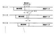
ところで、上述の図56の処理構成において、画像メモリ302を、水平方向処理部303の処理結果を格納する第1メモリ領域と、第2メモリ領域に分け、それらの第1メモリ領域と第2メモリ領域に対する書き込みアクセスおよび読み出しアクセスを詳細に示すと、図63に示すように表すことができる。 In the processing configuration of FIG. 56 described above, the
すなわち、水平方向処理部303の水平方向処理結果の画像データを画像メモリ302の第1メモリ領域3021に書き込む処理は書き込みアクセスW1、この第1メモリ領域3021から、前記水平方向処理結果の画像データを読み出して垂直方向処理部304に供給する処理は読み出しアクセスR1、垂直方向処理部304の垂直方向処理結果の画像データを画像メモリ302の第2メモリ領域3022に書き込む処理は書き込みアクセスW2、この第2メモリ領域3022から、前記垂直方向処理結果の画像データを読み出して出力画像データとする処理は読み出しアクセスR2とすることができる。 That is, the process of writing the image data of the horizontal direction processing result of the horizontal
そして、例えば動作撮像データの記録時や再生時のように、入力撮像画像データを、前記水平方向処理および前記垂直方向処理をして、出力画像データを得るまでの処理を、リアルタイム処理する必要がある場合には、上述の4つのアクセスW1,W2,R1,R2を、特許文献2の場合には、アクセス単位である水平方向の8画素単位で行う必要がある。 And, for example, during the recording or reproduction of motion imaging data, it is necessary to perform real-time processing until input image data is subjected to the horizontal direction processing and the vertical direction processing to obtain output image data. In some cases, the above-described four accesses W1, W2, R1, and R2 need to be performed in units of eight pixels in the horizontal direction, which is an access unit, in the case of
特許文献2では、1画素当たりを1メモリアクセスサイクル(以下、メモリアクセスサイクルを単にサイクルという)とし、したがって、書き込み/読み出しの単位である水平方向の8画素単位では8サイクルを1処理単位周期とする。そして、1処理単位周期内に前記4つのアクセスW1,W2,R1,R2を1サイクル単位で割り当てて、それぞれのアクセスW1,W2,R1,R2を当該割り当てられたサイクルにおいて実行することとする。 In
この場合に、4つのアクセスW1,W2,R1,R2のうち、読み出しアクセスR1は、前述したように、水平方向の8画素のみを読み出すのではなく、各画素について垂直方向の8画素も読み出す必要があるので、1サイクルでは不足する。一方、その他の3つのアクセスW1,W2,R2は、それぞれ1サイクルを割り当てることで、そのアクセスを実行することができる。 In this case, out of the four accesses W1, W2, R1, and R2, the read access R1 does not read out only 8 pixels in the horizontal direction as described above, but also needs to read 8 pixels in the vertical direction for each pixel. Therefore, one cycle is insufficient. On the other hand, the other three accesses W1, W2, and R2 can be executed by allocating one cycle respectively.
そこで、特許文献2においては、図64に示すように、1処理単位周期の8サイクルのうちの3サイクルは、アクセスW1,W2,R2にそれぞれ1サイクルずつ割り当て、読み出しサイクルR1には、最高で5サイクルを割り当てることができるようにしている。 Therefore, in
そして、画像メモリ302は、4バンクの構成として、制御部301が、それぞれのバンクにライン単位で画像データの書き込みおよび読み出しができるようにすると共に、読み出しサイクルR1においては、4バンクから同時に4ラインを読み出すことができるようにしている。 The
このように、制御部301による垂直方向処理用の画像データの読み出しアクセスR1には、1処理単位周期区間で、最大5回のアクセス権を与えているおり、画像メモリ302は4バンク構成で4ラインを同時に読み出すことができるので、
4ライン×5回=20ライン
分のデータを、1処理単位周期区間で取得可能となる。As described above, the access right R1 of the image data for vertical processing by the
Data for 4 lines × 5 times = 20 lines can be acquired in one processing unit cycle section.
このため、1処理単位周期区間、すなわち、8サイクル内(リアルタイム処理可能な範囲内)では、図65に示すように、垂直方向の画像歪みが、水平方向の8画素単位で、変動12(垂直方向に12画素の変動)までの歪みの「変動」の範囲内であれば、リアルタイム処理対応可能となる。 For this reason, in one processing unit cycle section, that is, within 8 cycles (within a range in which real-time processing is possible), as shown in FIG. 65, the vertical image distortion varies in units of 8 pixels in the horizontal direction (vertical 12). If it is within the range of “variation” of distortion up to 12 pixels in the direction), real-time processing is possible.
つまり、この実施形態の撮像装置では、水平8画素内での垂直方向の変動が12であるならば、その補正処理をリアルタイム処理可能となる。なお、図65において、スロット1〜5のそれぞれは、それぞれ1回のアクセスを示している。 That is, in the imaging apparatus of this embodiment, if the vertical variation within the horizontal 8 pixels is 12, the correction process can be performed in real time. In FIG. 65, each of the
以上のように、レンズ歪みが所定値以下、上述の例の場合には変動12以内の変動である場合には、高画質な画像歪み補正と解像度変換とが実現できる。一般のデジタルカメラやデジタルビデオカメラに使用されているレンズの場合には、画像歪みによる変動は変動12以内であるので、これで十分に対応可能である。 As described above, when the lens distortion is equal to or less than a predetermined value and within the
しかしながら、例えば、自動車の後方に撮像装置を付けて、その撮像画像を車庫入れの際に参照するようにする場合などにおいては、魚眼レンズなどの超広角レンズが使用されるようになっている。この魚眼レンズのような特殊レンズを使用する場合には、垂直方向の画像歪みの変動が12画素を超えることが生じるので、1処理単位周期区間周期では、水平方向の8画素単位で必要とする複数ラインからの画像データを読み出すことができなくなるという問題がある。 However, for example, when an imaging device is attached to the rear of an automobile and the captured image is referred to when entering the garage, an ultra-wide-angle lens such as a fisheye lens is used. When a special lens such as this fisheye lens is used, the fluctuation in image distortion in the vertical direction may exceed 12 pixels. Therefore, in one processing unit cycle interval period, a plurality of pixels required in the horizontal direction of 8 pixels are required. There is a problem that image data from the line cannot be read.
この発明は、このように画像メモリに対して要求されたアクセスが、1処理単位周期区間内でできなくなったときにも、当該アクセスを完了することができるようにすることを目的とする。 An object of the present invention is to make it possible to complete the access even when the requested access to the image memory cannot be performed within one processing unit cycle section.
上記の課題を解決するために、請求項1の発明は、
画像データを格納する画像メモリと、
前記画像メモリに書き込む画像データを出力する、または、前記画像メモリから読み出した画像データを受けて所定の処理を行う複数個の処理手段と、
前記複数個の処理手段からの書き込みまたは読み出しの要求を受けて、前記画像メモリに対する画像データの書き込みアクセスまたは画像データの読み出しアクセスを制御するメモリ制御手段と、
を備え、
前記メモリ制御手段は、
前記画像メモリに対して、1ライン分の有効画素数の1/N(Nは2以上の正の整数)からなる水平方向の複数画素単位で、前記書き込みアクセスの1サイクルまたは前記読み出しアクセスの1サイクルを行なうと共に、
複数サイクルを処理単位周期として、前記複数個の処理手段のそれぞれからの前記要求に応じた書き込みまたは読み出しのアクセス処理を、前記処理単位周期内に1サイクル単位ですべて割り当てて実行し、かつ、前記処理単位周期を繰り返すようにするものであり、
さらに、前記メモリ制御手段は、
前記処理単位周期の1周期内に割り当てられた前記処理手段のそれぞれに対応して割り当てられた前記サイクル内で、それぞれの前記処理手段からの前記要求に基づいて指定された前記アクセス処理が完了できるか否かを判別する判別手段と、
前記判別手段で前記アクセス処理が完了できないと判別したときに、前記要求を出した前記処理手段に対して、前記処理単位周期の待機指示信号を送って、新たな前記要求の送出を一時停止させるようにすると共に、前記処理単位周期の1周期内でできないとされた前記アクセス処理を、当該アクセス処理を行うべき前記処理単位周期に続く1または複数の処理単位周期において前記処理手段に対応して割り当てた前記サイクルにおいても実行するようにするアクセス実行手段と、
を備えることを特徴とする画像データ処理装置を提供することを特徴とする。In order to solve the above problems, the invention of
An image memory for storing image data;
A plurality of processing means for outputting image data to be written to the image memory, or receiving image data read from the image memory and performing predetermined processing;
Memory control means for receiving a write or read request from the plurality of processing means and controlling image data write access or image data read access to the image memory;
With
The memory control means includes
One cycle of the write access or 1 of the read access in units of a plurality of pixels in the horizontal direction consisting of 1 / N (N is a positive integer of 2 or more) of the number of effective pixels for one line with respect to the image memory. While doing the cycle,
A plurality of cycles as a processing unit period, and a write or read access process corresponding to the request from each of the plurality of processing units is allotted and executed in units of one cycle within the processing unit period, and The processing unit cycle is repeated,
Further, the memory control means includes
The access processing specified based on the request from each processing means can be completed within the cycle assigned corresponding to each of the processing means assigned within one cycle of the processing unit cycle. Determination means for determining whether or not,
When the determining means determines that the access processing cannot be completed, a waiting instruction signal for the processing unit period is sent to the processing means that has issued the request to temporarily stop sending the new request In addition, the access processing that has been determined to be impossible within one cycle of the processing unit cycle corresponds to the processing means in one or more processing unit cycles following the processing unit cycle in which the access processing is to be performed. Access executing means for executing in the assigned cycle;
An image data processing apparatus characterized by comprising: is provided.
上述の構成の請求項1の発明においては、判別手段で、処理手段のそれぞれに対応して割り当てられたサイクル内で、それぞれの処理手段からの要求に基づいて指定されたアクセス処理が完了できるか否かが判別される。 In the invention of
そして、アクセス実行手段は、判別手段でアクセス処理が完了できないと判別したときに、要求を出した処理手段に対して、処理単位周期の待機指示信号を送って、新たな要求の送出を一時停止させるようにすると共に、処理単位周期の1周期内でできないとされたアクセス処理を、当該アクセス処理を行うべき処理単位周期に続く1または複数の処理単位周期において前記処理手段に対応して割り当てたサイクルにおいても実行するようにする。 Then, when the access execution means determines that the access processing cannot be completed by the determination means, it sends a wait instruction signal for the processing unit cycle to the processing means that issued the request, and temporarily stops sending a new request. In addition, the access processing that is determined to be impossible within one processing unit cycle is assigned corresponding to the processing means in one or more processing unit cycles following the processing unit cycle in which the access processing is to be performed. Execute in the cycle.
これにより、処理手段からの要求に応じた処理ができなくなることが無くなり、前述した課題を解決することができる。 As a result, the processing according to the request from the processing means can be prevented, and the above-described problems can be solved.
この発明によれば、画像メモリに対するアクセスを、1処理単位周期区間内でできなくなったときにも、当該アクセスの処理を完了することができる。 According to the present invention, even when access to the image memory cannot be performed within one processing unit cycle section, the access processing can be completed.
[この発明の実施形態]
以下に説明するこの発明による画像データ処理装置の実施形態は、撮像素子としてX−Yアドレス型の固体撮像素子の代表例であるCMOS(Complementary Metal−Oxide Semiconductor)イメージャ(CMOS型の固体撮像素子)を用いる撮像装置の場合の例である。そして、この撮像装置において、画像処理として、撮像した撮像画像について、手ぶれによる撮像画像歪みと、撮像レンズの歪曲収差特性による撮像画像歪みとを、併せて補正すると共に、電子ズーム処理および所望の解像度の出力画像データを得る解像度変換処理を行なうことができる場合である。[Embodiment of the Invention]
An embodiment of an image data processing apparatus according to the present invention described below is a CMOS (Complementary Metal-Oxide Semiconductor) imager (CMOS solid-state image sensor) that is a representative example of an XY address type solid-state image sensor as an image sensor. It is an example in the case of the imaging device using this. In this imaging apparatus, as image processing, the captured image that has been captured is corrected together with the captured image distortion due to camera shake and the captured image distortion due to the distortion aberration characteristic of the imaging lens, as well as electronic zoom processing and a desired resolution. This is a case where resolution conversion processing for obtaining the output image data can be performed.
なお、この実施形態の撮像装置は、動画像および静止画像の両方を撮像可能であり、動画像の撮像画像データを処理する場合と、静止画像の撮像画像データを処理する場合の、何れの場合にも、上述の画像処理を適用することができるものである。 Note that the imaging apparatus of this embodiment can capture both moving images and still images, and in either case of processing moving image captured image data or processing still image captured image data In addition, the above-described image processing can be applied.
この発明の実施の形態の撮像装置を説明する前に、CMOSイメージャなどのX−Yアドレス型の固体撮像素子に特有の手ぶれによる画像ひずみについて説明する。 Before describing the image pickup apparatus according to the embodiment of the present invention, image distortion caused by camera shake, which is peculiar to an XY address type solid-state image pickup device such as a CMOS imager, will be described.
例えば従来一般的に用いられているCCD(Charge Coupled Device)を用いた固体撮像素子(以下、CCDを用いた固定撮像素子をCCDイメージャという)の場合には、全画素を同時期に露光し、1フレーム(または1フィールド。以下同じ)の画像データについては、データ取り出しタイミングが全く同一であるので、手ぶれ変位量としては、図2において矢印で示すように、1フレーム分の全画素について、1つの手ぶれ変位量Vcsを考えればよい。 For example, in the case of a solid-state imaging device using a CCD (Charge Coupled Device) generally used in the past (hereinafter, a fixed imaging device using a CCD is called a CCD imager), all pixels are exposed at the same time, For image data of one frame (or one field, the same applies hereinafter), the data extraction timing is exactly the same, so the amount of camera shake displacement is 1 for all pixels for one frame, as shown by the arrows in FIG. One camera shake displacement amount Vcs may be considered.
つまり、図2において、本来、被写体は実線で示す領域FLaに蓄積されるものであったのに、手ぶれにより点線で示す領域FLbに移動した場合には、当該フレームで1つの手ぶれ変位量Vcsを検出し、当該手ぶれ変位量Vcs分だけ、読み出し画素位置(サンプリング画素位置)を補正することにより、手ぶれに起因する撮像画像歪を補正することができる。 That is, in FIG. 2, when the subject is originally accumulated in the area FLa indicated by the solid line but moved to the area FLb indicated by the dotted line due to the camera shake, the one camera shake displacement amount Vcs is reduced in the frame. By detecting and correcting the readout pixel position (sampling pixel position) by the camera shake displacement amount Vcs, it is possible to correct the captured image distortion caused by the camera shake.
なお、図2に示すように、一般に、撮像素子では、その全画素を有効画素として扱うのではなく、全画素からなる領域(以下、実効画像領域という)AFLのうちの、周辺の領域を除く、水平有効領域および垂直有効領域で定まる中央部を有効画像領域EFLとして用いているものが多い。 As shown in FIG. 2, in general, an imaging device does not treat all the pixels as effective pixels, but excludes a peripheral region in an area AFL composed of all pixels (hereinafter referred to as an effective image area). In many cases, the central portion defined by the horizontal effective area and the vertical effective area is used as the effective image area EFL.
このようなイメージャを用いた場合、手ぶれ補正により読み出し画素位置が変化しても、手ぶれ量が、実効画像領域AFLと有効画像領域EFLとの差分よりも小さい範囲では、イメージャが元々有している画素のデータを用いて歪み補正をすることができるので、補間処理などにより、手ぶれ補正に必要なデータを生成する場合に比べて、画像の劣化は少なくなる。 When such an imager is used, even if the readout pixel position changes due to camera shake correction, the imager originally has an amount of camera shake within a range smaller than the difference between the effective image area AFL and the effective image area EFL. Since distortion correction can be performed using pixel data, image degradation is reduced as compared to the case where data necessary for camera shake correction is generated by interpolation processing or the like.
これに対して、CMOS型イメージャのようなX−Yアドレス型の固体撮像素子の場合には、画面の水平方向(X方向)の位置と、垂直方向(Y方向)位置とを指定することにより、画素単位で撮像データを読み出すことが可能である。ただし、CMOSイメージャなどのX−Yアドレス型の固体撮像素子においては、実用上は、1水平ライン分の画素群単位で読み出し(サンプリング)して、撮像画像データを出力するものが一般的である。 On the other hand, in the case of an XY address type solid-state imaging device such as a CMOS type imager, by specifying the position in the horizontal direction (X direction) and the position in the vertical direction (Y direction) of the screen. The imaging data can be read out in units of pixels. However, an XY address type solid-state imaging device such as a CMOS imager generally reads (samples) and outputs captured image data in units of pixels for one horizontal line. .
このように、CMOSイメージャから撮像データを水平ライン単位で読み出す場合には、図3に示すように、各水平ラインのついての露光期間は、水平ライン単位の読み出し時間差に応じたΔtだけ、時間的なずれを生じる。なお、1画素単位で撮像画像データの読み出しがなされる場合であっても、ライン間の読み出し時間差に比べて、画素間の読み出し時間差は無視できるほど小さい。そこで、1画素単位で撮像画像データの読み出しがなされる場合であっても、同様な露光期間の時間的なずれを生じるものとすることができる。 As described above, when the imaging data is read out from the CMOS imager in units of horizontal lines, as shown in FIG. 3, the exposure period for each horizontal line is timed by Δt corresponding to the reading time difference in units of horizontal lines. A gap occurs. Even when the captured image data is read out in units of pixels, the difference in readout time between pixels is so small that it is negligible compared to the difference in readout time between lines. Therefore, even when the captured image data is read out in units of pixels, a similar time lag of the exposure period can be generated.
このため、CMOSイメージャを用いた撮像装置により、例えば走る電車の中から外の景色を撮影すると、本来は図4(A)のような画像が得られるべきものであるのに、図4(B)に示すように、本来鉛直に立っている家や木が傾いた画像が出力撮像画像となってしまう。これがCMOSイメージャ特有のフォーカルプレーン現象である。 For this reason, when an outside landscape is photographed from a running train, for example, with an imaging device using a CMOS imager, an image as shown in FIG. 4A should be obtained, but FIG. ), An image in which a house or tree originally standing vertically is inclined becomes an output captured image. This is the focal plane phenomenon unique to CMOS imagers.
図4(B)の画像例は、水平方向に移動しながら撮影したものであるため、被写体が傾いて撮像されるが、例えば垂直方向に移動しながら撮影した場合には、図示は省略するが、被写体が垂直方向に縮んだり、伸びたりするような画像となる。 Since the image example in FIG. 4B is taken while moving in the horizontal direction, the subject is imaged while being tilted. For example, when the image is taken while moving in the vertical direction, the illustration is omitted. The image is such that the subject contracts or expands in the vertical direction.
この現象が発現するのは、CMOSイメージャを使用する撮像装置を持つ撮影者が高速に移動しながら撮影したり、逆に、固定位置にいる撮影者が高速に移動する被写体を撮影したりした場合であり、撮像装置と被写体の相対速度が速い場合に顕著となる。ただし、一般的な撮影において、このような状況は稀であるといえる。 This phenomenon appears when a photographer with an imaging device using a CMOS imager takes a picture while moving at high speed, or conversely, a photographer at a fixed position takes a picture of a fast moving subject. This is remarkable when the relative speed between the imaging device and the subject is high. However, it can be said that such a situation is rare in general photography.
しかしながら、撮影者が撮像装置を手で持って撮影している場合に、撮像装置を持っている撮影者の手が、微小かつ高速に振動した場合、すなわち、手ぶれが発生した場合、上述したフォーカルプレーン現象が発現することになる。 However, when the photographer is shooting with the imaging device held by hand, when the photographer's hand holding the imaging device vibrates minutely and at high speed, that is, when camera shake occurs, the above-described focal A plain phenomenon will appear.
なぜなら、CMOSイメージャの場合の手ぶれ(以下、CMOS手ぶれという)の値は、CCDイメージャのように1フレーム内で1個の値ではなく、前述したように、1フレーム内における画素やライン毎のサンプリング時刻の違いにより、画素や水平ラインごとに異なるものとなる。このため、CMOSイメージャを用いた撮像装置においては、単に、1フレーム単位での手ぶれ量を用いた補正を行っても、前述したフォーカルプレーン現象による歪みは、補正されずに残ってしまう。 This is because the value of camera shake (hereinafter referred to as CMOS camera shake) in the case of a CMOS imager is not a single value in one frame as in a CCD imager, but sampling for each pixel or line in one frame as described above. Due to the difference in time, it differs for each pixel and horizontal line. For this reason, in an imaging apparatus using a CMOS imager, the distortion caused by the focal plane phenomenon described above remains uncorrected even if correction is performed using the amount of camera shake per frame.
この際、手ぶれの方向、大きさ、速度が、1フレーム内(1枚の撮像画像内)で一律でないことが原因となって、CMOSイメージャを用いた撮像装置で、CMOS手ぶれが生じた時の被写体の撮像画像出力は、図4(C)に示すように、グニャグニャした奇妙な画像歪みが生じたものとなる。 At this time, due to the fact that the direction, size, and speed of camera shake are not uniform within one frame (within one captured image), an image pickup device using a CMOS imager has a camera shake when a CMOS camera shake occurs. As shown in FIG. 4C, the output of the captured image of the subject is the one in which strange and distorted image distortion has occurred.
そこで、この実施の形態では、1水平ライン単位で撮像画像データがCMOSイメージャから読み出されるとき、各水平ラインについての手ぶれによる位置変位量(以下、手ぶれ量という)を検出し、当該検出した手ぶれ量分だけ、発生した手ぶれとは逆方向にずれた位置から当該水平ラインのデータを読み出すように補正するものである。 Therefore, in this embodiment, when the captured image data is read from the CMOS imager in units of one horizontal line, a positional displacement amount due to camera shake (hereinafter referred to as camera shake amount) for each horizontal line is detected, and the detected camera shake amount is detected. Accordingly, correction is performed so that the data of the horizontal line is read from a position shifted in the opposite direction to the generated camera shake.
しかし、手ぶれ量を各水平ラインについて得ることは、手ぶれを検出するセンサのサンプリング周波数などの条件から困難であることに鑑み、この実施形態においては、画面の垂直方向の複数ライン分置きの位置での手ぶれ量を、離散的に検出する。そして、手ぶれ検出を行なうライン以外の、手ぶれ量を直接的には検出しないラインに対する手ぶれ量は、検出された手ぶれ量を用いるようにする。 However, in view of the fact that it is difficult to obtain the amount of camera shake for each horizontal line due to conditions such as the sampling frequency of a sensor that detects camera shake, in this embodiment, at the positions of every other line in the vertical direction of the screen. The amount of camera shake is detected discretely. The detected amount of camera shake is used as the amount of camera shake for lines that do not directly detect the amount of camera shake other than the line that detects camera shake.
先ず、図5を用いて、この発明による撮像画像信号の歪み補正方法の実施形態における手ぶれなどによる撮像素子の位置的変化に基づくフォーカルプレーン現象を含む撮像画像歪みの補正処理の概要を説明する。 First, with reference to FIG. 5, an outline of a correction process for a captured image distortion including a focal plane phenomenon based on a positional change of the image sensor due to camera shake or the like in the embodiment of the distortion correction method for a captured image signal according to the present invention will be described.
図5の概要説明図においては、図5(A)に示すように、画像に生じるCMOS手ぶれによる歪みを判りやすく示すために、歪みの無いオリジナルの画像として多数個の長方形からなる格子縞模様の画像を想定している。したがって、CMOS手ぶれによる画像歪みは、当該格子縞模様を構成する長方形の変形歪みとして現れるものとなる。 In the schematic explanatory diagram of FIG. 5, as shown in FIG. 5A, an image having a checkered pattern composed of a large number of rectangles as an original image without distortion is shown in order to easily show distortion caused by CMOS camera shake occurring in the image. Is assumed. Therefore, the image distortion due to the CMOS camera shake appears as a deformation distortion of the rectangle constituting the checkered pattern.
なお、この実施形態においても、CMOSイメージャは、図2に示したような1画面とする水平有効領域および垂直有効領域で定まる有効画像領域EFL(1垂直周期分)よりも広い範囲の実効画像領域AFLを有するものが用いられるものである。なお、図5(A)〜(D)に示した1画面分の画像は、図2の有効画像領域EFLの大きさの画像である。 Also in this embodiment, the CMOS imager has an effective image area in a wider range than an effective image area EFL (one vertical period) determined by a horizontal effective area and a vertical effective area as one screen as shown in FIG. Those having AFL are used. Note that the image for one screen shown in FIGS. 5A to 5D is an image having the size of the effective image area EFL in FIG.
この実施形態では、水平方向の画素クロックの速度は、手ぶれの速度よりも十分に早いとし、また、撮像画像データの読み出しは、1水平ライン単位で順次に行なうものとして、手ぶれ補正は、1水平ライン単位で行なうようにする。 In this embodiment, it is assumed that the speed of the pixel clock in the horizontal direction is sufficiently faster than the speed of camera shake, and that readout of captured image data is sequentially performed in units of one horizontal line, and camera shake correction is performed in one horizontal direction. Do this in line units.
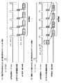
また、この実施形態では、図5(B),(C),(D)に示すように、CMOSイメージャの有効画像領域EFL分の画像区間は、垂直方向に複数に等分割し、各分割画像区間Pdivでは、同じ手ぶれ速度の手ぶれ変位を受けるものと仮定している。ここで、分割数は、手ぶれ補正したときに、必要十分な補正効果が得られる分割画像区間Pdivの大きさを考慮して定められる。以下に説明する例では、有効画像領域EFLの画像区間を垂直方向に8分割するようにする。すなわち、この例では、分割画像区間Pdivは、垂直同期信号の1周期を1/8に分割した区間となる。 In this embodiment, as shown in FIGS. 5B, 5C, and 5D, the image section for the effective image area EFL of the CMOS imager is equally divided into a plurality of parts in the vertical direction. In the section Pdiv, it is assumed that camera shake displacement at the same camera shake speed is received. Here, the number of divisions is determined in consideration of the size of the divided image section Pdiv in which a necessary and sufficient correction effect can be obtained when camera shake correction is performed. In the example described below, the image section of the effective image area EFL is divided into eight in the vertical direction. That is, in this example, the divided image section Pdiv is a section obtained by dividing one period of the vertical synchronization signal into 1/8.
1つの分割画像区間Pdivは、複数水平ライン分からなるが、この実施形態では、同じ分割画像区間Pdivに含まれる複数水平ラインは同じ手ぶれ速度の手ぶれ変位を受けるものと仮定して手ぶれ補正処理を行なうものである。 One divided image section Pdiv includes a plurality of horizontal lines. In this embodiment, the camera shake correction process is performed on the assumption that the plurality of horizontal lines included in the same divided image section Pdiv are subjected to camera shake displacement at the same camera shake speed. Is.
そして、この実施形態では、8個の分割画像区間Pdiv_0〜Pdiv_7のそれぞれの先頭の水平ラインに対する手ぶれ速度ベクトルを、図5(B)の左側の矢印に示すようなものとして、手ぶれ速度検出手段により検出する。すなわち、この例では、手ぶれ速度ベクトルは、1画面分の撮像画像について、8箇所において、離散的に検出するようにする。 In this embodiment, the camera shake speed detection unit assumes that the camera shake speed vector for the top horizontal line of each of the eight divided image sections Pdiv_0 to Pdiv_7 is as shown by the arrow on the left side of FIG. To detect. In other words, in this example, the camera shake velocity vector is discretely detected at eight locations for the captured image for one screen.
図5(B)の画像は、手ぶれ速度ベクトルが、各分割画像区間Pdivで、左側の矢印のようなものとした時に生じる手ぶれによる撮像画像の歪みを示している。この実施形態では、この手ぶれによる撮像画像の歪みを、水平方向処理と垂直方向処理とに分けて、それぞれの方向の歪みを別々に補正するようにする。 The image in FIG. 5B shows the distortion of the captured image due to camera shake that occurs when the camera shake velocity vector is as shown by the left arrow in each divided image section Pdiv. In this embodiment, the distortion of the captured image due to this camera shake is divided into horizontal processing and vertical processing, and the distortion in each direction is corrected separately.
補正処理の詳細については後述するが、この実施形態では、先ず、水平方向の歪みについて補正処理を行ない、次いで、垂直方向の歪みについての補正処理を行なう。この場合に、1画面分の撮像画像のすべてのデータについての水平方向の歪み補正処理が完了する前であっても、垂直方向の歪み補正処理が可能になった段階で、垂直方向の歪み補正処理を開始して、水平方向の歪み補正処理と並行して行なうようにすることにより、効率良く歪み補正処理を行なうようにする。 Although details of the correction processing will be described later, in this embodiment, first, correction processing for horizontal distortion is performed, and then correction processing for vertical distortion is performed. In this case, even before the horizontal distortion correction processing for all the data of the captured image for one screen is completed, the vertical distortion correction is performed when the vertical distortion correction processing is possible. By starting the processing and performing it in parallel with the horizontal distortion correction processing, the distortion correction processing is efficiently performed.
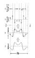
そこで、この実施形態では、先ず、手ぶれによる水平方向の画像歪みを補正するために、図5(C)の左側の矢印および図6の左側の矢印で示すように、各分割画像区間Pdiv_0〜Pdiv_7について検出した手ぶれ速度ベクトルVec(Vec_0〜Vec_7)の水平方向成分の逆符号成分(以下、この手ぶれ速度ベクトルの水平方向成分の逆符号成分を、水平補正速度成分という)X_STB(X_STB_0〜X_STB_7)を求める。 Therefore, in this embodiment, first, in order to correct horizontal image distortion due to camera shake, as shown by the left arrow in FIG. 5C and the left arrow in FIG. 6, the divided image sections Pdiv_0 to Pdiv_7. X_STB (X_STB_0 to X_STB_7) of the reverse direction component of the horizontal direction component of the camera shake velocity vector Vec (Vec_0 to Vec_7) detected with respect to Ask.
そして、各分割画像区間Pdiv_0〜Pdiv_7内においては、各水平ラインのそれぞれについての水平方向の手ぶれ量を補正するための補正量として、上述のようにして求めた水平補正速度成分X_STB_0〜X_STB_7を、それぞれの水平ラインについて時間積分(各分割画像区間Pdiv_0〜Pdiv_7の先頭の水平ライン時点を基準点とした時間で積分)して算出する。図6の右側に、その積分結果の値としての水平方向の手ぶれ補正量(以下、水平手ぶれ補正量という)SX_ADDを示す。 In each of the divided image sections Pdiv_0 to Pdiv_7, the horizontal correction speed components X_STB_0 to X_STB_7 obtained as described above are used as correction amounts for correcting the horizontal camera shake amount for each horizontal line. Each horizontal line is calculated by time integration (integration with the time of the first horizontal line of each divided image section Pdiv_0 to Pdiv_7 as a reference point). On the right side of FIG. 6, a horizontal camera shake correction amount (hereinafter referred to as a horizontal camera shake correction amount) SX_ADD as a value of the integration result is shown.
この図6から判るように、各水平ラインのそれぞれについての水平手ぶれ補正量SX_ADDは、各分割画像区間Pdiv_0〜Pdiv_7においては、一定の傾きで変化し、かつ、積分であるので、分割画像区間の境目では折れ線とはなるが、連続的なものとなり、ずれは生じない。 As can be seen from FIG. 6, the horizontal camera shake correction amount SX_ADD for each horizontal line changes at a constant slope in each divided image section Pdiv_0 to Pdiv_7 and is integral. Although it becomes a broken line at the boundary, it becomes continuous and no deviation occurs.
水平方向の歪み補正処理においては、以上のようにして求められた各ラインについての手ぶれ水平補正量SX_ADDを用いて、CMOSイメージャ上での各水平ラインの水平方向の読み出し開始位置を補正することにより、撮像画像を補正処理する。すなわち、各水平ラインの読み出し開始位置を、図5(B)における手ぶれに応じて水平方向にずれた位置からとすることにより、図5(C)の画像に示すように、水平方向の歪みが補正されることになる。 In the horizontal distortion correction process, the horizontal readout start position of each horizontal line on the CMOS imager is corrected using the camera shake horizontal correction amount SX_ADD for each line obtained as described above. Then, the captured image is corrected. That is, by setting the readout start position of each horizontal line from a position shifted in the horizontal direction in accordance with camera shake in FIG. 5B, the horizontal distortion is caused as shown in the image of FIG. It will be corrected.
この図5(C)の画像は、図5(B)の画像歪みの内の水平方向の歪みは補正されて除去されているが、垂直方向の歪みが残っている。 In the image of FIG. 5C, the horizontal distortion of the image distortion of FIG. 5B is corrected and removed, but the distortion in the vertical direction remains.
そこで、この実施形態では、手ぶれによる垂直方向の画像歪みを補正するため、図5(D)の左側の矢印に示すように、各分割画像区間Pdiv_0〜Pdiv_7について検出した手ぶれ速度ベクトルの垂直方向成分の逆符号成分(以下、この手ぶれ速度ベクトルの垂直方向成分の逆符号成分を、垂直補正速度成分という)Y_STB_0〜Y_STB_7を求める。 Therefore, in this embodiment, in order to correct vertical image distortion due to camera shake, as indicated by the arrow on the left side of FIG. 5D, the vertical component of the camera shake velocity vector detected for each of the divided image sections Pdiv_0 to Pdiv_7. Y_STB_0 to Y_STB_7 (hereinafter, the inverse sign component of the vertical direction component of the camera shake velocity vector is referred to as a vertical correction velocity component).
そして、各分割画像区間Pdiv_0〜Pdiv_7内においては、各水平ラインのそれぞれについての垂直方向の手ぶれ量を補正するための補正量として、上述のようにして求めた垂直補正速度成分Y_STB_0〜Y_STB_7を、それぞれの水平ラインについて時間積分(各分割画像区間Pdiv_0〜Pdiv_7の先頭の水平ライン時点を基準点とした時間で積分)して算出する。 In each of the divided image sections Pdiv_0 to Pdiv_7, the vertical correction speed components Y_STB_0 to Y_STB_7 obtained as described above are used as correction amounts for correcting the amount of vertical camera shake for each horizontal line. Each horizontal line is calculated by time integration (integration with the time of the first horizontal line of each divided image section Pdiv_0 to Pdiv_7 as a reference point).
この積分結果としての垂直方向の手ぶれ補正量(以下、垂直手ぶれ補正量という)SY_ADDは、ここでは、図示を省略するが、各分割画像区間Pdiv_0〜Pdiv_7においては、一定の傾きで変化し、かつ、積分であるので、分割画像区間の境目では折れ線とはなるが、連続的なものとなり、ずれは生じない。 The vertical camera shake correction amount SY_ADD (hereinafter referred to as vertical camera shake correction amount) SY_ADD as an integration result is omitted here, but changes with a constant inclination in each of the divided image sections Pdiv_0 to Pdiv_7, and Since it is integral, it becomes a broken line at the boundary of the divided image section, but it becomes continuous and no deviation occurs.
垂直方向の歪み補正処理においては、以上のようにして求められた各ラインについての垂直手ぶれ補正量SY_ADDを用いて、CMOSイメージャ上での各水平ラインの垂直方向の読み出し開始位置を補正することにより、撮像画像を補正処理する。これにより、図5(D)の画像に示すように、水平方向の場合と同様にして垂直方向の歪みが補正され、歪みの除去された撮像画像データ出力が得られる。 In the vertical distortion correction processing, by using the vertical camera shake correction amount SY_ADD for each line obtained as described above, the vertical readout start position of each horizontal line on the CMOS imager is corrected. Then, the captured image is corrected. Thereby, as shown in the image of FIG. 5D, the distortion in the vertical direction is corrected in the same manner as in the horizontal direction, and the captured image data output from which the distortion is removed is obtained.
なお、上述の説明では、手ぶれ速度ベクトルから水平成分および垂直成分を抽出するときに、その逆符号成分を算出して、補正速度成分とするようにしたが、速度成分あるいは手ぶれ量を逆符号として、補正速度成分あるいは手ぶれ補正量とするのは、撮像画像データに対する手ぶれ補正処理の実行開始前であれば、どの時点であっても良い。 In the above description, when the horizontal component and the vertical component are extracted from the camera shake velocity vector, the opposite sign component is calculated and used as the corrected velocity component. However, the velocity component or the amount of camera shake is used as the opposite sign. The correction speed component or the camera shake correction amount may be set at any time as long as the camera shake correction process for the captured image data is not started.
次に、撮像レンズの歪曲収差特性による撮像画像歪みの補正について説明する。 Next, correction of captured image distortion due to distortion aberration characteristics of the imaging lens will be described.
前述したように、一般に撮像レンズは歪曲収差特性を有しており、このため、例えば図58(A)に示すような格子縞の被写体を、歪曲収差が大きい撮像レンズを用いて撮像したときには、その撮像画像は、図58(B)に示すように、格子縞を構成する縦横の直線が、湾曲するような画像歪みを生じる。この撮像レンズによる画像歪みは、撮像素子の各画素位置に応じたものであり、かつ、撮像レンズごとに特有のものであり、また、撮像素子に対する撮像レンズの位置が変化すると、その位置に応じたものとなる。 As described above, the imaging lens generally has distortion characteristics. For this reason, for example, when an object having a lattice pattern as shown in FIG. As shown in FIG. 58B, the captured image causes image distortion such that the vertical and horizontal straight lines forming the checkered pattern are curved. This image distortion due to the image pickup lens is in accordance with each pixel position of the image pickup device and is specific to each image pickup lens. Also, if the position of the image pickup lens with respect to the image pickup device changes, the image distortion depends on the position. It will be.
したがって、CMOSイメージャのようなX−Yアドレス型の撮像素子を用いて撮像する装置においては、手ぶれによる画像歪みを補正しただけでは、撮像レンズの歪曲収差特性に基づく画像歪みが残ってしまう。 Therefore, in an apparatus for imaging using an XY address type imaging device such as a CMOS imager, image distortion based on the distortion aberration characteristic of the imaging lens remains only by correcting the image distortion due to camera shake.
そこで、この実施形態では、X−Yアドレス型の撮像素子を用いた撮像装置において、手ぶれ等が原因で生じる撮像画像の歪みと共に、撮像レンズの歪曲収差特性に基づく画像歪みを併せて軽減するようにしている。 Therefore, in this embodiment, in an imaging apparatus using an XY address type imaging device, image distortion based on distortion aberration characteristics of an imaging lens is reduced together with distortion of a captured image caused by camera shake or the like. I have to.
この実施形態では、水平手ぶれ補正量および垂直手ぶれ補正量に、撮像レンズの歪曲収差特性に基づく画像歪み(以下、レンズ歪みという)の補正量を加算し、その加算した補正量により撮像画像データを補正処理することにより、手ぶれによる画像歪みと撮像レンズによる画像歪みの両方を同時に補正するようにするものである。 In this embodiment, a correction amount of image distortion (hereinafter referred to as lens distortion) based on the distortion aberration characteristic of the imaging lens is added to the horizontal camera shake correction amount and the vertical camera shake correction amount, and the captured image data is converted by the added correction amount. By performing correction processing, both image distortion caused by camera shake and image distortion caused by the imaging lens are corrected simultaneously.
この実施形態では、以上のように、手ぶれ補正を水平処理と垂直処理に分けるのに合わせて、レンズ歪みの補正も水平処理と垂直処理に分けるようにする。前述もしたように、レンズ歪みは、撮像レンズに固有のものである。そこで、撮像素子上における各画素位置におけるレンズ歪みの補正量は、予め用意することができる。 In this embodiment, as described above, the correction of lens distortion is divided into horizontal processing and vertical processing in accordance with the division of camera shake correction into horizontal processing and vertical processing. As described above, lens distortion is inherent to the imaging lens. Therefore, a correction amount of lens distortion at each pixel position on the image sensor can be prepared in advance.
この実施形態では、撮像素子上における各画素位置におけるレンズ歪みの補正量は、各画素位置に対する補正ベクトルとしてエンコードされて、撮像装置に設けられる補正量デコード部に与えられる。補正量デコード部は、各画素位置の座標(撮像素子上における絶対座標)を引数として、当該画素位置における前記補正ベクトルを得ると共に、その補正ベクトルをデコードして、当該画素位置におけるレンズ歪みの補正量の水平方向補正成分と垂直方向補正成分とを得る。 In this embodiment, the correction amount of the lens distortion at each pixel position on the image sensor is encoded as a correction vector for each pixel position, and is provided to a correction amount decoding unit provided in the imaging apparatus. The correction amount decoding unit obtains the correction vector at the pixel position using the coordinates of each pixel position (absolute coordinates on the image sensor) as an argument, and decodes the correction vector to correct the lens distortion at the pixel position. A quantity of horizontal and vertical correction components is obtained.
そして、撮像素子からの撮像画像データの各水平ラインの画素データは、上述のようにして求められた水平手ぶれ補正量SX_ADDにより、水平方向に手ぶれ速度の水平方向成分に応じた分だけシフトされた座標位置のものとされるが、当該座標位置(画素位置)におけるレンズ歪みの補正量の水平方向補正成分の分だけ、当該画素データの座標位置をさらに水平方向にシフトするように補正する。ここで、レンズ歪みの補正量の水平方向補正成分は、前記水平方向手ぶれ補正量SX_ADDにより補正された画素座標位置を引数として、上述のようにして取得される。 Then, the pixel data of each horizontal line of the captured image data from the image sensor is shifted by an amount corresponding to the horizontal component of the camera shake speed in the horizontal direction by the horizontal camera shake correction amount SX_ADD obtained as described above. Although the coordinate position is assumed, the correction is made so that the coordinate position of the pixel data is further shifted in the horizontal direction by an amount corresponding to the horizontal correction component of the correction amount of the lens distortion at the coordinate position (pixel position). Here, the horizontal direction correction component of the lens distortion correction amount is obtained as described above using the pixel coordinate position corrected by the horizontal direction camera shake correction amount SX_ADD as an argument.
また、垂直方向についても、撮像素子からの撮像画像データの各水平ラインの画素データは、上述のようにして求められた垂直手ぶれ補正量SY_ADDにより、垂直方向に手ぶれ速度の垂直方向成分に応じた分だけシフトされた座標位置のものとされるが、当該座標位置(画素位置)におけるレンズ歪みの補正量の垂直方向補正成分の分だけ、当該画素データの座標位置をさらに垂直方向にシフトするように補正する。ここで、レンズ歪みの補正量の垂直方向補正成分は、前記垂直方向手ぶれ補正量SY_ADDにより補正された画素座標位置を引数として、上述のようにして取得される。 Also in the vertical direction, the pixel data of each horizontal line of the captured image data from the image sensor corresponds to the vertical direction component of the camera shake speed in the vertical direction based on the vertical camera shake correction amount SY_ADD obtained as described above. The coordinate position of the pixel data is further shifted in the vertical direction by the amount of the vertical correction component of the correction amount of the lens distortion at the coordinate position (pixel position). To correct. Here, the vertical direction correction component of the lens distortion correction amount is obtained as described above using the pixel coordinate position corrected by the vertical direction camera shake correction amount SY_ADD as an argument.
なお、レンズ歪みは、光学ズームにより撮像レンズの光軸上の位置が変更されるときには、その光軸上の位置に応じたものとなる。このため、光学ズームを用いる場合には、撮像レンズの光軸上の位置に応じた補正ベクトルが、前記補正量デコード部に供給されるように構成される。 The lens distortion corresponds to the position on the optical axis when the position on the optical axis of the imaging lens is changed by optical zoom. For this reason, when the optical zoom is used, a correction vector corresponding to a position on the optical axis of the imaging lens is supplied to the correction amount decoding unit.
さらに、この実施形態の撮像装置では、画像処理として、上述のような手ぶれ補正や撮像レンズの歪曲収差特性に基づく画像歪みの補正のみではなく、電子ズームによる画像の拡大・縮小処理および出力撮像画像の解像度を、例えばユーザが指定した所望のものとするようにするための画像処理も行なうようにする。 Further, in the image pickup apparatus of this embodiment, not only image blur correction and image distortion correction based on the distortion aberration characteristics of the imaging lens as described above, but also image enlargement / reduction processing by electronic zoom and output captured image are performed as image processing. For example, image processing is performed so that the desired resolution specified by the user is set.
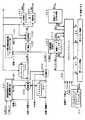
[この発明の実施形態の構成]
次に、この発明による画像データ処理方法および装置の実施形態を、図を参照しながら説明する。図1は、この発明による画像データ処理装置の実施形態が適用された撮像装置のブロック図を示すものである。[Configuration of Embodiment of the Invention]
Next, embodiments of an image data processing method and apparatus according to the present invention will be described with reference to the drawings. FIG. 1 is a block diagram of an imaging apparatus to which an embodiment of an image data processing apparatus according to the present invention is applied.
図1に示すように、撮像レンズ1Lを備えるカメラ光学系1を通じた被写体からの入射光は、撮像素子2に照射されて撮像される。この例では、撮像素子2は、前述したようにX−Yアドレス型の固体撮像素子の一例であるCMOSイメージャで構成されている。 As shown in FIG. 1, incident light from a subject through a camera
この例では、撮像素子2からは、タイミング信号発生部4からのタイミング信号により1ライン単位が同時に取り出される(サンプリングされる)ことによりアナログ撮像信号とされて出力される。そして、出力されたアナログ撮像信号は、データ変換部3に供給される。 In this example, one line unit is simultaneously taken out (sampled) by the timing signal from the
データ変換部3は、これに入力されたアナログ撮像信号に必要な補正処理を加えた後、タイミング信号発生部4からのクロック信号に同期してデジタル撮像信号に変換する。そして、データ変換部3は、デジタル撮像信号を輝度信号成分と色差信号成分とからなる撮像画像データDinに変換し、その撮像画像データDinを信号処理部5に供給する。 The
信号処理部5は、データ変換部3からの撮像画像データDinについて、これに接続されている画像メモリ6への書き込み/読み出しを制御しながら、手ぶれ補正およびレンズ歪み補正の補正処理や、撮像画像の電子ズーム処理(電子的拡大・縮小処理)を行なうとともに、指定された解像度の出力画像データDoutを生成して出力する。 The
画像メモリ6は、1個のメモリで構成されるが、4つのバンクBANK0,BANK1,BANK2,BANK3に分割されている。また、この実施形態では、画像メモリ6は、信号処理部5に含まれるメモリ制御部によるアドレス管理および書き込み/読み出し制御により、第1メモリ領域61と第2メモリ領域62との2つのメモリ領域に分割されて使用される。つまり、画像メモリの4つのバンクBANK0,BANK1,BANK2,BANK3は、それぞれ第1メモリ領域61と、第2メモリ領域62とに分割されて使用される。 The
そして、この実施形態では、図7に示すように、第1メモリ領域61と第2メモリ領域62との分割点のアドレス(セパレートアドレス)SepAdrは、4つのバンクBANK0,BANK1,BANK2,BANK3について同一とされ、かつ、このセパレートアドレスSepAdrは、対象となる画像処理に応じて、後述するように、変更されるようにされている。 In this embodiment, as shown in FIG. 7, the addresses (separate addresses) SepAdr of the dividing points of the
このセパレートアドレスSepAdrは、後述するように、制御部10から信号処理部5に与えられて、設定される。制御部10には、ユーザインターフェース9を通じて、ユーザによる出力解像度の選択入力、電子ズーム率の入力、手ぶれ補正の有無の入力、レンズ歪み補正の有無の入力などが供給されており、制御部10は、当該入力情報に基づいて、セパレートアドレスSepAdrを決定する。その決定方法については後述する。 As will be described later, the separate address SepAdr is given from the
後述もするように、この実施形態では、第1メモリ領域61には、水平方向の画像処理結果の撮像画像データが書き込まれる。そして、この第1メモリ領域61に、垂直方向の画像処理が開始できるだけの容量の撮像画像データが書き込まれると、当該書き込まれた撮像画像データが、その先頭から読み出される。そして、第1メモリ領域61から読み出された撮像画像データは、垂直方向の画像処理がなされた後、その垂直方向の画像処理結果の撮像画像データが第2メモリ領域62に書き込まれる。 As will be described later, in this embodiment, captured image data as a result of image processing in the horizontal direction is written in the
そして、この実施形態においては、画像データの画像メモリ6に対する書き込みおよび読み出しは、複数画素単位でなされる。ここで、書き込み及び読み出しの単位とされる複数画素の画素数は、1ラインの有効画素数の1/N(Nは2以上の正の整数)であることが好ましく、この例では、8画素単位でなされる。 In this embodiment, writing and reading of image data to and from the
そして、後述するように、画像メモリ6の4個のバンクBANK0,BANK1,BANK2,BANK3に対する画像データの書き込みは、所定のデータ長、例えば1ライン分ごとに、バンクを順次に切り換えて行ない、また、画像データの画像メモリ領域からの読み出しは、前記所定のデータ長分について、複数の前記バンクから同時に行なう。 As will be described later, writing of image data to the four banks BANK0, BANK1, BANK2, and BANK3 of the
すなわち、例えば、1つのバンクに、例えば1ライン分を書き込むと、次のバンクに次の1ライン分を書き込むというようにして、4個全てのバンクにそれぞれ1ライン分を書き込んだら、最初のバンクに戻って次の1ライン分を書き込むようにする。以降、同じ動作を続けることにより、画像の書き込みを行なう。 That is, for example, if one line is written to one bank, then the next bank is written to the next bank, and one line is written to all four banks. Return to, and write the next line. Thereafter, the image is written by continuing the same operation.
また、画像メモリ6からの画像データの読み出しは、例えば、連続する2ライン分を、2個のバンクから同時に読み出す、あるいは、連続する4ライン分を、4個のバンクから同時に読み出すようにする。 In addition, for reading image data from the
画像メモリ6の4個のバンクBANK0,BANK1,BANK2,BANK3の第1メモリ領域61および第2メモリ領域62は、後述するように、FIFO(First−In First−Out)動作により書き込みながら読み出しを行なうように制御されて、遅延は、あるものの、撮像画像データのリアルタイム処理がなされる。この場合に、この実施形態では、各バンクBANK0,BANK1,BANK2,BANK3の第1メモリ領域61および第2メモリ領域は、それぞれリングメモリバッファとして用いるようにアドレス制御される。 The
そして、第1メモリ領域61の記憶容量(4バンクの第1メモリ領域の合計の容量)は、垂直方向の画像処理が開始できるだけの容量に所定のマージン分を加えたものでよいので、1画面分(1フィールドあるいは1フレーム)以下とされる。この実施形態では、第1メモリ領域61の記憶容量(4バンクの第1メモリ領域の合計の容量)は、少なくとも垂直解像度変換用のデジタルフィルタのタップ数に応じた画像ライン数分の容量を必要とする。 The storage capacity of the first memory area 61 (the total capacity of the first memory areas of the four banks) may be a capacity that can start image processing in the vertical direction plus a predetermined margin. Minutes (one field or one frame) or less. In this embodiment, the storage capacity of the first memory area 61 (the total capacity of the first memory areas of four banks) needs to be at least as large as the number of image lines corresponding to the number of taps of the digital filter for vertical resolution conversion. And
一方、第2メモリ領域62(4バンクの第2メモリ領域の合計の容量)には、この実施形態では、少なくとも解像度変換後の出力画像データDoutの1画面分を記憶する記憶容量が必要である。つまり、第2メモリ領域62の記憶容量(4バンクの第2メモリ領域の合計の容量)は、出力画像データDoutの1画面分(1フィールド分または1フレーム分)以上である必要がある。 On the other hand, in this embodiment, the second memory area 62 (total capacity of the second memory areas of four banks) needs to have a storage capacity for storing at least one screen of the output image data Dout after resolution conversion. . That is, the storage capacity of the second memory area 62 (the total capacity of the second memory areas of the four banks) needs to be equal to or larger than one screen (one field or one frame) of the output image data Dout.
しかし、第1メモリ領域61(4バンクの第1メモリ領域の合計の容量)および第2メモリ領域62の記憶容量(4バンクの第2メモリ領域の合計の容量)は、水平方向の処理結果のデータ量および出力画像データDoutのデータ量に依存するので、撮像素子2の画素数が変化しても、変化させる必要はない。もっとも、画像メモリ6全体の記憶容量は、選択できる解像度のうちで、最も高解像度の場合を想定して、決定される。当該画像メモリ6を用いた画像処理については、後でさらに詳述する。 However, the storage capacity of the first memory area 61 (the total capacity of the first memory areas of the four banks) and the storage capacity of the second memory area 62 (the total capacity of the second memory areas of the four banks) are the results of the horizontal processing results. Since it depends on the data amount and the data amount of the output image data Dout, it is not necessary to change even if the number of pixels of the
さらに、後述するように、各バンクの第1メモリ領域61および第2メモリ領域62では、画像データの書き込みが、その前に書き込まれた画像データの読み出しを追い越さないように、信号処理部5のメモリ制御部により、アドレス制御されるものである。 Further, as will be described later, in the
なお、この画像メモリ6に対する画像データの書き込みおよび読み出しアクセス方法の詳細については、後で詳述する。 The details of the image data writing and reading access methods to the
信号処理部5には、タイミング信号発生部4から、出力画像データの水平周期に同期する信号、すなわち、水平同期信号H−SYNCと、出力画像データの垂直周期に同期する信号、すなわち、垂直同期信号V−SYNCと、1画素周期のクロック信号CLKと、それらに同期するクロックが、処理タイミング信号として供給される(図1では、これらの信号の図示は省略)。 The
また、撮影時に撮像装置を保持している撮影者による手ぶれ速度を検出する手ぶれ速度検出部7が設けられる。この手ぶれ速度検出部7は、撮像素子2の、撮像画像の水平方向および/または垂直方向の、所定速度以上の比較的高速の位置的変化を手ぶれとして、その速度ベクトルを検出する。ここで、比較的高速の位置的変化としたのは、撮影者による撮像装置のパンニング操作(左右方向への移動)や、チルティング操作(上下方向の移動)を、手ぶれとして検出しないためである。 In addition, a camera shake
この手ぶれ速度検出部7は、例えば撮像装置の筐体に取付けられた角速度センサにより構成される。この手ぶれ速度検出部7の検出出力は、手ぶれ速度ベクトルである。この手ぶれ速度検出部7は、角速度センサの代わりに加速度センサを用いて構成しても良い。加速度センサを用いる場合には、加速度センサ値(方向成分も含む)を積分することで、手ぶれ速度(手ぶれ速度ベクトル)を検出し、手ぶれ速度検出部7の検出出力とするようにする。 The camera shake
この手ぶれ速度検出部7の検出出力は、手ぶれ速度検出処理部8に供給される。この手ぶれ速度検出処理部8には、タイミング信号発生部4からサンプリング信号Spが供給され、このサンプリングSpにより前記手ぶれ速度検出部7の検出出力(手ぶれ速度ベクトル)がサンプリングされて、前述した各分割画像区間Pdiv_0〜Pdiv_7についての8個の手ぶれ速度ベクトルVec_0〜Vec_7が求められる。 The detection output of the camera shake
そして、手ぶれ速度検出処理部8では、8個の手ぶれ速度ベクトルVec_0〜Vec_7を、その水平方向成分と、垂直方向成分とに分離し、それら水平方向成分および垂直方向成分の逆符号成分を水平補正速度成分および垂直補正速度成分として生成する。そして、生成した水平補正速度成分および垂直補正速度成分を信号処理部5に供給する。 Then, the camera shake speed
また、この例の撮像装置は、全体を制御するためのマイクロコンピュータを搭載する制御部10を備える。この制御部10には、ユーザインターフェース9が接続されている。そして、このユーザインターフェース9を通じて、ユーザからの画像拡大・縮小指示入力や、解像度指示入力、また、ズーム倍率の値の指示入力などが制御部10に与えられる。制御部10は、それらの指示入力に応じた制御信号を形成し、タイミング信号発生部4や信号処理部5に供給する。 In addition, the imaging apparatus of this example includes a
また、この実施形態では、制御部10は、ユーザインターフェース9を通じた前述の画像処理に関する入力に応じて、画像メモリ6の第1メモリ領域61と第2メモリ領域との分割点アドレスとしてのセパレートアドレスSepAdrを設定し、信号処理部5に供給するようにする。信号処理部5のメモリ制御部は、このセパレートアドレスSepAdrにより、第1メモリ領域61と第2メモリ領域62とを認識して、これらのメモリ領域に対する画像データの書き込みおよび読み出しを実行する。 In this embodiment, the
また、レンズ歪み補正用データ導出・エンコード部11が設けられる。この補正用データ導出・エンコード部11は、ユーザインターフェース9を通じて入力されたレンズ1Lの歪曲収差に関するデータおよび制御部10からの光学ズームの操作情報に応じた撮像レンズの光軸位置に関する情報などから、撮像素子2の全画素の撮像素子2上の各位置に応じたレンズ歪み補正ベクトルを予め計算する。そして、補正用データ導出・エンコード部11は、求めた補正ベクトルを圧縮するなどしてエンコードし、レンズ歪み補正用データデコード部12に供給する。 A lens distortion correction data derivation /
この補正用データ導出・エンコード部11は、非常に負荷の大きな演算が必要となるので、専用のマイクロコンピュータやDSP(Digital Signal Processor)が用いられて構成される。 The correction data derivation /
レンズ歪み補正用データデコード部12は、レンズ歪み水平補正量データデコード部121と、レンズ歪み垂直補正量データデコード部122とを備える。そして、補正用データ導出・エンコード部11からのレンズ歪み補正ベクトルから、レンズ歪み水平補正量データデコード部121は、レンズ歪み水平補正量データを生成し、レンズ歪み垂直補正量データデコード部122は、レンズ歪み垂直補正量データを生成する。 The lens distortion correction
そして、レンズ歪み水平補正量データデコード部121、レンズ歪み垂直補正量データデコード部122のそれぞれは、信号処理部5からの歪み補正対象部位としての画素位置の情報を引数として受けて、当該画素位置における水平レンズ歪み補正量データ、垂直レンズ歪み補正量データをそれぞれ信号処理部5に返す。 Then, each of the lens distortion horizontal correction amount
信号処理部5では、画像メモリ6への画像データの書き込み/読み出しを制御しながら、後で詳述するようにして、手ぶれ速度検出処理部8からの水平補正速度成分と垂直補正速度成分とから、各水平ラインの水平補正変位量SX_ADDおよび垂直補正変位量SY_ADDを算出する。 The
そして、信号処理部5では、これら算出した水平補正変位量SX_ADDおよび垂直補正変位量SY_ADDと、前記レンズ歪み補正データデコード部12からのレンズ歪み水平補正量データおよびレンズ歪み垂直補正量データとを用いて、データ変換部3からの撮像画像データDinについての手ぶれによる画像歪み補正処理およびレンズ歪みを補正処理し、出力画像データDoutを得る。 The
なお、前述したように、信号処理部5では、上述の歪み補正処理の他、電子ズーム(画像拡大・縮小)処理を行なうと共に、標準精細度、高精細度などに応じた解像度変換処理なども行なう。 As described above, the
信号処理部5からの出力画像データDoutは、記録処理部13により例えばデータ圧縮されると共に、記録メディア14への記録に適した変調が施された後、記録メディア10に記録される。記録メディア14としては、磁気テープや磁気ディスクなどの磁気記録媒体、DVD(Digital Versatile Disc)などの光ディスク媒体、ハードディスク、カード型メモリなどを用いることができる。なお、出力撮像画像データをインターネットやワイヤレス通信手段を介して記録メディア14に記憶するようにすることもできる。 The output image data Dout from the
信号処理部5からの出力画像データDoutは、また、表示系処理部15を通じて表示モニターとしての、例えばLCD(Liquid Crystal Display)などのディスプレイに供給され、画像表示される。記録メディア14に記録された撮像画像データも、再生処理部16により再生され、表示系処理部15を通じて表示モニターに供給され、再生画像表示される。 The output image data Dout from the
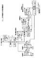
次に、図1の信号処理部5、画像メモリ6、手ぶれ速度処理部8の部分の、より詳細な構成ブロック図を図8に示す。 Next, FIG. 8 shows a more detailed configuration block diagram of the
すなわち、手ぶれ補正およびレンズ歪み補正処理や電子ズーム処理、解像度変換処理、出力データ生成処理のために、信号処理部5は、水平処理ブロック51と、垂直処理ブロック52と、レジスタブロック53と、メモリ制御部の機能を備えるメモリインタフェース54とを含んでいる。そして、水平処理ブロック51は、水平処理用手ぶれ補正量積分部511と水平画像処理部512とを備え、また、垂直処理ブロック52は、垂直処理用手ぶれ補正量積分部521と垂直画像処理部522とを備える。 That is, for the camera shake correction and lens distortion correction processing, electronic zoom processing, resolution conversion processing, and output data generation processing, the
また、水平画像処理部512に対して、レンズ歪み水平補正量データデコード部121が接続され、垂直画像処理部522に対して、レンズ歪み垂直補正量データデコード部122が接続される。 A lens distortion horizontal correction amount
水平処理ブロック51は、データ変換部3からの撮像画像データDinに対して水平方向の処理を施す。この水平方向の処理には、水平方向の手ぶれ補正およびレンズ歪み補正処理、水平方向の画像拡大・縮小処理、水平方向の解像度変換を含む。垂直処理ブロック52は、撮像画像データDinに対して垂直方向の処理を施す。この垂直方向の処理には、垂直方向の手ぶれ補正およびレンズ歪み補正処理、垂直方向の画像拡大・縮小処理、垂直方向の解像度変換を含む。 The
また、レジスタブロック53は、手ぶれ速度検出処理部8で検出された手ぶれ速度の情報を、水平処理ブロック51および垂直処理ブロック52に受け渡す処理を行なう。レジスタブロック53は、また、画像メモリ6のセパレートアドレスSepAdrを、メモリインタフェース54に受け渡す処理も行なう。 In addition, the register block 53 performs processing for transferring the information on the camera shake speed detected by the camera shake speed
手ぶれ速度検出部8は、サンプリング部81と、水平補正速度成分検出部82と、垂直補正速度成分検出部83とからなる。 The camera shake
サンプリング部81では、手ぶれ検出部7からの手ぶれ速度検出出力(図9(A)参照)を、タイミング信号発生部4からのサンプリング信号Spによりサンプリングすることにより、各分割画像区間Pdiv_0〜Pdiv_7についての手ぶれ速度ベクトルVec_0〜Vec_7(図9(B)参照)を取得する。この例では、サンプリング部81では、前述したように、手ぶれ速度ベクトルVec_0〜Vec_7は、各分割画像区間Pdiv_0〜Pdiv_7の先頭ラインに対するものが、垂直周期の1/8の周期でサンプリングされる。 In the
ここで、取得すべき各手ぶれ速度ベクトルの値は、撮像素子2からの撮像画像データの対応する水平ラインのサンプリング時刻の値ではない。なぜなら、前述したように、撮像素子2上の各画素には露光時間があり、撮像素子2から取り出された撮像信号(色フィルタを通過した後の輝度値)は、各ラインのサンプリング時刻から露光時間分遡った時刻までの平均値であるからである。 Here, the value of each camera shake velocity vector to be acquired is not the value of the sampling time of the corresponding horizontal line of the captured image data from the
このため、この実施形態では、手ぶれ速度ベクトルの値の検出点は、図10に示すように、各水平ラインの画像データのサンプリング時刻tsと、当該サンプリング時刻tsから露光時間分遡った時刻tbとの間の中央時刻となるように、サンプリング信号Spによるサンプリングタイミングが設定されている。 For this reason, in this embodiment, the detection point of the value of the camera shake velocity vector is, as shown in FIG. 10, the sampling time ts of the image data of each horizontal line, and the time tb retroactive by the exposure time from the sampling time ts. The sampling timing by the sampling signal Sp is set so as to be the central time between.
露光時間が短くなければ、水平ラインの画像データの先頭のタイミングでは、手ぶれ速度ベクトルの値を確定することができるが、露光時間が短くなった場合には、水平ラインの画像データの先頭のタイミングでは、手ぶれ速度ベクトルの値を確定することができない場合が生じる。そのような場合には、サンプリング部81では、過去の手ぶれ速度ベクトルを参照して、手ぶれ速度ベクトルの値を予測するようにする。 If the exposure time is not short, the value of the camera shake velocity vector can be determined at the start timing of the horizontal line image data, but if the exposure time is shortened, the start timing of the horizontal line image data. Then, there is a case where the value of the camera shake velocity vector cannot be determined. In such a case, the
このサンプリング部81でサンプリングされて得られる、1フレーム(1垂直周期)について、8個の手ぶれ速度ベクトルVec_0〜Vec_7は、水平補正速度成分検出部82および垂直補正速度成分検出部83に供給される。 For one frame (one vertical cycle) obtained by sampling by the
水平補正速度成分検出部82では、各分割画像区間Pdiv_0〜Pdiv_7における手ぶれ速度ベクトルVec_0〜Vec_7の水平方向成分を抽出し、その逆符号成分として、水平補正速度成分X_STB_0〜X_STB_7(図9(C)参照)を求める。 The horizontal correction speed component detection unit 82 extracts the horizontal direction components of the camera shake speed vectors Vec_0 to Vec_7 in the divided image sections Pdiv_0 to Pdiv_7, and uses the horizontal correction speed components X_STB_0 to X_STB_7 (FIG. 9C) as the inverse sign components. Request).
また、垂直補正速度成分検出部9では、各分割画像区間Pdiv_0〜Pdiv_7における手ぶれ速度ベクトルVec_0〜Vec_7の垂直方向成分を抽出し、その逆符号成分として、垂直補正速度成分Y_STB_0〜Y_STB_7(図9(D)参照)を求める。 Further, the vertical correction speed
この場合に、この実施形態では、水平補正速度成分X_STB_0〜X_STB_7および垂直補正速度成分Y_STB_0〜Y_STB_7のそれぞれの値は、1水平ライン区間の時間長当たりの手ぶれ補正量として求められる。 In this case, in this embodiment, the values of the horizontal correction speed components X_STB_0 to X_STB_7 and the vertical correction speed components Y_STB_0 to Y_STB_7 are obtained as camera shake correction amounts per time length of one horizontal line section.
すなわち、水平補正速度成分X_STB(X_STB_0〜X_STB_7)は、
X_STB=(水平手ぶれ補正量/1水平ライン区間の時間長)
とされる。That is, the horizontal correction speed component X_STB (X_STB_0 to X_STB_7)
X_STB = (horizontal image stabilization amount / time length of one horizontal line section)
It is said.
また、垂直補正速度成分Y_STB(Y_STB_0〜Y_STB_7)は、
Y_STB=(水平手ぶれ補正量/1水平ライン区間の時間長)
とされる。The vertical correction speed component Y_STB (Y_STB_0 to Y_STB_7)
Y_STB = (horizontal image stabilization amount / time length of one horizontal line section)
It is said.
そして、水平補正速度成分X_STB_0〜X_STB_7は、水平方向の画素ピッチ(画素の間隔)dxの倍数値(小数点以下の値を取り得る。以下同じ)、換言すれば、水平方向の画素数(小数点以下を取り得る)で表わされる。また、垂直補正速度成分Y_STB_0〜Y_STB_7は、垂直方向の画素ピッチ(画素の間隔)dyの倍数値(小数点以下を取り得る)、換言すれば、垂直方向の画素数(小数点以下を取り得る。以下同じ)で表わされる。 The horizontal correction speed components X_STB_0 to X_STB_7 are multiples of the horizontal pixel pitch (pixel interval) dx (can take values after the decimal point; the same applies hereinafter), in other words, the number of pixels in the horizontal direction (below the decimal point). Can be taken). Further, the vertical correction speed components Y_STB_0 to Y_STB_7 can be a multiple of the vertical pixel pitch (pixel interval) dy (can take a decimal point), in other words, the number of vertical pixels (below the decimal point. The same).
これは、サンプリング部81からの手ぶれ速度出力の水平方向成分と、垂直方向成分のそれぞれに対して、「速度成分の値→画素数(小数点以下の値を取り得る。以下同じ)の値」の対応テーブルを用意し、速度成分の値を入力値として、画素数の値を得るようにすることで実現される。そして、得られた画素数の値について、手ぶれの速度成分の方向とは逆方向に対応する符号を付加して、それぞれ、水平補正速度成分X_STB_0〜X_STB_7および垂直補正速度成分Y_STB_0〜Y_STB_7とするものである。 This means that for each of the horizontal direction component and the vertical direction component of the camera shake speed output from the
この実施形態では、このように水平補正速度成分X_STB_0〜X_STB_7および垂直補正速度成分Y_STB_0〜Y_STB_7の値を定めることにより、後述するライン単位の時間積分計算による水平手ぶれ補正量SX_ADDおよび垂直手ぶれ補正量SY_ADDを、水平補正速度成分および垂直補正速度成分の単純加算により行なえるようにしている。 In this embodiment, by determining the values of the horizontal correction speed components X_STB_0 to X_STB_7 and the vertical correction speed components Y_STB_0 to Y_STB_7 in this way, the horizontal camera shake correction amount SX_ADD and the vertical camera shake correction amount SY_ADD are calculated by the line-by-line time integration calculation described later. Can be performed by simple addition of the horizontal correction speed component and the vertical correction speed component.
そして、これら水平補正速度成分検出部82および垂直補正速度成分検出部83で算出された水平補正速度成分X_STB_0〜X_STB_7および垂直補正速度成分Y_STB_0〜Y_STB_7は、タイミング信号発生部4からのタイミング信号Stに応じたタイミングで、信号処理部5のレジスタブロック53のIF(インターフェース)レジスタ(図示は省略)に、順次取り込まれる。 The horizontal correction speed components X_STB_0 to X_STB_7 and the vertical correction speed components Y_STB_0 to Y_STB_7 calculated by the horizontal correction speed component detection unit 82 and the vertical correction speed
そして、取り込まれた水平補正速度成分X_STB_0〜X_STB_7および垂直補正速度成分Y_STB_0〜Y_STB_7は、水平処理ブロック51および垂直処理ブロック52での処理タイミングに対応して、レジスタブロック53内の水平処理ブロック用レジスタおよび垂直処理ブロック用レジスタ(何れも図示は省略)に、前記IFレジスタから、前記取り込まれたタイミングとは別のタイミングで、転送される。 Then, the horizontal correction speed components X_STB_0 to X_STB_7 and the vertical correction speed components Y_STB_0 to Y_STB_7 that are taken in are registered in the register for horizontal processing block in the register block 53 in accordance with the processing timing in the
水平処理ブロック51および垂直処理ブロック52の水平処理用手ぶれ補正量積分部511および垂直処理用手ぶれ補正量積分部521は、レジスタブロック53の水平処理ブロック用レジスタおよび垂直処理ブロック用レジスタに取り込まれている各分割画像区間Pdiv_0〜Pdiv_7の水平補正速度成分X_STB_0〜X_STB_7および垂直補正速度成分Y_STB_0〜Y_STB_7を積分することにより、各分割画像区間Pdiv_0〜Pdiv_7における各水平ラインに対する水平手ぶれ補正量SX_ADDおよび垂直手ぶれ補正量SY_ADDを算出する。 The horizontal processing camera shake correction
水平処理ブロック51の水平画像処理部512では、水平処理用手ぶれ補正量積分部511で算出された水平手ぶれ補正量SX_ADDを用いて、水平方向の手ぶれ成分を補正するように、各水平ラインの画素データのx座標を、水平方向にシフトする。また、水平方向のレンズ歪みを補正するために当該画素のy座標が必要になることを考慮して、垂直処理用手ぶれ補正量積分部521で算出された垂直手ぶれ補正量SY_ADDを用いて、当該補正対象部位の画素データのy座標を、垂直方向の手ぶれ成分を補正するようにシフトしたものとして求める。 The horizontal
そして、水平画像処理部512は、当該手ぶれに応じて水平方向および垂直方向にシフトした各画素データのx座標と、y座標とを、引数としてレンズ歪み水平補正量データデコード部121に供給し、このレンズ歪み水平補正量データデコード部121から、当該x座標およびy座標位置の画素位置に対するレンズ歪み水平補正量データ(水平方向の座標シフト量)を得る。 Then, the horizontal
そして、水平画像処理部512は、水平手ぶれ補正量SX_ADDを用いて補正したx座標データに、取得したレンズ歪み水平補正量データを加算して、さらにシフトする。そして、当該シフトされたx座標データを用いて、水平方向の手ぶれ成分およびレンズ歪みの水平方向成分を補正する。 Then, the horizontal
また、垂直処理ブロック52の垂直画像処理部522では、垂直処理用手ぶれ補正量積分部521で算出された垂直手ぶれ補正量SY_ADDを用いて、垂直方向の手ぶれ成分を補正するように、各水平ラインの画素データのy座標を、垂直方向にシフトする。また、垂直方向のレンズ歪みを補正するために当該画素のx座標が必要になることを考慮して、水平処理用手ぶれ補正量積分部511で算出された水平手ぶれ補正量SX_ADDを用いて、当該補正対象部位の画素データのx座標を、水平方向の手ぶれ成分を補正するようにシフトしたものとして求める。 In addition, the vertical
そして、垂直画像処理部522は、当該手ぶれに応じて水平方向および垂直方向にシフトした各画素データのx座標とy座標とを、引数としてレンズ歪み垂直補正量データデコード部122に供給し、このレンズ歪み垂直補正量データデコード部122から、当該x座標およびy座標位置の画素位置に対するレンズ歪み垂直補正量データ(垂直方向の座標シフト量)を得る。 Then, the vertical
そして、垂直画像処理部522は、垂直手ぶれ補正量SY_ADDを用いて補正したy座標データに、取得したレンズ歪み垂直補正量データを加算して、さらにシフトする。そして、当該シフトされたy座標データを用いて、垂直方向の手ぶれ成分およびレンズ歪みの垂直方向成分を補正する。 Then, the vertical
以上の補正処理においては、水平処理ブロック51の水平画像処理部512および垂直処理ブロック52の垂直画像処理部522では、それぞれ画像メモリ6に対して画像データの読み書きをしながら補正処理を実行するようにする。 In the above correction processing, the horizontal
この実施形態では、画像メモリ6は、前述したように、メモリインタフェース54によるアドレス管理に基づいて、第1メモリ領域61と第2のメモリ領域62とに論理的に分割されており、第1メモリ領域61には、水平処理ブロック51の水平画像処理部512で処理された結果の撮像画像データが書き込まれる。 In this embodiment, the
この例では、第1メモリ領域61は、後述する垂直方向の補間処理用のFIR(Finite Impulse Response)フィルタのタップ数以上のライン数分の容量を有する。この垂直方向の補間処理用のFIRフィルタは、垂直方向の手ぶれ補正用フィルタ、垂直方向のレンズ歪み補正用フィルタおよび垂直解像度変換フィルタを構成しているものである。 In this example, the
そして、この第1メモリ領域61に必要な記憶容量は、上記の垂直処理用のFIRフィルタのタップ数のみではなく、電子ズーム率、レンズ歪み補正率、手ぶれ補正率にしたがって変化する。 The storage capacity required for the
第1メモリ領域61に垂直画像処理を開始することができる画像データが書き込まれると、この第1メモリ領域61から画像データが読み出されて、垂直ブロック52の垂直画像処理部522で垂直方向の画像処理がなされ、その処理結果が第2メモリ領域62に書き込まれる。そして、この第2メモリ領域62から出力画像データDoutが読み出される。 When image data capable of starting the vertical image processing is written in the
したがって、この第2メモリ領域の記憶容量としては、出力画像データDoutの1画面分(1フィールドまたは1フレーム)の容量が最低必要とされる。 Therefore, as the storage capacity of the second memory area, the capacity of one screen (one field or one frame) of the output image data Dout is required at the minimum.
水平処理ブロック51の水平画像処理部512には、後述するように、1ライン分の容量の水平処理用FIFOラインメモリが設けられ、この水平処理用FIFOラインメモリへの画像データの書き込み、読み出しを制御するFIFOメモリコントローラ(図8では図示を省略)が設けられていると共に、算出した水平手ぶれ補正量SX_ADDが小数点以下(補正後の画素位置が、水平方向の画素位置よりオフセットされた位置となる)の場合を想定し、補間処理を行なう水平方向補間処理部(図8では図示を省略)が設けられている。この水平方向補間処理部は、後述するように、この実施形態では、水平方向のデジタルFIRフィルタ(以下、水平FIRフィルタという)が用いられる。 As will be described later, the horizontal
なお、1ライン分の容量の水平処理用FIFOラインメモリも、画像メモリ6の一部のメモリ領域として設定しておき、FIFOメモリコントローラを、メモリインタフェース54により構成するようにしても良い。 A horizontal processing FIFO line memory having a capacity of one line may be set as a partial memory area of the
そして、メモリインタフェース54は、第1メモリ領域61への水平画像処理後の画像データの書き込みを制御すると共に、第1メモリ領域61からの画像データの読み出しを制御して、垂直処理ブロック52の画像処理部522に供給する。また、メモリインタフェース54は、画像処理部522で垂直方向処理がなされた画像データの、第2のメモリ領域62への書き込み、読み出しを制御する。 Then, the
第2メモリ領域62から読み出された画像データは、画像データ出力部523に供給され、この画像データ出力部523から出力画像データDoutが導出される。 The image data read from the
また、垂直処理ブロック52の垂直画像処理部522には、算出した垂直手ぶれ補正量SY_ADDが小数点以下(補正後の画素位置が、垂直方向の画素位置よりオフセットされた位置となる)の場合を想定し、補間処理を行なう垂直方向補間処理部(図8では図示を省略)が設けられている。この垂直方向補間処理部は、後述するように、この実施形態では、垂直方向のデジタルFIRフィルタ(以下、垂直FIRフィルタという)が用いられるが、レンズ歪み補正のために必要なライン数および垂直解像度変換を考慮したタップ数とされる。 Further, the vertical
ここで、算出した水平手ぶれ補正量SX_ADDとレンズ歪み水平補正量との加算量および垂直手ぶれ補正量SY_ADDとレンズ歪み垂直補正量との加算量が小数点以下の値を持つ場合の補間処理について説明する。 Here, an interpolation process when the calculated amount of addition of the horizontal camera shake correction amount SX_ADD and the lens distortion horizontal correction amount and the addition amount of the vertical camera shake correction amount SY_ADD and the lens distortion vertical correction amount have values after the decimal point will be described. .
まず、手ぶれ補正について説明する。例えば、手ぶれの水平方向の速度成分により、水平方向に図11に示すような画像歪みが生じた場合を想定する。すなわち、図11の例は、手ぶれが無ければ破線で示す直線上にあるべき画素G11,G21,G31・・・、G12,G22,G32・・・、G13,G23,G33・・・、が、手ぶれの水平方向の速度成分のために実線で示すような斜め位置となっている場合である。 First, camera shake correction will be described. For example, a case is assumed where image distortion as shown in FIG. 11 occurs in the horizontal direction due to the velocity component in the horizontal direction of camera shake. That is, in the example of FIG. 11, pixels G11, G21, G31..., G12, G22, G32... G13, G23, G33. This is a case where the camera is in an oblique position as indicated by a solid line due to the horizontal velocity component of camera shake.
この手ぶれを補正するためには、ずれている画素位置を本来の位置にあるようにずらせばよく、そのずれ量が、図11に示すように、前述した水平手ぶれ補正量SX_ADDに相当する。この水平手ぶれ補正量SX_ADDが、画素ピッチdxの整数倍であれば、画素データを当該水平手ぶれ補正量SX_ADDに応じた画素ピッチ分だけずらして読み出すようにすることで補正することができる。 In order to correct this camera shake, it is only necessary to shift the shifted pixel position so that it is in its original position, and the shift amount corresponds to the above-mentioned horizontal camera shake correction amount SX_ADD as shown in FIG. If the horizontal camera shake correction amount SX_ADD is an integral multiple of the pixel pitch dx, the pixel data can be corrected by being read out while being shifted by the pixel pitch corresponding to the horizontal camera shake correction amount SX_ADD.
しかしながら、水平手ぶれ補正量SX_ADDが、画素ピッチdxの整数倍ではなく、小数点以下のずれ量を含む場合には、そのずれ量に対応する位置は、画素データが存在する位置ではないので、その位置の近傍の複数個の画素データを用いた補間処理により、対応する画素位置の画素データを生成する必要がある。 However, when the horizontal camera shake correction amount SX_ADD is not an integral multiple of the pixel pitch dx and includes a shift amount below the decimal point, the position corresponding to the shift amount is not a position where pixel data exists, so that position It is necessary to generate pixel data at a corresponding pixel position by interpolation processing using a plurality of pixel data in the vicinity of.
図12は、その補間方法の一例を示すもので、求める画素データが、画素G1と画素G2との間の補間画素Gsである場合に、この補間画素Gsの位置と画素G1,G2の位置との距離k1,k2に応じた割合で、画素G1のデータと画素G2のデータとを加算することにより、補間画素Gsの画素データを生成するものである。この場合、k1:k2=W:(1−W)としたとき、
補間画素Gs=G1×W+G2×(W−1)
なる補間演算により、補間画素Gsの画素データを得る。FIG. 12 shows an example of the interpolation method. When the pixel data to be obtained is an interpolation pixel Gs between the pixel G1 and the pixel G2, the position of the interpolation pixel Gs and the positions of the pixels G1 and G2 The pixel data of the interpolation pixel Gs is generated by adding the data of the pixel G1 and the data of the pixel G2 at a ratio corresponding to the distances k1 and k2. In this case, when k1: k2 = W: (1-W),
Interpolated pixel Gs = G1 × W + G2 × (W−1)
The pixel data of the interpolation pixel Gs is obtained by the interpolation calculation.
また、図12の例のような2個の画素データを用いるのではなく、図13の例のように2個以上(図13の例では4個)の近傍画素データを用いて、補間演算をして補間画素を求めることもできる。この場合、補間画素Gsの位置に対する画素G0,G1,G2,G3の位置との距離k0,k1,k2,k3に応じた割合となる乗算係数W0,W1,W2,W3を定めて、画素G0,G1,G2,G3のデータを加算することにより、補間画素Gsの画素データを得る。 Also, instead of using two pieces of pixel data as in the example of FIG. 12, interpolation calculation is performed using two or more (four in the example of FIG. 13) neighboring pixel data as in the example of FIG. Thus, the interpolation pixel can be obtained. In this case, multiplication coefficients W0, W1, W2, and W3 that are proportions according to distances k0, k1, k2, and k3 from the positions of the pixels G0, G1, G2, and G3 with respect to the position of the interpolation pixel Gs are determined, and the pixel G0 is determined. , G1, G2, and G3 are added to obtain pixel data of the interpolation pixel Gs.
すなわち、
補間画素Gs=G0×W0+G1×W1+G2×W2+G3×W3
なる補間演算により、補間画素Gsの画素データを得るようにする。That is,
Interpolated pixel Gs = G0 × W0 + G1 × W1 + G2 × W2 + G3 × W3
The pixel data of the interpolation pixel Gs is obtained by the interpolation calculation.
この図13の例の場合、乗算係数W0,W1,W2,W3の値の組は、画素G1または画素G2と補間画素Gsとの距離dsに対応するものとして関連付けられたテーブルを用意しておき、距離dsを検索子として、上記乗算係数W0,W1,W2,W3の組をテーブルから読み出すようにすることで得ることができる。なお、距離dsは、水平手ぶれ補正量SX_ADDの小数部に相当するものである。 In the case of the example in FIG. 13, a table associated with the set of values of the multiplication coefficients W0, W1, W2, and W3 corresponding to the distance ds between the pixel G1 or the pixel G2 and the interpolation pixel Gs is prepared. By using the distance ds as a search element, the set of the multiplication coefficients W0, W1, W2, and W3 can be read from the table. The distance ds corresponds to the decimal part of the horizontal camera shake correction amount SX_ADD.
この補間処理は、この実施形態では、水平FIRフィルタを用いて行なうようにする。すなわち、水平手ぶれ補正量SX_ADDの小数部に対応する前記乗算係数の組をテーブルから読み出し、その乗算係数を水平FIRフィルタに対して供給することで上記補間処理を行なうことができる。 In this embodiment, this interpolation processing is performed using a horizontal FIR filter. That is, the interpolation processing can be performed by reading the multiplication coefficient pair corresponding to the decimal part of the horizontal camera shake correction amount SX_ADD from the table and supplying the multiplication coefficient to the horizontal FIR filter.
以上は、水平方向の手ぶれ補正の場合の補間処理であるが、垂直方向の手ぶれ補正の場合の補間処理についても、補間方向が垂直方向になるだけで、全く同様である。 The above is the interpolation processing in the case of the horizontal direction camera shake correction, but the interpolation processing in the case of the vertical direction camera shake correction is exactly the same except that the interpolation direction becomes the vertical direction.
この手ぶれ補正の場合の補間処理動作は、この実施形態では、レンズ歪みが全く無いとした場合にのみ行なわれることになる。この実施形態では、手ぶれ補正のための補正量とレンズ歪み補正のための補正量との加算量により補正された座標位置の画素データを得るように補間処理を行なうものである。この補間処理も基本的な考え方は、上述の図12、図13の場合と全く同様である。 In this embodiment, the interpolation processing operation in the case of camera shake correction is performed only when there is no lens distortion. In this embodiment, interpolation processing is performed so as to obtain pixel data at coordinate positions corrected by an addition amount of a correction amount for camera shake correction and a correction amount for lens distortion correction. The basic concept of this interpolation process is exactly the same as in the case of FIGS.
このレンズ歪みを含む場合における補間処理を、図14を参照して説明する。なお、図14においては、x方向およびy方向にそれぞれ4つ並んだ4×4=16個からなる画素データを用いて出力画像の画素データを決定する場合の例示である。なお、このレンズ歪み補正についての補間処理の方法は、特開2004−80545公報に詳細に記載されているものを適用したものであり、詳細な説明は、上記公報に譲り、ここでは要点のみを説明する。 Interpolation processing when this lens distortion is included will be described with reference to FIG. FIG. 14 shows an example in which pixel data of an output image is determined using 4 × 4 = 16 pieces of pixel data that are arranged in the x direction and the y direction, respectively. Note that the interpolation processing method for the lens distortion correction is the one described in detail in Japanese Patent Application Laid-Open No. 2004-80545, and the detailed description is given in the above publication, and only the main points are described here. explain.
図14(A)は、歪みを伴う画像データを構成する点B1〜B4が、水平方向の補間により、それぞれ点B10〜B40の画像データに変換された様子を示す図である。また、図14(B)は、さらに垂直方向の補間により、点B10〜B40が、それぞれb1〜b4の画素データに変換された様子を示している。 FIG. 14A is a diagram illustrating a state in which points B1 to B4 constituting image data with distortion are converted into image data of points B10 to B40, respectively, by horizontal interpolation. FIG. 14B shows a state where points B10 to B40 are converted into pixel data b1 to b4, respectively, by further vertical interpolation.
この場合、この実施形態では、図14(A)の左側の歪みを伴う画像データを構成する点B1〜B4は、水平方向の手ぶれ補正量が含まれたものと考えることができる。図14(A)の場合の水平方向の補間は、各点B1〜B4のそれぞれに対して、前述した例えば図の場合を適用することで行なうことができる。つまり、水平FIRフィルタを用いる1次元補間演算でよい。 In this case, in this embodiment, it can be considered that the points B1 to B4 constituting the image data with distortion on the left side of FIG. 14A include the amount of camera shake correction in the horizontal direction. The horizontal interpolation in the case of FIG. 14A can be performed by applying the case of the above-described figure, for example, to each of the points B1 to B4. That is, a one-dimensional interpolation calculation using a horizontal FIR filter may be used.
また、図14(B)の垂直方向の場合にも同様に、図14(B)で、例えば点B30に対しては、垂直方向に連続した当該点B30を跨ぐ、破線内の4つの格子点(点K20〜K23)における画像データに、前述した図12または図13と同様の考え方による乗算係数を用いて補間処理を実行することにより、点b3の画素データが算出される。したがって、垂直方向についても、垂直FIRフィルタによる1次元補間演算でよい。 Similarly, in the case of the vertical direction in FIG. 14B as well, in FIG. 14B, for example, for the point B30, four lattice points within the broken line straddling the point B30 continuous in the vertical direction. The pixel data of the point b3 is calculated by performing interpolation processing on the image data at (points K20 to K23) using the multiplication coefficient based on the same concept as in FIG. 12 or 13 described above. Accordingly, a one-dimensional interpolation operation using a vertical FIR filter may be performed in the vertical direction.
[水平処理ブロック51における処理動作]
[水平処理用手ぶれ補正量積分部511の積分処理]
図15に、水平処理用手ぶれ補正量積分部511における積分処理動作のフローチャートを示す。[Processing Operation in Horizontal Processing Block 51]
[Integration Processing of Horizontal Processing Shake Correction Amount Integration Unit 511]
FIG. 15 shows a flowchart of the integration processing operation in the horizontal processing image stabilization
まず、初期y座標(水平ライン位置に対応)SYに、水平同期信号H−SYNC(ここでは、水平同期信号H−SYNCは、一般的な水平走査信号のうち、有効画像領域以外をマスクしたタイミング信号を意味するものとする)毎に「step」という値を加算して行く(ステップS1)。 First, the initial y-coordinate (corresponding to the horizontal line position) SY and the horizontal synchronization signal H-SYNC (here, the horizontal synchronization signal H-SYNC is a timing at which a portion other than the effective image area in the general horizontal scanning signal is masked. A value “step” is added every time the signal is assumed (step S1).
初期y座標SYは、出力画像の最初の1水平ライン目が、CMOSイメージャ上の総画素の座標系(以後絶対座標系と呼ぶ)のどこに位置するかを表しており、一般的には「0」ではない。 The initial y-coordinate SY represents where the first horizontal line of the output image is located in the coordinate system of all pixels on the CMOS imager (hereinafter referred to as an absolute coordinate system). "is not.
これは、動画時には、通常、CMOSイメージャ上の全画素が、信号処理部5に入力されるのではなく、CMOSイメージャ内で垂直方向に平均加算されてから、後段の信号処理部5に入力されるからである。また、信号処理部5に入力されてからでも、幾つかの処理を経るため、1水平ライン目の絶対座標は「0」でないことの方が多いからである。更に、入力画像データに対して、垂直方向の部分拡大処理を行なう場合には、初期y座標SYは、画面の中ほどの水平ライン位置となるので、非常に大きい値をとることもあり得るからである。 This is because, during moving images, not all pixels on the CMOS imager are normally input to the
ステップS1で、1水平同期信号H−SYNC毎に加算する「step」という値は、ライン間隔の絶対座標系における垂直座標の増量を表わすが、上述したCMOSイメージャ内もしくは水平処理ブロックの前段における、垂直方向の複数ラインの画像データの平均加算により、1以外に2や4といった値をとる可能性がある。 In step S1, the value “step” added for each horizontal synchronization signal H-SYNC represents an increase in the vertical coordinate in the absolute coordinate system of the line interval, but in the above-described CMOS imager or in the preceding stage of the horizontal processing block. There is a possibility of taking a value such as 2 or 4 in addition to 1 by averaging the image data of a plurality of lines in the vertical direction.
さて、ステップS1で、初期y座標値をSYとして、1水平同期信号H−SYNC毎に、値stepを加算することにより、現在処理している水平ラインの絶対座標が求まり、当該絶対座標の整数成分vp_i(ステップS2)が、水平補正速度成分X_STB_*(*は0〜7のいずれかである。すなわち、水平補正速度成分X_STB_*は、X_STB_0〜X_STB_7のいずれかを意味する。以下、同じ。)を、現時点までに積分すべき積分回数に対応する。ここで、この積分回数は、1画面内における積算値である。 In step S1, the initial y-coordinate value is set as SY, and the value step is added for each horizontal synchronization signal H-SYNC, thereby obtaining the absolute coordinate of the currently processed horizontal line. The component vp_i (step S2) is the horizontal correction speed component X_STB_ * (* is any one of 0 to 7. That is, the horizontal correction speed component X_STB_ * means any one of X_STB_0 to X_STB_7. The same applies hereinafter. ) Corresponds to the number of integrations to be integrated so far. Here, the number of integrations is an integrated value in one screen.
次に、現在処理している水平ライン(以下、現処理ラインという)の絶対座標の整数成分vp_iと、現処理ラインの1水平ライン前までに積分した回数(積分回数hstb_cnt)とを比較する。これにより、現処理ラインにおいて、あと何回積分すれば良いかが分かり、その回数分だけ、処理単位サイクル(1水平周期よりも十分に短い)毎にトリガTG1が発生する(ステップS3)。 Next, the integer component vp_i of the absolute coordinates of the currently processed horizontal line (hereinafter referred to as the current processing line) is compared with the number of integrations (integration count hstb_cnt) up to one horizontal line before the current processing line. As a result, it is understood how many times the current processing line should be integrated, and the trigger TG1 is generated every processing unit cycle (sufficiently shorter than one horizontal period) (step S3).
このトリガTG1が発生する毎に、積分回数hstb_cntは1づつインクリメントする(ステップS4、ステップS5)。 Each time this trigger TG1 is generated, the integration number hstb_cnt is incremented by 1 (steps S4 and S5).
そして、このトリガTG1ごとに、水平補正速度成分X_STB_0〜X_STB_7のうちの、現処理ラインが所在する分割画像区間についての水平補正速度成分を加算することにより、積分処理を行ない、水平手ぶれ補正量SX_ADDを得る(ステップS6)。ここで、図15のステップS6における「stb_x」は、水平補正速度成分X_STB_0〜X_STB_7のいずれかの値である。すなわち、「stb_x」は、現処理ラインが所在する分割画像区間についての水平補正速度成分の値である。 Then, for each trigger TG1, integration processing is performed by adding the horizontal correction speed components for the divided image section in which the current processing line is located among the horizontal correction speed components X_STB_0 to X_STB_7, and the horizontal camera shake correction amount SX_ADD. Is obtained (step S6). Here, “stb_x” in step S6 of FIG. 15 is one of the horizontal correction speed components X_STB_0 to X_STB_7. That is, “stb_x” is the value of the horizontal correction speed component for the divided image section where the current processing line is located.
また、水平レンズ歪み水平補正量データを、水平レンズ歪み水平補正量データデコード部121から取得するためには、補正対象部位の画素のx座標だけではなくy座標も必要であり、かつ、当該y座標は、CMOS手ぶれの影響を受けているため、この水平処理用手ぶれ補正量積分部511においても、垂直手ぶれ補正量SY_ADDを積分して得るようにする。 In addition, in order to acquire the horizontal lens distortion horizontal correction amount data from the horizontal lens distortion horizontal correction amount
すなわち、ステップS3で発生するトリガTG1ごとに、垂直補正速度成分Y_STB_0〜Y_STB_7のうちの、現処理ラインが所在する分割画像区間についての垂直補正速度成分を加算することにより、積分処理を行ない、垂直手ぶれ補正量SY_ADDを得る(ステップS7)。ここで、図15のステップS7における「stb_y」は、垂直補正速度成分Y_STB_0〜Y_STB_7のいずれかの値である。すなわち、「stb_y」は、現処理ラインが所在する分割画像区間についての垂直補正速度成分の値である。 That is, for each trigger TG1 generated in step S3, integration processing is performed by adding the vertical correction speed components for the divided image section in which the current processing line is located, of the vertical correction speed components Y_STB_0 to Y_STB_7. A camera shake correction amount SY_ADD is obtained (step S7). Here, “stb_y” in step S7 of FIG. 15 is any value of the vertical correction speed components Y_STB_0 to Y_STB_7. That is, “stb_y” is the value of the vertical correction speed component for the divided image section where the current processing line is located.
ステップS1で、1水平同期信号H−SYNC毎に加算される値「step」=1であって、画像の拡大などではない通常の画像出力の場合には、トリガTG1は、1水平同期信号H−SYNC毎に発生するため、ステップS6では、1水平ライン毎に「stb_x」を加算(積分)し、ステップS7では1水平ライン毎に「stb_y」を加算(積分)するものである。 In step S1, the value “step” added for each horizontal synchronization signal H-SYNC = 1, and in the case of normal image output that is not image enlargement or the like, the trigger TG1 is set to one horizontal synchronization signal H. Since this occurs every SYNC, “stb_x” is added (integrated) for each horizontal line in step S6, and “stb_y” is added (integrated) for each horizontal line in step S7.
こうして得られる水平手ぶれ補正量SX_ADDは、前述もしたように、CMOSイメージャ上での各水平ラインの水平方向の読み出し開始位置の補正量、すなわち、水平処理ブロック51における水平方向画像歪み補正処理における各ラインの水平初期位置(水平オフセット)そのものとなる。補正対象部位としての水平ラインの各画素のx座標は、この水平手ぶれ補正量SX_ADDだけ、水平方向にシフトされたものとなる。 As described above, the horizontal camera shake correction amount SX_ADD obtained in this way is the correction amount of the horizontal readout start position of each horizontal line on the CMOS imager, that is, each horizontal image distortion correction process in the
また、垂直手ぶれ補正量SY_ADDは、CMOSイメージャ上での各水平ラインの垂直方向の座標シフト量となる。この値は、同一水平ライン内では同じであり、したがって、補正対象部位としての水平ラインの各画素のy座標は、当該垂直手ぶれ補正量SY_ADDだけ、垂直方向にシフトされたものとなる。 The vertical camera shake correction amount SY_ADD is a vertical coordinate shift amount of each horizontal line on the CMOS imager. This value is the same in the same horizontal line. Therefore, the y coordinate of each pixel of the horizontal line as the correction target part is shifted in the vertical direction by the vertical camera shake correction amount SY_ADD.
このように、水平手ぶれ補正量SX_ADDおよび垂直手ぶれ補正量SY_ADDにより、CMOS手ぶれに応じて補正された画素位置の情報は、後述するように、当該画素位置における水平方向のレンズ歪みを取得するための情報として用いられる。 As described later, the pixel position information corrected in accordance with the CMOS camera shake by the horizontal camera shake correction amount SX_ADD and the vertical camera shake correction amount SY_ADD is used to acquire the horizontal lens distortion at the pixel position as described later. Used as information.
上述したように、ステップS6およびステップS7では、現処理ラインが、1画面分(1フレーム=1垂直同期周期)を垂直方向に8分割した分割画像区間のどこに属するかによって、水平補正速度成分X_STB_0〜X_STB_7のうちのいずれか1つ、および垂直補正速度成分Y_STB_0〜Y_STB_7のうちのいずれか1つを選択しなければならない。そのための仕組みが、図15の残りの部分の処理である。 As described above, in steps S6 and S7, the horizontal correction speed component X_STB_0 depends on where the current processing line belongs to the divided image section obtained by dividing one screen (one frame = 1 vertical synchronization cycle) into eight in the vertical direction. Any one of ~ X_STB_7 and any one of the vertical correction speed components Y_STB_0 to Y_STB_7 must be selected. The mechanism for this is the processing of the remaining part of FIG.
この例では、分割画像区間分のライン数の加算値stb_gridが定義される(ステップS8)。この加算値stb_gridの初期値は、1分割画像区間のライン数DIVである。 In this example, an added value stb_grid of the number of lines for the divided image section is defined (step S8). The initial value of the added value stb_grid is the number of lines DIV in one divided image section.
そして、この加算値stb_gridと、積分回数hstb_cntとを比較し、積分回数hstb_cntが加算値stb_gridを超える毎に、トリガTG2を発生する(ステップS9)。そして、トリガTG2が発生するごとに、加算値hstb_cntに、1分割画像区間のライン数DIVを加算する(ステップS10)。 Then, the addition value stb_grid is compared with the integration number hstb_cnt, and a trigger TG2 is generated every time the integration number hstb_cnt exceeds the addition value stb_grid (step S9). Each time the trigger TG2 is generated, the number of lines DIV in one divided image section is added to the addition value hstb_cnt (step S10).
以上の処理により、現処理ラインが次の分割画像区間に移る毎に、トリガTG2が発生する。したがって、現処理ラインが各分割画像区間Pdiv_0〜Pdiv_7の何れに存在するかの分割区間値HDIV_CNTを定義し(ステップS11)、この分割区間値HDIV_CNTを、トリガTG2が発生する毎に、1づつインクリメントする(ステップS12)。すると、分割区間値HDIV_CNTは、現処理ラインが所在する各分割画像区間Pdiv_0〜Pdiv_7のそれぞれに対応して「0」〜「7」の値を取る。すなわち、分割区間値HDIV_CNTは、水平処理の進捗度合いを示すものとなる。 With the above processing, the trigger TG2 is generated every time the current processing line moves to the next divided image section. Therefore, a divided section value HDIV_CNT that defines in which of the divided image sections Pdiv_0 to Pdiv_7 the current processing line exists is defined (step S11), and this divided section value HDIV_CNT is incremented by 1 each time the trigger TG2 is generated. (Step S12). Then, the divided section value HDIV_CNT takes a value of “0” to “7” corresponding to each of the divided image sections Pdiv_0 to Pdiv_7 where the current processing line is located. That is, the divided section value HDIV_CNT indicates the progress degree of the horizontal processing.
ステップS6、ステップS7では、この分割区間値HDIV_CNTを参照して、「stb_x」、「stb_y」を決定する。 In step S6 and step S7, “stb_x” and “stb_y” are determined with reference to this divided section value HDIV_CNT.
なお、この例では、分割区間値HDIV_CNT=8のときには、1フレーム分の画像データについての処理が終了したことを意味する。そして、分割区間値HDIV_CNT=8に、「1」が加わると、分割区間値HDIV_CNT=0となるように計算される。 In this example, when the divided section value HDIV_CNT = 8, this means that the processing for the image data for one frame has been completed. When “1” is added to the divided section value HDIV_CNT = 8, the divided section value HDIV_CNT = 0 is calculated.
この分割区間値HDIV_CNTは、また、垂直処理ブロック52およびレジスタブロック53に、水平処理ブロック51での現処理ラインが何れの分割画像区間に所在しているかを示すために、すなわち、水平処理の進捗状況を報知するために供給される。 This divided section value HDIV_CNT is also used to indicate in which divided image section the current processing line in the
[水平画像処理部512の処理動作]
図16は、水平画像処理部512の構成例を示すものである。この図16の例では、前述の図15のフローチャートにおける水平同期信号H−SYNC毎に値「step」を初期y座標SYに加算する加算部101が、この水平画像処理部512に含まれるものとしており、このため、この水平画像処理部512に初期y座標SYが入力される。さらに、この水平画像処理部512には初期x座標SXが入力される。これら初期y座標SYおよび初期x座標SXは、1フレームの先頭で、例えば制御部10で設定されて入力される。[Processing Operation of Horizontal Image Processing Unit 512]
FIG. 16 shows a configuration example of the horizontal
そして、加算部101からの、水平同期信号H−SYNC毎に値「step」が加算されたy座標値SY´は、水平処理用手ぶれ補正量積分部511に供給される。すると、この水平処理用手ぶれ補正量積分部511からは、現処理ラインの先頭のx座標のオフセット値として、水平手ぶれ補正量SX_ADDが返ってくると共に、現処理ラインのy座標のオフセット値SY_ADDが返ってくる。 Then, the y coordinate value SY ′ obtained by adding the value “step” for each horizontal synchronization signal H-SYNC from the adding
水平画像処理部512では、加算部102において、各水平ラインの先頭で一回だけ、水平処理用手ぶれ補正量積分部511からの水平手ぶれ補正量SX_ADDを、初期x座標SXに加算する。また、加算部103において、各水平ラインの先頭で一回だけ、水平処理用手ぶれ補正量積分部511からの垂直手ぶれ補正量SY_ADDを、初期y座標SYに加算する。 In the horizontal
そして、加算部102の出力値に対して、画素処理クロックCLKごとに、水平拡大・縮小のパラメータ並びに水平方向の解像度変換のパラメータである値「hmag」を、加算部104により加算する。この加算部104の出力値hx_addは、レンズ歪み水平補正量データデコード部121に対する引数としての座標(x、y)データのうちのx座標として供給する。 Then, the value “hmag”, which is a horizontal enlargement / reduction parameter and a horizontal resolution conversion parameter, is added to the output value of the adding
また、加算部103の出力値hy_addは、レンズ歪み水平補正量データデコード部121に対する引数としての座標(x,y)データのうちのy座標として供給する。 Further, the output value hy_add of the adding
レンズ歪み水平補正量データデコード部121からは、これに入力された座標(x,y)の撮像素子上のレンズ歪み水平補正量データCORR_Xが出力される。このレンズ歪み水平補正量CORR_Xは、加算部104の出力値hx_addに、画素処理クロックCLKごとに加算部106で加算される。 The lens distortion horizontal correction amount
なお、加算部104からの水平座標の補正出力値hx_addは、レンズ歪み水平補正量データデコード部121からレンズ歪み水平補正量データCORR_Xを得るときの遅延量分の遅延部105を介して加算部106に供給される。 The horizontal coordinate correction output value hx_add from the adding
そして、加算部106からの出力値X_ADDは、比較部107および108、また、小数部抽出部109および整数部抽出部110に供給される。 Then, the output value X_ADD from the addition unit 106 is supplied to the
比較部107は、加算部106からの出力値X_ADDを、1画素処理クロックCLKだけ前の出力値X_ADDの整数成分と比較し、差が1以上であるとき、すなわち、画素位置が1画素分以上ジャンプしたときに、そのジャンプを示す信号SKIPを出力する。この例では、このジャンプを示す信号SKIPを参照することで、次に画素処理クロックCLKのタイミングで処理すべきジャンプした画素位置を知ることができる。この信号SKIPは、FIFOメモリコントローラ111に供給される。 The
また、比較部108は、加算部106からの出力値X_ADDを、1画素処理クロックCLKだけ前の出力値X_ADDの整数成分と比較し、差が1より小さいときに、その旨を示す信号HOLDを出力する。したがって、この信号HOLDを参照することで、読み出し画素を、1画素処理クロックCLKだけ前と同じであることを知ることができる。この信号HOLDは、1ライン分の容量のFIFOラインメモリ112への書き込み及び読み出しを制御するFIFOメモリコントローラ111に供給される。FIFOラインメモリ112は、前述したが、画像メモリ6のメモリ領域の一部を用いても良い。その場合には、FIFOメモリコントローラ111は、メモリインタフェース54内に設けられる。 Further, the
小数部抽出部109は、加算部106からの出力値X_ADDの小数部を、画素処理クロックCLK毎に抽出し、抽出した小数部の値X_PHASEを出力する。この少数部の値X_PHASEは、水平FIRフィルタ113を備える水平補間処理部114に供給される。水平補間処理部114では、この小数部の値X_PHASEに基づいて乗算係数テーブルを検索し、水平FIRフィルタ113に供給する乗算係数を得るようにする。 The decimal
整数部抽出部110は、加算部106からの出力値X_ADDの整数部を、水平同期信号H−SYNCにより各水平ラインの先頭で抽出し、抽出した整数部の値ST_POSを出力する。この整数部の値ST_POSは、現処理ラインの初期x座標としてFIFOメモリコントローラ111に供給される。 The
FIFOメモリコントローラ111は、入力画像データDinについて、水平処理用FIFOラインメモリ112を用いて、水平手ぶれ補正量SX_ADDとレンズ歪み水平補正量CORR_Xとの加算量の整数部に基づいた補正処理を行なうと共に、水平拡大・縮小処理および水平方向の解像度変換を行なう。ここで、水平処理用FIFOラインメモリ112が、実際に1水平ライン分相当のサイズを必要とするのは、後述するように、画像の部分拡大処理をサポートすることを考慮する場合のみである。 The FIFO memory controller 111 uses the horizontal processing
すなわち、FIFOメモリコントローラ111は、入力画像データDinについて、前記整数部の値ST_POSを用いて、出力画像データとして読み出す各水平ラインの画素データの初期x座標を決める。また、FIFOメモリコントローラ111は、信号SKIPおよび信号HOLDを画素処理クロックCLKごとに参照し、水平処理用FIFOラインメモリ112から読み出す画素データを決定するようにする。 That is, the FIFO memory controller 111 uses the integer part value ST_POS for the input image data Din to determine the initial x coordinate of the pixel data of each horizontal line to be read as output image data. The FIFO memory controller 111 determines the pixel data to be read from the horizontal processing
そして、FIFOメモリコントローラ111は、以上のようにして読み出した水平ラインの画素データを出力画像データDHimdとして、データイネーブル信号ENと共に、水平補間処理部114に供給する。 Then, the FIFO memory controller 111 supplies the pixel data of the horizontal line read out as described above to the horizontal
水平補間処理部114は、データイネーブル信号ENがイネーブル状態となっているときに入力される画像データを有効データとして、水平FIRフィルタ113を用いて前述したような水平方向の補間処理を実行する。前述したように、このときに水平補間処理部114に入力される小数部の値X_PHASEを用いて、水平FIRフィルタ113に供給する乗算係数が決定されている。 The horizontal
こうして、水平補間処理部114からは、水平手ぶれ補正量SX_ADDとレンズ歪み水平補正量CORR_Xとの加算量に応じて水平方向補正処理がなされると共に、水平方向の拡大・縮小処理および水平方向の解像度変換がなされた画像データDHoutが得られる。このDHoutは、データイネーブル信号ENと共に、メモリインタフェース54を通じて画像メモリ6の第1メモリ領域61に書き込まれる。 Thus, the horizontal
ところで、上述の説明では、水平処理用手ぶれ補正量積分部511の水平手ぶれ補正量SX_ADDおよび垂直手ぶれ補正量SY_ADDの積分処理と、水平画像処理部511の水平拡大・縮小画像処理、水平解像度変換処理の、互いの処理タイミングについて特に触れなかったが、水平手ぶれ補正量SX_ADDおよび垂直手ぶれ補正量SY_ADDの積分処理を、遅延無しで、水平拡大・縮小画像処理、水平解像度変換処理との単純なシーケンス処理で行なうことが好都合なのは、図17の上側の図17(A)に示すように、垂直方向の部分切り出し及び部分拡大をサポートしない場合にほぼ限られる。図17で、V−SYNCは垂直同期信号を示し、また、ST_TGは、有効走査ラインの開始時点を示している。また、図17で、網掛けを付して示した四角で囲まれた区間は、それぞれの処理区間を示している。 In the above description, the horizontal camera shake correction
一方、垂直方向の部分切り出し、もしくは部分拡大をサポートする場合、初期y座標SYが非常に大きな値を取り得るため、フレーム先頭の積分処理に、相当長いサイクル数(画素処理サイクル数)を要してしまう可能性がある。図17下側の(B)のシーケンスにおける期間tmがそのための積分期間である。 On the other hand, when supporting partial cutout or partial enlargement in the vertical direction, the initial y-coordinate SY can take a very large value, so a considerably long cycle number (pixel processing cycle number) is required for integration processing at the beginning of the frame. There is a possibility that. The period tm in the sequence (B) on the lower side of FIG. 17 is an integration period for that purpose.
このようになると、図17上側の(A)のシーケンスでは、最初の拡大・縮小処理が水平同期信号H−SYNCの1周期期間をオーバーしてしまうため、次の水平同期信号H−SYNCで入力されて来る2ライン目の画像データを保持しておくためのラインメモリが必要となる。 In this case, in the sequence (A) on the upper side of FIG. 17, the first enlargement / reduction process exceeds one cycle period of the horizontal synchronization signal H-SYNC, so that the next horizontal synchronization signal H-SYNC is input. A line memory is required to hold the image data of the second line.
そこで、この実施形態では、図17下側の(B)のシーケンスに示すように、水平拡大・縮小画像処理が開始される1水平周期前から積分処理の起動を行ない、常に画像処理に対して、1水平周期だけ先行して積分処理を行なうタイミングおよびシーケンスを採用する。このため、水平処理用FIFOラインメモリ61は、1水平周期分のサイズのものがこの実施形態では用いられている。 Therefore, in this embodiment, as shown in the sequence (B) on the lower side of FIG. 17, the integration process is started one horizontal cycle before the horizontal enlargement / reduction image process is started, and the image process is always performed. The timing and sequence in which the integration process is performed in advance by one horizontal period are employed. For this reason, the horizontal processing
上述した問題は、画像の部分拡大等に関わらず、水平処理は常に全入力ラインに対して処理を施す、というアーキテクチャにすれば避けられる。しかし、いずれにしても、図18上側のシーケンスを実現しようとすると、積分処理の終了信号を新たに設け、それを受けて画像処理の起動をかけなければならず、やや煩雑である。つまり、換言すれば、上述したこの実施形態で採用した手法は、既存の画像処理の回路に新たな手を加えないで済む、というメリットがあるのである。 The above-described problem can be avoided by adopting an architecture in which horizontal processing is always performed on all input lines regardless of partial enlargement of an image. However, in any case, in order to realize the sequence on the upper side of FIG. 18, it is necessary to newly provide an integration processing end signal and activate the image processing in response thereto, which is somewhat complicated. That is, in other words, the method employed in this embodiment described above has the merit that it is not necessary to add new steps to the existing image processing circuit.
なお、上述した実施形態で採用した手法は、水平同期信号H−SYNCの1周期期間内の画素処理サイクル数よりも、絶対座標系の垂直サイズが大きい場合には採用できない。その場合には、水平処理は常に全入力ラインに対して処理を施すという、上述したアーキテクチャにすれば良い。 Note that the method employed in the above-described embodiment cannot be employed when the vertical size of the absolute coordinate system is larger than the number of pixel processing cycles within one period of the horizontal synchronization signal H-SYNC. In such a case, the above-described architecture may be used in which horizontal processing is always performed on all input lines.
[垂直処理ブロック52における処理動作]
[垂直処理用手ぶれ補正量積分部521の積分処理]
次に、垂直処理用手ぶれ補正量積分部521における積分処理動作について説明する。図18は、この垂直手ぶれ補正量SY_ADDを得るための積分処理動作のフローチャートを示すものである。[Processing Operation in Vertical Processing Block 52]
[Integration Processing of Vertical Processing Camera Shake Correction Amount Integration Unit 521]
Next, the integration processing operation in the vertical processing image stabilization
この垂直処理用手ぶれ補正量積分部521の積分処理動作は、図15を用いて上述した水平処理用手ぶれ補正量積分部511の積分処理動作と類似しているが、次の点が異なる。 The integration processing operation of the vertical processing camera shake correction
すなわち、水平同期信号H−SYNC毎に初期y座標に加算する値が「vmag」であることと、水平処理の進捗度合いを表すHDIV_CNTを見て、ウエイト(WAIT)をかけることと、各ラインの積分処理が終了したことを表わす積分完了信号STB_RDYを生成して、垂直信号処理モジュールへ伝達すること、の以上3点である。 That is, the value to be added to the initial y coordinate for each horizontal synchronization signal H-SYNC is “vmag”, HDIV_CNT indicating the progress of horizontal processing, and weight (WAIT) is applied. The integration completion signal STB_RDY indicating the completion of the integration processing is generated and transmitted to the vertical signal processing module.
この実施形態では、垂直画像処理において垂直方向の拡大・縮小を想定しており、また、垂直解像度の変換を行なうことを想定しているので、値「vmag」は垂直拡大・縮小の倍率パラメータおよび垂直解像度変換に応じたパラメータを表わしている。したがって、垂直処理ブロック52では、水平処理ブロック51から出力される画像データを全て処理するのではなく、拡大・縮小処理および垂直解像度変換処理後に出力するラインの垂直座標を基準として処理を行なう。 In this embodiment, the vertical image processing is assumed to be enlarged / reduced in the vertical direction, and conversion of the vertical resolution is assumed. Therefore, the value “vmag” is a vertical enlargement / reduction magnification parameter and It represents parameters according to vertical resolution conversion. Therefore, the
そのため、この垂直方向の積分処理においても、実際に、この垂直方向の積分処理後の垂直画像処理の対象となる座標における積分値を出力することが求められることから、垂直方向の座標増分パラメータを水平同期信号H−SYNC毎に加算するのである。なお、画像の拡大・縮小や垂直解像度変換を伴わずに、CMOS手ぶれの補正のみを行なうのであれば、vmag = 1として良い。 For this reason, even in this vertical integration process, it is actually required to output the integration value at the target coordinates of the vertical image processing after the vertical integration process. It is added for each horizontal synchronizing signal H-SYNC. Note that vmag = 1 may be used if only CMOS camera shake correction is performed without enlarging / reducing the image or converting the vertical resolution.
水平方向の積分処理とは異なる二つ目の、分割区間値HDIV_CNTを見て、水平処理の進捗度合いを観測する必要性は、水平処理を垂直処理が追い越すことがあってはならないからである。一般的な画像の垂直拡大・縮小処理、解像度変換処理においては、垂直処理が水平処理を追い越す、というのは、まだ生成されていない画像に対して処理を施すことであるため、自ずとウエイトをかける仕組みが必要となる。同様に、この垂直方向の積分処理においても、画像を直接扱う訳ではないが、水平処理を追い越さない仕掛けが必要なのである。 The necessity of observing the progress of the horizontal processing by looking at the second divided section value HDIV_CNT, which is different from the integration processing in the horizontal direction, is because the vertical processing should not overtake the horizontal processing. In general image vertical enlargement / reduction processing and resolution conversion processing, vertical processing overtakes horizontal processing because processing is performed on an image that has not yet been generated. A mechanism is required. Similarly, in this vertical integration process, an image is not directly handled, but a device that does not overtake the horizontal process is necessary.
もう少し詳細に説明する。水平および垂直方向の積分パラメータである水平補正速度成分X_STB_*(*は0〜7のいずれかであり、X_STB_*は、X_STB_0〜X_STB_7のいずれかを意味する。以下同じ)と、垂直補正速度成分Y_STB_*(*は0〜7のいずれかであり、Y_STB_0〜Y_STB_7のいずれかを意味する。以下、同じ)は、処理を行っている水平ラインのサンプリング時刻(厳密に言うと露光期間の中心時点であることは既に説明)付近の手ぶれ速度ベクトル(手ぶれの速度と方向)の、それぞれ水平成分、垂直成分の逆符号である。したがって、露光時間が極めて短い時間の場合まで考慮すると、水平補正速度成分X_STB_*と垂直補正速度成分Y_STB_*は、対応する水平ラインの画像データが入力される直前まで確定できない場合がある。 I will explain a little more in detail. Horizontal correction speed component X_STB_ * (* is any one of 0 to 7, X_STB_ * means any one of X_STB_0 to X_STB_7, and so on), which are integration parameters in the horizontal and vertical directions, and the vertical correction speed component. Y_STB_ * (* is one of 0 to 7, meaning any of Y_STB_0 to Y_STB_7. The same applies hereinafter) is the sampling time of the horizontal line being processed (strictly speaking, the central point of the exposure period) That is already explained) The camera shake velocity vectors in the vicinity (camera shake velocity and direction) are the opposite signs of the horizontal component and the vertical component, respectively. Therefore, considering the case where the exposure time is extremely short, the horizontal correction speed component X_STB_ * and the vertical correction speed component Y_STB_ * may not be determined until immediately before the image data of the corresponding horizontal line is input.
後で詳述するレジスタブロック53では、この事情を考慮し、水平方向の積分処理において現在処理しているラインが属する分割画像区間を意味する分割区間値HDIV_CNTの値を見て、水平補正速度成分X_STB_*と垂直補正速度成分Y_STB_*を、水平処理ブロック用レジスタと、垂直処理ブロック用レジスタにラッチする。したがって、水平処理ブロック51では、特別な仕組みを設けなくとも、入力された画像を順次処理して行けば良いのである。 In consideration of this situation, the register block 53, which will be described in detail later, looks at the value of the divided section value HDIV_CNT that means the divided image section to which the line currently processed in the horizontal integration process belongs, and the horizontal correction speed component X_STB_ * and vertical correction speed component Y_STB_ * are latched in the horizontal processing block register and the vertical processing block register. Therefore, in the
一方、垂直処理ブロック52での積分処理では、当該積分処理を行なった結果を、後段の垂直方向画像処理の初期オフセット座標とするため、水平処理からの画像が未だ入って来ていないことに後から気付いても、その時点では既にそのラインの積分処理は終わってしまっている。つまり、そのときには、未確定の垂直補正速度成分が用いられて積分がなされてしまったことになる。 On the other hand, in the integration processing in the
そのため、積分処理の段階で、処理しようとするラインに対応した積分パラメータである垂直補正速度成分Y_STB_*が、まだ確定前であることを、水平処理の進捗度合いから判断する必要があるのである。 Therefore, at the stage of integration processing, it is necessary to determine from the degree of progress of horizontal processing that the vertical correction speed component Y_STB_ *, which is an integration parameter corresponding to the line to be processed, is not yet determined.
そのための仕組みとして、図18のように、垂直処理の進捗度合いを表わす分割区間値VDIV_CNTが、水平処理の進捗度合いを表わす分割区間値HDIV_CNTを超えてしまっていれば、ウエイトを発行し、図18の左下で、垂直処理における現処理ラインが所在する分割画像区間についての垂直補正速度成分の値である「stb_y」が未確定のままの垂直補正速度成分Y_STB_*が選択された状態で、垂直手ぶれ補正量SY_ADDに加算されるのを防ぐ。 As a mechanism for this, as shown in FIG. 18, if the divided section value VDIV_CNT representing the progress degree of vertical processing exceeds the divided section value HDIV_CNT representing the progress degree of horizontal processing, a weight is issued, and FIG. In the lower left of the image, in the state where the vertical correction speed component Y_STB_ * in which “stb_y” that is the value of the vertical correction speed component for the divided image section in which the current processing line is located in the vertical processing is not determined is selected, It is prevented from being added to the correction amount SY_ADD.
垂直方向の積分処理(図18)が水平方向の積分(図15)と異なる、3つ目の点は、各ラインでの垂直積分が完了したことを表す積分完了信号STB_RDYの生成である。各ライン内で積分を繰り返して行なった結果、そのラインの絶対座標の整数成分vp_iと、そのフレーム内での累積積分回数vstb_cntとが一致したときに、後段の垂直画像処理モジュールに渡すべき垂直オフセットSY_ADDが求められ、それと同時に、後段の垂直画像処理の起動をかけるのが目的である。 A third point that differs from the integration in the vertical direction (FIG. 15) in the integration process in the vertical direction (FIG. 18) is the generation of an integration completion signal STB_RDY indicating that the vertical integration in each line has been completed. The vertical offset to be passed to the subsequent vertical image processing module when the integral component vp_i of the absolute coordinates of the line coincides with the cumulative integration count vstb_cnt in the frame as a result of repeated integration in each line. SY_ADD is obtained, and at the same time, the purpose is to activate the subsequent vertical image processing.
既に説明した水平方向の積分処理においては、有効画像が入力されるタイミングよりも1水平同期信号H−SYNC(1水平周期)前から積分処理を開始しておけば、有効画像に対する水平画像処理が始まるまでに積分処理を完了できることが、殆どの場合、システム的に保証可能であるが、垂直方向の積分処理では、前述のウエイトが発生する可能性があるために、直前1水平周期の時間で積分が完了することを、全ての場合において保証するのは不可能だからである。すなわち、ウエイトが発生したときには、垂直積分が完了したことを表す積分完了信号STB_RDYが発生したときに、垂直手ぶれ補正および垂直拡大・縮小処理を含む垂直画像処理を実行するようにする。 In the horizontal integration processing already described, if the integration processing is started one horizontal synchronization signal H-SYNC (one horizontal cycle) before the timing at which the effective image is input, the horizontal image processing for the effective image is performed. In most cases, it can be guaranteed systematically that the integration process can be completed by the start of the process. However, in the vertical integration process, the above-mentioned weight may be generated, so that the integration process can be completed in the time of the immediately preceding horizontal cycle. This is because it is impossible to guarantee that the integration is complete in all cases. That is, when a weight is generated, vertical image processing including vertical camera shake correction and vertical enlargement / reduction processing is executed when an integration completion signal STB_RDY indicating that vertical integration is completed is generated.
以上の機能を有する、この垂直方向の積分回路を適用した垂直方向の積分処理を図18のフローチャートを参照しながら説明する。 A vertical integration process using the vertical integration circuit having the above functions will be described with reference to the flowchart of FIG.
まず、初期y座標(水平ライン位置に対応)SYに、水平同期信号H−SYNC毎に前述した値「vmag」を加算して行く(ステップS21)。 First, the aforementioned value “vmag” is added to the initial y coordinate (corresponding to the horizontal line position) SY for each horizontal synchronization signal H-SYNC (step S21).
ステップS21で、初期y座標値をSYとして、1水平同期信号H−SYNC毎に、値vmagを加算することにより、現在処理している水平ラインの絶対座標が求まり、当該絶対座標の整数成分vp_i(ステップS22)が、垂直補正速度成分Y_STB_*(Y_STB_0〜Y_STB_7のいずれか)を、現時点までに積分すべき積分回数に対応する。ここで、この積分回数は、1画面内における積算値である。 In step S21, the initial y-coordinate value is set as SY, and the value vmag is added for each horizontal synchronization signal H-SYNC, whereby the absolute coordinate of the currently processed horizontal line is obtained, and the integer component vp_i of the absolute coordinate is obtained. (Step S22) corresponds to the number of integrations that the vertical correction speed component Y_STB_ * (any of Y_STB_0 to Y_STB_7) should be integrated up to the present time. Here, the number of integrations is an integrated value in one screen.
次に、現在処理している水平ライン、すなわち、現処理ラインの絶対座標の整数成分vp_iと、現処理ラインの1水平ライン前までに積分した回数(積分回数vstb_cnt)とを比較する。これにより、現処理ラインにおいて、あと何回積分すれば良いかが分かり、その回数分だけ、処理単位サイクル(1水平周期よりも十分に短い)毎にトリガTG3が発生する(ステップS23)。 Next, the horizontal line currently processed, that is, the integer component vp_i of the absolute coordinates of the current processing line is compared with the number of integrations (integration count vstb_cnt) one horizontal line before the current processing line. As a result, it is understood how many times the current processing line should be integrated, and the trigger TG3 is generated every processing unit cycle (which is sufficiently shorter than one horizontal period) by that number of times (step S23).
このトリガTG3が発生する毎に、積分回数vstb_cntは1づつインクリメントする(ステップS24、ステップS25)。 Each time this trigger TG3 is generated, the number of integrations vstb_cnt is incremented by 1 (steps S24 and S25).
そして、このトリガTG3ごとに、垂直補正速度成分Y_STB_0〜Y_STB_7のうちの、現処理ラインが所在する分割画像区間についての垂直補正速度成分を加算することにより、積分処理を行ない、垂直手ぶれ補正量SY_ADDを得る(ステップS26)。ここで、図18のステップS26における「stb_y」は、垂直補正速度成分Y_STB_0〜Y_STB_7のいずれかの値である。すなわち、「stb_y」は、現処理ラインが所在する分割画像区間についての垂直補正速度成分の値である。 Then, for each trigger TG3, integration processing is performed by adding the vertical correction speed components for the divided image section where the current processing line is located among the vertical correction speed components Y_STB_0 to Y_STB_7, and the vertical camera shake correction amount SY_ADD is obtained. Is obtained (step S26). Here, “stb_y” in step S <b> 26 of FIG. 18 is one of the values of the vertical correction speed components Y_STB_ <b> 0 to Y_STB_ <b> 7. That is, “stb_y” is the value of the vertical correction speed component for the divided image section where the current processing line is located.
また、垂直レンズ歪み水平補正量データを、垂直レンズ歪み水平補正量データデコード部122から取得するためには、補正対象部位の画素のy座標だけではなくx座標も必要であり、かつ、当該x座標は、CMOS手ぶれの影響を受けているため、この垂直処理用手ぶれ補正量積分部521においても、水平手ぶれ補正量SX_ADDを積分して得るようにする。 In addition, in order to acquire the vertical lens distortion horizontal correction amount data from the vertical lens distortion horizontal correction amount
すなわち、ステップS23で発生するトリガTG3ごとに、水平補正速度成分X_STB_0〜Y_STB_7のうちの、現処理ラインが所在する分割画像区間についての水平補正速度成分を加算することにより、積分処理を行ない、水平手ぶれ補正量SX_ADDを得る(ステップS27)。ここで、図18のステップS27における「stb_x」は、水平補正速度成分X_STB_0〜X_STB_7のいずれかの値である。すなわち、「stb_x」は、現処理ラインが所在する分割画像区間についての水平補正速度成分の値である。 That is, for each trigger TG3 generated in step S23, integration processing is performed by adding the horizontal correction speed component for the divided image section in which the current processing line is located among the horizontal correction speed components X_STB_0 to Y_STB_7, and the horizontal processing is performed. A camera shake correction amount SX_ADD is obtained (step S27). Here, “stb_x” in step S27 in FIG. 18 is one of the horizontal correction speed components X_STB_0 to X_STB_7. That is, “stb_x” is the value of the horizontal correction speed component for the divided image section where the current processing line is located.
ステップS21で、1水平同期信号H−SYNC毎に加算される値「vmag」=1であって、画像の拡大などではない通常の画像出力の場合には、トリガTG3は、1水平同期信号H−SYNC毎に発生するため、ステップS26では、1水平ライン毎に「stb_y」を加算(積分)し、ステップS27では1水平ライン毎に「stb_x」を加算(積分)するものである。 In step S21, the value “vmag” added for each horizontal synchronization signal H-SYNC = 1, and in the case of normal image output that is not image enlargement or the like, the trigger TG3 generates the horizontal synchronization signal H Since this occurs every SYNC, “stb_y” is added (integrated) for each horizontal line in step S26, and “stb_x” is added (integrated) for each horizontal line in step S27.
こうして得られる垂直手ぶれ補正量SY_ADDは、前述もしたように、CMOSイメージャ上での各水平ラインの垂直方向の読み出し開始位置の補正量、すなわち、垂直処理ブロック52における垂直方向画像歪み補正処理における各ラインの垂直位置(垂直オフセット)そのものとなる。補正対象部位としての水平ラインの各画素のy座標は、この垂直手ぶれ補正量SY_ADDだけ、垂直方向にシフトされたものとなる。 As described above, the vertical camera shake correction amount SY_ADD obtained in this way is the correction amount of the vertical readout start position of each horizontal line on the CMOS imager, that is, each vertical image distortion correction process in the
また、水平手ぶれ補正量SX_ADDは、CMOSイメージャ上での各水平ラインの水平方向の座標シフト量となる。したがって、補正対象部位としての水平ラインの各画素のx座標は、当該水平手ぶれ補正量SX_ADDだけ、水平方向にシフトされたものとなる。 The horizontal camera shake correction amount SX_ADD is a horizontal coordinate shift amount of each horizontal line on the CMOS imager. Accordingly, the x coordinate of each pixel of the horizontal line as the correction target portion is shifted in the horizontal direction by the horizontal camera shake correction amount SX_ADD.
このように、水平手ぶれ補正量SX_ADDおよび垂直手ぶれ補正量SY_ADDにより、CMOS手ぶれに応じて補正された画素位置の情報は、後述するように、当該画素位置における垂直方向のレンズ歪みを取得するための情報として用いられる。 As described later, the pixel position information corrected according to the CMOS camera shake by the horizontal camera shake correction amount SX_ADD and the vertical camera shake correction amount SY_ADD is used to acquire the vertical lens distortion at the pixel position, as will be described later. Used as information.
上述したように、ステップS26およびステップS27では、現処理ラインが、1画面分(1フレーム=1垂直同期周期)を垂直方向に8分割した分割画像区間のどこに属するかによって、垂直補正速度成分Y_STB_0〜Y_STB_7のうちのいずれか1つ、および水平補正速度成分X_STB_0〜X_STB_7のうちのいずれか1つを選択しなければならない。 As described above, in step S26 and step S27, the vertical correction speed component Y_STB_0 depends on where the current processing line belongs to the divided image section obtained by dividing one screen (one frame = 1 vertical synchronization cycle) into eight in the vertical direction. Any one of -Y_STB_7 and any one of horizontal correction speed components X_STB_0-X_STB_7 must be selected.
この例では、分割画像区間分のライン数の加算値vstb_gridが定義される(ステップS28)。この加算値vstb_gridの初期値は、1分割画像区間のライン数DIVである。 In this example, an addition value vstb_grid of the number of lines for the divided image section is defined (step S28). The initial value of the added value vstb_grid is the number of lines DIV in one divided image section.
そして、この加算値vstb_gridと、積分回数vstb_cntとを比較し、積分回数vstb_cntが加算値vstb_gridを超える毎に、トリガTG4を発生する(ステップS29)。そして、トリガTG4が発生するごとに、加算値vstb_cntに、1分割画像区間のライン数DIVを加算する(ステップS30)。 Then, the addition value vstb_grid is compared with the integration count vstb_cnt, and the trigger TG4 is generated every time the integration count vstb_cnt exceeds the addition value vstb_grid (step S29). Then, every time the trigger TG4 is generated, the number of lines DIV in one divided image section is added to the addition value vstb_cnt (step S30).
以上の処理により、現処理ラインが次の分割画像区間に移る毎に、トリガTG4が発生する。したがって、現処理ラインが各分割画像区間Pdiv_0〜Pdiv_7の何れに存在するかの分割区間値VDIV_CNTを定義し(ステップS31)、この分割区間値VDIV_CNTを、トリガTG4が発生する毎に、1づつインクリメントする(ステップS32)。すると、分割区間値VDIV_CNTは、現処理ラインが所在する各分割画像区間Pdiv_0〜Pdiv_7のそれぞれに対応して「0」〜「7」の値を取る。すなわち、分割区間値VDIV_CNTは、垂直処理の進捗度合いを示すものとなる。 With the above processing, the trigger TG4 is generated every time the current processing line moves to the next divided image section. Therefore, a divided section value VDIV_CNT is defined as to which of the divided image sections Pdiv_0 to Pdiv_7 the current processing line exists (step S31), and this divided section value VDIV_CNT is incremented by 1 every time the trigger TG4 is generated. (Step S32). Then, the divided section value VDIV_CNT takes a value of “0” to “7” corresponding to each of the divided image sections Pdiv_0 to Pdiv_7 where the current processing line is located. That is, the divided section value VDIV_CNT indicates the progress degree of the vertical processing.
ステップS6、ステップS7では、この分割区間値HDIV_CNTを参照して、「stb_x」、「stb_y」を決定する。 In step S6 and step S7, “stb_x” and “stb_y” are determined with reference to this divided section value HDIV_CNT.
なお、この例では、分割区間値VDIV_CNT=8のときには、1フレーム分の画像データについての処理が終了したことを意味する。そして、分割区間値VDIV_CNT=8に、「1」が加わると、分割区間値VDIV_CNT=0となるように計算される。 In this example, when the divided section value VDIV_CNT = 8, it means that the processing for the image data for one frame is completed. When “1” is added to the divided section value VDIV_CNT = 8, the divided section value VDIV_CNT = 0 is calculated.
この分割区間値VDIV_CNTは、水平処理ブロック51からの、水平処理の進捗度合いを示す分割区間値HDIV_CNTと比較され、分割区間値VDIV_CNTが分割区間値HDIV_CNTよりも大きくなったときには、水平処理を垂直処理が追い越してしまう状態を意味するので、ウエイト(WAIT)を発生して、トリガTG3の発生を待機させる。すなわち、トリガTG3は、ウエイトが解除された後に発生するように遅延させる(ステップS33)。 This divided section value VDIV_CNT is compared with the divided section value HDIV_CNT indicating the degree of progress of horizontal processing from the
そして、この実施形態では、ステップS22で得られるy座標の整数成分vp_iと、積分回数vstb_cntとが等しいかどうかをチェックし、等しければ現処理ラインについての垂直方向の積分が完了したことを示す積分完了信号STB_RDYを生成して出力する(ステップS34)。 In this embodiment, it is checked whether the integer component vp_i of the y coordinate obtained in step S22 is equal to the number of integrations vstb_cnt. If they are equal, the integration indicating that the vertical integration for the current processing line has been completed. A completion signal STB_RDY is generated and output (step S34).
この積分完了信号STB_RDYは、垂直画像処理部522に供給される。垂直画像処理部522では、現処理ラインについての垂直方向の手ぶれ補正処理のみを行なうのであれば、この積分完了信号STB_RDYにより、現処理ラインについての垂直方向の手ぶれ補正処理を開始してよいことを認識し、次の水平同期信号H−SYNCのタイミングで垂直画像処理を再開することができる。 The integration completion signal STB_RDY is supplied to the vertical
しかし、この実施形態では、垂直方向の手ぶれと同時に垂直方向のレンズ歪みを補正するようにしているので、ライン単位のレンズ歪み補正完了信号DIST_RDY(図示せず)を、垂直画像処理部522が発生するようにしており、積分完了信号STB_RDYと、レンズ歪み補正完了信号DIST_RDYとの両方がアクティブになった後の、次の水平同期信号H−SYNCのタイミングで垂直画像処理を再開するようにする。 However, in this embodiment, since the vertical lens distortion is corrected simultaneously with the vertical camera shake, the vertical
DIST_RDY信号の遅延は、レンズ歪み補正処理が扱う画像データが、水平処理ブロック51の処理ラインの画像と連動しておらず、場合によっては水平処理ブロックが数10ライン以上先行しないと生成されない画像データであるため、この水平処理の処理待ちのために発生する。 The delay of the DIST_RDY signal is not generated when the image data handled by the lens distortion correction processing is not linked to the image of the processing line of the
[垂直画像処理部522の処理動作]
図19は、垂直画像処理部522の構成例を示すものである。この図19の例では、前述の図18のフローチャートにおける水平同期信号H−SYNC毎に値「vmag」を加算する加算部201が、この垂直画像処理部522に含まれるものとしており、この垂直画像処理部522に初期y座標SYが入力される。[Processing Operation of Vertical Image Processing Unit 522]
FIG. 19 shows a configuration example of the vertical
そして、加算部201からの、垂直同期信号H−SYNC毎に値「vmag」が加算されたy座標値SY´は、垂直処理用手ぶれ補正量積分部521に供給される。すると、この垂直処理用手ぶれ補正量積分部521からは、現処理ラインの先頭のy座標のオフセット値として、垂直手ぶれ補正量SY_ADDが返ってくると共に、現処理ラインのx座標のオフセット値SX_ADDが返ってくる。 Then, the y-coordinate value SY ′ obtained by adding the value “vmag” for each vertical synchronization signal H-SYNC from the adding
垂直画像処理部522では、加算部202において、各水平ラインの先頭で一回だけ、垂直処理用手ぶれ補正量積分部521からの垂直手ぶれ補正量SY_ADDを、y座標SY´に加算する。また、加算部203において、各水平ラインの先頭で一回だけ、垂直処理用手ぶれ補正量積分部521からの水平手ぶれ補正量SX_ADDを、初期x座標SXに加算する。 In the vertical
そして、加算部203の出力値に対して、画素処理クロックCLKごとに、水平拡大・縮小のパラメータである値「hmag」を、加算部204により加算する。この加算部204の出力値vx_addは、レンズ歪み垂直補正量データデコード部122に対する引数としての座標(x、y)データのうちのx座標として供給する。 Then, the value “hmag”, which is a parameter for horizontal enlargement / reduction, is added to the output value of the
また、加算部202の出力値vy_addは、レンズ歪み垂直補正量データデコード部122に対する引数としての座標(x,y)データのうちのy座標として供給する。 The output value vy_add of the adding
レンズ歪み垂直補正量データデコード部122からは、これに入力された座標(x,y)の撮像素子上のレンズ歪み垂直補正量データCORR_Yが出力される。このレンズ歪み垂直補正量CORR_Yは、加算部202の出力値vy_addに、画素処理クロックCLKごとに加算部206で加算される。 The lens distortion vertical correction amount
なお、加算部202からの垂直座標の補正出力値vy_addは、レンズ歪み垂直補正量データデコード部122からレンズ歪み垂直補正量データCORR_Yを得るときの遅延量分の遅延部205を介して加算部206に供給される。 The vertical coordinate correction output value vy_add from the
そして、加算部206からの出力値Y_ADDは、小数部抽出部207および整数部抽出部208に供給される。 Then, the output value Y_ADD from the adding
小数部抽出部207は、加算部206からの出力値Y_ADDの小数部を、画素処理クロックCLK毎に抽出し、抽出した小数部の値Y_PHASEを出力する。この少数部の値Y_PHASEは、垂直FIRフィルタ210を備える垂直補間処理部209に供給される。 The decimal
垂直FIRフィルタ210は、垂直方向に並ぶ複数ラインの画素データを用いて補間処理を行なうもので、垂直補間処理部209では、この小数部の値Y_PHASEに基づいて乗算係数テーブルを検索し、垂直FIRフィルタ210に供給する乗算係数を得るようにする。これは、補間方向が垂直方向になるだけで、図11〜図13を用いて説明した水平FIRフィルタを用いる水平方向の補間処理とほぼ同様である。 The
整数部抽出部208は、加算部206からの出力値Y_ADDの整数部を、画素処理クロックCLK毎に抽出し、抽出した整数部の値Y_POSを出力する。この整数部の値Y_POSは、現処理ラインの画素処理クロックCLK毎のy座標としてメモリインタフェース54に供給される。 The integer
メモリインタフェース54は、レジスタブロック53に保持されているセパレートアドレスSepAdrを取り込み、第1メモリ領域61と、第2メモリ領域62との分割点アドレスを認識して、第1メモリ領域61のアドレス範囲(書き込み、読み出し領域)を認識し、第1メモリ領域61に対する書き込みおよび読み出しを制御する。 The
メモリインタフェース54は、水平処理ブロック51からの画像データDHoutを、一旦、画像メモリ6の第1メモリ領域61に書き込む。そして、メモリインタフェース54は、垂直手ぶれ補正量SY_ADDとレンズ歪み垂直補正量CORR_Yとの加算量Y_ADDの整数部Y_POSに基づいて、出力画像データDHout_0〜DHout_nとして出力する複数の水平ラインの画像データを決める。 The
そして、メモリインタフェース54は、垂直方向の画像処理を開始することができるデータ量の画像データが第1メモリ領域61に書き込まれたら、垂直補間処理部209からの要求信号(ライン要求)REQに応じて、この第1メモリ領域61から、前記整数部Y_POSに基づいて決定された出力画像データDHout_0〜DHout_nを読み出して、垂直補間処理部209に送出する。 Then, when image data having a data amount capable of starting image processing in the vertical direction is written into the
垂直補間処理部209では、これに入力された画像データDHout_0〜DHout_nについて、垂直手ぶれ補正量SY_ADDとレンズ歪み垂直補正量CORR_Yとの加算量Y_ADDの少数部Y_PHASEに基づいて、垂直FIRフィルタ210を用いて垂直方向の補間処理を行なって、垂直方向の手ぶれ補正およびレンズ歪み補正処理を行なうと共に、垂直拡大・縮小処理、垂直解像度変換処理を行なう。前述したように、このときに垂直補間処理部209に入力される小数部の値Y_PHASEを用いて、垂直FIRフィルタ210に供給する乗算係数が決定されている。 The vertical
こうして、垂直補間処理部209からは、垂直手ぶれ補正量SY_ADDとレンズ歪み垂直補正量CORR_Yとの加算量に応じて垂直方向補正処理がなされると共に、垂直方向の拡大・縮小処理、垂直方向の解像度変換がなされた画像データDYoutが得られる。 In this way, the vertical
この画像データDYoutは、データイネーブル信号ENと共に、メモリインタフェース54に送られる。メモリインタフェース54は、この画像データDYoutを第2メモリ領域62に書き込む。 The image data DYout is sent to the
そして、メモリインタフェース54は、画像データ出力処理部523からの要求信号REQに応じて、例えば、元の画像データのタイミングからみると、1垂直周期遅れたタイミングで、第2メモリ領域62から画像データを読み出して、画像データ出力処理部523に出力画像データDoutとして出力する。 Then, the
次に、図20に、上説明した垂直方向の積分処理と、その後段の垂直画像処理のタイミング関係を示す。 Next, FIG. 20 shows the timing relationship between the vertical integration processing described above and the subsequent vertical image processing.
垂直方向の部分切り出し、垂直方向の部分拡大・縮小のいずれもサポートしない場合には、前述したウエイト(WAIT)は発生せず、現処理ラインについての垂直方向の積分回数の上限は高々数回である。このため、同一のラインに対する積分処理と画像処理の両方を、同じ1水平同期信号H−SYNC期間内でシーケンス化可能である。したがって、この場合には、わざわざ積分完了信号STB_RDYを導入する必要はない。 When neither vertical partial cutout nor vertical partial enlargement / reduction is supported, the above-mentioned wait (WAIT) does not occur, and the upper limit of the number of vertical integrations for the current processing line is several times at most. is there. Therefore, both integration processing and image processing for the same line can be sequenced within the same one horizontal synchronization signal H-SYNC period. Therefore, in this case, it is not necessary to introduce the integration completion signal STB_RDY.
一方、垂直方向の部分切り出し、もしくは垂直方向の部分拡大をサポートする場合には、1ライン目の積分処理の途中でウエイトが発生する可能性があり、縮小をサポートする場合には、どこか途中の水平ラインでウエイトが発生する可能性がある。そこで、積分完了信号STB_RDYがアクティブ(図20の例ではハイレベル)になるのを待つ必要がある。さらに、この実施形態の垂直処理ブロックでは、レンズ歪み補正も同時に行うので、レンズ歪み垂直補正完了信号DIST_RDYも、アクティブ(図20の例ではハイレベル)になるのを待って、次の水平ラインの処理のトリガとして、垂直処理用の水平同期信号H−SYNCが生成される。 On the other hand, when supporting partial cutout in the vertical direction or partial enlargement in the vertical direction, a weight may be generated in the middle of the integration process for the first line. There is a possibility that a weight is generated in the horizontal line. Therefore, it is necessary to wait for the integration completion signal STB_RDY to become active (high level in the example of FIG. 20). Further, in the vertical processing block of this embodiment, since lens distortion correction is performed at the same time, the lens distortion vertical correction completion signal DIST_RDY also waits for the active (high level in the example of FIG. 20) to wait for the next horizontal line. As a processing trigger, a horizontal synchronization signal H-SYNC for vertical processing is generated.
すなわち、図20に示すように、垂直方向の部分切り出し、もしくは垂直方向の部分拡大のいずれの場合でも、同一ラインの積分処理が、ウエイトによって数水平同期信号H−SYNC区間もしくはそれ以上に渡って中断されるため、積分処理が終了したことを後段に知らせるための積分完了信号STB_RDYが必要となる。 That is, as shown in FIG. 20, in the case of either partial cutout in the vertical direction or partial enlargement in the vertical direction, integration processing of the same line is performed over several horizontal synchronization signal H-SYNC intervals or more depending on the weight. Since it is interrupted, an integration completion signal STB_RDY is required to inform the subsequent stage that the integration process has been completed.
そして、図20に示すように、レンズ歪み垂直補正処理が終了しないと次のラインの処理に移行できないため、レンズ歪み垂直補正完了信号DIST_RDYが、積分完了信号STB_RDYがアクティブになるのに加えて、アクティブになったときに、垂直処理終了信号を出し、その後の水平同期信号H−SYNCのタイミングから、垂直画像処理を次のラインの画像データの処理を行なうようにする。 Then, as shown in FIG. 20, the lens distortion vertical correction completion signal DIST_RDY is activated in addition to the integration completion signal STB_RDY being active because the lens distortion vertical correction completion process cannot be shifted to the next line unless the lens distortion vertical correction process is completed. When the signal becomes active, a vertical processing end signal is issued, and the vertical image processing is performed on the image data of the next line from the timing of the horizontal synchronization signal H-SYNC thereafter.
また、同時に、あるラインの垂直画像処理が完了していない場合には、次の水平同期信号H−SYNCを、図20において点線で示すように、マスクするようにする。すなわち、垂直処理終了信号が立たない限り、水平ライン開始処理トリガとしての水平同期信号H−SYNCは、マスクされる。 At the same time, when the vertical image processing of a certain line is not completed, the next horizontal synchronization signal H-SYNC is masked as shown by a dotted line in FIG. That is, unless the vertical processing end signal is raised, the horizontal synchronization signal H-SYNC as the horizontal line start processing trigger is masked.
[画像メモリ6のメモリアクセス制御および容量]
次に、以上説明した画像処理における画像メモリ6に対する書き込み、読み出しのアクセス制御および画像メモリ6の第1メモリ領域61および第2メモリ領域62として必要な容量について、さらに説明する。[Memory access control and capacity of image memory 6]
Next, the writing and reading access control for the
この実施形態の撮像装置は、動作モードとして、
(a)動画撮影モード
(b)モニタリングモード(静止画記録の画枠を決定する際などに、モニター用表示画面に表示される映像を生成するモード)
(c)静止画記録モード
(d)静止画再生モード
などがある。The imaging apparatus of this embodiment has an operation mode as follows:
(A) Movie shooting mode (b) Monitoring mode (a mode for generating an image to be displayed on a monitor display screen when determining an image frame for still image recording)
(C) Still image recording mode (d) Still image reproduction mode.
動画撮影モードには、HD(High Definition;高精細度)動画撮影モードと、SD(Standard Definition)動画撮影モードとがある。 The moving image shooting mode includes an HD (High Definition) moving image shooting mode and an SD (Standard Definition) moving image shooting mode.
静止画記録モードやHD動画撮影モードの場合には、出力画像解像度が大容量となるので、画像メモリ6は、1つのメモリ領域として動作させるようにする。一方、SD動画撮影モードやモニタリングモード、さらに静止画再生モードの場合には、出力画像解像度が比較的小さくなるので、上述したように、画像メモリ6を論理的に2分割して使用するようにする。 In the still image recording mode and the HD moving image shooting mode, the output image resolution is large, so the
図21は、画像メモリ6を論理的に2分割して使用するようにした上述の画像処理の全体の流れを示す図である。 FIG. 21 is a diagram showing the overall flow of the above-described image processing in which the
すなわち、入力撮像画像信号は、水平画像処理部512で上述したような水平方向の画像処理がなされ、その水平方向画像処理結果が、画像メモリ6の第1メモリ領域61の4つのバンクBANK0〜BANK3に書き込まれる。この水平方向画像処理結果の、画像メモリ6の4つのバンクBANK0〜BANK3への書き込みは、メモリインタフェース54の制御部541が制御する。 That is, the input captured image signal is subjected to horizontal image processing as described above in the horizontal
この第1メモリ領域61に書き込まれた水平方向画像処理結果は、垂直画像処理部522からの要求に応じて、メモリインタフェース54の制御部542の制御にしたがい読み出されて、垂直画像処理部522に供給され、垂直画像処理が実行される。 The horizontal image processing result written in the
そして、垂直画像処理部522で上述したような垂直方向の画像処理がなされ、その垂直方向画像処理結果が、画像メモリ6の第2メモリ領域62の4つのバンクBANK0〜BANK3に書き込まれる。この垂直方向画像処理結果の、画像メモリ6の4つのバンクBANK0〜BANK3への書き込みは、メモリインタフェース54の制御部543が制御する。 Then, the vertical
そして、この第2メモリ領域62に書き込まれた垂直方向画像処理結果は、画像データ出力処理部523からの要求に応じて、メモリインタフェース54の制御部544の制御にしたがい読み出されて、画像データ出力処理部523に供給され、出力撮像画像信号が生成されて出力される。 The vertical image processing result written in the
以上のように、この実施形態では、メモリインタフェース54は、水平方向処理後の画像データの書き込み制御部541と、垂直方向処理のための画像データの読み出し制御部542と、垂直方向処理後の画像データの書き込み制御部543と、画像データ出力のための読み出し制御部544を備える。 As described above, in this embodiment, the
したがって、メモリインタフェース54では4個の制御部541〜544による画像メモリに対するアクセスを調停する必要がある。また、上述のように、この実施形態では、画像メモリ6は、4個のバンクBANK0〜BANK3からなっているので、メモリインタフェース54では、この4個のバンクBANK0〜BANK3に対する書き込みおよび読み出し制御も必要である。そこで、画像メモリ6に対する画像の書き込みおよび読み出しについて、さらに、図22を参照しながら詳細に説明する。 Therefore, the
図22に示すように、メモリインタフェース54は、機能的には、前述した4個の制御部541〜544を備えると共に、これら制御部541〜544からの要求(リクエスト)REQを調停するための調停部545を備える。 As shown in FIG. 22, the
この調停部545は、制御部541〜544からのリクエストREQを受けたとき、それがいずれの制御部541〜544からのリクエストREQであるかを判別する。そして、調停部545は、4個の制御部541〜544からのリクエストREQについて予め定めた優先順位にしたがって、各制御部541〜544からのリクエストREQに対応するアクセス処理の実行を調停するように構成されている。 When the arbitration unit 545 receives a request REQ from the
この実施形態では、この優先順位の決定においては、画像データの書き込みよりも読み出しを優先し、さらに、それぞれの書き込み/読み出し処理が複雑であればあるほど優先するものとする。 In this embodiment, in the determination of the priority order, priority is given to reading over writing of image data, and priority is given to the more complicated each writing / reading process.
したがって、この実施形態では、調停部545では、
優先度第1位;垂直方向処理のための画像データの読み出し(制御部542)
優先度第2位;画像データ出力のための読み出し(制御部544)
優先度第3位;水平方向処理後の画像データの書き込み(制御部541)
優先度第4位;垂直方向処理後の画像データの書き込み(制御部543)
というように優先順序付けをしている。Therefore, in this embodiment, the arbitration unit 545
First priority: Reading image data for vertical processing (control unit 542)
Second priority: Read for image data output (control unit 544)
3rd priority; writing image data after horizontal processing (control unit 541)
4th priority; writing image data after vertical processing (control unit 543)
The priority ordering is done.
そして、この実施形態では、画像データの画像メモリ6への読み書き単位は、1画素分単位や1ライン単位ではなく、水平方向の複数画素分単位、この例では、水平方向の8画素分単位とする。すなわち、メモリインタフェース54は、水平方向の8画素を、1メモリサイクルでアクセスするメモリ・アーキテクチャーを有する。 In this embodiment, the read / write unit of image data to / from the
この実施形態では、画像データの輝度成分Y、色差成分CrおよびCbとは標本化周波数比が、4:1:1とされているので、8画素分が最適である。もっとも、画像データの輝度成分Y、色差成分CrおよびCbとは標本化周波数比が、4:1:1でない場合であっても、水平方向の8画素分を読み書き単位としても、勿論良い。 In this embodiment, since the sampling frequency ratio of the luminance component Y and the color difference components Cr and Cb of the image data is 4: 1: 1, 8 pixels are optimal. Of course, the luminance component Y and the color difference components Cr and Cb of the image data may of course have a horizontal frequency of 8 pixels as a read / write unit even if the sampling frequency ratio is not 4: 1: 1.
なお、この実施形態では、輝度成分Yは8ビット、色差成分CrおよびCbはそれぞれ2ビットとされ、1画素は12ビットとなる。したがって、8画素分単位では、96ビット単位で書き込みがなされることになる。 In this embodiment, the luminance component Y is 8 bits, the color difference components Cr and Cb are each 2 bits, and one pixel is 12 bits. Accordingly, writing is performed in units of 96 bits in units of 8 pixels.
したがって、この実施形態では、各制御部541〜544は、8画素分の画像データが取得(パッキング)できるまで画像データのバッファリングを行なう。 Therefore, in this embodiment, each of the
図22は、水平処理ブロック51および垂直処理ブロック52からのメモリインタフェース54を通じた画像メモリ6に対する書き込みおよび読み出しのアクセスを、より詳細に説明するための図である。 FIG. 22 is a diagram for explaining the write and read access to the
この図22に示すように、水平処理ブロック51は、機能的に、水平方向処理後の画像データを画像メモリ5に書き込むように要求する水平処理後データ書き込み要求部513を備える。 As shown in FIG. 22, the
また、垂直処理ブロック52は、機能的に、垂直方向処理を行うための画像データを画像メモリ5から読み出すように要求する垂直処理用データ取得要求部524と、垂直方向処理後の画像データを画像メモリ5に書き込むように要求する垂直処理後データ書き込み要求部525と、垂直方向処理後の画像データを画像メモリ5から出力画像データとして読出すように要求する出力データ読み出し要求部526とを備える。 Further, the
まず、メモリインタフェース54による画像データの画像メモリ6への書き込み処理制御について説明する。
水平処理ブロック51の水平方向処理後の画像データの書き込みにおいては、水平処理ブロック51の水平処理データ書き込み要求部513からは、有効画素データであることを示すデータイネーブル信号ENと共に、当該有効画素データData(12ビット/画素)が、画素クロックCLKに同期して、メモリインタフェース54の制御部541に、要求信号として出力される。First, the writing process control of the image data to the
In the writing of the image data after the horizontal processing of the
同様に、垂直処理ブロック52の垂直方向処理後の画像データの書き込みにおいては、垂直処理ブロック52の水平処理データ書き込み要求部525からは、有効画素データであることを示すデータイネーブル信号ENと共に、当該有効画素データData(12ビット/画素)が、画素クロックCLKに同期して制御部543に、要求信号として出力される。 Similarly, in the writing of the image data after the vertical processing of the
例えば、水平処理ブロック51の水平方向処理の書き込みあるいは垂直処理ブロックの垂直方向処理の書き込みにおいて、画素クロックCLK(図23(A)参照)に同期して、データイネーブル信号EN(図23(B)参照;ハイレベルがアクティブ)と、画像データの輝度成分Yi(i=0,1,2・・・)(図23(C)参照)および色差成分(図23(D)参照)が出力されたときには、制御部541あるいは制御部543は、破線で囲んで示す8画素分を取得するまで待って、8画素分取得したら書き込みのリクエストREQ(図23(E)参照)を、調停部545を通じて画像メモリ6に送出する。 For example, in writing of horizontal processing of the
したがって、画像メモリ6の第1メモリ領域61あるいは第2メモリ領域62には、画像データは、8画素分(96ビット)単位で書き込みがなされる。 Therefore, the image data is written into the
また、書き込み制御部541および543は、画像データの書き込みを、1バンクごとに行なう。そして、書き込み制御部541および543は、所定データ長単位、この例では、1ライン単位で、バンクを順次に切り換えて画像データを書き込むようにする。 The
例えば図24の左側に示すように、水平方向処理後の画像空間のうちの垂直方向処理対象領域の画像データを、画像メモリ6の第1メモリ領域61の4個のバンクBANK0〜BANK3に書き込む場合、その書き込みは、図24の右側に示すようになる。 For example, as shown on the left side of FIG. 24, when the image data of the vertical processing target area in the image space after the horizontal processing is written to the four banks BANK0 to BANK3 of the
すなわち、書き込み制御部541は、先ず、最初の1ラインの画像データを、8画素分単位で、バンクBANK0に書き込む。次に、当該最初の1ラインの画像データのバンクBANK0への書き込みが終了すると、2番目のラインの画像データは、バンクBANK1に、8画素分単位で書き込む。そして、この2番目の1ラインの画像データのバンクBANK1への書き込みが終了すると、3番目のラインの画像データは、バンクBANK2に、8画素分単位で書き込む。さらに、この3番目の1ラインの画像データのバンクBANK2への書き込みが終了すると、4番目のラインの画像データは、バンクBANK3に、8画素分単位で書き込む。 That is, the
そして、この4番目の1ラインの画像データのバンクBANK3への書き込みが終了すると、次の5番目のラインの画像データは、バンクBANK0に戻って、8画素分単位で書き込む。以下、同様にして、1ライン毎に、バンクを切り換えながら、画像データの書き込みを行なう。 When the writing of the fourth image data of the first line to the bank BANK3 is completed, the image data of the next fifth line returns to the bank BANK0 and is written in units of 8 pixels. In the same manner, image data is written while switching banks for each line.
そして、この場合に、図24にも示したように、4バンク構成の画像メモリ6の各バンクBANK0〜4では、上述のようなラインメモリ動作をしながら、FIFOメモリ(リングメモリ)動作を行なう。 In this case, as shown in FIG. 24, the FIFO memory (ring memory) operation is performed in each of the banks BANK0 to 4 of the
次に、メモリインタフェース54による画像データの画像メモリ6からの読み出し処理制御について説明する。
この実施形態では、画像メモリ6からの画像データの読み出しは、複数バンクごとに行なう。つまり、複数のバンクからの画像データを同時に読み出すようにする。Next, the processing for reading image data from the
In this embodiment, image data is read from the
この場合に、この実施形態では、垂直処理ブロック52の垂直処理用データ取得要求部524からの読み出し要求に基づいて、読み出し制御部542が、垂直方向処理のための画像データを画像メモリ6から読み出す場合には、図25(A)に示すように、画像メモリ6の4バンクBANK0〜3のすべてから、合計4ライン分を同時に読み出すようにする。つまり、制御部542は、画素クロックCLKの1周期に対応する1メモリサイクルで、垂直方向の4ラインの4画素を読み出し、1処理単位周期(8サイクル)で、4×8=32画素、1ライン分の読み出し区間で、4ラインの画素データのすべてを読み出すようにする。次の1ライン分の読み出し区間では、次の4ラインの画素データを読み出すようにする。 In this case, in this embodiment, the
また、垂直処理ブロック52の出力データ読み出し要求部526からの読み出し要求に基づいて、読み出し制御部546が、出力画像データを画像メモリ6から読み出す場合には、図25(B)に示すように、画像メモリ6の4バンクBANK0〜3のうちの、2個ずつから、それぞれ1ライン分、合計2ライン分を同時に読み出すようにする。つまり、制御部544は、画素クロックCLKの1周期に対応する1メモリサイクルで、垂直方向の2ラインの2画素を読み出し、1処理単位周期(8サイクル)で、2×8=16画素、1ライン分の読み出し区間で、2ライン分の画素データを読み出すようにする。 Further, when the read control unit 546 reads the output image data from the
そして、図25(B)に示すように、この例では、制御部544は、バンクBANK0,1の組と、バンクBANK2,3の組とを、順次に、1ライン分の読み出し区間毎に切り換えて読み出しを実行する。 Then, as shown in FIG. 25B, in this example, the
また、この実施の形態では、上述したように、画素クロックCLKの1サイクルが、1メモリアクセスサイクルとなるが、4個の制御部541〜544による書き込みアクセスおよび読み出しアクセスを1セットとして、その1セットを実行する区間を処理単位周期の区間(以下、処理単位周期の区間をアクセス権周期区間と呼ぶ)としたとき、メモリインタフェース54では、このアクセス権周期区間は、複数メモリサイクル(書き込み、読み出しの制御部の数以上のサイクル数)からなるものとし、このアクセス権周期区間を繰り返すことにより、画像メモリ6に対する書き込み/読み出しを行って、画像データをリアルタイム処理するようにしている。 In this embodiment, as described above, one cycle of the pixel clock CLK is one memory access cycle. However, the write access and the read access by the four
この実施形態では、アクセス権周期区間は、8メモリサイクル(8クロックサイクル)を1周期としている。そして、各制御部541〜544のメモリアクセス権は、前述した各制御部についてのアクセスについての優先順位と同様の考えから、1処理アクセス周期内で、
制御部541のアクセス権は、1回
制御部542のアクセス権は、最低2回、最大5回
制御部543のアクセス権は、1回
制御部544のアクセス権は、1回
を割り当てるようにしている。In this embodiment, the access right cycle section has 8 memory cycles (8 clock cycles) as one cycle. And the memory access right of each
The access right of the
この場合に、アクセス権周期区間である8クロックサイクル区間の各々の1クロックサイクル区間で、制御部541〜544のいずれかから、必ず、リクエストREQが発生するわけではなく、リクエストREQが発生しない場合もある。 In this case, the request REQ is not always generated from any of the
また、同じ1クロックサイクル区間で、複数の制御部からのリクエストREQが重なる場合もある。その場合には、前述した各制御部541〜544に割り当てられた優先順位したがって、調停部545が、その1サイクル区間のアクセス権を、どの制御部からのリクエストREQに応じたアクセスに割り付けるかを決定して調停するようにする。 In addition, requests REQ from a plurality of control units may overlap in the same one clock cycle section. In that case, the priority assigned to each of the
図26に、1アクセス権周期区間における制御部541〜544からのリクエストに対する各1サイクル区間についてのアクセス件の割り当ての例を示す。なお、この図26において、各制御部541〜544からのリクエストはハイレベルのときアクティブ(リクエスト発生)とされている。 FIG. 26 shows an example of assignment of access items for each one-cycle section with respect to requests from the
図26の例では、1アクセス権周期区間において、始めの2クロックサイクル区間では、制御部542からの読み出しリクエストのみが発生しているので、調停部545は、アクセス権を制御部542に渡し、垂直方向処理のための画像データの読み出し制御が実行されるようにする。 In the example of FIG. 26, since only a read request from the
次の、3番目のクロックサイクル区間では、制御部542からの読み出しリクエストと、制御部544からの読み出しリクエストとが重なって発生するが、優先順位に従い、調停部545は、この3番目のクロックサイクル区間も、アクセス権を制御部542に渡し、垂直方向処理のための画像データの読み出し制御が実行されるようにする。 In the next third clock cycle period, the read request from the
そして、次の4番目のクロックサイクル区間では、制御部543からの書き込みリクエストが発生するが、3番目のクロックサイクル区間で実行できなかった制御部544からの読み出しリクエストの方が優先順位が高いので、調停部545は、アクセス権を制御部544に渡し、出力画像データの読み出し処理が実行されるようにする。 In the next fourth clock cycle interval, a write request from the
次の5番目のクロックサイクル区間では、制御部541からの書き込みリクエストが発生するが、この制御部541の方が制御部543よりも優先順位が高いので、調停部545は、アクセス権を制御部541に渡し、水平方向処理後の画像データの書き込みを実行させるようにする。 In the next fifth clock cycle interval, a write request from the
次の6番目および7番目のクロックサイクル区間では、最先優先順位である制御部542のリクエストが発生するので、調停部545は、この6,7番目のクロックサイクル区間は、アクセス権を制御部542に渡し、垂直方向処理のための画像データの読み出し制御が実行されるようにする。 In the next sixth and seventh clock cycle intervals, the request of the
最後の8番目のクロックサイクル区間では、何れの制御部からもリクエストが発生していないので、実行されずに残っている制御部543のリクエストに対する要求に答えるために、調停部545は、アクセス権を制御部543に渡し、垂直方向処理後の画像データの書き込みを実行させるようにする。 In the last eighth clock cycle period, since no request is generated from any control unit, in order to answer the request for the request of the
ここで、制御部541,542,543,544のそれぞれは、水平処理後データ書き込み要求部513、垂直処理用データ取得要求部524、垂直処理後データ書き込み要求部525、出力データ読み出し要求部526から、アクセス処理を実行しようとするアクセス権周期区間よりも例えば1アクセス権周期区間前の1アクセス権周期区間において受け取った、前述の図22に示したような要求信号に基づいて、図26に示したようなリクエストをそれぞれ発生する。 Here, each of the
この場合、垂直処理用データ取得要求部524および出力データ読み出し要求部526からの要求信号には、読み出し要求する画素(以下、これを注目画素という)の画素位置(垂直方向および水平方向の位置)を示す情報が含まれている。 In this case, the request signals from the vertical processing data acquisition request unit 524 and the output data read
出力データ読み出し要求部526からの要求信号に含まれる、出力する画素データの画素位置(垂直方向および水平方向の位置)の情報は、垂直方向の位置、つまりライン番号は、1アクセス権周期区間では常に同一となるので、制御部526は、例えば図26に示したように、1アクセス権周期区間内の1サイクル区間において、リクエストREQをハイレベルとして、1サイクル区間分のリクエストを発生する。 The information on the pixel position (vertical and horizontal position) of the pixel data to be output included in the request signal from the output data read
一方、垂直処理用データ取得要求部524からの要求信号に含まれる、読み出し要求する注目画素の画素位置(垂直方向および水平方向の位置)を示す情報は、手ぶれおよびレンズ歪みに応じて垂直方向の位置が変動するものとなる。 On the other hand, information indicating the pixel position (vertical direction and horizontal direction position) of the target pixel requested to be read included in the request signal from the vertical processing data acquisition request unit 524 is the vertical direction corresponding to camera shake and lens distortion. The position will fluctuate.
制御部542は、垂直処理用データ取得要求部524からの、水平方向の処理単位である1アドレス権取得周期分の8個の注目画素についての位置情報を受け取ると、当該8個の注目画素についての垂直方向の画像歪みに応じた変動分を求め、求めたその変動分に応じた必要なすべての画素データを読み出すために必要なサイクル区間数を求める。そして、制御部542は、求めたサイクル数のサイクル区間についてリクエストREQを発生する。 When the
画像歪みに応じた変動分と、1アドレス権取得周期区間内に割り当てるべきサイクル区間数との関係を、画像処理としてレンズ歪みの補正処理の場合について、説明する。 The relationship between the variation corresponding to image distortion and the number of cycle sections to be assigned within one address right acquisition period will be described for the case of lens distortion correction processing as image processing.
まず、レンズ歪み画像の歪みの「変動」について述べる。この実施形態の撮像装置では、図58に示した樽型の歪みの他に、それと逆方向に歪む糸巻き歪みにも対応している。まず、「歪み変動の勾配」について定義する。 First, “variation” in distortion of a lens distortion image will be described. In addition to the barrel-shaped distortion shown in FIG. 58, the image pickup apparatus according to this embodiment can deal with a pincushion distortion that is distorted in the opposite direction. First, the “strain of strain variation” is defined.
ここで、「歪み変動の勾配」とは、ある一定の水平方向サイズの中で、画像が垂直方向にどれくらい歪んでいるかを示す数値であり、その水平方向サイズ内で最も下側に歪んでいる箇所から最も上側に歪んでいる箇所までの差(変動の最大値=変動値)を言うものとする。そして、この「歪み変動の勾配」の値である変動値は、正の値であり、0から定義する。ただし、変動0とは「歪み変動無し」とする。 Here, the “gradient of distortion fluctuation” is a numerical value indicating how much the image is distorted in the vertical direction within a certain horizontal size, and is distorted to the lowest side in the horizontal size. The difference from the location to the location distorted to the uppermost side (maximum variation = variation value) shall be said. The fluctuation value, which is the value of the “gradient of distortion fluctuation”, is a positive value and is defined from zero. However, the
この実施形態の撮像装置では、8画素単位で画像メモリ6に対して読み書きする処理を前提としている。そこで、水平方向8画素内の変動0〜4の一部を、例として図27〜図30に示す。これらの図は、注目画素位置として要求されるラインと、当該注目画素について垂直方向の補間処理を処理するために必要なラインの画素として上下8ラインの画素を考えた場合の図である。 The image pickup apparatus according to this embodiment is premised on a process of reading from and writing to the
すなわち、図27(A),(B)は、水平方向8画素単位の変動1の場合の変動パターンを示している。図28(A),(B),(C)は、水平方向8画素単位の変動2の場合の変動パターンを示している。図29(A),(B),(C),(D)は、水平方向8画素単位の変動3の場合の変動パターンを示している。図30(A),(B),(C),(D)は、水平方向8画素単位の変動4の場合の変動パターンを示している。 27A and 27B show variation patterns in the case of
これらの図27〜図30において、変動パターン[−1]、[−1,1]、[−2,1]などは、水平方向の8画素単位の最初の注目画素に対して、右上がりに変動する変動値の最大値(負の値とする)と、右下がりに変動する変動値の最大値(正の値とする)とを表している。すなわち、変動パターン[−1]は、8画素単位の最初の注目画素に対して右上がりに1画素分が変動の最大値であるパターンを示している。また、[−1,1]は、8画素単位の最初の注目画素に対して、右上がりには1画素分が変動の最大値であり、右下がりには1画素分が変動の最大値であるパターンを示している。また、[−2,1]8画素単位の最初の注目画素に対して、右上がりには2画素分が変動の最大値であり、右下がりには1画素分が変動の最大値であるパターンを示している。 27 to 30, the variation patterns [−1], [−1, 1], [−2, 1], and the like rise to the right with respect to the first pixel of interest in units of 8 pixels in the horizontal direction. The maximum value of the fluctuation value that fluctuates (assumed to be a negative value) and the maximum value of the fluctuation value that fluctuates to the right (a positive value) are shown. That is, the variation pattern [−1] indicates a pattern in which one pixel is a maximum value of variation in the upward direction with respect to the first target pixel in units of 8 pixels. [-1, 1] is the maximum fluctuation value for one pixel in the upward direction and one pixel in the downward direction with respect to the first target pixel in units of 8 pixels. A certain pattern is shown. Also, with respect to the first pixel of interest in units of [−2, 1] 8 pixels, a pattern in which two pixels are the maximum value of the fluctuation to the right and one pixel is the maximum value of the fluctuation to the right Is shown.
前述したように、この実施形態では、画像メモリ6は、4バンク構成であることから一度に4ラインのメモリアクセスが可能である。そこで、図27〜図30に示した水平方向8画素単位の変動4においては、4ライン分ずつを3回、読み出すようにすれば、必要なすべての画素データを読み出すことが分かる。 As described above, in this embodiment, since the
したがって、制御部542は、水平方向8画素単位の画像歪みの勾配が変動4までの範囲においては、いずれの変動の場合も、読み出しアクセスの必要なサイクル数を3として、3サイクルを1アクセス権周期区間内に割り当てるように要求するリクエストREQを、調停部545に対して供給するようにする。 Therefore, the
以上のようにして、制御部542は、垂直処理用データ取得要求部524から送られてくる、水平方向の処理単位である1アドレス権取得周期分の8個の注目画素についての位置情報から水平方向の8画素単位の画像歪みの勾配を算出し、その画像歪みの変動の勾配から、水平方向の8画素単位についての垂直方向処理に必要なライン数を算出する。 As described above, the
そして、制御部542は、算出された必要なライン数を読み出すのみ必要なメモリアクセスのサイクル数を算出する。さらに、制御部542は、その算出したサイクル数分を、1アクセス権周期区間内に割り当てるように要求するリクエストREQを、調停部545に対して供給するようにする。 Then, the
なお、実際的には、水平方向の処理単位である1アドレス権取得周期分の水平方向の8個の注目画素についての画像歪みの勾配が算出されると、図27〜図30に示したように、垂直方向処理に必要なライン数が分かる。 Actually, when the gradient of image distortion is calculated for eight target pixels in the horizontal direction for one address right acquisition period, which is a processing unit in the horizontal direction, as shown in FIGS. In addition, the number of lines necessary for vertical processing can be found.
そこで、この実施形態では、制御部542では、算出した画像歪みの変動の勾配から水平方向の8画素単位についての垂直方向処理に必要なライン数を算出するのではなく、その算出した画像歪みの変動の勾配から、1アクセス権周期区間内に割り当てるサイクル数を直接的に求め、リクエストREQを調停部545に供給するようにしている。 Therefore, in this embodiment, the
ところで、この実施形態では、制御部542による垂直方向処理用の画像データの読み出しには、アクセス権周期区間で、最大5回のアクセス権を与えている。そして、垂直方向処理用の画像データは、4バンクからライン単位で同時読み出しが可能であるため、
4ライン×5回=20ライン
分の画像データを、1アクセス権周期区間内で読み出して取得可能となる。By the way, in this embodiment, when the image data for vertical processing is read out by the
Image data for 4 lines × 5 times = 20 lines can be read and acquired within one access right period.
このため、アクセス権周期区間、すなわち、クロックCLKの8サイクル内(リアルタイム処理可能な範囲内)では、画像歪み補正と解像度変換を行った場合、前述の図65に示すように、変動12までの画像歪み変動の勾配の範囲内であれば、リアルタイム処理対応可能となる。 For this reason, when the image distortion correction and the resolution conversion are performed in the access right cycle section, that is, within 8 cycles of the clock CLK (within a range where real-time processing is possible), as shown in FIG. If it is within the range of the image distortion fluctuation, real-time processing can be supported.
この変動12は、通常のデジタルカメラやビデオカメラで使用されている撮像レンズの場合には、殆どの画像歪み変動が収まってしまう値である。しかしながら、課題の欄でも述べたように、魚眼レンズのような特殊レンズを使用する場合には、垂直方向の画像歪み変動の勾配が、変動12を超えることがある。このように垂直方向の画像歪み変動の勾配が変動12を超えた場合には、1処理単位周期の区間、すなわち、1アクセス権周期区間内では、垂直方向処理のために、水平方向の8画素単位で必要とする複数ラインからの画像データを読み出すことができなくなるという問題がある。 This
そこで、この実施形態では、制御部542で、水平方向8画素単位の画像歪みの勾配が変動12を超えた場合には、1アクセス権周期区間を超えて、画像データの読み出しを行う必要がある。 Therefore, in this embodiment, when the gradient of the image distortion in units of 8 pixels in the horizontal direction exceeds the
そのため、この実施形態では、制御部542は、垂直処理用データ取得要求部523に対して、図22に示すように、待機指示信号waitを送る構成とし、当該待機指示信号waitがアクティブ(アサート(assert))になっている間は、垂直処理用データの取得要求のそれ以降の発生を一時停止させて、待機の状態(ストール(stall)の状態)とさせるようにする。そして、水平方向の8画素単位で必要とする垂直方向処理のために必要な画像データの読み出しが完了したら、待機指示信号waitを、非アクティブ状態(デアサート(deassert))に戻し、垂直処理用データ取得要求部523からの垂直処理用データの取得要求の発生を再開させるようにする。 Therefore, in this embodiment, the
以上説明した制御部542の処理動作のフローチャートを図31および図32に示す。また、図33および図34に、垂直処理用データ取得要求部524からの垂直処理用データ取得要求の要求REQと、1アクセス権周期区間におけるアクセス権割り当ての例を示すタイミングチャートを示す。この場合、図33は、垂直処理用データ取得要求から求められた水平方向8画素単位の画像歪みの勾配が変動12を超えない場合であり、図34は、垂直処理用データ取得要求から求められた水平方向8画素単位の画像歪みの勾配が変動12を超える場合のタイミングチャートである。 31 and 32 show a flowchart of the processing operation of the
図31、図32のフローチャートおよび図33,図34のタイミングチャートを参照しながら、制御部542の処理動作の流れを説明する。なお、図31および図32のフローチャートは、1画面分の画像データについての処理として示したものである。 The flow of processing operations of the
まず、図31に示すように、制御部542では、垂直処理用データ取得要求部524からの1画素単位の垂直処理用データ取得要求reqk(k=0,1,2,・・・,7)を受けたか否か判別する(ステップS41)。垂直処理用データ取得要求reqkを受けていないと判別したときには、垂直処理用データ取得要求reqkの到来を待つ。そして、ステップS1で、垂直処理用データ取得要求reqkを受けたと判別したときには、制御部542は、画像歪み変動の勾配の計算を行う(ステップS42)。 First, as shown in FIG. 31, in the
そして、制御部542は、1処理単位である水平方向の8画素分の垂直処理用データ取得要求reqkのすべてを受けたか否か判別し(ステップS43)、未だ水平方向の8画素分の垂直処理用データ取得要求reqkのすべては受けていないと判別したときには、ステップS1に戻り、このステップS41以降の処理を繰り返す。 Then, the
すなわち、図33および図34に示すように、垂直処理用データ取得要求部524からは、各1アクセス権周期区間の8画素区間において、1画素毎に、注目画素位置を指定する情報を含む1画素単位の垂直処理用データ取得要求req0〜req7が制御部542に供給される。 That is, as shown in FIG. 33 and FIG. 34, the vertical processing data acquisition request unit 524 includes information specifying the pixel position of interest for each pixel in the eight pixel sections of each one access right cycle section. Pixel-unit vertical processing data acquisition requests req0 to req7 are supplied to the
制御部542は、垂直処理用データ取得要求req0〜req7のそれぞれを受け取る毎に、画像歪み変動の勾配を計算する。したがって、8画素分の垂直処理用データ取得要求req0〜req7の最後の垂直処理用データ取得要求req7を受け取って、ステップS2の処理を行うと、制御部542では、1処理単位の水平方向の8画素分についての最終的な画像歪み変動の勾配が求められることになる。 The
そして、制御部542は、ステップS3で、1処理単位の水平方向の8画素分の垂直処理用データ取得要求reqkのすべてを受けたと判別したときには、ステップS2で計算した1処理単位の水平方向の8画素分についての画像歪み変動の勾配が、変動12を超えているか否か判別する(ステップS44)。 When the
ステップS4で、画像歪み変動の勾配が変動12を超えていないと判別したときには、制御部542は、待機指示信号waitを非アクティブの状態(例えばwait=0)とする(ステップS45)。そして、ステップS2で求められた、1処理単位の水平方向の8画素分についての最終的な画像歪み変動の勾配に応じて定まる、垂直処理に必要な画像データを読み出すために必要なアクセスサイクル数のリクエストREQ(図33参照)を、調停部545に供給し、画像メモリ6に対するメモリアクセスを開始するようにする(ステップS46)。なお、図33のリクエストREQは、最大数の5サイクルのリクエストとなっているが、これは、画像歪み変動の勾配に応じて、2サイクル以上、5サイクル以下のサイクル数のリクエストREQとなる。 When it is determined in step S4 that the gradient of the image distortion variation does not exceed the
次に、ステップS4で、画像歪み変動の勾配が変動12を超えていると判別したときには、制御部542は、待機指示信号waitを、図34に示すように、アクティブの状態(例えばwait=1)とする(ステップS47)。待機指示信号waitは、図34からも分かるように、1アクセス権周期区間に同期した、アクセス権周期区間単位の信号である。そして、制御部542は、垂直処理用データの読み出しアクセスに割り当てられたサイクル数の最大数を要求するリクエストREQ(図34参照)を、調停部545に供給し、画像メモリ6に対するメモリアクセスを開始するようにする(ステップS48)。 Next, when it is determined in step S4 that the gradient of the image distortion fluctuation exceeds the
図34では、待機指示信号waitがアクティブになったので、垂直処理用データ取得要求部524は、最初の1画素についての垂直処理用データ取得要求req0はメモリインタフェース54の制御部542に出力するが、それ以降の垂直処理用データ取得要求は出力を一時停止して、待機する状態を示している。 In FIG. 34, since the standby instruction signal wait is activated, the vertical processing data acquisition request unit 524 outputs the vertical processing data acquisition request req0 for the first pixel to the
なお、垂直処理用データ取得要求部524は、待機指示信号waitが、非アクティブの状態に戻ったら、2番目の垂直処理用データ取得要求req1から出力を再開するようにする。 Note that the vertical processing data acquisition request unit 524 resumes output from the second vertical processing data acquisition request req1 when the standby instruction signal wait returns to the inactive state.
ステップS8の次には、制御部542は、図32のステップS11に進み、1アクセス権周期区間が経過するのを待つ。そして、ステップS51で、1アクセス権周期区間が経過したことを判別したときには、制御部542は、次の1アクセス権周期区間において、前の1アクセス権周期区間で読み出しができなかった画像データを読み出すのに必要なサイクル数の再割り当てを行い、その割り当てられたサイクル数のリクエストREQ(図34参照)を、調停部545に供給し、画像メモリ6に対するメモリアクセスを開始するようにする(ステップS52)。 After step S8, the
そして、制御部542は、再割り当てされた読み出しアクセスサイクルによって、前の1アクセス権周期区間で読み出しができなかった必要な画像データの読み出しが完了するか否かを判別する(ステップS53)。 Then, the
ステップS53で、必要な画像データの読み出しが完了しないと判別したときには、制御部542は、ステップS51に戻って、次の1アクセス権周期区間において、前の1アクセス権周期区間で読み出しができなかった画像データを読み出すのに必要なサイクル数を求めて再割り当てを行い、その割り当てられたサイクル数のリクエストREQ(図34参照)を、調停部545に供給し、画像メモリ6に対するメモリアクセスを開始するようにする。このとき、待機指示信号waitは、アクティブの状態(この例ではwait=1)の状態であり、垂直処理用データ取得要求部524は、垂直処理用データ取得要求reqkの送出は、未だ一時停止の状態にある。 When it is determined in step S53 that reading of necessary image data is not completed, the
そして、ステップS53で、必要な画像データの読み出しが完了すると判別したときには、制御部542は、待機指示信号waitを、非アクティブの状態(この例ではwait=0)に戻す(ステップS14)。このように、待機指示信号waitを、非アクティブの状態に戻すタイミングは、必要な画像データの読み出しについての最後の再割り当て時である。したがって、後述するように、2アクセス権周期区間で必要な画像データのすべての読み出しが可能なときには、図34に示すように、1回目の再割り当て時に、待機指示信号waitは、非アクティブの状態に戻る。 When it is determined in step S53 that reading of necessary image data is completed, the
待機指示信号waitが非アクティブの状態に戻ると、図34に示すように、垂直処理用データ取得要求部524は、垂直処理用データ取得要求の送出を再開する。この時点から制御部542が新たな水平方向8画素分の垂直処理用データ取得要求req0〜req7を受け取るまでに、垂直処理用の必要な画像データの読み出しが完了するから、待機指示信号waitは、水平方向8画素分の垂直処理用データ取得要求req0〜req7に対応する読み出しアクセスが開始する1アクセス権周期区間前に非アクティブの状態に戻されるのである。これにより、連続的な処理が可能となる。 When the standby instruction signal wait returns to the inactive state, as shown in FIG. 34, the vertical processing data acquisition request unit 524 resumes sending the vertical processing data acquisition request. From this point on, until the
制御部542は、次に、1画面分の画像データの処理が終了したか否かを判別し(ステップS55)、終了していないと判別したときには、ステップS41に戻り、ステップS41以降の処理を繰り返し、終了していると判別したときには、この処理ルーチンを終了する。 Next, the
以上の例では、画像歪み変動の勾配に応じて、ステップS51〜ステップS53の処理を再帰的に行うことにより、画像歪み変動の勾配の変動の大きさに対して制限の無い読み出しアクセス処理、延いては、画像歪み補正処理が可能となる。 In the above example, by performing the processing of step S51 to step S53 recursively according to the gradient of the image distortion variation, the read access processing without any restriction on the magnitude of the gradient variation of the image distortion variation, the extension In this case, an image distortion correction process can be performed.
処理対象となる撮像画像が、静止画である場合には、リアルタイム処理を必要としないので、上述の読み出しアクセスのアクセス権周期区間内への再割り当ての回数は、何回であっても、つまり、何個のアクセス権周期区間において再割り当ても行っても、問題とはならない。 When the captured image to be processed is a still image, real-time processing is not required, so the number of times of reassignment within the access right period of the above-described read access can be any number of times. No matter how many re-assignments are made in the access right period, it does not matter.
これに対して、動画処理(ビデオ信号処理)においては、リアルタイム性が必要になるので、上記の再割り当て回数が多くなると、結果的にシステム破綻を引き起こすおそれがある。このため、上述のように、再割り当てを再帰的に多数回、無限に可能とするように構成するのは、好ましくない。 On the other hand, in moving image processing (video signal processing), real-time processing is required, so that if the number of reassignments increases, there is a possibility that system failure will result. For this reason, as described above, it is not preferable to make the reassignment recursively possible many times infinitely.
ところで、この場合、1アクセス権周期区間内に、制御部542からのリクエストREQに基づく読み出しアクセスに対しては5サイクルが最大割り当て可能であり、画像メモリ6が4バンクメモリの構成であるので、図35に示すように、待機指示信号waitを、1アクセス権周期区間のみアクティブにして、1回だけ、垂直処理用画像データの読み出しアクセスの再割り当てを行うことで、画像歪み変動の勾配が変動32までの大きさの歪みに対応することができる。すなわち、1アクセス権周期区間では、20ラインに渡る画像データの読み出しが可能であるので、2アクセス権周期区間では、40ラインに渡る画像データの読み出しが可能となり、画像歪み変動の勾配が変動32までの大きさの歪みに対応することができる。 Incidentally, in this case, a maximum of 5 cycles can be allocated for read access based on the request REQ from the
前述したように、魚眼レンズを用いた場合には、図58(B)に示したような樽型歪みや、糸巻き歪みの画像歪みが生じるが、一般的な魚眼レンズを用いた場合の画像歪みの補正においては、撮像画像の殆どの位置において、水平方向の8画素単位での画像歪み変動の勾配は、変動32以内で収まっている。再割り当て回数が多くなるのは、水平方向の8画素での歪み変動が大きくなる場合であり、一般的には、図58(B)に示した樽型歪みや、糸巻き歪みの画像の4隅付近である。 As described above, when a fisheye lens is used, image distortion such as barrel distortion and pincushion distortion as shown in FIG. 58B occurs, but correction of image distortion when a general fisheye lens is used. In almost all positions of the picked-up image, the gradient of the image distortion variation in units of 8 pixels in the horizontal direction is within the variation 32. The number of times of reassignment increases when distortion fluctuations at eight pixels in the horizontal direction increase. Generally, the four corners of an image of barrel distortion or pincushion distortion shown in FIG. It is near.
つまり、垂直処理用画像データの読み出しアクセスの再割り当ては、1画像内のすべての位置において実行されることはなく、画像の4隅付近を処理する際に、実行される可能性が高い。そして、一般に、画像の4隅付近では、画像歪みに対して厳正な補正をしなくても、画質的に問題が無いことが分かっている。 That is, the reallocation of read access for vertical processing image data is not executed at all positions in one image, and is likely to be executed when processing the vicinity of the four corners of the image. In general, it has been found that there is no problem in image quality in the vicinity of the four corners of an image without strict correction for image distortion.
以上のことを踏まえて、次に説明する第2の実施形態においては、動画データのリアルタイム処理を実現するために、上述の実施形態のように垂直処理用画像データの読み出しアクセスのアクセス権周期区間内への再割り当てを再帰的に多数回、無限に可能とするのではなく、上記再割り当ては、1回のみに制限することとする。 Based on the above, in the second embodiment to be described next, in order to realize real-time processing of moving image data, the access right period section of the read access of the image data for vertical processing as in the above-described embodiment The reassignment is not allowed recursively many times and infinitely, but the reassignment is limited to one time only.
そして、再割り当てによる読み出しアクセスサイクルにおける読み出し処理は、上述した図35に示した、画像歪み変動の勾配が変動32内の場合における40ラインに渡る画像データのみを用いて行うようにする。 Then, the read processing in the read access cycle by reassignment is performed using only the image data over 40 lines in the case where the gradient of the image distortion fluctuation is within the fluctuation 32 shown in FIG.
水平方向の画素単位についての垂直処理用画像データの画像歪み変動の勾配が、例えば図36に示すように、変動32を超えてしまうような場合を想定する。この図36においては、垂直処理用画像データ取得要求req4〜req6で示される注目画素を処理するために必要な画素データは、変動32に対応する40ライン分の範囲を超えた位置のものとなる。 It is assumed that the gradient of the image distortion variation of the vertical processing image data for the pixel unit in the horizontal direction exceeds the variation 32 as shown in FIG. 36, for example. In FIG. 36, the pixel data necessary for processing the target pixel indicated by the vertical processing image data acquisition requests req4 to req6 is located beyond the range of 40 lines corresponding to the variation 32. .
そこで、この第2の実施形態のメモリインタフェース54の制御部542では、当該垂直処理用画像データ取得要求req4〜req6で示される注目画素の位置を、変動32に対応する40ライン分の範囲内において、当該要求req4〜req6で指定された注目画素位置に最も近く、かつ、垂直処理用を行うための画像データを読み出し可能となる画素位置req4*〜req6*に強制的に置き換え変更するようにする。 Therefore, in the
そして、メモリインタフェース54の制御部542では、この変更した注目画素位置req4*〜req6*の画素の垂直方向処理に必要な垂直方向の8画素(変動32に対応する40ライン分の範囲内)を、元の要求req4〜req6で指定された注目画素の垂直方向処理に必要な垂直方向の8画素として読み出すようにする。 Then, in the
したがって、このような注目画素の置き換え変更により、補正後の画像は、歪みが残留するものとなるが、前述したように、このような処理が行われる画像位置が4隅であり、目立たないことから、画質的には大きな問題とならない。 Therefore, although the corrected image remains distorted due to such replacement of the pixel of interest, as described above, the image position where such processing is performed is four corners and is not conspicuous. Therefore, the image quality is not a big problem.
この第2の実施形態の場合における制御部542の処理のフローチャートの要部を、図37に示す。この図37のフローチャートは、図31に続く部分の処理に関するもので、上述の実施形態における図32の処理部分に対応する。 The principal part of the flowchart of the process of the
すなわち、第2の実施形態においても、図31に示した、画像歪み変動の勾配が変動12以下であって、垂直処理用画像データの読み出しアクセスに対するメモリサイクル割り当てについて再割り当てが必要でない範囲での処理部分については、上述の実施形態と全く同様である。 That is, also in the second embodiment, the gradient of the image distortion variation shown in FIG. 31 is within a range of 12 or less, and the reassignment is not necessary for the memory cycle allocation for the read access of the vertical processing image data. The processing portion is exactly the same as in the above embodiment.
この第2の実施形態においては、画像歪み変動の勾配が変動12を超える場合の処理が上述の実施形態の場合と異なる。 In the second embodiment, the processing when the gradient of the image distortion fluctuation exceeds the
すなわち、この第2の実施形態においても、図31のステップS4で、水平方向の8画素についての画像歪み変動の勾配が変動12を超えていると判別したときには、制御部542は、図31のステップS8で、垂直処理用データの読み出しアクセスに割り当てられたサイクル数の最大数を要求するリクエストREQ(図34参照)を、調停部545に供給し、画像メモリ6に対するメモリアクセスを開始する。 That is, also in the second embodiment, when it is determined in step S4 of FIG. 31 that the gradient of the image distortion fluctuation for the eight pixels in the horizontal direction exceeds the
そして、その後、制御部542は、図37に示すように、1アクセス権周期区間が経過するのを待ち(ステップS51)、1アクセス権周期区間が経過したことを判別したときには、次の1アクセス権周期区間において、前の1アクセス権周期区間で読み出しができなかった画像データを読み出すのに必要なサイクル数の再割り当てを行い、その割り当てられたサイクル数のリクエストREQを、調停部545に供給し、画像メモリ6に対するメモリアクセスを開始するようにする(ステップS61)。 After that, as shown in FIG. 37, the
この場合に、ステップS61では、ステップS42で計算した画像歪み変動の勾配が、変動32を超えていない場合には、5サイクル数以下のサイクルを再割り当てすることで、前の1アクセス権周期区間で読み出しができなかった画像データを読み出すことができる。 In this case, in step S61, if the gradient of the image distortion fluctuation calculated in step S42 does not exceed the fluctuation 32, the previous one access right cycle interval is reassigned by reassigning a cycle of 5 cycles or less. It is possible to read image data that could not be read by.
また、ステップS42で計算した画像歪み変動の勾配が、変動32を超えている場合には、図36を用いて説明したように、必要な画素データの位置が変動32に対応する40ライン分の範囲外となる注目画素の位置(req4〜req6で指定される注目画素位置)を、変動32に対応する40ライン分の範囲内において、当該注目画素位置に最も近く、かつ、垂直処理用を行うための画像データを読み出し可能となる画素位置(req4*〜req6*の位置)に強制的に置き換え変更するようにして、読み出す画像データ範囲を、変動32に対応する40ライン分の範囲内となるようにしてメモリアクセス(読み出しアクセス)処理を実行するようにする。 If the gradient of the image distortion fluctuation calculated in step S42 exceeds the fluctuation 32, the position of the necessary pixel data corresponds to the 40 lines corresponding to the fluctuation 32 as described with reference to FIG. The position of the target pixel that is out of range (the target pixel position specified by req4 to req6) is closest to the target pixel position within the range of 40 lines corresponding to the variation 32, and is used for vertical processing. Thus, the image data range to be read is within the range of 40 lines corresponding to the variation 32 by forcibly replacing and changing the pixel data to the pixel position (position of req4 * to req6 *) where the image data can be read out. Thus, the memory access (read access) process is executed.
そして、この第2の実施形態では、制御部542は、再割り当て後のメモリアクセス開始を行うと同時に、待機指示信号waitを非アクティブの状態(wait=0)に戻し(ステップS62)、垂直処理用画像データ取得要求部524を、垂直処理用画像データ要求reqkを出力する状態に復帰させる。 In the second embodiment, the
そして、制御部542は、1画面分の画像データの処理が終了したか否かを判別し(ステップS63)、終了していないと判別したときには、図31のステップS41に戻り、ステップS41以降の処理を繰り返し、終了していると判別したときには、この処理ルーチンを終了する。 Then, the
この第2の実施形態によれば、垂直処理用画像データの読み出しアクセスの再割り当て回数をシステムが破綻しない範囲に制限するので、動画データの場合に、リアルタイム処理を確実に行うことができるものである。 According to the second embodiment, since the number of read access reassignments for vertical processing image data is limited to a range in which the system does not fail, real-time processing can be reliably performed in the case of moving image data. is there.
なお、第2の実施形態において、垂直処理用画像データの読み出しアクセスのアクセス権周期区間内への再割り当て回数は、1回に制限するようにしたが、システムが破綻しない範囲であれば、複数回であってもよい。 In the second embodiment, the number of times of reassignment within the access right cycle section for the read access of the vertical processing image data is limited to one. Times.
以上のようにして、上述の実施形態の撮像装置では、水平8画素内での垂直方向の画像歪み変動の勾配が、変動12以内であるならば、その垂直方向の画像歪み補正処理を1アクセス権周期区間内において処理可能となる。一般の撮像レンズによる画像歪み変動の勾配は、通常、変動12以内の変動であるので、通常の画像歪みを十分カバーすることができ、高画質な画像歪み補正処理と解像度変換処理とがリアルタイムで実現できる。 As described above, in the imaging apparatus of the above-described embodiment, if the gradient of the image distortion variation in the vertical direction within the horizontal 8 pixels is within the
また、魚眼レンズを撮像レンズとして用いる場合のような画像歪み変動の勾配が変動12を超えるような場合においては、垂直処理用画像データ取得要求部524に待機指示信号waitを供給して、垂直処理用画像データ取得要求の出力を一時停止させると共に、複数のアクセス権周期区間において、対応する画像データ読み出しアクセス処理を行うようにしたことにより、補正が不能になるという事態を防ぐことができる。 In the case where the gradient of the image distortion variation exceeds the
そして、画像歪み変動の勾配が変動12を超えるような場合において、画像データ読み出しアクセス処理を行う複数のアクセス権周期区間を制限することにより、リアルタイム処理を確保することもできる。 In the case where the gradient of the image distortion fluctuation exceeds the
さらに、制御部542は、水平8画素内の垂直方向の歪みの変動をチェックした後、そのアクセス範囲を決定することで、垂直方向のメモリアクセスは、水平8画素内で最低限必要な範囲だけのアクセスが可能となり、不必要なデータの読み出しは削減できる。 Further, the
すなわち、この実施形態の手法では、図61に示したような綿密なアクセスは困難であるが、図60の場合と比べると、図62に示すように不必要なデータの読み出しは削減できていることがわかる。 That is, in the method of this embodiment, close access as shown in FIG. 61 is difficult, but unnecessary data reading can be reduced as shown in FIG. 62 as compared with the case of FIG. I understand that.
また、図61の手法では、垂直1画素用ごとに常にアドレス計算、メモリアクセスを行なう必要あるため、垂直方向処理を8画素分行なうためには、8画素×8画素=64画素のデータが必要であるため、64回のアドレス計算およびコマンド発行が必要となる。 In the method shown in FIG. 61, it is necessary to always perform address calculation and memory access for each vertical pixel. Therefore, in order to perform vertical processing for 8 pixels, data of 8 pixels × 8 pixels = 64 pixels is required. Therefore, 64 address calculations and command issuances are required.
一方、この実施形態の手法では、一度のアクセスで水平方向8画素のデータを取得できるため、最大20ラインのアクセスの場合でも20回のアドレス計算およびコマンド発行で、垂直方向8画素分のデータを取得できる。 On the other hand, in the method of this embodiment, since data of 8 pixels in the horizontal direction can be acquired by one access, data for 8 pixels in the vertical direction can be obtained by address calculation and
以上のことから、この実施形態の手法によれば、図60の場合および図61の場合に存在する問題を解決して、低消費電力化と、高処理効率化を実現することができる。 From the above, according to the method of this embodiment, the problems existing in the case of FIG. 60 and the case of FIG. 61 can be solved, and low power consumption and high processing efficiency can be realized.
以上のように、アクセス権周期区間において、上述のようなアクセス権調停を行なうと共に、上述のような、複数バンクに対する書き込み、読み出しを制御することにより、リアルタイムで、手ぶれ補正、レンズ歪み補正および解像度変換などの画像処理が可能となる。各制御部541〜544では、データはパイプライン処理されており、図26に示したような8サイクルで、全ての制御部541〜544の8画素分のアクセスを実現することにより、リアルタイムで歪み補正かつ解像度変換が可能となる。 As described above, in the access right cycle section, the access right arbitration as described above is performed, and the above-described writing and reading with respect to a plurality of banks are controlled, so that camera shake correction, lens distortion correction, and resolution are performed in real time. Image processing such as conversion becomes possible. In each of the
例えば、画像処理として図38に示すように、撮像素子2の全有効画素領域AFLのうちの、解像度変換用の有効画素領域FLkから、横×縦=720画素×240画素の出力画像に解像度変換する場合を想定し、この場合における、画像メモリ6の第1メモリ領域61および第2メモリ領域62における画像データの書き込み、読み出しの様子を図28に示す。 For example, as shown in FIG. 38 as image processing, resolution conversion is performed from an effective pixel area FLk for resolution conversion out of all effective pixel areas AFL of the
すなわち、撮像素子2からの入力撮像画像信号は、水平画像処理部512において、上述のような水平方向の画像処理がなされた後、画像メモリ6の第1メモリ領域61に書き込まれる。 That is, the input captured image signal from the
このとき、第1メモリ領域61は、前述したように、垂直画像処理が開始できるだけの容量+マージン分の記憶容量を備えるもので、1画面分(1フィールド分または1フレーム分)よりも少なくてよく、垂直FIRフィルタのタップ数に応じた複数ライン分以上であれば良い。 At this time, as described above, the
したがって、入力撮像画像信号(図39(C))の1画面分は、水平方向の画像処理がなされた後、第1メモリ領域61に対して、図39(A)において実線で示すようにして、1垂直周期の間で複数回書き込まれることになる。第1メモリ領域61に書き込まれた水平処理後の画像信号は、図39(D)のように入力撮像画像信号よりも遅延したものとなる。この実施形態では、この遅延は、上述したように、1ライン分FIFOメモリ112によるものとされている。 Therefore, one screen of the input captured image signal (FIG. 39C) is subjected to image processing in the horizontal direction, and then the
そして、1画面分の画像データの第1メモリ領域61への初回の書き込みが終了してから、垂直方向の画像処理が開始可能なデータ量が第1メモリ領域61に書き込まれると、次の第1メモリ領域61への書き込みが始まる前に、図39(A)において太い点線で示すように、この第1メモリ領域61から、先に書き込まれた画像データの読み出しが開始される。 Then, after the initial writing of the image data for one screen to the
そして、第1メモリ領域61から読み出された撮像画像データは、垂直画像処理部522で、垂直方向の画像処理がなされた後、図39(A)において、1点鎖線で示すようにして、第2メモリ領域62に書き込まれる。したがって、第2メモリ領域62に書き込まれた垂直処理後の画像信号は、図39(E)のように遅延したものとなる。この実施形態では、この遅延は、上述したように、垂直FIRフィルタのタップ数に応じてものとされている。 The captured image data read from the
こうして、入力撮像画像信号の1画面分は、第1メモリ領域61に対して複数回読み書きされながら、垂直方向の画像処理がなされ、その垂直方向画像処理結果が、第2メモリ領域62に書き込まれてゆく。そして、1垂直周期経過すると、図39(A)において、2点鎖線で示すようにして、次の垂直同期信号(図39(B)参照)の時点から、第2メモリ領域62から前記垂直方向画像処理結果が、次の画像データの第2メモリ領域62への書き込みに先立ち、読み出される。すなわち、読み出された出力画像データは、図39(F)に示すようなタイミングで出力される。 Thus, one screen of the input captured image signal is subjected to vertical image processing while being read from and written to the first memory area 61 a plurality of times, and the vertical image processing result is written to the
以下、上述の処理が、撮像画像データの1画面分単位で、順次に繰り返され、入力撮像画像データは、上述のような画像処理が施された後、1垂直周期遅れで、垂直同期信号および水平同期信号に同期した状態で出力画像データとされる。 Hereinafter, the above-described processing is sequentially repeated in units of one screen of the captured image data, and the input captured image data is subjected to the image processing as described above, and the vertical synchronization signal and The output image data is synchronized with the horizontal synchronization signal.
この場合、第1メモリ領域61は、リングバッファメモリとしてFIFO動作により読み書きがなされる。図39の例では、1画面分の画像データは、第1メモリ領域61において、2回、折り返されて書き込まれ、また、読み出されるようにされている。 In this case, the
以上の説明は、垂直同期信号を跨ぐことなく、垂直同期信号区間で、画像メモリ6への書き込み、読み出しが行なわれる場合であるが、画像の部分拡大を行なう場合には、その処理区間が垂直同期信号を跨ぐことがある。しかし、出力画像信号は、1垂直周期遅れで出力されるので、出力画像信号としては同期規格を満たしており、問題とはならない。 In the above description, writing to and reading from the
すなわち、例えば画像処理として図40に示すように、撮像素子2の解像度変換用の有効画素領域FLkのうちの、例えばユーザにより指定された部分拡大領域を、電子ズーム処理により拡大して、横×縦=720画素×240画素の出力画像に解像度変換する場合を想定し、この場合における、画像メモリ6の第1メモリ領域61および第2メモリ領域62における画像データの書き込み、読み出しの様子を図41に示す。 That is, for example, as shown in FIG. 40 as image processing, for example, a partial enlargement region designated by the user in the effective pixel region FLk for resolution conversion of the
この場合、撮像素子2からの入力撮像画像信号(図41(C))のうちの部分拡大領域に対応する部分の信号は、水平画像処理部512において処理された後、図41(A)において実線で示すようにして、第1メモリ領域61に書き込まれる。図41(D)の水平処理後画像信号においては、当該書き込まれた画像部分は、網点を付して示している。 In this case, the signal of the portion corresponding to the partially enlarged region of the input captured image signal (FIG. 41C) from the
第1メモリ領域61に、部分拡大領域の画像データが、垂直画像処理が可能なデータ量分以上書き込まれると、当該書き込まれた部分拡大領域の画像データが、図41(A)において太い点線で示すように、第1メモリ領域61から読み出されて、垂直画像処理がなされる。そして、垂直画像処理後の画像データは、図41(A)において、1点鎖線で示すようにして、第2メモリ領域62に書き込まれる。したがって、垂直処理後の画像信号は、図41(E)のように、垂直同期信号を跨いだ区間で、第2メモリ領域62に書き込まれる。 When the image data of the partially enlarged area is written in the
そして、図41(A)において、2点鎖線で示すようにして、当該跨いだ垂直同期信号(図41(B)参照)の時点から、第2メモリ領域62から前記垂直方向画像処理結果が、次の画像データの第2メモリ領域62への書き込みに先立ち、読み出される。すなわち、読み出された出力画像データは、図41(F)に示すようなタイミングで出力される。 In FIG. 41A, as indicated by a two-dot chain line, the vertical image processing result is obtained from the
次に、画像メモリ6の第1メモリ領域に必要な容量について説明する。前述したように、第1メモリ領域61として必要な容量は、垂直解像度変換や補間処理のための垂直FIRフィルタのタップ数、電子ズーム率、レンズ歪み補正率、手ぶれ補正率に応じて変化する。 Next, the capacity required for the first memory area of the
第1メモリ領域61の容量の決定方法を、図42のフローチャートを参照しながら説明する。この実施形態の撮像装置は、手ぶれ補正の有無、電子ズームの有無、レンズ歪み補正の有無を、ユーザが選択設定できるようにしており、それらのユーザ選択設定に応じて、第1メモリ領域61の容量が変更決定される。このフローチャートの処理は、制御部10で、ユーザインターフェース9を通じたユーザ入力された選択設定情報に基づいてなされる。 A method for determining the capacity of the
図42においては、先ず、手ぶれ補正無しに設定されているかどうか判別する(ステップS101)。手ぶれ補正無しではなく、手ぶれ補正有りに設定されているときには、電子ズーム無しに設定されているかどうか判別する(ステップS102)。そして、このステップS102で、電子ズーム有りに設定されていると判別したときには、制御部10は、電子ズーム率(最大電子ズーム倍率)と、手ぶれ補正率(どの程度の大きさの手ぶれ補正までを補正することが可能であるかの率)とを考慮した容量MAに、第1メモリ領域61の記憶容量を設定する(ステップS103)。すなわち、第1メモリ領域61の記憶容量が、メモリ容量MAに設定されるように、セパレートアドレスSepAdrを決定し、レジスタブロック53のセパレートアドレスSepAdrを設定すべきレジスタに設定する。 In FIG. 42, first, it is determined whether or not the camera shake correction is set (step S101). If it is set not with camera shake correction but with camera shake correction, it is determined whether or not electronic zoom is set (step S102). When it is determined in step S102 that the electronic zoom is set, the
このステップS103では、電子ズーム率と手ぶれ補正率とを考慮した場合において、最も容量を必要とする条件での容量を設定容量MAとすればよい。手ぶれ補正有り、電子ズーム有りというモードにおいて、最も容量を必要とする条件は、図43に示すように、「(n−1)フィールドで、手ぶれ補正範囲を含む入力画像最下段を拡大」を行ない、続いて「nフィールドで入力画像最上段を含む、第1メモリ領域61の容量を超えるライン数からの拡大」を行なうときである。 In this step S103, when the electronic zoom rate and the camera shake correction rate are taken into consideration, the capacity under the conditions that require the most capacity may be set as the set capacity MA. In the mode with camera shake correction and with electronic zoom, the condition requiring the most capacity is “enlarge the lowermost part of the input image including the camera shake correction range in the (n−1) field” as shown in FIG. Subsequently, “enlargement from the number of lines exceeding the capacity of the
(n−1)フィールドで、手ぶれ補正を含む入力画像最下段を、出力画像信号として拡大すると、入力垂直同期Vを跨いで垂直方向処理用のデータ読み出しが行なわれ、さらに入力画像の最下段の処理であることから、読み出し開始が最も遅れる。そのとき、nフィールドの垂直方向読み出し処理は待ち状態となるが、nフィールドの最上段の処理を行なう場合は、その待ち時間分の入力画像を保存しておく必要があり、必要ラインメモリが増加する。また、水平方向処理結果の画像データの書き込みが、垂直方向処理のための画像データの読み出しを追い越してはならないため、必要とされる電子ズーム率、手ぶれ補正率を満足するようにラインメモリ数に、第1メモリ領域61の容量を設定する必要があるのである。 In the (n-1) field, when the lowermost part of the input image including camera shake correction is enlarged as an output image signal, data for vertical processing is read across the input vertical synchronization V, and the lowermost part of the input image is further read. Since this is a process, the start of reading is most delayed. At that time, the vertical reading process of the n field is in a waiting state. However, when the uppermost process of the n field is performed, it is necessary to save the input image for the waiting time, and the required line memory increases. To do. In addition, since the writing of the image data of the horizontal processing result must not overtake the reading of the image data for the vertical processing, the number of line memories is set so as to satisfy the required electronic zoom rate and camera shake correction rate. The capacity of the
この場合における、画像メモリ6の第1メモリ領域61および第2メモリ領域62における画像データの書き込み、読み出しの様子を図44に示す。 FIG. 44 shows how image data is written to and read from the
この場合、撮像素子2からの入力撮像画像信号(図44(C))のうちの部分拡大領域に対応する部分の信号は、水平画像処理部512において処理された後、図44(A)において実線で示すようにして、第1メモリ領域61に書き込まれる。図44(D)の水平処理後画像信号においては、当該書き込まれた画像部分は、網点を付して示している。 In this case, the signal of the portion corresponding to the partially enlarged region in the input captured image signal (FIG. 44C) from the
第1メモリ領域61に、(n−1)フィールドの部分拡大領域の画像データが、垂直画像処理が可能なデータ量分以上書き込まれると、当該書き込まれた部分拡大領域の画像データが、図44(A)において太い点線で示すように、第1メモリ領域61から読み出されて、垂直画像処理がなされる。そして、垂直画像処理後の画像データは、図44(A)において、1点鎖線で示すようにして、第2メモリ領域62に書き込まれてゆく。したがって、垂直処理後の画像信号は、図44(E)のように、垂直同期信号を跨いだ区間で、第2メモリ領域62に書き込まれる。 When the image data of the partial enlarged region of (n−1) field is written in the
このため、nフィールドの部分拡大領域の画像データ部分になると、図44(A)において、実線で示すように、当該画像データの水平方向画像処理がなされ、その処理結果の第1メモリ領域61への書き込みが開始される。そして、セパレートアドレスSepAdrのところで、折り返されて、nフィールドの部分拡大領域の画像データの全てが第1メモリ領域61に書き込まれる。 For this reason, when the image data portion of the partial enlarged region of n fields is reached, as shown by the solid line in FIG. 44A, the image data in the horizontal direction is processed, and the processing result is transferred to the
このnフィールドの画像データの水平処理結果の書き込み時にも、(n−1)フィールドの部分拡大領域の水平処理結果の画像データの読み出しが行なわれるので、この読み出しを、nフィールドの部分拡大領域の水平処理結果の画像データの書き込みが追い越してしまわないようにしなければならず、そのようにするために、第1メモリ領域61の容量が設定されるものである。 Even when the horizontal processing result of the n-field image data is written, the horizontal processing result image data in the (n-1) field partial enlarged region is read out. The writing of the image data as the horizontal processing result must not be overtaken, and in order to do so, the capacity of the
そして、第2メモリ領域への垂直処理結果の画像データの書き込みが完了すると、図44(A)において、2点鎖線で示すようにして、第2メモリ領域62から前記垂直方向画像処理結果が、次の画像データの第2メモリ領域62への書き込みに先立ち、読み出される。すなわち、読み出された出力画像データは、図44(F)に示すようなタイミングで出力される。 Then, when the writing of the image data of the vertical processing result to the second memory area is completed, the vertical image processing result from the
以上のように、(n−1)フィールドで、手ぶれ補正を含む入力画像最下段を、拡大画像の出力信号にしようとすると、入力同期Vを跨いで垂直方向処理用のデータ読み出しが行われ、さらに入力画像の最下段の処理であることから、読み出し開始が最も遅れる。 As described above, in the (n-1) field, when trying to use the lowermost input image including image stabilization as an output signal of an enlarged image, data reading for vertical processing is performed across the input synchronization V, Furthermore, since it is the lowest processing of the input image, the start of reading is delayed most.
その時、次フィールドであるnフィールドの垂直方向読み出し処理は、待ち状態となるが、nフィールドの最上段の処理を行なう場合は、その待ち時間分の入力画像を保存しておく必要があり、必要ラインメモリが増加する。また、図44に示したように、水平方向処理結果の画像データの第1メモリ領域61への書き込みが、当該第1メモリ領域61からの垂直方向処理のための画像データの読み出しを追い越してはならないため、必要とされる電子ズーム率、手ぶれ補正率を満足するようなラインメモリ数分の記憶容量MAを設定する必要がある。 At that time, the vertical reading process of the next field, n field, is in a waiting state. However, when the uppermost process of the n field is performed, it is necessary to save the input image for the waiting time. Line memory increases. Also, as shown in FIG. 44, the writing of the image data of the horizontal direction processing result to the
次に、ステップS101で、手ぶれ補正なしであると判別したときには、制御部10では、電子ズームなしであるかどうか判別し(ステップS104)、電子ズーム有りであると判別したときには、手ぶれ補正無しであるので、電子ズーム率のみを考慮した容量MBを、第1メモリ領域61の容量として設定する(ステップS105)。すなわち、第1メモリ領域61の記憶容量が、メモリ容量MBに設定されるように、セパレートアドレスSepAdrを決定し、レジスタブロック53のセパレートアドレスSepAdrを設定すべきレジスタに設定する。 Next, when it is determined in step S101 that there is no camera shake correction, the
この場合の容量MBは、図45に示すように、「(n−1)フィールドの中心部分の拡大電子ズーム処理」を行ない、続いて「nフィールドで、通常の解像度変換処理」を行なうときを考慮して設定すればよい。この場合は、手ぶれ補正が行なわれないため、その分、垂直方向処理の読み出しを早く実行でき、垂直方向処理の入力垂直同期Vを跨いで処理する時間が短くなる。そのため、上述のステップS103の場合と比べて、第1メモリ領域61の容量を小さくできる。 As shown in FIG. 45, the capacity MB in this case is obtained when “enlarged electronic zoom processing of the central part of (n−1) field” is performed, and subsequently “normal resolution conversion processing is performed with n fields”. This should be set in consideration. In this case, since the camera shake correction is not performed, the readout of the vertical direction processing can be executed earlier, and the time for processing across the input vertical synchronization V of the vertical direction processing is shortened. Therefore, the capacity of the
この場合における、画像メモリ6の第1メモリ領域61および第2メモリ領域62における画像データの書き込み、読み出しの様子を図46に示す。 FIG. 46 shows how image data is written and read in the
この場合、撮像素子2からの入力撮像画像信号(図46(C))のうちの部分拡大領域に対応する部分の信号は、水平画像処理部512において処理された後、図46(A)において実線で示すようにして、第1メモリ領域61に書き込まれる。図46(D)の水平処理後画像信号においては、当該書き込まれた画像部分は、網点を付して示している。 In this case, the signal of the portion corresponding to the partially enlarged region in the input captured image signal (FIG. 46C) from the
第1メモリ領域61に、(n−1)フィールドの部分拡大領域の画像データが、垂直画像処理が可能なデータ量分以上書き込まれると、当該書き込まれた部分拡大領域の画像データが、図46(A)において太い点線で示すように、第1メモリ領域61から読み出されて、垂直画像処理がなされる。そして、垂直画像処理後の画像データは、図46(A)において、1点鎖線で示すようにして、第2メモリ領域62に書き込まれてゆく。したがって、垂直処理後の画像信号は、図46(E)のように、垂直同期信号を跨いだ区間で、第2メモリ領域62に書き込まれる。 When the image data of the partial enlarged region of (n−1) field is written in the
このため、次フィールドであるnフィールドの画像データ部分になると、図46(A)において、実線で示すように、当該画像データの水平方向画像処理がなされ、その処理結果の第1メモリ領域61への書き込みが開始される。そして、セパレートアドレスSepAdrのところで、折り返されて、nフィールドの部分拡大領域の画像データの全てが第1メモリ領域61に書き込まれる。 Therefore, when the image data portion of the next field n field is reached, as shown by a solid line in FIG. 46A, the image data in the horizontal direction is processed, and the processing result is transferred to the
このnフィールドの画像データの水平処理結果の書き込み時にも、(n−1)フィールドの部分拡大領域の水平処理結果の画像データの読み出しが行なわれるので、この読み出しを、nフィールドの部分拡大領域の水平処理結果の画像データの書き込みが追い越してしまわないようにしなければならず、そのようにするために、第1メモリ領域61の容量が設定されるものである。 Even when the horizontal processing result of the n-field image data is written, the horizontal processing result image data in the (n-1) field partial enlarged region is read out. The writing of the image data as the horizontal processing result must not be overtaken, and in order to do so, the capacity of the
そして、第2メモリ領域への垂直処理結果の画像データの書き込みが完了すると、図46(A)において、2点鎖線で示すようにして、第2メモリ領域62から前記垂直方向画像処理結果が、次の画像データの第2メモリ領域62への書き込みに先立ち、読み出される。すなわち、読み出された出力画像データは、図46(F)に示すようなタイミングで出力される。 Then, when the writing of the image data of the vertical processing result to the second memory area is completed, the vertical image processing result from the
次に、ステップS104で、電子ズーム有りであると判別したときには、制御部10では、レンズ歪み補正無しかどうか判別する(ステップS106)。ステップS102で、電子ズーム有りであると判別したときにも、このステップS106に進み、レンズ歪み補正無しかどうか判別する。 Next, when it is determined in step S104 that the electronic zoom is present, the
ステップS106で、レンズ歪み補正有りと判別したときには、制御部10は、図47に示すようなレンズ歪みの最大歪み量を見込んだライン数に対応できるメモリ容量MCに、第1メモリ領域61の記憶容量が設定されるように、セパレートアドレスSepAdrを決定し、レジスタブロック53のセパレートアドレスSepAdrを設定すべきレジスタに設定する(ステップS107)。 If it is determined in step S106 that lens distortion correction is present, the
すなわち、レンズ歪みの補正をするときには、注目するラインを処理するためには、最大歪み分のライン数のデータが確保されている必要があるからである。このステップS107では、手ぶれ補正、電子ズームを行なわないため、垂直方向処理が入力垂直同期Vを跨ぐことがないことから、上書きを考慮する必要はない。よって、最大歪み分のラインメモリで対応できる。 That is, when correcting the lens distortion, it is necessary to secure data on the number of lines corresponding to the maximum distortion in order to process the line of interest. In this step S107, camera shake correction and electronic zoom are not performed, and the vertical processing does not cross the input vertical synchronization V, so it is not necessary to consider overwriting. Therefore, it can cope with the line memory for the maximum distortion.
最後に、ステップS106で、レンズ歪み補正無しであると判別したときには、制御部10は、解像度変換のみを考慮して、垂直解像度変換フィルタとしての垂直FIRフィルタのタップ数分のラインメモリ容量として、第1メモリ領域61の記憶容量MDを設定する(ステップS108)。すなわち、第1メモリ領域61の記憶容量が、メモリ容量MDに設定されるように、セパレートアドレスSepAdrを決定し、レジスタブロック53のセパレートアドレスSepAdrを設定すべきレジスタに設定する。 Finally, when it is determined in step S106 that there is no lens distortion correction, the
この場合、垂直解像度変換は、図57に示したように、垂直解像度変換処理前の画像の複数ラインから、垂直FIRフィルタを用いて、垂直解像度変換後の画像の1ラインの画像データを得るようにするものである。垂直解像度変換処理前の画像についての、ある要求ラインに対して、垂直解像度変換結果の1ラインを得るために垂直FIRフィルタで用いる垂直解像度変換処理前の画像の複数ラインは、垂直FIRフィルタのタップ数分である。よって、この複数ライン数分が、第1メモリ領域61に蓄積されると、垂直解像度変換を行なうことできるので、第1メモリ領域61の容量は、垂直FIRフィルタのタップ数分のライン数分である容量MDでよい。実際には、容量MDは、垂直FIRフィルタのタップ数分のライン数分の容量に、マージン分を付加した容量とする。 In this case, in the vertical resolution conversion, as shown in FIG. 57, image data of one line of the image after the vertical resolution conversion is obtained from a plurality of lines of the image before the vertical resolution conversion processing using the vertical FIR filter. It is to make. A plurality of lines of the image before the vertical resolution conversion processing used for the vertical FIR filter to obtain one line of the vertical resolution conversion result for a certain required line for the image before the vertical resolution conversion processing is a tap of the vertical FIR filter. A few minutes. Therefore, when the plurality of lines are accumulated in the
以上のようにして、第1メモリ領域61の容量が決定されるが、この図42のフローチャートの処理と同様にして、各モードや、手ぶれ補正の有無、レンズ歪み補正の有無、電子ズームの有無などの条件に応じて、予め、レジスタに容量MA,MB,MC,MDを記憶しておき、前記条件を制御部10が判断して、その判断結果に基づいて、適切なレジスタから第1メモリ領域61の容量を読み出して、セパレートアドレスを設定するようにしても良い。レジスタに容量MA,MB,MC,MDを記憶しておくのではなく、セパレートアドレスSepAdrの値をレジスタブロック53に予め設定しておき、それを必要に応じて読み出して、画像メモリ6のメモリ領域を分割するようにしても良い。 As described above, the capacity of the
なお、この実施形態では、撮像装置の制御部10がユーザの入力選択設定情報に応じて、画像メモリ6の第1メモリ領域の大きさをダイナミックに変更するようにしたが、撮像装置の設計に当たって、電子ズームを設けるか、設けるとしたらどの程度のズーム率にするか、手ぶれ補正をつけるか、つけるとしたらどのくらいの大きさの手ぶれ補正を可能とするか、レンズ歪み補正を付けるか、付けるとしたらどの程度の補正率とするか、などを考慮して、固定的にセパレートアドレスSepAdrを設定する場合にも、図42のフローチャートと同様の手順により、メモリ領域61,62の大きさを決定するようにするものである。 In this embodiment, the
次に、この実施形態の撮像装置における画像メモリ6として必要となるメモリ容量について、全画面縮小を例に挙げて説明する。ここで、全画面縮小とは、入力画像を部分切り出しするのではなく、入力画像全範囲から、必要な解像度の出力画像信号に変換する処理である。 Next, the memory capacity required as the
この場合、画像の水平方向サイズをXピクセル(pixel=画素)、垂直サイズをYピクセル(pixel=画素)、1画素あたりの情報量を、Zビットとした時、保存するために必要となるメモリ容量は、
SUMmem=X×Y×Z(ビット)
となり、出力画像信号を、4:1:1の輝度信号、色差信号を持つNTSC(National Television System Committee)方式のSD画像とした場合、第2メモリ領域62で必要とする容量は、
SUMmem2=720×240×12=約2.0(メガビット)
となる。In this case, when the horizontal size of the image is X pixels (pixel = pixel), the vertical size is Y pixel (pixel = pixel), and the amount of information per pixel is Z bits, memory required for storage is required. Capacity is
SUMmem = X × Y × Z (bit)
When the output image signal is an SD image of NTSC (National Television System Committee) system having a luminance signal and a color difference signal of 4: 1: 1, the capacity required in the
SUMmem2 = 720 × 240 × 12 = about 2.0 (megabit)
It becomes.
次に、第1メモリ領域61において必要となる容量は、上で述べたように、垂直解像度変換のタップ数、手ぶれ補正範囲、電子ズーム率、電子歪み補正率などによって変化する。最もその容量を必要とする条件は、手ぶれ補正範囲を撮像素子の全有効画素領域に指定、電子ズーム率の限界として垂直タップ数の垂直サイズから出力画像信号サイズへの拡大を網羅、電子手ぶれ補正あり、とした場合であり、この場合に、第1メモリ領域61に必要な容量は、
SUMmem1=約2.0(メガビット)(実績値)
となる。Next, as described above, the capacity required in the
SUMmem1 = approximately 2.0 (megabits) (actual value)
It becomes.
したがって、必要メモリ容量の合計は
SUMall=SUMmem1+SUMmem2=2.0+2.0=約4.0(メガビット)
となる。第2メモリ領域62には、解像度変換後の全データを書き込むため、入力画像サイズに関わらず、2.0(メガビット)となる。Therefore, the total required memory capacity is SUMall = SUMmem1 + SUMmem2 = 2.0 + 2.0 = about 4.0 (megabits)
It becomes. Since all data after resolution conversion is written in the
一方、冒頭で説明した図54、図56の従来手法の場合は、入力画像サイズを、1152ピクセル×864ピクセル(1メガサイズ)とすると、SD画像は、それぞれ、
SUMall=1152×864×12=約11.0(メガビット)
SUMall=720×864×12=約7.0(メガビット)
となる。On the other hand, in the case of the conventional method shown in FIGS. 54 and 56 described at the beginning, when the input image size is 1152 pixels × 864 pixels (1 mega size), the SD image is
SUMall = 1152 × 864 × 12 = about 11.0 (megabit)
SUMall = 720 × 864 × 12 = about 7.0 (megabit)
It becomes.
したがって、上述したこの実施形態の場合には、従来手法に対して、画像メモリの必要メモリ容量を、それぞれ 40%、60%に削減できる。ここでは、1メガサイズの画像についてその効果を述べたが、入力サイズが増加しても、この実施形態では、必要メモリ容量が増加しないことから、入力サイズが増大するにつれて、その効果がより顕著となる。 Therefore, in the case of this embodiment described above, the required memory capacity of the image memory can be reduced to 40% and 60%, respectively, as compared with the conventional method. Here, the effect has been described for an image of 1 mega size. However, even if the input size increases, the required memory capacity does not increase in this embodiment, so that the effect becomes more significant as the input size increases. It becomes.
[画像メモリ6の読み書きタイミング制御]
上述したように、この実施形態では、第1メモリ領域61には、水平方向の画像処理結果の画像データは1画面分の全てを書き込むのではなく、第1メモリ領域61の容量を1画面分よりも少ない容量としつつ、上書きにより消去される前に、書き込んだ画像データの読み出しを開始するようにしている。すなわち、水平方向の画像処理結果の画像データに対する垂直方向の画像処理は、1垂直周期待たずに処理を開始することが可能である。このことを可能にした画像メモリ6の第1メモリ領域61に対する読み出し開始タイミング制御の方法を、以下に説明する。[Read / Write Timing Control of Image Memory 6]
As described above, in this embodiment, the image data of the image processing result in the horizontal direction is not written in the
この実施形態では、前述した4種の撮像モードに応じて、2種類の読み出し開始タイミング制御方法を用いるようにしている。 In this embodiment, two types of readout start timing control methods are used according to the above-described four types of imaging modes.
方法1.読み出し開始タイミングを予め計算しておき、有効入力画像データの開始を示す水平および垂直同期信号などに基づいて、当該読み出し開始タイミングを検出して、読み出しを開始する。
方法2.メモリインタフェース54の内部で自ら開始タイミングを生成し、垂直方向処理の制御を行なう。
方法1では、手ぶれ補正、電子ズーム、電子歪み補正率などの条件により、第1メモリ領域61からの水平処理結果の画像データの読み出し開始タイミングを、予め詳細に決定しておくことは困難であるため、詳細な制御はできないが、メモリコントローラなどで詳細な制御する必要がなく、容易にタイミング制御を実現できる点と、読み出し開始タイミングの設定値によっては、処理開始以降は、回路が待ち状態になることがないような特殊な制御が可能となる点に長所がある。 In
この実施形態では、HD動画撮影モードおよび静止画記録モードでは、この方法1を用いるようにしている。 In this embodiment, the
一方、方法2では、メモリインタフェース54自身が、読み出し開始タイミングを生成するため、それに必要な情報を管理・更新する必要があるが、画像メモリ6上の画像データをリアルタイムで管理可能となり、読み出し開始タイミングの詳細な制御ができるという長所がある。そして、この方法2は、メモリ容量の制限などで、詳細な制御を行ないたい場合に効果を発揮する。この実施形態では、SD動画撮影モードおよびモニタリングモードでは、方法2を用いるようにしている。 On the other hand, in the
以上の方法1および方法2の適用例は、一例であり、これに限定されるものではない。 The application example of the
次に、上記の方法2について、その詳細を述べる。方法2を実現するための重要ポイントは、第1メモリ領域61上に存在する当該フィールド(フレーム)の画像管理情報(メモリ領域上に存在する1フィールド(1フレーム)中での画像範囲およびその開始アドレス、終了アドレス)を常に更新、管理することである。 Next, the details of the
一例として、図38、図39の例の場合における第1メモリ領域61についてのデータ書き込み/読み出しの挙動図をクローズアップしたものを図48に示す。また、1画面分の画像データが、そのときに、第1メモリ領域61にどのように書き込まれるかを、図49に示す。図49は、入力画像データについて水平方向の処理を全て行なった後、有効画像データ部分のみを第1メモリ領域61に書き込む場合を示している。 As an example, FIG. 48 shows a close-up of the data write / read behavior diagram for the
まず、図48において実線401で示すように、水平方向処理後の有効画像の書き込みが開始される。その時の書き込み開始アドレスは任意である。書き込み続けると、アドレスが第1メモリ領域61のメモリ上限に達し、折り返しが発生する。 First, as shown by a
そして、この折り返しが発生した状態で、さらに画像データを書き込み続けると、書き込みアドレスは、前に設定した書き込み開始アドレスに戻って、当該書き込み開始アドレスから、図48において実線402で示すように、第1メモリ領域61上で画像データの上書きが発生する。さらに、書き込み続けると、アドレスが、再度、第1メモリ領域61のメモリ上限に達し、折り返しが発生する。 When image data continues to be written in the state where the aliasing has occurred, the write address returns to the previously set write start address, and from the write start address, as shown by the
この折り返しが発生した状態で、さらに画像データを書き込み続けると、書き込みアドレスは、再度、前に設定した書き込み開始アドレスに戻って、当該書き込み開始アドレスから、図48において実線403で示すように、第1メモリ領域61上で画像データの上書きが発生し、1画面分の残りの画像データが書き込まれる。 If the image data continues to be written in the state where the aliasing has occurred, the write address returns again to the previously set write start address, and from the write start address, as shown by the
図48における実線401,402,403で示した書き込み区間の画像データは、1画面分の画像データとしては、図49に示すようになる。 The image data in the writing section indicated by
図50(A)および(B)に、このときに、第1メモリメモリ61の1個のバンク上に存在する画像範囲の遷移を示す。なお、図39(B)では、第1メモリ領域61の1個のバンクの容量を、説明の便宜上、100ライン分として示している。 50A and 50B show the transition of the image range existing on one bank of the
書き込みを始めてから第1メモリ領域61の1個のバンクの記憶容量分の書き込みがなされると、図50(B)に示すように、画像データの上書きが初めて発生する。その時、保存されていた書き込み開始ラインの画像データが上書きされ、消去されるが、存在終了ラインが増加する。したがって、存在開始ラインと存在終了ラインの相対的な差分は、上書きが開始された時点から常に一定となっている。この存在開始ラインと存在終了ラインのそれぞれのライン情報およびアドレス情報を、メモリインタフェース54で常に更新管理して、垂直方向読み出しタイミングを自動生成する。 When writing is performed for the storage capacity of one bank in the
すなわち、この実施形態では、第1メモリ領域61上に存在する画像範囲およびその開始アドレス、終了アドレスを管理することで、垂直方向処理のための読み出し開始タイミングを早めることができ、データの上書きが発生する前に所望のデータを読み出すことで、図54、図55の従来手法よりも少ないメモリ容量でかつ任意の入力画像サイズからのビデオ信号変換を可能とする。 That is, in this embodiment, by managing the image range existing in the
さらに、この実施形態では、上述した存在開始ラインの情報をもとに、所望のラインの読み出しアドレス計算を行なうことで、従来では複雑になり得たアドレス計算を簡素化するようにしている。 Further, in this embodiment, the address calculation which has been complicated conventionally can be simplified by calculating the read address of the desired line based on the information of the existence start line.
すなわち、図54、図55に示した従来手法では、画像の読み出しアドレス計算には、図49に示した書き込み開始ラインおよびその開始アドレスをもとに計算している。つまり、従来手法では、書き込み開始ラインに対する相対アドレスを画像の読み出しのアドレス計算に利用している。その書き込み開始ラインおよびアドレス情報は、垂直ブランキング期間中に一度更新される。 That is, in the conventional method shown in FIGS. 54 and 55, the image read address is calculated based on the write start line and its start address shown in FIG. That is, in the conventional method, the relative address with respect to the writing start line is used for calculating the address for reading the image. The write start line and address information are updated once during the vertical blanking period.
図51に、従来方法の場合における垂直方向処理のための画像データの読み出し開始タイミングの計算方法を示す。すなわち、図51に示すように、垂直方向処理対象のラインが指定されて、その要求が垂直画像処理部で発生したとき、メモリコントローラは、要求されたラインを処理するために必要な画像範囲の複数ラインのアドレスを、書き込み開始ラインからの相対差分を利用して計算し、それらの必要な画像範囲の複数ラインの書き込みが終了していて、その読み出しが開始できるかどうかを判断するようにする。 FIG. 51 shows a method for calculating the read start timing of image data for vertical processing in the case of the conventional method. That is, as shown in FIG. 51, when a vertical processing target line is designated and the request is generated in the vertical image processing unit, the memory controller determines the image range necessary for processing the requested line. The address of multiple lines is calculated using the relative difference from the writing start line, and it is determined whether or not the writing of the multiple lines in the required image range has been completed and the reading can be started. .
しかし、この図51に示した垂直方向処理のための画像データの読み出し開始タイミングの計算方法として、書き込み開始アドレスを利用したアドレス計算を、この実施形態の撮像装置へ適用すると、次のような問題がある。すなわち、
1.任意の折り返しアドレスに対応するためには除算器が必要となる。However, when the address calculation using the write start address is applied to the image pickup apparatus of this embodiment as the calculation method of the read start timing of the image data for the vertical processing shown in FIG. There is. That is,
1. In order to cope with an arbitrary return address, a divider is required.
2.折り返しアドレスが2のべき乗の場合、シフト演算などを用いることで代用できるが、汎用性に欠け、また、動的に折り返しアドレスを変化させることが困難である。 2. When the return address is a power of 2, it can be substituted by using a shift operation or the like. However, it is not versatile and it is difficult to dynamically change the return address.
という問題がある。There is a problem.
そこで、この実施形態では、アドレス計算には図50に示した存在開始ラインおよびそのアドレスを利用することでこれらの問題を解決するようにしている。 Therefore, in this embodiment, these problems are solved by using the existence start line and its address shown in FIG. 50 for the address calculation.
図52に、この実施形態における垂直方向処理のための画像データの読み出し開始タイミングの計算方法を示す。すなわち、図52に示すように、垂直方向処理対象のラインが指定されて、その要求が垂直画像処理部で発生したとき、メモリインタフェース54は、要求されたラインを処理するために必要な画像範囲の複数ラインの、その存在開始ラインからの相対差分を利用して計算し、それらの必要な画像範囲の複数ラインの書き込みが終了していて、垂直方向処理が開始できるかどうかを判断するようにする。 FIG. 52 shows a calculation method of the read start timing of image data for vertical processing in this embodiment. That is, as shown in FIG. 52, when a line to be processed in the vertical direction is designated and the request is generated in the vertical image processing unit, the
この実施形態では、存在開始ラインに対する相対アドレスを、垂直方向処理のための画像データの読み出し開始タイミングを決定する際のアドレス計算に利用することで、アドレス計算の際の折り返しは高々一回となる。このことより、除算器ではなく減算器などで実現することができ、計算の簡素化できる。 In this embodiment, by using the relative address with respect to the existence start line for address calculation when determining the read start timing of image data for vertical processing, the return at the time of address calculation is at most once. . As a result, it can be realized by a subtracter or the like instead of a divider, and the calculation can be simplified.
また、任意の折り返しアドレスに対応可能となる。そして、どのような入力画像サイズの場合でも、アドレス計算の際の折り返し回数は高々一回となるため、任意の入力画像サイズの画像データからの出力画像データへの変換が容易に実現できる。 In addition, it is possible to cope with an arbitrary return address. In any input image size, since the number of times of wrapping at the time of address calculation is at most once, conversion from image data of an arbitrary input image size to output image data can be easily realized.
この例におけるメモリインタフェース54の制御部542の、垂直処理のための画像データの読み出し制御動作のフローチャートを図53に示す。ただし、図53のフローチャートは、1画面分の画像データについての処理を示したもので、動画の画像データの場合には、この図53の処理が繰り返されることになる。 FIG. 53 shows a flowchart of the image data read control operation for vertical processing by the
すなわち、この場合、図19に示したように、垂直補間処理部209は、前のラインについての垂直補間処理が終了すると、次のラインの垂直補間処理のために、メモリインタフェース54の制御部542(図19では制御部542は省略)に新たな要求ラインの情報を送る。 That is, in this case, as shown in FIG. 19, when the vertical
メモリインタフェース54の制御部542は、この要求ラインの情報を受け取ると(ステップS201)、要求ラインを垂直方向処理するために必要な複数ラインを認識し、それら複数ラインの、存在開始ラインに対する相対アドレスに関する計算を、上述したようにして行なう(ステップS202)。 When the
このとき、レジスタブロック53には、制御部10から手ぶれ補正の有無、レンズ歪み補正の有無、電子ズームの有無などのモードに関する情報が保持されており、メモリインタフェース54の制御部542は、このレジスタブロック53のモードの情報から、そのときのモードにおいて、要求ラインを垂直方向処理するために必要な複数ラインを認識し、そのアドレス計算を行なう。 At this time, the register block 53 holds information on modes such as presence / absence of camera shake correction, presence / absence of lens distortion correction, presence / absence of electronic zoom from the
そして、メモリインタフェース54の制御部542は、必要な複数ラインの画像データの読み出しが可能になったか否か判別し(ステップS203)、未だ、それらの画像データの書き込みが終了していない場合には、垂直補間処理部209に供給するウエイト信号WRwait=1として、その画像データの書き込みが終了していない旨を垂直補間処理部209に通知する(ステップS204)。そして、ステップS203に戻る。 Then, the
また、ステップS203で、必要な複数ラインの画像データの読み出しが可能になったと判別したときには、メモリインタフェース54の制御部542は、垂直補間処理部209に供給するウエイト信号WRwait=0に戻すと共に、上記必要な複数ラインの画像データを読み出す(ステップS206)。このステップS206での読み出しアクセスは、前述したように、アクセス権周期区間(8メモリサイクル区間)において、レンズ歪みの大きさに応じて、最大5回なされ、画像データは、8画素単位で、4ライン分同時に読み出される。 In step S203, when it is determined that the necessary plural lines of image data can be read, the
そして、メモリインタフェース54の制御部542は、一回の読み出しで得た8画素のうち、垂直補間処理に必要な画素データのみを垂直補間処理部209に転送する(ステップS207)。したがって、垂直補間処理部209は、要求ラインについての垂直補間処理を開始する。 Then, the
次に、メモリインタフェース54の制御部542は、垂直補間処理部209から要求されたラインについての垂直補間処理がすべて終了したか否か判別し(ステップS208)、終了していないと判別したときには、ステップS206に戻り、ステップS206,207、208を繰り返す。 Next, the
また、ステップS208で、垂直補間処理部209から要求されたラインについての垂直補間処理がすべて終了したと判別したときには、メモリインタフェース54の制御部542は、1画面分の画像データの全てについての上記処理が終了したか否か判別し、終了してはいないと判別したときには、ステップS201に戻って、上述の処理を繰り返す。また、1画面分の画像データの全てについての上記処理が終了したと判別したときには、この処理ルーチンを終了する。 If it is determined in step S208 that all the vertical interpolation processing for the line requested by the vertical
なお、上述の実施形態の説明では、主に動画記録モードのときの撮像画像信号の場合について述べたが、静止画記録、静止画再生などの際にも、上述と同様のアドレス計算方法を適用できることは勿論である。 In the description of the above-described embodiment, the case of the captured image signal in the moving image recording mode has been mainly described. However, the same address calculation method as described above is also applied to still image recording, still image reproduction, and the like. Of course you can.
以上説明したように、この実施形態によれば、1フィールド(1フレーム)分のメモリ容量に、垂直解像度変換などの垂直方向画像処理を開始するのに必要なメモリ容量を加えるだけで、任意データサイズの入力画像信号から、出力画像信号への変換が可能となり、入力画像分のメモリ容量相当を必要とする従来システムより少ない容量で、解像度変換などの画像処理をリアルタイム処理として実現できる。 As described above, according to this embodiment, arbitrary data can be obtained by adding a memory capacity necessary for starting vertical image processing such as vertical resolution conversion to a memory capacity for one field (one frame). Conversion from an input image signal of a size to an output image signal is possible, and image processing such as resolution conversion can be realized as real-time processing with a smaller capacity than a conventional system that requires a memory capacity equivalent to the input image.
そして、そのリアルタイム画像処理において、この実施の形態では、8画素単位で画像メモリに対する読み書きのアクセスを行なうようにすることにより、画像処理について、低消費電力化と、高処理効率化を実現することができる。 In this embodiment, in the real-time image processing, read / write access to the image memory is performed in units of 8 pixels, thereby realizing low power consumption and high processing efficiency for image processing. Can do.
さらに、この実施の形態では、画像メモリを複数バンクの構成とすると共に、画像データの当該複数バンクに対する読み書きを工夫することにより、リアルタイム画像処理を容易に実現することができるようにしている。 Further, in this embodiment, the image memory has a configuration of a plurality of banks, and real-time image processing can be easily realized by devising reading and writing of the image data with respect to the plurality of banks.
また、水平方向処理および垂直方向処理のための画像データの、画像メモリ6に対する読み書きについて、4個のメモリ書き込みあるいは読み出し制御部541〜544を設けて、それぞれ独立に制御すると共に、それら4個の制御部によるアクセスを、調停部545によって調停するようにしたので、この点でも、リアルタイム画像処理を容易に実現することができる。 In addition, four memory writing or reading
また、この実施形態では、レジスタ設定のセパレートアドレスによるメモリ分割を行なうことで、動的に回路構成を変化させることができ、その結果、さまざまな処理モードに対応することが可能であり、シームレスなモード遷移が可能となる。 Further, in this embodiment, the circuit configuration can be dynamically changed by performing memory division based on the separate address of the register setting. As a result, it is possible to cope with various processing modes and seamlessly. Mode transition is possible.
また、メモリ上の画像管理情報をリアルタイムで管理・更新することで、読み出しの際のアドレス計算も簡素化でき、さらに、任意の折り返しアドレスに対応可能となる。 Further, by managing and updating the image management information in the memory in real time, it is possible to simplify the address calculation at the time of reading, and it is possible to cope with any return address.
また、入力画像サイズによらず一定のメモリ容量にて解像度変換などの画像処理を実現できるため、入力画像サイズが大きくなればなるほど、従来システムに対して、その効果を、より発揮できる。さらに、動画像処理だけでなく、静止画処理に対しても適用できるため、より広い分野での利用が期待できる。 In addition, since image processing such as resolution conversion can be realized with a constant memory capacity regardless of the input image size, the larger the input image size, the more effective the conventional system. Furthermore, since it can be applied not only to moving image processing but also to still image processing, it can be expected to be used in a wider field.
また、画像処理モードに応じてメモリ構成を動的に変化させることと、垂直処理の開始タイミングを2種類の方法を用いて柔軟に設定できることから、汎用性が高く、撮像装置だけでなく、さまざまな画像処理システムに組み込むことが期待できる。 In addition, since the memory configuration is dynamically changed according to the image processing mode and the start timing of the vertical processing can be set flexibly using two methods, the versatility is high, and not only the imaging device but also various It can be expected to be incorporated into a simple image processing system.
[他の実施形態および変形例]
なお、上述の実施形態は、垂直方向処理のために画像データを読み出す場合において、1処理単位周期区間内で、メモリアクセス処理が完了しない場合について説明したが、この発明は、このような場合に限らない。[Other Embodiments and Modifications]
In the above-described embodiment, the case where the memory access processing is not completed within one processing unit period section when image data is read out for vertical processing has been described. Not exclusively.
例えば、図22において、水平処理ブロック51の水平処理後データ書き込み要求部513、垂直処理ブロック52の垂直処理用データ取得要求部524、垂直処理後データ書き込み要求部525、出力データ読み出し要求部526のそれぞれは、画像メモリ6に対して、メモリインタフェース54を通じてメモリアクセスを要求するクライアントとなるが、それらクライアントの一つからの要求に対する処理として、この発明は適用可能である。 For example, in FIG. 22, the horizontal processing data write
なお、上述の実施形態の説明は、撮像装置を操作するユーザにより生起される手ぶれによる画像歪みを補正する場合であったが、ユーザにより生起される手ぶれのみではなく、撮影時に、撮像素子に対して、その撮像画像の水平方向および/または垂直方向の位置的変化を生じるように加わった振動などの偏倚力に起因して生じる画像歪みをも補正することができることは言うまでもない。 Note that the description of the above-described embodiment was a case where image distortion caused by camera shake caused by a user operating the imaging apparatus is corrected. However, not only camera shake caused by the user but also during imaging, Needless to say, image distortion caused by a biasing force such as vibration applied so as to cause a positional change in the horizontal direction and / or vertical direction of the captured image can be corrected.
また、上述の実施形態では、レンズの交換や光学ズームによるレンズの光軸上の移動を考慮するために、レンズ歪み補正用データ導出・エンコード部11を設けたが、レンズ交換を行なわず、光学ズームの機能を有しない撮像装置の場合であれば、レンズ歪み補正用ベクトルは、撮像素子の各画素位置に対して一意に定まるので、レンズ歪み補正用データデコード部の代わりに、レンズ歪み補正用データの格納部を設け、画素座標データを引数として、レンズ歪み水平方向補正量データやレンズ歪み垂直方向補正量データを読み出すようにすれば良い。 In the above-described embodiment, the lens distortion correction data deriving / encoding
また、上述の実施形態は、X−Yアドレス型の固体撮像素子としてCMOSイメージャを用いた場合であるが、撮像素子としてはCMOSイメージャに限定されるものでないことは勿論である。また、撮像素子は、X−Yアドレス型のものに限定されるものではなく、CCD固体撮像素子であってもよい。 Moreover, although the above-mentioned embodiment is a case where a CMOS imager is used as an XY address type solid-state image sensor, it is needless to say that the image sensor is not limited to a CMOS imager. Further, the image sensor is not limited to the XY address type, and may be a CCD solid-state image sensor.
また、この発明は、撮像装置(カメラ)にのみ適用されるものではなく、例えば携帯電話端末、情報携帯端末などに撮像素子が取付けられて、画像を撮影する場合にも適用できるものである。 The present invention is not only applied to an image pickup apparatus (camera), but can also be applied to a case where an image pickup device is attached to, for example, a mobile phone terminal, an information mobile terminal or the like to take an image.
また、上述の実施の形態では、撮像画像データに対する画像処理について説明したが、この発明が対象とする画像データは、撮像画像データに限られるものではないことは言うまでもない。 In the above-described embodiment, image processing for captured image data has been described. Needless to say, image data targeted by the present invention is not limited to captured image data.
なお、メモリインタフェース54の制御部541〜544および調停部545は、上述の実施形態では、ハードウエアとして実現するようにしたが、ソフトウエアにより実現するようにしても良い。 Note that the
また、上述の実施形態では、水平方向の画素列の画像データを先に読み出して、1ライン分を読み出したら、次のラインを読み出すようにしたので、水平方向処理を先に行ない、その処理結果を第1メモリ領域に書き込み、垂直方向処理のためには、この第1メモリ領域から水平方向処理結果を読み出すようにしたが、垂直方向の画素列を先に読み出し、垂直方向の1列を読み出したら、次の1列を読み出すようにして、垂直方向処理を先に行ない、その処理結果を第1メモリ領域に書き込み、水平方向処理のために、この第1メモリ領域から水平方向処理結果を読み出すようにしても良い。 In the above-described embodiment, the image data of the horizontal pixel row is read first, and when one line is read, the next line is read, so the horizontal processing is performed first, and the processing result Is written in the first memory area, and for the vertical processing, the horizontal processing result is read from the first memory area. However, the vertical pixel column is read first, and the vertical one column is read. Then, the next column is read out, the vertical processing is performed first, the processing result is written in the first memory area, and the horizontal processing result is read from the first memory area for the horizontal processing. You may do it.
2…撮像素子、5…信号処理部、6…画像メモリ、7…手ぶれ検出部、8…手ぶれ速度検出処理部、10…制御部、12…レンズ歪み補正データデコード部、51…水平処理ブロック、52…垂直処理ブロック、53…レジスタブロック、54…メモリインタフェース、61…第1メモリ領域、62…第2のメモリ領域、209…垂直補間処理部、541〜544…制御部、545…調停部、BANK0〜BANK3…画像メモリ6を構成するバンク DESCRIPTION OF
Claims (12)
Translated fromJapanese前記画像メモリに書き込む画像データを出力する、または、前記画像メモリから読み出した画像データを受けて所定の処理を行う複数個の処理手段と、
前記複数個の処理手段からの書き込みまたは読み出しの要求を受けて、前記画像メモリに対する画像データの書き込みアクセスまたは画像データの読み出しアクセスを制御するメモリ制御手段と、
を備え、
前記メモリ制御手段は、
前記画像メモリに対して、1ライン分の有効画素数の1/N(Nは2以上の正の整数)からなる水平方向の複数画素単位で、前記書き込みアクセスの1サイクルまたは前記読み出しアクセスの1サイクルを行なうと共に、
複数サイクルを処理単位周期として、前記複数個の処理手段のそれぞれからの前記要求に応じた書き込みまたは読み出しのアクセス処理を、前記処理単位周期内に1サイクル単位ですべて割り当てて実行し、かつ、前記処理単位周期を繰り返すようにするものであり、
さらに、前記メモリ制御手段は、
前記処理単位周期の1周期内に割り当てられた前記処理手段のそれぞれに対応して割り当てられた前記サイクル内で、それぞれの前記処理手段からの前記要求に基づいて指定された前記アクセス処理が完了できるか否かを判別する判別手段と、
前記判別手段で前記アクセス処理が完了できないと判別したときに、前記要求を出した前記処理手段に対して、前記処理単位周期の待機指示信号を送って、新たな前記要求の送出を一時停止させるようにすると共に、前記処理単位周期の1周期内でできないとされた前記アクセス処理を、当該アクセス処理を行うべき前記処理単位周期に続く1または複数の処理単位周期において前記処理手段に対応して割り当てた前記サイクルにおいても実行するようにするアクセス実行手段と、
を備えることを特徴とする画像データ処理装置。An image memory for storing image data;
A plurality of processing means for outputting image data to be written to the image memory, or receiving image data read from the image memory and performing predetermined processing;
Memory control means for receiving a write or read request from the plurality of processing means and controlling image data write access or image data read access to the image memory;
With
The memory control means includes
One cycle of the write access or 1 of the read access in units of a plurality of pixels in the horizontal direction consisting of 1 / N (N is a positive integer of 2 or more) of the number of effective pixels for one line with respect to the image memory. While doing the cycle,
A plurality of cycles as a processing unit period, and a write or read access process corresponding to the request from each of the plurality of processing units is allotted and executed in units of one cycle within the processing unit period, and The processing unit cycle is repeated,
Further, the memory control means includes
The access processing specified based on the request from each processing means can be completed within the cycle assigned corresponding to each of the processing means assigned within one cycle of the processing unit cycle. Determination means for determining whether or not,
When the determining means determines that the access processing cannot be completed, a waiting instruction signal for the processing unit period is sent to the processing means that has issued the request to temporarily stop sending the new request In addition, the access processing that has been determined to be impossible within one cycle of the processing unit cycle corresponds to the processing means in one or more processing unit cycles following the processing unit cycle in which the access processing is to be performed. Access executing means for executing in the assigned cycle;
An image data processing apparatus comprising:
前記処理手段の一つは、前記メモリ制御手段に対して、前記画像メモリからの画像データの読み出し要求を、注目画素を指定して行い、前記画像メモリから読み出された画像データに対して、垂直方向の画像歪みを除去するようにする垂直方向処理を行なう垂直方向処理手段であり、
前記メモリ制御手段の前記判別手段は、
前記垂直方向処理手段からの前記要求信号に基づいて、前記処理単位周期の1周期内に割り当てられた、前記垂直方向処理手段からの前記読み出し要求に対応するサイクルで、前記水平方向の複数画素単位分の前記指定された注目画素のすべてについての前記垂直方向処理に必要な前記画像データを読み出すことができるか否かを判別し、
前記メモリ制御手段の前記アクセス実行手段は、
前記判別手段で前記垂直方向処理に必要な前記画像データのすべての読み出しができないと判別したときに、前記垂直方向処理手段に対して、前記処理単位周期の待機指示信号を送って、前記要求信号の送出を待機させるようにすると共に、前記処理単位周期の1周期内でできないとされた前記画像メモリ部からの画像データの読み出し処理を、当該画像データの読み出し処理を行うべき前記処理単位周期に続く1または複数の処理単位周期において割り当てた前記垂直方向処理手段からの前記読み出し要求に対応するサイクルにおいて実行するようにする
ことを特徴とする画像データ処理装置。The image data processing apparatus according to claim 1,
One of the processing means performs a read request for image data from the image memory to the memory control means by designating a target pixel, and for the image data read from the image memory, Vertical direction processing means for performing vertical processing to remove vertical image distortion;
The determination means of the memory control means is
Based on the request signal from the vertical processing means, a plurality of pixel units in the horizontal direction in a cycle corresponding to the read request from the vertical processing means allocated within one cycle of the processing unit period. Determining whether the image data necessary for the vertical processing for all of the designated pixels of interest can be read,
The access execution means of the memory control means is
When the determination means determines that all of the image data necessary for the vertical processing cannot be read, the request signal is transmitted to the vertical processing means by sending a standby instruction signal for the processing unit period. The image data read processing from the image memory unit, which is determined to be impossible within one cycle of the processing unit cycle, is set as the processing unit cycle to be subjected to the image data reading processing. An image data processing apparatus, wherein the image data processing apparatus is executed in a cycle corresponding to the read request from the vertical processing means allocated in the subsequent one or a plurality of processing unit cycles.
前記書き込みアクセスおよび読み出しアクセスを行なう前記水平方向の複数画素単位は、水平方向の8画素単位である
ことを特徴とする画像データ処理装置。The image data processing apparatus according to claim 1,
The image data processing apparatus according to claim 1, wherein the plurality of horizontal pixel units performing the write access and the read access are 8 pixel units in the horizontal direction.
前記垂直方向処理は、画像データに対する所定の画像処理を水平方向処理と垂直方向処理とに分けたときの垂直方向処理であり、前記水平方向処理の処理結果の画像データを前記垂直方向処理対象の画像データとして前記画像メモリに書き込む
ことを特徴とする画像データ処理装置。The image data processing apparatus according to claim 2,
The vertical processing is vertical processing when predetermined image processing for image data is divided into horizontal processing and vertical processing, and the image data of the processing result of the horizontal processing is processed as the vertical processing target. An image data processing apparatus, wherein the image data is written in the image memory as image data.
前記画像メモリは、複数のバンクに分割されており、前記画像データの前記画像メモリへの書き込みは、所定のデータ長ごとに、前記バンクを順次に切り換えて行ない、前記画像データの前記画像メモリからの読み出しは、前記所定のデータ長ごとについて、複数の前記バンクから同時に行なう
ことを特徴とする画像データ処理装置。The image data processing apparatus according to claim 1,
The image memory is divided into a plurality of banks, and writing of the image data to the image memory is performed by sequentially switching the banks for each predetermined data length, and from the image memory of the image data Is read out simultaneously from a plurality of the banks for each of the predetermined data lengths.
前記画像データの輝度成分と2個の色差成分との標本化周波数比は、4:1:1であって、前記複数のバンクの数は、4の倍数である
ことを特徴とする画像データ処理装置。The image data processing apparatus according to claim 5, wherein
The sampling frequency ratio between the luminance component and the two color difference components of the image data is 4: 1: 1, and the number of the plurality of banks is a multiple of 4. apparatus.
前記所定のデータ長は、1ラインまたは複数ライン分である
ことを特徴とする画像データ処理装置。In the image data processing device according to claim 5 or 6,
The predetermined data length is for one line or a plurality of lines.
前記処理単位周期内において、前記垂直方向処理手段からの要求に対応する読み出しアクセスについて複数サイクルを割り当てる
ことを特徴とする画像データ処理装置。The image data processing apparatus according to claim 2,
An image data processing apparatus, wherein a plurality of cycles are allocated for read access corresponding to a request from the vertical processing means within the processing unit cycle.
前記メモリ制御手段の前記アクセス実行手段は、
前記判別手段で前記垂直方向処理に必要な前記画像データのすべての読み出しができないと判別したときに、前記垂直方向処理手段に対して、前記処理単位周期の待機指示信号を送って、前記要求信号の送出を一時停止させるようにすると共に、前記処理単位周期の1周期内でできないとされた前記画像メモリ部からの画像データの読み出し処理を、当該画像データの読み出し処理を行うべき前記処理単位周期に続く1処理単位周期において割り当てた前記垂直方向処理手段からの前記要求信号に対応するサイクルのみにおいて実行するようにし、
かつ、前記垂直方向処理手段からの前記読み出し要求において指定される前記注目画素について必要とされる画像データが、前記処理単位周期に続く1処理単位周期において割り当てた前記垂直方向処理手段からの前記要求信号に対応するサイクルで読み出し可能な画像データ範囲よりも逸脱するときには、前記要求信号に対応するサイクルで読み出し可能な画像データ範囲内の、前記注目画素に近い画素データを読み出すようにする
ことを特徴とする画像データ処理装置。The image data processing apparatus according to claim 2,
The access execution means of the memory control means is
When the determination means determines that all of the image data necessary for the vertical processing cannot be read, the request signal is transmitted to the vertical processing means by sending a standby instruction signal for the processing unit period. The processing unit cycle in which the image data read processing from the image memory unit, which is determined to be impossible within one cycle of the processing unit cycle, should be performed. Executed only in the cycle corresponding to the request signal from the vertical processing means allocated in one processing unit period following
In addition, the request from the vertical direction processing unit in which the image data required for the pixel of interest specified in the read request from the vertical direction processing unit is allocated in one processing unit cycle following the processing unit cycle. When deviating from an image data range that can be read in a cycle corresponding to a signal, pixel data close to the target pixel in an image data range that can be read in a cycle corresponding to the request signal is read. An image data processing apparatus.
前記画像データは、撮像素子からの撮像画像データであると共に、前記画像データに対する所定の画像処理は、撮像に用いたレンズに基づく画像歪みを補正するレンズ歪み補正処理である
ことを特徴とする画像データ処理装置。The image data processing apparatus according to claim 4.
The image data is captured image data from an image sensor, and the predetermined image processing for the image data is lens distortion correction processing for correcting image distortion based on a lens used for imaging. Data processing device.
前記メモリ制御手段により、前記画像メモリに対して、1ライン分の有効画素数の1/N(Nは2以上の正の整数)からなる水平方向の複数画素単位で、前記書き込みアクセスの1サイクルまたは前記読み出しアクセスの1サイクルを行なうようにすると共に、複数サイクルを処理単位周期として、前記複数個の処理手段のそれぞれからの前記要求に応じた書き込みまたは読み出しのアクセス処理を、前記処理単位周期内に1サイクル単位ですべて割り当てて実行し、かつ、前記処理単位周期を繰り返すようにし、かつ、
前記メモリ制御手段は、
前記処理単位周期の1周期内に割り当てられた前記処理手段のそれぞれに対応して割り当てられた前記サイクル内で、それぞれの前記処理手段からの前記要求に基づいて指定された前記アクセス処理が完了できるか否かを判別する判別工程と、
前記判別工程で前記アクセス処理が完了できないと判別したときに、前記要求を出した前記処理手段に対して、前記処理単位周期の待機指示信号を送って、新たな前記要求の送出を一時停止させるようにすると共に、前記処理単位周期の1周期内でできないとされた前記アクセス処理を、当該アクセス処理を行うべき前記処理単位周期に続く1または複数の処理単位周期において前記処理手段に対応して割り当てた前記サイクルにおいても実行するようにするアクセス実行工程と、
を行うことを特徴とする画像データ処理方法。An image memory for storing image data; a plurality of processing means for outputting image data to be written to the image memory; or receiving image data read from the image memory and performing a predetermined process; and the plurality of processes An image data processing method in an image data processing apparatus comprising a memory control means for controlling a write access of image data or a read access of image data in response to a write or read request from the means,
One cycle of the write access to the image memory in units of a plurality of pixels in the horizontal direction consisting of 1 / N (N is a positive integer of 2 or more) of the number of effective pixels for one line by the memory control means. Alternatively, one cycle of the read access is performed, and a plurality of cycles are set as processing unit cycles, and write or read access processing according to the request from each of the plurality of processing means is performed within the processing unit cycle. Are all assigned to one cycle unit and executed, and the processing unit cycle is repeated, and
The memory control means includes
The access processing specified based on the request from each processing means can be completed within the cycle assigned corresponding to each of the processing means assigned within one cycle of the processing unit cycle. A determination step for determining whether or not,
When it is determined in the determination step that the access process cannot be completed, a waiting instruction signal for the processing unit period is sent to the processing means that has issued the request, and the transmission of the new request is temporarily stopped. In addition, the access processing that has been determined to be impossible within one cycle of the processing unit cycle corresponds to the processing means in one or more processing unit cycles following the processing unit cycle in which the access processing is to be performed. An access execution step for executing in the assigned cycle;
The image data processing method characterized by performing.
前記第1の画像メモリ領域から読み出された画像データに対して、前記垂直方向の画像歪みを除去するようにする垂直方向処理を行なう垂直方向処理手段と、
前記垂直方向処理手段で前記垂直方向の画像歪みが除去された画像の画像データである第2の画像データを格納する第2の画像メモリ領域と、
前記第1および第2の画像メモリ領域と、前記垂直方向処理手段との間に設けられ、前記第1および第2の画像メモリ領域に対する前記第1および第2の画像データの読み出し、書き込みを制御するためのメモリ制御手段と、
を備え、
前記メモリ制御手段は、少なくとも、
前記垂直方向処理手段からの要求信号を受けて、前記第1の画像メモリ領域から、前記要求信号により指定された注目画素についての前記垂直方向処理に必要な前記第1の画像データを読み出して前記垂直方向処理手段に供給するようにする第1のアクセスと、
前記垂直方向処理手段からの前記第2の画像データを第2の画像メモリ領域に書き込む第2のアクセスと、
を実行するものであり、
前記第1および第2の画像メモリ領域に対して、1ライン分の有効画素数の1/N(Nは2以上の正の整数)からなる水平方向の複数画素単位で、前記書き込みおよび読み出しのアクセスの1サイクルを行なうと共に、
複数メモリアクセスサイクルを処理単位周期として、当該処理単位周期内に、前記第1および第2のアクセスをそれぞれ割り当てて、前記処理単位周期で繰り返すようにする画像処理装置であって、
前記メモリ制御手段は、
前記垂直方向処理手段からの前記要求信号に基づいて、前記処理単位周期の1周期内に割り当てられた前記第1のアクセスのサイクルで、前記要求信号により指定された前記水平方向の複数画素単位分の注目画素のすべてについての前記垂直方向処理に必要な前記第1の画像データを読み出すことができるか否かを判別する判別手段と、
前記判別手段で前記垂直方向処理に必要な前記第1の画像データのすべての読み出しができないと判別したときに、前記垂直方向処理手段に対して、前記処理単位周期の待機指示信号を送って、前記要求信号の送出を一時停止させるようにすると共に、前記処理単位周期の1周期内でできないとされた前記水平方向の複数画素単位についての前記第1の画像メモリ部からの画像データの読み出し処理を、当該画像データの読み出し処理を行うべき前記処理単位周期に続く1または複数の処理単位周期において割り当てた前記第1のアクセスのサイクルにおいて実行するようにする手段と、
を備えることを特徴とする画像データ処理装置。
A first image memory area for storing first image data that is image data of an image having vertical image distortion;
Vertical direction processing means for performing vertical direction processing for removing image distortion in the vertical direction on the image data read from the first image memory area;
A second image memory area for storing second image data which is image data of the image from which the vertical image distortion has been removed by the vertical direction processing means;
Provided between the first and second image memory areas and the vertical processing means, and controls reading and writing of the first and second image data with respect to the first and second image memory areas Memory control means for
With
The memory control means is at least
In response to the request signal from the vertical processing means, the first image data necessary for the vertical processing for the pixel of interest specified by the request signal is read from the first image memory area and the first image data is read out. A first access to be fed to the vertical processing means;
A second access for writing the second image data from the vertical processing means to a second image memory area;
Is to execute
For the first and second image memory areas, the writing and reading are performed in units of a plurality of pixels in the horizontal direction, which is 1 / N (N is a positive integer of 2 or more) of the number of effective pixels for one line. While performing one cycle of access,
An image processing apparatus in which a plurality of memory access cycles is set as a processing unit cycle, and the first and second accesses are respectively allocated within the processing unit cycle and are repeated in the processing unit cycle,
The memory control means includes
Based on the request signal from the vertical processing means, in the first access cycle assigned within one cycle of the processing unit cycle, the unit of pixels in the horizontal direction specified by the request signal. Discriminating means for discriminating whether or not it is possible to read out the first image data necessary for the vertical direction processing for all of the target pixels;
When it is determined by the determining means that all of the first image data required for the vertical processing cannot be read, a waiting instruction signal for the processing unit period is sent to the vertical processing means, Processing for reading image data from the first image memory unit for the plurality of pixel units in the horizontal direction that is temporarily stopped from sending the request signal and that cannot be performed within one cycle of the processing unit cycle Means for executing in a cycle of the first access allocated in one or a plurality of processing unit cycles following the processing unit cycle to be read out of the image data;
An image data processing apparatus comprising:
Priority Applications (2)
| Application Number | Priority Date | Filing Date | Title |
|---|---|---|---|
| JP2006245006AJP4702233B2 (en) | 2006-09-11 | 2006-09-11 | Image data processing apparatus and image data processing method |
| US11/852,852US8350927B2 (en) | 2006-09-11 | 2007-09-10 | Image-data processing apparatus and image-data processing method |
Applications Claiming Priority (1)
| Application Number | Priority Date | Filing Date | Title |
|---|---|---|---|
| JP2006245006AJP4702233B2 (en) | 2006-09-11 | 2006-09-11 | Image data processing apparatus and image data processing method |
Publications (2)
| Publication Number | Publication Date |
|---|---|
| JP2008065722A JP2008065722A (en) | 2008-03-21 |
| JP4702233B2true JP4702233B2 (en) | 2011-06-15 |
Family
ID=39288370
Family Applications (1)
| Application Number | Title | Priority Date | Filing Date |
|---|---|---|---|
| JP2006245006AExpired - Fee RelatedJP4702233B2 (en) | 2006-09-11 | 2006-09-11 | Image data processing apparatus and image data processing method |
Country Status (2)
| Country | Link |
|---|---|
| US (1) | US8350927B2 (en) |
| JP (1) | JP4702233B2 (en) |
Cited By (1)
| Publication number | Priority date | Publication date | Assignee | Title |
|---|---|---|---|---|
| US9917972B2 (en) | 2014-02-13 | 2018-03-13 | Ricoh Company, Ltd. | Image processor, image-processing method and program |
Families Citing this family (19)
| Publication number | Priority date | Publication date | Assignee | Title |
|---|---|---|---|---|
| JP2009169601A (en)* | 2008-01-15 | 2009-07-30 | Ricoh Co Ltd | Image processing system and camera having the image processing system |
| US8988492B2 (en)* | 2009-01-30 | 2015-03-24 | Panasonic Automotive Systems Company Of America, Division Of Panasonic Corporation Of North America | Method and apparatus for correction of an image from a fisheye lens in a camera |
| JP5272977B2 (en)* | 2009-09-01 | 2013-08-28 | 株式会社リコー | CONTROL DEVICE, IMAGE READING DEVICE, IMAGE FORMING DEVICE, AND IMAGE READING DEVICE CONTROL METHOD |
| JP2011090576A (en)* | 2009-10-23 | 2011-05-06 | Seiko Epson Corp | Image reading device, and method of writing image data in image reading device |
| US9109301B2 (en)* | 2009-12-14 | 2015-08-18 | Sino-American Silicon Products, Inc. | Crystalline silicon formation apparatus |
| JP5607345B2 (en)* | 2009-12-16 | 2014-10-15 | 三星電子株式会社 | Image processing apparatus and image processing method |
| JP6084000B2 (en)* | 2012-10-18 | 2017-02-22 | 株式会社メガチップス | Image processing device |
| JP6136190B2 (en) | 2012-10-23 | 2017-05-31 | 株式会社ソシオネクスト | Image processing apparatus and imaging apparatus |
| CN102970495B (en) | 2012-11-23 | 2014-11-19 | 华为技术有限公司 | Method and device for correcting lens distortion |
| JP2014230159A (en)* | 2013-05-23 | 2014-12-08 | 株式会社メガチップス | Image processing device |
| US9967461B2 (en) | 2015-10-14 | 2018-05-08 | Google Inc. | Stabilizing video using transformation matrices |
| JP6699902B2 (en) | 2016-12-27 | 2020-05-27 | 株式会社東芝 | Image processing apparatus and image processing method |
| US10462370B2 (en) | 2017-10-03 | 2019-10-29 | Google Llc | Video stabilization |
| US10171738B1 (en) | 2018-05-04 | 2019-01-01 | Google Llc | Stabilizing video to reduce camera and face movement |
| JP7170478B2 (en)* | 2018-09-18 | 2022-11-14 | 株式会社東芝 | Image processing device, image processing method and image processing program |
| CN111988552B (en)* | 2019-05-23 | 2022-08-23 | 北京嗨动视觉科技有限公司 | Image output control method and device and video processing equipment |
| CN111768341B (en)* | 2020-07-01 | 2023-09-19 | 成都国科微电子有限公司 | Image processing method and image processing device |
| US11190689B1 (en) | 2020-07-29 | 2021-11-30 | Google Llc | Multi-camera video stabilization |
| US12093689B2 (en)* | 2020-09-25 | 2024-09-17 | Advanced Micro Devices, Inc. | Shared data fabric processing client reset system and method |
Family Cites Families (8)
| Publication number | Priority date | Publication date | Assignee | Title |
|---|---|---|---|---|
| US2956527A (en) | 1955-07-07 | 1960-10-18 | Babcock & Wilcox Co | Combustion apparatus for ash containing fuel |
| US5293236A (en)* | 1991-01-11 | 1994-03-08 | Fuji Photo Film Co., Ltd. | Electronic still camera including an EEPROM memory card and having a continuous shoot mode |
| JP2956527B2 (en) | 1995-04-28 | 1999-10-04 | 松下電器産業株式会社 | Video device with image memory function |
| JPH114379A (en)* | 1997-06-12 | 1999-01-06 | Matsushita Electric Ind Co Ltd | Image signal processing device |
| JP3296780B2 (en)* | 1998-05-11 | 2002-07-02 | 三洋電機株式会社 | Digital camera |
| US6873658B2 (en)* | 1999-12-20 | 2005-03-29 | Texas Instruments Incorporated | Digital still camera system and method |
| JP4403409B2 (en)* | 2005-02-14 | 2010-01-27 | ソニー株式会社 | Image data processing method and image data processing apparatus |
| JP2008022372A (en)* | 2006-07-13 | 2008-01-31 | Canon Inc | Falsification detection information generation device, imaging device, falsification detection information generation method, program, and storage medium |
- 2006
- 2006-09-11JPJP2006245006Apatent/JP4702233B2/ennot_activeExpired - Fee Related
- 2007
- 2007-09-10USUS11/852,852patent/US8350927B2/ennot_activeExpired - Fee Related
Cited By (1)
| Publication number | Priority date | Publication date | Assignee | Title |
|---|---|---|---|---|
| US9917972B2 (en) | 2014-02-13 | 2018-03-13 | Ricoh Company, Ltd. | Image processor, image-processing method and program |
Also Published As
| Publication number | Publication date |
|---|---|
| US8350927B2 (en) | 2013-01-08 |
| JP2008065722A (en) | 2008-03-21 |
| US20080174822A1 (en) | 2008-07-24 |
Similar Documents
| Publication | Publication Date | Title |
|---|---|---|
| JP4702233B2 (en) | Image data processing apparatus and image data processing method | |
| JP4340915B2 (en) | Captured image signal distortion correction method, captured image signal distortion correction apparatus, imaging method, and imaging apparatus | |
| JP4310645B2 (en) | Method for correcting distortion of captured image signal and distortion correction apparatus for captured image signal | |
| US8009337B2 (en) | Image display apparatus, method, and program | |
| JP4389779B2 (en) | Method for correcting distortion of captured image signal and distortion correction apparatus for captured image signal | |
| US20090073277A1 (en) | Image processing apparatus, image processing method and image pickup apparatus | |
| JP4390068B2 (en) | Method for correcting distortion of captured image signal and distortion correction apparatus for captured image signal | |
| JP2007215114A (en) | Method of correcting distortion of taken image and device of correcting distortion of taken image, and imaging apparatus | |
| US8928782B2 (en) | Image processing device and image capture device | |
| JPWO2018134882A1 (en) | Memory access device, image processing device, and imaging device | |
| US8269859B2 (en) | Photographing apparatus that performs distortion correction in association with digital and optical zoom, method of controlling the same, and recording medium having recorded thereon computer program to implement the method | |
| JP5959194B2 (en) | Imaging device | |
| KR101128167B1 (en) | Image display device | |
| JP4406711B2 (en) | Image data processing method and image data processing apparatus | |
| KR20100061311A (en) | Photographing apparatus and controlling method thereof | |
| JP4403409B2 (en) | Image data processing method and image data processing apparatus | |
| JP5820720B2 (en) | Imaging device | |
| JP6473049B2 (en) | Display control apparatus and imaging apparatus | |
| JP4453559B2 (en) | Image data processing method and image data processing apparatus | |
| JP4888306B2 (en) | Image processing apparatus and image processing method | |
| JP2006279144A (en) | Distortion correction device | |
| JP6021556B2 (en) | Image processing device | |
| JP2009065323A (en) | Image processing device, image processing method, imaging apparatus, and imaging method | |
| JP2005020521A (en) | IMAGING DEVICE AND PORTABLE PHONE WITH THIS IMAGING DEVICE | |
| JP2011244305A (en) | Imaging device |
Legal Events
| Date | Code | Title | Description |
|---|---|---|---|
| A621 | Written request for application examination | Free format text:JAPANESE INTERMEDIATE CODE: A621 Effective date:20090224 | |
| RD02 | Notification of acceptance of power of attorney | Free format text:JAPANESE INTERMEDIATE CODE: A7422 Effective date:20090807 | |
| RD04 | Notification of resignation of power of attorney | Free format text:JAPANESE INTERMEDIATE CODE: A7424 Effective date:20091005 | |
| A977 | Report on retrieval | Free format text:JAPANESE INTERMEDIATE CODE: A971007 Effective date:20110126 | |
| A01 | Written decision to grant a patent or to grant a registration (utility model) | Free format text:JAPANESE INTERMEDIATE CODE: A01 Effective date:20110208 | |
| A61 | First payment of annual fees (during grant procedure) | Free format text:JAPANESE INTERMEDIATE CODE: A61 Effective date:20110221 | |
| LAPS | Cancellation because of no payment of annual fees |