JP4701824B2 - Wireless communication apparatus and control method thereof - Google Patents
Wireless communication apparatus and control method thereofDownload PDFInfo
- Publication number
- JP4701824B2 JP4701824B2JP2005139172AJP2005139172AJP4701824B2JP 4701824 B2JP4701824 B2JP 4701824B2JP 2005139172 AJP2005139172 AJP 2005139172AJP 2005139172 AJP2005139172 AJP 2005139172AJP 4701824 B2JP4701824 B2JP 4701824B2
- Authority
- JP
- Japan
- Prior art keywords
- forced
- state
- information
- wireless communication
- parameter table
- Prior art date
- Legal status (The legal status is an assumption and is not a legal conclusion. Google has not performed a legal analysis and makes no representation as to the accuracy of the status listed.)
- Expired - Fee Related
Links
Images


Classifications
- H—ELECTRICITY
- H04—ELECTRIC COMMUNICATION TECHNIQUE
- H04W—WIRELESS COMMUNICATION NETWORKS
- H04W52/00—Power management, e.g. Transmission Power Control [TPC] or power classes
- H04W52/02—Power saving arrangements
- H04W52/0209—Power saving arrangements in terminal devices
- H04W52/0225—Power saving arrangements in terminal devices using monitoring of external events, e.g. the presence of a signal
- H04W52/0229—Power saving arrangements in terminal devices using monitoring of external events, e.g. the presence of a signal where the received signal is a wanted signal
- H04W52/0235—Power saving arrangements in terminal devices using monitoring of external events, e.g. the presence of a signal where the received signal is a wanted signal where the received signal is a power saving command
- H—ELECTRICITY
- H04—ELECTRIC COMMUNICATION TECHNIQUE
- H04B—TRANSMISSION
- H04B7/00—Radio transmission systems, i.e. using radiation field
- H04B7/24—Radio transmission systems, i.e. using radiation field for communication between two or more posts
- H04B7/26—Radio transmission systems, i.e. using radiation field for communication between two or more posts at least one of which is mobile
- H04B7/2603—Arrangements for wireless physical layer control
- H04B7/2606—Arrangements for base station coverage control, e.g. by using relays in tunnels
- H—ELECTRICITY
- H04—ELECTRIC COMMUNICATION TECHNIQUE
- H04W—WIRELESS COMMUNICATION NETWORKS
- H04W88/00—Devices specially adapted for wireless communication networks, e.g. terminals, base stations or access point devices
- H04W88/02—Terminal devices
- H04W88/04—Terminal devices adapted for relaying to or from another terminal or user
- Y—GENERAL TAGGING OF NEW TECHNOLOGICAL DEVELOPMENTS; GENERAL TAGGING OF CROSS-SECTIONAL TECHNOLOGIES SPANNING OVER SEVERAL SECTIONS OF THE IPC; TECHNICAL SUBJECTS COVERED BY FORMER USPC CROSS-REFERENCE ART COLLECTIONS [XRACs] AND DIGESTS
- Y02—TECHNOLOGIES OR APPLICATIONS FOR MITIGATION OR ADAPTATION AGAINST CLIMATE CHANGE
- Y02D—CLIMATE CHANGE MITIGATION TECHNOLOGIES IN INFORMATION AND COMMUNICATION TECHNOLOGIES [ICT], I.E. INFORMATION AND COMMUNICATION TECHNOLOGIES AIMING AT THE REDUCTION OF THEIR OWN ENERGY USE
- Y02D30/00—Reducing energy consumption in communication networks
- Y02D30/70—Reducing energy consumption in communication networks in wireless communication networks
Landscapes
- Engineering & Computer Science (AREA)
- Computer Networks & Wireless Communication (AREA)
- Signal Processing (AREA)
- Mobile Radio Communication Systems (AREA)
- Radio Relay Systems (AREA)
Description
Translated fromJapanese本発明は、無線通信装置に関し、特に電力モードの切替を制御する無線通信装置、および、その処理方法ならびに当該方法をコンピュータに実行させるプログラムに関する。 The present invention relates to a wireless communication device, and more particularly to a wireless communication device that controls switching of a power mode, a processing method thereof, and a program that causes a computer to execute the method.
現在、多くのモバイル機器にIEEE802.11やBluetoothに代表される無線通信装置が搭載されるようになり、無線通信装置の低消費電力化が重要となってきている。既存の無線通信装置の多くは、電力モードとして、常時送受信動作が可能な状態にある通常モードに加え、消費電力の低減を目的として送受信動作を全く行わない状態を間欠的に混在させる間欠モード(パワーセーブモードもしくは省電力モードと呼ばれることもある。)を有している。しかしながら、間欠モードは消費電力を減らすことができる反面、無線通信装置間における送受信タイミングの整合性を保ちながら送受信の動作状態を切り替える必要があるため、アクセス制御は複雑になる。また、特に音声通信やストリーム通信といったリアルタイム性が要求される通信においては、間欠モードによる通信遅延の影響が懸念される。 Currently, many mobile devices are equipped with wireless communication devices represented by IEEE802.11 and Bluetooth, and it is important to reduce the power consumption of the wireless communication devices. In many existing wireless communication devices, as a power mode, in addition to a normal mode in which transmission / reception operation is always possible, an intermittent mode in which transmission / reception operations are not performed at all for the purpose of reducing power consumption is intermittently mixed ( It is sometimes called a power save mode or a power saving mode.) However, the intermittent mode can reduce power consumption, but access control is complicated because it is necessary to switch the transmission / reception operation state while maintaining the consistency of the transmission / reception timing between the wireless communication apparatuses. In particular, in communication that requires real-time performance such as voice communication and stream communication, there is a concern about the influence of communication delay due to the intermittent mode.
この点、BSS(Basic Service Set)のようにコーディネータ(制御局)を配置して集中制御型の通信を行うインフラストラクチャネットワークでは、コーディネータが他の無線通信装置(通信局)の送受信の動作状態を一括して管理することにより、コーディネータと他の無線通信装置との間の送受信タイミングの整合性を保ちながら間欠モードを実現することができる。例えば、制御局から各通信局に対して起動指令信号を送信することにより、通信局のスリープ状態を解除させるシステムが提案されている(例えば、特許文献1参照。)。
一方、コーディネータが存在せず各端末(無線通信装置)が自律分散型の通信を行うアドホックネットワークやWDS(Wireless Distribution System)で構築されたESS(Extended Service Set)のように、コーディネータ間において無線通信で接続されたネットワーク等の自律分散型の無線ネットワークでは、各端末(コーディネータも含む)において自律分散的に送受信の動作状態を切り替える場合、周辺の無線通信装置(周辺局)の送受信の動作状況を考慮したアクセス制御が必要となる。例えば、ある周辺局と通信を行う場合、(イ)その宛先端末は通常モードもしくは間欠モードのどちらを行っているのか、(ロ)間欠モードを行っていた場合、送受信の動作状態はどうなっているか、(ハ)その宛先端末に対して間欠モードから通常モードへの切り替え要求を行う必要があるのか、等の判断を各端末において実行しながら通信を行うことになる。そのため、各端末では周辺局の送受信動作の状態等の情報を保持しておく必要があるが、自律分散型の無線ネットワークでは、各端末においてそれぞれ周辺局の全てに関する情報を保持しておかなくてはならない。従って、自律分散型の無線ネットワークにおいては、コーディネータに関する情報のみ把握しておけばよいインフラストラクチャネットワークに比べて、各端末におけるアクセス制御はより複雑なものになる。 On the other hand, there is no coordinator, and each terminal (wireless communication device) performs wireless communication between coordinators, such as an ad hoc network in which autonomous distributed communication is performed or an ESS (Extended Service Set) built with WDS (Wireless Distribution System). In an autonomous decentralized wireless network such as a network connected in the case where each terminal (including coordinator) switches the transmission / reception operation state in an autonomous and distributed manner, the transmission / reception operation status of the peripheral wireless communication device (peripheral station) is changed. Considering access control is necessary. For example, when communicating with a peripheral station, (a) whether the destination terminal is in normal mode or intermittent mode, or (b) what happens to the transmission / reception operating state when in intermittent mode (C) Communication is performed while each terminal determines whether it is necessary to make a request for switching from the intermittent mode to the normal mode to the destination terminal. Therefore, it is necessary for each terminal to hold information such as the status of transmission / reception operations of peripheral stations, but in an autonomous distributed wireless network, each terminal does not have to hold information about all of the peripheral stations. Must not. Therefore, in an autonomous decentralized wireless network, access control at each terminal is more complicated than an infrastructure network in which only information about the coordinator needs to be grasped.
特に、自律分散型の無線ネットワークにおける間欠モードは、ブロードキャストパケットの送受信に大きな影響を及ぼすことが懸念される。ブロードキャストパケットを送信する場合、周辺局としての全ての端末が受信可能状態にある必要があるが、各端末が自律分散的に送受信動作の状態の切り替えを行うため、どのタイミングにおいてブロードキャストパケットを送信するかを決定する必要がある。その解決方法例としては、(1)全ての端末が送受信可能状態になる共通した時間区間を事前に設けておく、(2)ブロードキャストパケットをユニキャストパケットに展開した上で各宛先端末が受信可能状態に移行したタイミングにおいて送信する、等が考えられる。 In particular, there is a concern that the intermittent mode in the autonomous distributed wireless network has a great influence on the transmission and reception of broadcast packets. When transmitting broadcast packets, it is necessary for all terminals as peripheral stations to be in a receivable state. However, since each terminal switches the state of transmission / reception operation in an autonomous and distributed manner, the broadcast packet is transmitted at any timing. It is necessary to decide. Examples of solutions include: (1) A common time interval in which all terminals can transmit and receive is set in advance. (2) Each destination terminal can receive a broadcast packet after it is expanded into a unicast packet. It may be possible to transmit at the timing when the state is shifted.
しかし、(1)の場合、各端末がそのタイミングにおいて一斉にブロードキャストパケット送信を試みることになり、しかもブロードキャストパケットは一般的には再送を行わないため、送信されないブロードキャストパケットの増加が懸念される。 However, in the case of (1), each terminal tries broadcast packet transmission at the same time, and since broadcast packets generally do not retransmit, there is a concern about an increase in broadcast packets that are not transmitted.
また、(2)の場合、周辺局として認識した端末に対してのみパケット送信されるため、各端末において周辺局全てに関する送受信状態情報を保持しておく必要が生じる。また、例えば、自律分散型の無線ネットワークにおいて、センサーネットワーク等に代表されるマルチホップ技術を用いてメッシュ型のネットワークを構築する際、送信局から受信局への経路検索で用いられるRREQ(Route Request)パケットのようなフラッディング技術を用いるブロードキャストパケットは、本来であれば周辺局間では同一タイミングでRREQパケットを受信できるはずであるが、ユニキャストで送信されるタイミングによってはRREQパケットを受信する時間に大きな遅延が生じる。その結果、想定外の経路が形成される可能性がある。さらに、周辺局の増加に伴い、1つのブロードキャストパケットの送受信に対して周辺局数分のユニキャストパケットの送受信を行う必要があるため、チャネルの有効利用率が減少するおそれがある。 In the case of (2), since the packet is transmitted only to the terminal recognized as the peripheral station, it is necessary to store the transmission / reception state information regarding all the peripheral stations in each terminal. In addition, for example, when constructing a mesh type network using a multi-hop technique typified by a sensor network or the like in an autonomous distributed wireless network, an RREQ (Route Request) used for route search from a transmitting station to a receiving station is used. ) A broadcast packet using a flooding technique such as a packet should be able to receive RREQ packets at the same timing between neighboring stations, but depending on the timing of unicast transmission, A large delay occurs. As a result, an unexpected route may be formed. Furthermore, as the number of peripheral stations increases, it is necessary to transmit / receive unicast packets for the number of peripheral stations for transmission / reception of one broadcast packet, which may reduce the effective utilization rate of the channel.
そこで、本発明は、自律分散型の無線ネットワークにおいて周辺の無線通信装置の電力モードを強制的に切り替えることを目的とする。 Accordingly, an object of the present invention is to forcibly switch power modes of peripheral wireless communication devices in an autonomous distributed wireless network.
本発明は、上記課題を解決するためになされたものであり、その第1の側面は、無線通信の範囲外に存在する相手局との間では少なくとも1つの中継局を介して通信を行う無線通信装置において、当該無線通信装置内に供給される電力の電力モードとして常時送受信動作が可能な状態にある通常モードと送受信動作を全く行わない状態を間欠的に混在させる間欠モードとを制御する電力モード制御手段と、上記通常モードまたは上記間欠モードの何れにかかわらず強制的に送受信動作が可能な状態にさせる強制動作指示の有効または無効を示す強制モードフラグを含む強制情報を保持する強制情報保持手段と、上記強制情報を無線通信の範囲内に存在する他の無線通信装置に送信する強制情報送信手段と、上記他の無線通信装置から当該他の無線通信装置における強制情報を受信する強制情報受信手段と、上記強制情報保持手段に保持された強制情報と上記他の無線通信装置における強制情報との比較に基づいて上記強制情報保持手段に保持された強制情報を更新する強制情報更新制御手段とを具備することを特徴とする無線通信装置である。これにより、自身の強制情報を送信して他の無線通信装置に強制動作を指示するとともに、他の無線通信装置から受信した強制情報に基づいて自身の強制情報を更新するという作用をもたらす。The present invention has been made to solve the above problems, and a first aspect of the present invention is a wireless communication that communicates with a partner station that exists outside the range of wireless communication via at least one relay station. In a communication device, powerfor controlling a normal mode in which transmission / reception operation is always possible and an intermittent mode in which transmission / reception operation is not performed at all are mixed as a power mode ofpower supplied to the wireless communication device. and mode control means, the holding force information held forced informationincluding forced Modofuragrayed indicating valid or invalid of forced operation instructionto the ready for forcibly receiving operation regardless either the normal mode or the intermittent mode Means, forced information transmission means for transmitting the forced information to another wireless communication device existing within the range of wireless communication, and the other wireless communication device from the other Compulsory information receiving means for receiving compulsory information in the line communication device, and held in the compulsory information holding means based on a comparison between the compulsory information held in the compulsory information holding means and the compulsory information in the other wireless communication device. And a forced information update control means for updating the forced information.Accordingly, the forced information is transmitted to instruct the other wireless communication device to perform the forced operation, and the forced information is updated based on the forced information received from the other wireless communication device.
また、この第1の側面において、上記電力モード制御手段は、上記強制モードフラグによる上記強制動作指示が有効な場合には送受信動作可能な電力モードに強制的に切り替えるものとすることができる。これにより、他の無線通信装置の電力モードを強制的に切り替えるという作用をもたらす。Further, in the first embodiment, the power mode control means may be made to switch forced tosend and receive operational power mode when the forced mode flag the forced operation instruction is enabled by. This brings about the effect of forcibly switching the power mode of another wireless communication device.
また、この第1の側面において、上記電力モード制御手段は、上記送受信動作が可能な電力モードへの切替えが禁止されている場合には強制モードフラグによる上記強制動作指示が有効であっても上記送受信動作可能な電力モードへの切替えを行わないようにしてもよい。これにより、例えば、自局がバッテリー駆動している端末であって長時間の常時送受信動作を行うことが困難な場合等、何らかの理由により強制モードへの移行を禁止しているような場合にも本発明を適用することができる。Further, in the first embodiment, the power mode control means, even when the switching to thesending and receiving operations that can power mode is prohibited is a valid the forced operation instruction by forced mode flag it may not attempt to switch to thesending and receiving operation possible power modes. As a result, for example, when the local station is a battery-powered terminal and it is difficult to perform a constant long-time transmission / reception operation, for example, when the transition to the forced mode is prohibited for some reason The present invention can be applied.
また、この第1の側面において、上記強制情報送信手段は、定期的にブロードキャスト送信されるビーコン信号に上記強制情報を含めることにより上記送信を行うものとすることができる。これにより、専用の制御パケット等を用いる方法に比べてオーバーヘッドを増やすことなく、他の無線通信装置を常時送受信可能な状態へ強制的に移行させるという作用をもたらす。 In the first aspect, the forcible information transmitting means may perform the transmission by including the forcible information in a beacon signal periodically broadcast. Thus, there is an effect of forcibly shifting another wireless communication apparatus to a state where transmission / reception can be performed constantly without increasing overhead as compared with a method using a dedicated control packet or the like.
また、この第1の側面において、上記強制情報更新制御手段は、所定の条件が満たされる場合に上記他の無線通信装置における強制情報に基づいて上記強制情報保持手段に保持された強制情報を更新する受信更新手段を備えることができる。これにより、他の無線通信装置から受信した強制情報に基づいて所定の条件下で自身の強制情報を更新するという作用をもたらす。In thefirst aspect, the forced information update control unit updates the forced information held in the forced information holding unit based on the forced information in the other wireless communication device when a predetermined condition is satisfied. Receiving and updating means can be provided. This brings about the effect | action of updating own forced information on predetermined conditions based on the forced information received from the other radio | wireless communication apparatus.
また、この第1の側面において、上記強制情報保持手段に保持された強制情報は、当該強制情報の状態として、上記強制モードフラグによって上記強制動作指示が有効とされている第1の状態、上記強制モードフラグによって上記強制動作指示が無効とされている第2の状態、および、上記第1の状態から上記第2の状態への移行段階にある第3の状態の何れかをさらに含み、上記受信更新手段が上記他の無線通信装置における強制情報の状態が上記第1の状態である場合には所定条件下で上記他の無線通信装置における強制情報に基づいて上記強制情報保持手段に保持された強制情報を更新するように制御してもよい。これは、他の無線通信装置における強制情報の状態が第1の状態にある場合にはそれを受信要求であるものとして、自身の強制情報を更新させるものである。Further, in thisfirst aspect, the forced information held in the forced information holding means is a first state in which the forced operation instruction is validated by the forced mode flag as a state of the forced information, And further including any one of a second state in which the forced operation instruction is invalidated by a forced mode flag and a third state in a transition stage from the first state to the second state, When the state of forced information in the other wireless communication apparatus is the first state, the reception update means is held in the forced information holding means based on the forced information in the other wireless communication apparatus under a predetermined condition. It may be controlled to update the forced information. In this case, when the state of the compulsory information in the other wireless communication apparatus is in the first state, the compulsory information is updated as a reception request.
また、この第1の側面において、上記受信更新手段は、上記強制情報保持手段に保持された強制情報の状態が上記第1の状態である場合に上記他の無線通信装置における強制情報の状態が上記第2の状態であれば所定条件下で上記強制情報保持手段に保持された強制情報の状態を上記第3の状態に遷移させるように制御してもよい。これは、他の無線通信装置における強制情報の状態が第2の状態にある場合にはそれを受信要求の解除を要求であるものとして、自身の強制情報を更新させるものである。Further, in thisfirst aspect, the reception update means determines that the state of forced information in the other wireless communication device is in the state where the forced information held in the forced information holding means is the first state. If it is the second state, control may be performed so that the state of the forced information held in the forced information holding unit is shifted to the third state under a predetermined condition. In this case, when the state of the compulsory information in the other wireless communication apparatus is in the second state, the compulsory information is updated by assuming that it is a request to cancel the reception request.
また、この第1の側面において、上記強制情報更新制御手段は、上記強制情報保持手段に保持された強制情報が上記受信更新手段によって所定期間更新されない場合に所定条件下で上記強制情報保持手段に保持された強制情報を更新する定期更新手段をさらに備えることができる。これにより、自身の強制情報が所定期間更新されないタイムアウトを検出するという作用をもたらす。Also, in thisfirst aspect, the forced information update control means is provided in the forced information holding means under a predetermined condition when the forced information held in the forced information holding means is not updated for a predetermined period by the reception update means. Periodic update means for updating the held forced information can be further provided. This brings about the effect of detecting a time-out in which its own forced information is not updated for a predetermined period.
また、この第1の側面において、上記強制情報保持手段に保持された強制情報が、当該強制情報の状態として、上記強制モードフラグによって上記強制動作指示が有効とされている第1の状態、上記強制モードフラグによって上記強制動作指示が無効とされている第2の状態、および、上記第1の状態から上記第2の状態への移行段階にある第3の状態の何れかをさらに含み、さらに上記定期更新手段が、上記強制情報保持手段に保持された強制情報の状態が上記第1の状態である場合に所定期間更新されなければ上記強制情報保持手段に保持された強制情報の状態を上記第3の状態に遷移させ、上記強制情報保持手段に保持された強制情報の状態が上記第3の状態である場合に所定期間更新されなければ上記第2の状態に遷移させるものとすることができる。これは、自身の強制情報が所定期間更新されないタイムアウトを検出した場合に、第1の状態から第3の状態へ遷移させ、もしくは、第3の状態から第2の状態へ遷移させるものである。Further, in thefirst aspect, the forced information held in the forced information holding means is a first state in which the forced operation instruction is validated by the forced mode flag as the forced information state, And further including any one of a second state in which the forced operation instruction is invalidated by a forced mode flag and a third state in a transition stage from the first state to the second state, If the periodic update means is not updated for a predetermined period when the state of the forced information held in the forced information holding means is the first state, the state of the forced information held in the forced information holding means is Transition to the third state, and transition to the second state if the state of the forced information held in the forced information holding means is the third state and is not updated for a predetermined period. Rukoto can. This is a transition from the first state to the third state, or from the third state to the second state, when a timeout is detected in which its own forced information is not updated for a predetermined period.
また、本発明の第2の側面は以下の手順を具備することを特徴とする制御方法であり、また、本発明の第3の側面は以下の手順をコンピュータに実行させることを特徴とするプログラムである。すなわち、無線通信の範囲外に存在する相手局との間では少なくとも1つの中継局を介して通信を行う無線通信装置であって、当該無線通信装置内に供給される電力の省電力制御を行う電力モード制御手段と、上記省電力制御に対する強制動作指示の有効または無効を示す強制モードフラグおよび上記中継局数の制限を示す生存回数を含む強制情報を保持する強制情報保持手段とを備える無線通信装置において、無線通信の範囲内に存在する他の無線通信装置から当該他の無線通信装置における強制情報を受信する手順と、上記強制情報保持手段に保持された強制情報と上記他の無線通信装置における強制情報との比較に基づいて上記強制情報保持手段に保持された強制情報を更新する手順と、上記更新された強制情報を上記他の無線通信装置に送信する手順とが該当する。Thesecond aspect of the present invention is a control method characterized by comprising the following procedure, and thethird aspect of the present invention is a program characterized by causing a computer to execute the following procedure. It is. That is, a wireless communication device that performs communication with at least one relay station with a partner station that is outside the range of wireless communication, and performs power saving control of power supplied to the wireless communication device. Wireless communication comprising: a power mode control means; and a forced information holding means for holding forced information including a forced mode flag indicating validity or invalidity of the forced operation instruction for the power saving control and a surviving frequency indicating a limit on the number of relay stations In the apparatus, a procedure for receiving compulsory information in the other radio communication apparatus from another radio communication apparatus existing within the radio communication range, the compulsory information held in the compulsory information holding means, and the other radio communication apparatus A procedure for updating the compulsory information held in the compulsory information holding means based on the comparison with the compulsory information in And procedures to be sent to the falls.
本発明によれば、自律分散型の無線ネットワークにおいて周辺の無線通信装置の電力モードを強制的に切り替えるという優れた効果を奏し得る。 According to the present invention, an excellent effect of forcibly switching power modes of peripheral wireless communication devices in an autonomous distributed wireless network can be achieved.
次に本発明の実施の形態について図面を参照して詳細に説明する。 Next, embodiments of the present invention will be described in detail with reference to the drawings.
図1は、本発明の実施の形態における自律分散型の無線ネットワークの外観を示す図である。この無線ネットワークでは、無線通信装置100、200および300が無線通信によりネットワークを構成している。ここでは、無線通信装置100、200および300の各々が自律分散して動作しており、インフラストラクチャネットワークのような制御局は存在しない。 FIG. 1 is a diagram showing the appearance of an autonomous distributed wireless network according to an embodiment of the present invention. In this wireless network, the
この例で無線通信装置100から無線通信装置300にパケットを送信する場合、両者が互いの通信範囲101および301に入っていないため、直接無線通信を行うことはできない。そこで、両者を通信範囲201に持つ無線通信装置200が中継局として無線通信装置100からのパケットを一旦受信し、そのパケットを相手局である無線通信装置300に送信する。自律分散型の無線ネットワークでは、このように他の無線通信装置が中継局として機能することにより、通信範囲外の相手局との間で通信を行うことができる。 In this example, when a packet is transmitted from the
なお、ここでは中継局として機能する無線通信装置が1台の例を挙げて説明したが、この中継局は2台以上であっても構わない。また、以下では無線通信装置100を例に挙げてその構成を説明するが、他の無線通信装置200および300についても同様の構成を備えることはいうまでもない。 Note that, here, an example has been described in which one wireless communication apparatus functions as a relay station, but two or more relay stations may be provided. In the following, the configuration of the
図2は、本発明の実施の形態における無線通信装置100の機能構成の一例を示す図である。この無線通信装置100は、現行パラメータテーブル保持部110と、送信部120と、受信部130と、受信パラメータテーブル保持部140と、パラメータテーブル更新制御部150と、電力モード制御部160とを備えている。 FIG. 2 is a diagram illustrating an example of a functional configuration of the
現行パラメータテーブル保持部110は、無線通信装置100において電力モードを強制的に切り替えるための情報をパラメータテーブルとして保持するものである。このパラメータテーブルの内容については後述する。 The current parameter
送信部120は、現行パラメータテーブル保持部110に保持されたパラメータテーブルを送信するものである。この送信部120によるパラメータテーブルの送信は、ユニキャストおよびブロードキャストの何れによっても可能であるが、定期的にブロードキャスト送信されるビーコン信号にこのパラメータテーブルを埋め込むことによっても実現できる。 The
受信部130は、他の無線通信装置のパラメータテーブルを受信するものである。この受信部130におけるパラメータテーブルの受信についても、ユニキャストおよびブロードキャストの何れによっても可能であり、また、ビーコン信号に埋め込まれたパラメータテーブルを抽出するようにしてもよい。なお、送信部120および受信部130にはアンテナ109が接続されており、このアンテナ109を通じて他の無線通信装置との間の無線通信が行われる。 The receiving
受信パラメータテーブル保持部140は、受信部130において受信された他の無線通信装置のパラメータテーブルを保持するものである。この受信パラメータテーブル保持部140に保持されるパラメータテーブルは、受信部130において新たなパラメータテーブルが受信される度に上書きされる。 The reception parameter
パラメータテーブル更新制御部150は、現行パラメータテーブル保持部110に保持されたパラメータテーブル(以下、現行パラメータテーブルという。)と受信パラメータテーブル保持部140に保持されたパラメータテーブル(以下、受信パラメータテーブルという。)との比較に基づいて現行パラメータテーブルを更新するものである。 The parameter table
パラメータテーブル更新制御部150は、受信更新部151と、定期更新部152と、自発更新部153とを備える。受信更新部151は、受信パラメータテーブルを新たに受信する度に現行パラメータテーブルの更新の要否を判断して、必要に応じて現行パラメータテーブルを更新するものである。定期更新部152は、更新周期タイミングが到来する度に受信更新部151による更新が一定期間行われていないことを検知して、必要に応じて現行パラメータテーブルの内容を変更するものである。また、自発更新部153は、無線通信装置100から他の無線通信装置に対して電力モードを強制的に切り替える旨を指示し、または、その解除を指示する際に現行パラメータテーブルを更新するものである。この自発更新部153によって無線通信装置100自身が他の無線通信装置に対して電力モードを強制的に切り替える旨を指示して、その後の受信を要求することを受信要求と呼ぶ。 The parameter table
電力モード制御部160は、無線通信装置100における電源の電力モードを制御するものである。電力モードとしては、常時送受信動作が可能な状態にある通常モードと、消費電力の低減を目的として送受信動作を全く行わない状態を間欠的に混在させる間欠モードとを前提とするが、本発明の実施の形態では通常モードおよび間欠モードの何れにかかわらず強制的に送受信動作が可能な状態にさせる強制モードを設ける。電力モード制御部160は、現行パラメータテーブルの内容に応じて強制モードを設定し、または、解除する。 The power
図3は、本発明の実施の形態におけるパラメータテーブル600の構成の一例を示す図である。このパラメータテーブル600は、現行パラメータテーブル保持部110に保持され、また、受信部130により受信されるものであり、強制モードフラグ610と、要求元アドレス620と、送信元アドレス630と、生存回数640と、強制状態650とを保持する。 FIG. 3 is a diagram showing an example of the configuration of the parameter table 600 according to the embodiment of the present invention. The parameter table 600 is held in the current parameter
強制モードフラグ610は、現行パラメータテーブルを保持する無線通信装置の電力モードとして強制モードが設定されているか否かを示すフラグである。すなわち、電力モード制御部160に対して、強制的に送受信動作が可能な状態となるよう指示されていればこの強制モードフラグ610は有効("ON":強制モードが設定されている)を示し、そのような指示がされていなければ無効("OFF":強制モードが解除されている)を示す。なお、この強制モードフラグ610は、図中では便宜上、FLAGと表す。 The forced
要求元アドレス620は、そのパラメータテーブルを最初に送信した無線通信装置を識別するアドレスである。自律分散型の無線ネットワークでは、通信範囲外にある無線通信装置から他の無線通信装置を介して無線通信が行われることがあるため、そのパラメータテーブルを最初に生成して送信した無線通信装置を特定するために設けられたものである。この要求元アドレス620としては、例えば、MAC(Media Access Control)アドレスや固有に割り当てられた識別子(ID:Identity)等を想定することができる。なお、この要求元アドレス620要求元アドレス620は、図中では便宜上、SA(Source Address)と表す。 The
送信元アドレス630は、そのパラメータテーブルを直前に送信した無線通信装置を識別するアドレスである。最初に何れの無線通信装置から送信されたパラメータテーブルであるかにかかわらず、最終的に受信した際の送信元の無線通信装置を特定するために設けられたものである。この送信元アドレス630についても要求元アドレス620と同様に例えば、MACアドレスや固有に割り当てられた識別子等を想定することができる。なお、この送信元アドレス630は、図中では便宜上、FA(From Address)と表す。 The
生存回数640は、そのパラメータテーブルが他の無線通信装置を中継局として介する際の中継局数の制限を示すものである。この生存回数640は、無線通信装置を介する度に減少されるため、この生存回数640が例えば"0"になった際にはそれ以上は他の無線通信装置を中継局として送信されないように制御することができる。なお、この生存回数640は、図中では便宜上、TTL(Time To Live)と表す。 The
強制状態650は、そのパラメータテーブルの状態を示すものである。この強制状態650としては、強制設定状態、強制解除状態、および、移行状態の3つの状態をとり得る。これら各状態の内容については次に説明する。なお、この強制状態650は、図中では便宜上、STATEと表す。 The forced
図4は、本発明の実施の形態における強制状態650の状態遷移の一例を示す図である。パラメータテーブルの強制状態650は、強制設定状態10、強制解除状態20、および、移行状態30の3つの状態の何れかになる。 FIG. 4 is a diagram illustrating an example of state transition of the forced
強制設定状態10とは、強制モードフラグ610が有効を示している状態である。すなわち、無線通信装置が自ら受信要求を行っている状態、または、他の無線通信装置から受信要求を受信している状態を示すものである。なお、この強制設定状態10は、図中では便宜上、"STATE:ON"と表す。 The forced setting
強制解除状態20とは、強制モードフラグ610が無効を示している状態である。すなわち、無線通信装置が自ら受信要求を行っておらず、かつ、他の無線通信装置からも受信要求を受信していない状態を示すものである。なお、この強制解除状態20は、図中では便宜上、"STATE:OFF"と表す。 The forced
移行状態30とは、強制設定状態10から強制解除状態20に移行する際に経由する状態である。この移行状態30においても、強制モードフラグ610は引き続き有効を示している。この移行モードを設けることにより、パケットロスの大きい伝播路環境における強制モードフラグ610の頻繁な切り替わりの抑制や、複数の無線通信装置より受信要求が出されている場合への対応が容易となる。なお、この移行状態30は、図中では便宜上、"STATE:MOV"と表す。 The
これら状態は以下の条件により遷移する。まず、強制解除状態20において、無線通信装置が自ら受信要求を行う場合や他の無線通信装置から受信要求を受信した場合に、強制設定状態10に遷移する(条件1)。一方、強制設定状態10において、無線通信装置が自ら行っていた受信要求を解除する場合には、強制解除状態20に遷移する(条件2)。また、強制設定状態10において、他の無線通信装置から受信していた受信要求が明示的に解除され、もしくは、その後に一定期間受信要求を受信しなくなった(タイムアウト)場合には、移行状態30に遷移する(条件3)。 These states transition under the following conditions. First, in the forced
移行状態30において、さらに一定期間、受信要求を受信せず、かつ、無線通信装置が自ら受信要求を行わない場合には、強制解除状態20に遷移する(条件4)。一方、この移行状態30において、一定期間内に受信要求を再度または新たに受信した場合や無線通信装置が自ら再度または新たに受信要求を行う場合には、強制設定状態10に遷移する(条件5)。 In the
また、強制設定状態10において、一定期間内に現行パラメータテーブルの更新が行われた場合には、そのまま強制設定状態10を維持する(条件6)。例えば、他の無線通信装置から受信要求を受信している状況において、無線通信装置が自ら受信要求を行う場合や、ネットワークトポロジーの変化により生存回数640が変わった場合、現行パラメータテーブルよりも優先度の高いパラメータテーブルを受信した場合等が該当する。この優先度については次に説明する。 In the forced setting
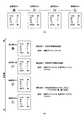
図5は、本発明の実施の形態におけるパラメータテーブル600の優先度を説明するための図である。図5(a)は、通信局#Aが受信要求を行っている場合の各通信局#A乃至#Dの現行パラメータテーブルの内容の一例を示している。本発明の実施の形態では、受信要求を行っている通信局#Aから離れるに従って、パラメータテーブルの優先度が下がるように設定されることを想定する。 FIG. 5 is a diagram for explaining the priorities of the parameter table 600 according to the embodiment of the present invention. FIG. 5A shows an example of the contents of the current parameter table of each of the communication stations #A to #D when the communication station #A makes a reception request. In the embodiment of the present invention, it is assumed that the priority of the parameter table is set so as to decrease as the distance from the communication station #A requesting reception increases.
そこで、図5(b)のように、自局が受信要求を行っている端末(通信局)の優先度を最も高い「優先度1」とする。この場合、要求元アドレス(SA)および送信元アドレス(FA)が共に自局アドレスに一致することが条件となる。 Therefore, as shown in FIG. 5B, the priority of the terminal (communication station) from which the local station is requesting reception is set to the highest “
また、隣接局が受信要求を行っている端末の優先度を次に高い「優先度2」とする。この場合、要求元アドレス(SA)および送信元アドレス(FA)は同一となるが、これらが自局アドレスに一致しないことが条件となる。 Further, the priority of the terminal to which the adjacent station is requesting reception is set to “
そして、「優先度1」または「優先度2」の何れにも該当しない端末は「優先度3」となるが、この「優先度3」を有するパラメータテーブル間の優劣は生存回数640によって判断される。すなわち、「優先度3」同士の場合には、生存回数640が大きい程優先度は高いものと解釈される。 A terminal that does not correspond to either “
従って、図5(a)の例では、図5(b)のように通信局#Aが「優先度1」、通信局#Bが「優先度2」となる。また、通信局#Cおよび#Dは共に「優先度3」であるが、生存回数640が大きい通信局#Cの方が通信局#Dよりも優先度は高いものとして扱われることになる。 Accordingly, in the example of FIG. 5A, the communication station #A has “
図6は、本発明の実施の形態におけるループバックの発生を説明するための図である。上述のような状態遷移を想定した場合、無条件に現行パラメータテーブルの更新を行うと、タイミングによっては以下のようなループバックを生じる可能性がある。 FIG. 6 is a diagram for explaining the occurrence of loopback in the embodiment of the present invention. Assuming the state transition as described above, if the current parameter table is updated unconditionally, the following loopback may occur depending on the timing.
通信局#Aから受信要求が行われることにより通信局#B乃至#Dの状態が強制設定状態10となった後、通信局#Bと通信局#Cの間および通信局#Bと通信局#Dの間の通信が途絶えた場合を想定する。このとき、タイミングの差異により通信局#Cだけが移行状態30に遷移していたと仮定して、通信局#Dから通信局#Cに対して強制モードフラグ610が有効を示すパラメータテーブルが送信されたとすると(図6(1))、通信局#Cは再び強制設定状態10に遷移する(図6(2))。 After the reception request is made from the communication station #A, the state of the communication stations #B to #D becomes the forced setting
その後、通信局#Dが移行状態30に遷移すると、今度は通信局#Cから通信局#Dに対して強制モードフラグ610が有効を示すパラメータテーブルが送信される(図6(3))。これにより、通信局#Dは再び強制設定状態10に遷移する(図6(4))。 Thereafter, when the communication station #D changes to the
このように、本来、強制解除状態20に遷移すべき通信局同士が遷移タイミングのずれによって強制設定状態10と移行状態30との間を行き来する現象をループバックと呼ぶ。本発明の実施の形態では、このループバックを未然に防止するために、移行状態30から強制設定状態10に遷移する際の条件(図4における条件5)において以下の判定条件を設ける。 As described above, a phenomenon in which communication stations that should originally transition to the forced
すなわち、現行パラメータテーブルの要求元アドレス(SA)と受信パラメータテーブルの要求元アドレス(SA)とを比較し、両者が異なる場合は、受信パラメータテーブルに基づいて現行パラメータテーブルを更新する。一方、両者の要求元アドレス(SA)が等しい場合には、さらにそれぞれのパラメータテーブルの優先度を比較し、現行パラメータテーブルの優先度のほうが受信パラメータテーブルの優先度よりも小さい場合に限り、受信パラメータテーブルに基づいて現行パラメータテーブルを更新する。 That is, the request source address (SA) of the current parameter table is compared with the request source address (SA) of the reception parameter table, and if they are different, the current parameter table is updated based on the reception parameter table. On the other hand, when both request source addresses (SA) are equal, the priorities of the respective parameter tables are further compared, and only when the priority of the current parameter table is lower than the priority of the reception parameter table, the reception is performed. Update the current parameter table based on the parameter table.
次に本発明の実施の形態における各無線通信装置における現行パラメータテーブルの更新例について説明する。 Next, an example of updating the current parameter table in each wireless communication apparatus in the embodiment of the present invention will be described.
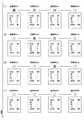
図7は、本発明の実施の形態における現行パラメータテーブルの第1の更新例を示す図である。この図では、線が施されている通信局同士が周辺局として直接無線通信を行うことができることを意味する。具体的には、通信局#Aと#B、#Bと#C、#Cと#Dが互いに直接的に無線通信を行うことができる。また、この図では、時間軸を縦方向にとり、上から下へいくにつれて時間が経過していく様子を表す。以下、現行パラメータテーブルの更新例を示す他の図においても同様である。 FIG. 7 is a diagram showing a first update example of the current parameter table in the embodiment of the present invention. In this figure, it means that communication stations provided with lines can directly perform wireless communication as peripheral stations. Specifically, the communication stations #A and #B, #B and #C, and #C and #D can directly perform wireless communication with each other. Further, in this figure, the time axis is taken in the vertical direction, and the time passes from the top to the bottom. The same applies to other drawings showing examples of updating the current parameter table.
まず、全ての通信局#A乃至#Dにおいて、現行パラメータテーブルがリセットされているものとする(図7(1))。すなわち、強制モードフラグ610が無効を示しており、これに対応して強制状態650は強制解除状態20にあるものとする。 First, it is assumed that the current parameter table is reset in all the communication stations #A to #D (FIG. 7 (1)). That is, the forced
ここで、通信局#Aが受信要求を行う場合、強制モードフラグ610を有効にし、強制状態650は強制設定状態10に遷移する。また、要求元アドレス620および送信元アドレス630は、ともに通信局#Aのアドレスとなる。また、生存回数640として、「2」が設定されたものと想定する(図7(2))。通信局#Aは、この現行パラメータテーブルを周辺局に送信する。 Here, when the communication station #A makes a reception request, the forced
通信局#Aからパラメータテーブルを受信した通信局#Bは、その受信したパラメータテーブルに基づいて現行パラメータテーブルを更新する。すなわち、強制モードフラグ610を有効にし、強制状態650は強制設定状態10に遷移する。また、要求元アドレス620および送信元アドレス630は、ともに通信局#Aのアドレスとなる。また、生存回数640には、受信時の「2」から「1」を減じた「1」が設定される(図7(3))。通信局#Bは、この現行パラメータテーブルを周辺局に送信する。 The communication station #B that has received the parameter table from the communication station #A updates the current parameter table based on the received parameter table. That is, the forced
通信局#Bからパラメータテーブルを受信した通信局#Cは、その受信したパラメータテーブルに基づいて現行パラメータテーブルを更新する。すなわち、強制モードフラグ610を有効にし、強制状態650は強制設定状態10に遷移する。また、要求元アドレス620は通信局#Aのアドレスであり、送信元アドレス630は通信局#Bのアドレスとなる。また、生存回数640には、受信時の「1」から「1」を減じた「0」が設定される(図7(4))。通信局#Cは、この現行パラメータテーブルを周辺局に送信する。 The communication station #C that has received the parameter table from the communication station #B updates the current parameter table based on the received parameter table. That is, the forced
なお、通信局#Bが現行パラメータテーブルをブロードキャスト送信により送信した場合には、そのパラメータテーブルを通信局#Aも受信することになる。このとき、通信局#Aは、現行パラメータテーブルの優先度と通信局#Bから送信されてきたパラメータテーブルの優先度とを比較し、現行パラメータテーブルの優先度のほうが通信局#Bから送信されてきたパラメータテーブルの優先度よりも高いので、現行パラメータテーブルを変更しない。 When communication station #B transmits the current parameter table by broadcast transmission, communication station #A also receives the parameter table. At this time, the communication station #A compares the priority of the current parameter table with the priority of the parameter table transmitted from the communication station #B, and the priority of the current parameter table is transmitted from the communication station #B. The current parameter table is not changed because it is higher than the priority of the parameter table.
通信局#Cからパラメータテーブルを受信した通信局#Dは、その受信したパラメータテーブルにおいて生存回数640が「0」を示していることから、現行パラメータテーブルの変更を行わない(図7(4))。 The communication station #D that has received the parameter table from the communication station #C does not change the current parameter table because the
図8は、本発明の実施の形態における現行パラメータテーブルの第2の更新例を示す図である。この図では、通信局#Aが受信要求を行ったことにより、通信局#Bおよび#Cが強制設定状態10に遷移している状態を想定している(図8(1))。 FIG. 8 is a diagram showing a second update example of the current parameter table in the embodiment of the present invention. In this figure, it is assumed that the communication stations #A and #C have transitioned to the forced setting
ここで、通信局#Aが受信要求を解除した場合、通信局#Aの現行パラメータテーブルがリセットされ、強制モードフラグ610が無効を示し、強制状態650が強制解除状態20となる(図8(2))。 When the communication station #A cancels the reception request, the current parameter table of the communication station #A is reset, the forced
通信局#Aからのパラメータテーブルを受信した通信局#Bは、その受信したパラメータテーブルに基づいて現行パラメータテーブルを更新する。すなわち、現行パラメータテーブルと受信パラメータテーブルの要求元アドレス620が一致し、かつ、受信パラメータテーブルの強制モードフラグ610が無効を表していることから、現行パラメータテーブルの強制状態650は移行状態30に遷移する(図8(2))。その後、通信局#Bは、一定期間内に他の通信局から強制モードフラグ610が有効を示すパラメータテーブルを受信しなかったことから、現行パラメータテーブルの強制状態650が強制解除状態20に遷移して、現行パラメータテーブルがリセットされる(図8(3))。 The communication station #B that has received the parameter table from the communication station #A updates the current parameter table based on the received parameter table. That is, since the
通信局#Bからのパラメータテーブルを受信した通信局#Cにおいても同様の手順で現行パラメータテーブルの更新が行われ、強制状態650が移行状態30に遷移した後に(図8(3))、さらに強制解除状態20に遷移する(図8(4))。 In the communication station #C that has received the parameter table from the communication station #B, the current parameter table is updated in the same procedure, and after the forced
図9は、本発明の実施の形態における現行パラメータテーブルの第3の更新例を示す図である。この例では、図7の場合と同様に、全ての通信局#A乃至#Dにおいて現行パラメータテーブルがリセットされている状態から(図9(1))、通信局#Aが受信要求を行った結果(図9(2))、通信局#Bおよび#Cが強制設定状態10となっているものとする。 FIG. 9 is a diagram showing a third update example of the current parameter table in the embodiment of the present invention. In this example, as in the case of FIG. 7, the communication station #A makes a reception request from the state where the current parameter table is reset in all the communication stations #A to #D (FIG. 9 (1)). As a result (FIG. 9B), it is assumed that the communication stations #B and #C are in the forced setting
ここで、さらに通信局#Dが受信要求を行う場合、強制モードフラグ610を有効にし、強制状態650は強制設定状態10に遷移する。また、要求元アドレス620および送信元アドレス630は、ともに通信局#Dのアドレスとなる。また、生存回数640として、「2」が設定されたものと想定する(図9(4))。 Here, when the communication station #D further makes a reception request, the forced
通信局#Dからパラメータテーブルを受信した通信局#Cは、その受信したパラメータテーブルの優先度と現行パラメータテーブルの優先度とを比較し、受信パラメータテーブルの優先度の方が高いことから、この受信パラメータテーブルに基づいて現行パラメータテーブルを更新する。すなわち、要求元アドレス620および送信元アドレス630は、ともに通信局#Dのアドレスとなる。また、生存回数640には、受信時の「2」から「1」を減じた「1」が設定される(図9(4))。 The communication station #C that has received the parameter table from the communication station #D compares the priority of the received parameter table with the priority of the current parameter table, and the priority of the reception parameter table is higher. Update the current parameter table based on the received parameter table. That is, both the
なお、その後、通信局#Bにおいて、通信局#Cより変更されたパラメータテーブルを受信することになるが、この場合、パラメータテーブルの優先度は通信局#Bの現行パラメータテーブルのほうが高いため、通信局#Bの現行パラメータテーブルが変更されることはない。 After that, the communication station #B receives the changed parameter table from the communication station #C. In this case, the priority of the parameter table is higher in the current parameter table of the communication station #B. The current parameter table of the communication station #B is not changed.
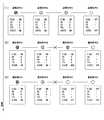
図10は、本発明の実施の形態における現行パラメータテーブルの第4の更新例を示す図である。この例では、図9のように通信局#Aおよび#Dの両者から受信要求が行われている状態を想定している(図10(1))。 FIG. 10 is a diagram showing a fourth update example of the current parameter table in the embodiment of the present invention. In this example, it is assumed that reception requests are made from both the communication stations #A and #D as shown in FIG. 9 (FIG. 10 (1)).
ここで、通信局#Dが受信要求を解除した場合、通信局#Dの現行パラメータテーブルがリセットされ、強制モードフラグ610が無効を示し、強制状態650が強制解除状態20となる(図10(2))。 Here, when the communication station #D cancels the reception request, the current parameter table of the communication station #D is reset, the forced
通信局#Dからのパラメータテーブルを受信した通信局#Cは、図8(2)で説明したように、強制状態650を移行状態30に遷移させる(図10(2))。その後、通信局#Cは、通信局#Bからのパラメータテーブルを受信し、その受信パラメータテーブルの要求元アドレス620が現行パラメータテーブルのものとは異なることから、受信パラメータテーブルに基づいて現行パラメータテーブルを更新する。すなわち、強制状態650が強制設定状態10に遷移する。また、要求元アドレス620は通信局#Aのアドレスであり、送信元アドレス630は通信局#Bのアドレスとなる。また、生存回数640には、受信時の「1」から「1」を減じた「0」が設定される(図10(3))。 Receiving the parameter table from the communication station #D, the communication station #C changes the forced
図11は、本発明の実施の形態における現行パラメータテーブルの第5の更新例を示す図である。この例では、図8と同様に、通信局#Aが受信要求を行ったことにより、通信局#Bおよび#Cが強制設定状態10に遷移している状態を想定している(図11(1))。 FIG. 11 is a diagram showing a fifth update example of the current parameter table in the embodiment of the present invention. In this example, as in FIG. 8, it is assumed that the communication stations #B and #C have transitioned to the forced setting
ここで、通信局#Bと#Cの間のパケット送受信がなんらかの理由によって不可能な状態となったと仮定する。その結果、通信局#Bより送信されていた受信要求が通信局#Cで受信できなくなり、一定期間が経過すると、通信局#Cは強制状態650を移行状態30に遷移させる(図11(2))。 Here, it is assumed that packet transmission / reception between the communication stations #B and #C has become impossible for some reason. As a result, the reception request transmitted from the communication station #B cannot be received by the communication station #C, and when a certain period of time elapses, the communication station #C changes the forced
その後、さらに一定期間が経過しても通信局#Bからの受信要求を受信しないため、通信局#Cは強制状態650を強制解除状態20に遷移させて、現行パラメータテーブルをリセットする(図11(3))。 After that, since a reception request from the communication station #B is not received even after a certain period of time has elapsed, the communication station #C changes the forced
図12は、本発明の実施の形態における現行パラメータテーブルの第6の更新例を示す図である。この例では、図8や図11と同様に、通信局#Aが受信要求を行ったことにより、通信局#Bおよび#Cが強制設定状態10に遷移している状態を想定している(図12(1))。 FIG. 12 is a diagram showing a sixth update example of the current parameter table in the embodiment of the present invention. In this example, as in FIG. 8 and FIG. 11, it is assumed that the communication stations #B and #C have transitioned to the forced setting
ここで、通信局#Aと#Bの間のパケット送受信がなんらかの理由によって不可能な状態となったと仮定する。その結果、通信局#Aより送信されていた受信要求が通信局#Bで受信できなくなり、一定期間が経過すると、通信局#Bは強制状態650を移行状態30に遷移させる(図12(2))。その後、さらに一定期間が経過しても通信局#Aからの受信要求を受信しないため、通信局#Bは強制状態650を強制解除状態20に遷移させて、現行パラメータテーブルをリセットする(図12(3))。 Here, it is assumed that packet transmission / reception between the communication stations #A and #B has become impossible for some reason. As a result, the reception request transmitted from the communication station #A cannot be received by the communication station #B, and the communication station #B changes the forced
通信局#Bからのパラメータテーブルを受信した通信局#Cは、その受信したパラメータテーブルの強制状態650が強制解除状態20となっていることから、現行パラメータテーブルの強制状態650を移行状態30に遷移させる(図12(3))。その後、一定期間が経過しても何れの通信局からも受信要求を受信しないため、通信局#Cは強制状態650を強制解除状態20に遷移させて、現行パラメータテーブルをリセットする(図12(4))。 The communication station #C that has received the parameter table from the communication station #B changes the forced
図13は、本発明の実施の形態における現行パラメータテーブルの第7の更新例を示す図である。この例では、これまでの例と異なり、通信#B乃至#Dが互いに直接無線通信できる位置に配置されていたと想定する。そして、通信局#Bと#Cの間および通信局#Bと#Dの間のパケット送受信がなんらかの理由によって不可能な状態となったと仮定する(図13(1))。 FIG. 13 is a diagram showing a seventh update example of the current parameter table in the embodiment of the present invention. In this example, unlike the previous examples, it is assumed that the communication #B to #D are arranged at positions where they can directly wirelessly communicate with each other. Then, it is assumed that packet transmission / reception between the communication stations #B and #C and between the communication stations #B and #D is impossible for some reason (FIG. 13 (1)).
その結果、通信局#Bより送信されていた受信要求が通信局#Cおよび#Dで受信できなくなり、一定期間が経過すると、通信局#Cおよび#Dは強制状態650を移行状態30に遷移させる(図13(2))。その後、さらに一定期間が経過しても通信局#Bからの受信要求を受信しないため、通信局#Cおよび#Dは強制状態650を強制解除状態20に遷移させて、現行パラメータテーブルをリセットする(図13(3))。 As a result, the reception request transmitted from the communication station #B cannot be received by the communication stations #C and #D, and the communication stations #C and #D transition from the forced
図14は、本発明の実施の形態における現行パラメータテーブルの第8の更新例を示す図である。この例では、図13と同様に、通信#B乃至#Dが互いに直接無線通信できる位置に配置されていたと想定する。そして、通信局#Bと#Dの間のパケット送受信がなんらかの理由によって不可能な状態となったと仮定する(図14(1))。 FIG. 14 is a diagram showing an eighth update example of the current parameter table in the embodiment of the present invention. In this example, as in FIG. 13, it is assumed that the communication #B to #D are arranged at positions where they can directly communicate with each other. Then, it is assumed that packet transmission / reception between the communication stations #B and #D has become impossible for some reason (FIG. 14 (1)).
その結果、通信局#Bより送信されていた受信要求が通信局#Dで受信できなくなり、一定期間が経過すると、通信局#Dは強制状態650を移行状態30に遷移させる(図14(1))。その後、さらに一定期間が経過しても通信局#Bからの受信要求を受信しないため、通信局#Dは強制状態650を強制解除状態20に遷移させて、現行パラメータテーブルをリセットする(図14(2))。 As a result, the reception request transmitted from the communication station #B cannot be received by the communication station #D, and the communication station #D changes the forced
その後、通信局#Dは、通信局#Cから強制モードフラグ610が有効を示すパラメータテーブルを受信することにより、その受信パラメータテーブルに基づいて現行パラメータテーブルを更新する。すなわち、強制モードフラグ610を有効にし、強制状態650は強制設定状態10に遷移する。また、要求元アドレス620は通信局#Aのアドレスであり、送信元アドレス630は通信局#Cのアドレスとなる。また、生存回数640には、受信時の「1」から「1」を減じた「0」が設定される(図14(3))。Thereafter, the communication station #D receives the parameter table indicating that the forced
このように、本発明の実施の形態においては、各無線通信装置が自局の現行パラメータテーブルを送信することによりパラメータテーブルが適宜伝播され、必要に応じて受信パラメータテーブルに基づいて現行パラメータテーブルの更新が行われる。ここで説明したパラメータテーブルの送信は、上述のようにユニキャストおよびブロードキャストの何れによっても実現可能である。次にこの伝播の態様について説明する。 As described above, in the embodiment of the present invention, each wireless communication apparatus transmits the current parameter table of its own station, so that the parameter table is appropriately propagated. If necessary, the current parameter table is updated based on the received parameter table. Updates are made. Transmission of the parameter table described here can be realized by either unicast or broadcast as described above. Next, the mode of propagation will be described.
図15は、本発明の実施の形態におけるパラメータテーブルの伝播の態様の一例を示す図である。通信局#Aから当初の生存回数640が「2」と設定された受信要求が行われることを想定する。 FIG. 15 is a diagram showing an example of a propagation mode of the parameter table in the embodiment of the present invention. It is assumed that a reception request is made from the communication station #A with the
まず、通信局#Aは、ブロードキャストによりパラメータテーブルを送信する場合には、周辺局である通信局#Bおよび#Cに対して一斉に送信を行う。また、ユニキャストにより送信を行う場合には、(図示しない)近隣リストに基づいて通信局#Bおよび#Cを特定して一つずつ送信を行う。通信局#Bおよび#Cでは、受信パラメータテーブルの生存回数640から「1」が減じられ、新たな生存回数640として「1」が設定される。 First, when transmitting the parameter table by broadcast, the communication station #A transmits all the communication stations #B and #C, which are peripheral stations, all at once. When transmitting by unicast, the communication stations #B and #C are specified based on a neighbor list (not shown) and transmitted one by one. In the communication stations #B and #C, “1” is subtracted from the
通信局#Bおよび#Cは、ブロードキャストによりパラメータテーブルを送信する場合には、周辺局である通信局#Aおよび#Cならびに通信局#Aおよび#Eに対してそれぞれ一斉に送信を行う。また、ユニキャストにより送信を行う場合には、(図示しない)近隣リストに基づいて通信局#Aおよび#Cならびに通信局#Aおよび#Eをそれぞれ特定して一つずつ送信を行う。通信局#Dおよび#Eでは、受信パラメータテーブルの生存回数640から「1」が減じられ、新たな生存回数640として「0」が設定される。なお、通信局#Aは、通信局#Bおよび#Cからパラメータテーブルを受信しても、その受信パラメータテーブルの優先度が現行パラメータテーブルの優先度よりも低いため、現行パラメータテーブルの更新は行わない。 When transmitting the parameter table by broadcast, the communication stations #B and #C simultaneously transmit to the communication stations #A and #C and the communication stations #A and #E, which are peripheral stations. When transmitting by unicast, the communication stations #A and #C and the communication stations #A and #E are specified based on a neighbor list (not shown) and transmitted one by one. In the communication stations #D and #E, “1” is subtracted from the
通信局#Dおよび#Eは、ブロードキャストによりパラメータテーブルを送信する場合には、周辺局である通信局#Bおよび#Fならびに通信局#Cおよび#Fに対してそれぞれ一斉に送信を行う。また、ユニキャストによる送信の場合には、生存回数640が「0」に設定されていることから、それ以上の送信は行われない。 When transmitting the parameter table by broadcasting, the communication stations #D and #E simultaneously transmit to the communication stations #B and #F and the communication stations #C and #F, which are peripheral stations. In the case of transmission by unicast, since the
通信局#Fは、通信局#Dおよび#Eからブロードキャストによりパラメータテーブルを受信した際、生存回数640が「0」であることから、現行パラメータテーブルの更新を行わない。また、それ以上の送信も行われない。なお、通信局#Bおよび#Cは、通信局#Dおよび#Eからブロードキャストによりパラメータテーブルを受信しても、その受信パラメータテーブルの優先度が現行パラメータテーブルの優先度よりも低いため、現行パラメータテーブルの更新は行わない。 The communication station #F does not update the current parameter table because the
このように、パラメータテーブルの送信は、ユニキャストおよびブロードキャストの何れによっても実現可能であることがわかる。 Thus, it can be seen that transmission of the parameter table can be realized by either unicast or broadcast.
次に本発明の実施の形態における無線通信装置の動作について図面を参照して説明する。 Next, the operation of the wireless communication apparatus according to the embodiment of the present invention will be described with reference to the drawings.
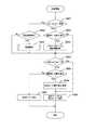
図16は、本発明の実施の形態における無線通信装置の全体の動作手順の一例を示す流れ図である。 FIG. 16 is a flowchart showing an example of the overall operation procedure of the wireless communication apparatus according to the embodiment of the present invention.
まず、無線通信装置の電源が投入されると(ステップS901)、その直後の処理として、現行パラメータテーブルの初期処理が実行される(ステップS902)。この初期処理の一例として、周辺局との認証処理が考えられる。周辺局との認証方法としては、何らかの形で事前に相手端末の存在を確認した後、周辺局と認証に関するパケット送受信を行うのが一般的である。例えば、無線通信装置間においてビーコンの送受信が行われ、そのビーコンの送受信によって互いの存在を認識した後、認証に関するパケットの送受信が開始される。 First, when the power of the wireless communication apparatus is turned on (step S901), an initial process of the current parameter table is executed as a process immediately after that (step S902). As an example of this initial process, an authentication process with a peripheral station can be considered. As an authentication method with a peripheral station, it is common to perform packet transmission / reception with the peripheral station after confirming the existence of the counterpart terminal in some form in advance. For example, transmission / reception of a beacon is performed between wireless communication devices, and transmission / reception of a packet related to authentication is started after recognizing each other's presence by transmission / reception of the beacon.
その際、相手装置の存在を認識した後、速やかに認証シーケンス動作に入るためには、両装置とも通常モードに入っていることが前提となる。つまり、相手装置が間欠モードである場合には、事前に相手装置に対して受信要求を行っておく必要がある。この場合、例えば、現行パラメータテーブルの初期値として、強制モードフラグ610を有効、要求元アドレス620および送信元アドレス630を自局アドレス、生存回数640を「1」、強制状態650を強制設定状態10とすることにより受信要求を行う。その後、認証する相手装置の存在確認に加えて、周辺局から受信されるパラメータテーブルより相手装置が強制モードに入っていることを確認できた後、認証シーケンス動作を開始することになる。 At that time, in order to immediately enter the authentication sequence operation after recognizing the existence of the counterpart device, it is assumed that both devices are in the normal mode. That is, when the counterpart device is in the intermittent mode, it is necessary to make a reception request to the counterpart device in advance. In this case, for example, as the initial value of the current parameter table, the forced
本発明の実施の形態における現行パラメータテーブルの更新処理は、大きく分けて、(1)周辺局からのパラメータテーブル受信時の更新処理、(2)定期的更新処理、(3)自局状況による更新処理、の3つの処理から成り立つ。これらの更新処理は、その無線通信装置の電源が切断されるまでの間、繰返し実行される。 The update process of the current parameter table in the embodiment of the present invention can be broadly divided into (1) update process when receiving a parameter table from a peripheral station, (2) periodic update process, and (3) update according to own station status. This process consists of three processes. These update processes are repeatedly executed until the power of the wireless communication apparatus is turned off.
周辺局からのパラメータテーブル受信時の更新処理として、無線通信装置は、周辺局である他の無線通信装置からパラメータテーブルを受信すると(ステップS903)、その受信パラメータテーブルに基づく更新処理を試行する(ステップS910)。その結果、現行パラメータテーブルの所定の更新が行われたか否かを示す更新フラグが設定される(ステップS920)。この更新フラグは、現行パラメータテーブルが一定時間更新されなかったタイムアウトを検出するために用いられる。 As an update process at the time of receiving a parameter table from a peripheral station, when the wireless communication apparatus receives a parameter table from another wireless communication apparatus that is a peripheral station (step S903), it tries an update process based on the received parameter table (step S903). Step S910). As a result, an update flag indicating whether or not a predetermined update of the current parameter table has been performed is set (step S920). This update flag is used to detect a timeout when the current parameter table has not been updated for a certain period of time.
次に定期的更新処理として、予め定められた更新周期タイミングが到来する度に(ステップS904)、現行パラメータテーブルの更新が試行される(ステップS930)。この定期的更新処理が行われた場合には、更新フラグは一旦リセットされる(ステップS905)。 Next, as a periodic update process, every time a predetermined update cycle timing arrives (step S904), an attempt is made to update the current parameter table (step S930). When this periodic update process is performed, the update flag is once reset (step S905).
また、自局状況による更新処理として、無線通信装置は、受信要求を行う場合やその受信要求を解除して強制モードを終了する場合に、現行パラメータテーブルの更新を行う(ステップS950)。 In addition, as an update process according to the local station status, the wireless communication apparatus updates the current parameter table when making a reception request or canceling the reception request to end the forced mode (step S950).
なお、この図16のさらに詳細な動作手順は図17乃至25に示されるが、これらの図において、現行パラメータテーブルは"ptbl_now"、受信パラメータテーブルは"ptbl_new"によりそれぞれ表される。また、それぞれのパラメータテーブルにおいて、強制モードフラグ610は"flag"、要求元アドレス620は"sa"、送信元アドレス630は"fa"、生存回数640は"ttl"、強制状態650は"state"によりそれぞれ表される。そして、これらの組合せにより、例えば、現行パラメータテーブルの強制状態650は"ptbl_now.state"などと表される。また、現行パラメータテーブルの優先度は"ptbl_now_priority"、受信パラメータテーブルの優先度は"ptbl_new_priority"によりそれぞれ表される。 The more detailed operation procedure of FIG. 16 is shown in FIGS. 17 to 25, in which the current parameter table is represented by “ptbl_now” and the reception parameter table is represented by “ptbl_new”. In each parameter table, the forced
図17は、本発明の実施の形態におけるパラメータテーブル応答更新(ステップS910)の動作手順の一例を示す流れ図である。 FIG. 17 is a flowchart showing an example of an operation procedure of the parameter table response update (step S910) in the embodiment of the present invention.
まず、この応答更新の前提として、受信パラメータテーブルの生存回数640が「0」の場合(ステップS911)や、受信パラメータテーブルの送信元アドレス630が自局アドレスである場合(ステップS912)には、更新の対象外とされる。 First, as a premise of this response update, when the
そして、受信パラメータテーブルの要求元アドレス620が送信局のアドレスと一致した場合には(ステップS913)その受信パラメータテーブルの優先度として「優先度2」を表す"PARAM_NEIGHBOR"を設定し(ステップS914)、そうでない場合には受信パラメータテーブルの優先度として「優先度3」を表す"PARAM_OTHER"を設定する(ステップS915)。 If the
その後、現行パラメータテーブルの強制状態650が強制解除状態20であれば(ステップS916)"OFF"時のパラメータテーブル登録処理(ステップS970)を、現行パラメータテーブルの強制状態650が強制設定状態10であれば(ステップS917)"ON"時のパラメータテーブル登録処理(ステップS990)を、または、現行パラメータテーブルの強制状態650が移行状態30であれば"MOV"時のパラメータテーブル登録処理(ステップS980)をそれぞれ実行する。 Thereafter, if the forced
図18は、本発明の実施の形態における強制解除状態のパラメータテーブル登録処理(ステップS970)の動作手順の一例を示す流れ図である。ここでは、現行パラメータテーブルの強制状態650が強制解除状態20のときに、受信パラメータテーブルが強制設定状態10を示していれば(ステップS971)、パラメータテーブル更新処理が行われる(ステップS972)。 FIG. 18 is a flowchart showing an example of an operation procedure of the parameter table registration process (step S970) in the forced release state according to the embodiment of the present invention. Here, if the reception parameter table indicates the forced setting
図19は、本発明の実施の形態におけるパラメータテーブル更新処理(ステップS972)の動作手順の一例を示す流れ図である。ここでは、受信パラメータテーブルに基づいて現行パラメータテーブルの更新が行われる。 FIG. 19 is a flowchart showing an example of the operation procedure of the parameter table update process (step S972) in the embodiment of the present invention. Here, the current parameter table is updated based on the received parameter table.
すなわち、現行パラメータテーブルの強制モードフラグ610は有効を示すものに設定される(ステップS811)。また、現行パラメータテーブルの要求元アドレス620には受信パラメータテーブルの要求元アドレス620が設定され(ステップS812)、現行パラメータテーブルの送信元アドレス630には受信パラメータテーブルの送信局アドレスが設定される(ステップS813)。 That is, the forced
さらに、現行パラメータテーブルの生存回数640としては、受信パラメータテーブルの生存回数640から「1」を減じたものが設定される(ステップS814)。また、現行パラメータテーブルの強制状態650として強制設定状態10が設定される(ステップS815)。 Further, the number of
図20は、本発明の実施の形態における移行状態のパラメータテーブル登録処理(ステップS980)の動作手順の一例を示す流れ図である。この場合の登録処理は、受信パラメータテーブルの強制状態650が強制設定状態を示すものに限られるため、それ以外の場合には対象外とされる(ステップS981)。 FIG. 20 is a flowchart showing an example of the operation procedure of the transition state parameter table registration process (step S980) according to the embodiment of the present invention. Since the registration process in this case is limited to that in which the forced
現行パラメータテーブルの要求元アドレス620と受信パラメータテーブルの要求元アドレス620とが一致しない場合には(ステップS982)、新たな受信要求処理であると考えられるため、パラメータテーブル更新処理が行われる(ステップS988)。なお、このパラメータテーブル更新処理(ステップS988)は、図19で説明したパラメータテーブル更新処理と同様である。 If the
現行パラメータテーブルの要求元アドレス620と受信パラメータテーブルの要求元アドレス620とが一致する場合において(ステップS983)、現行パラメータテーブルの送信元アドレス630と受信パラメータテーブルの送信局アドレスとが一致するときには、受信要求が継続されている可能性が高いものと考えられるため、パラメータテーブル更新処理が行われる(ステップS988)。 When the
それ以外の場合、パラメータテーブルの優先度に応じてパラメータテーブル更新処理を行うか否かが判断される。すなわち、受信パラメータテーブルの優先度が現行パラメータテーブルの優先度よりも高い場合には(ステップS984)、パラメータテーブル更新処理が行われる(ステップS988)。また、両者の優先度が等しい場合には(ステップS985)、その優先度が「優先度3」であって(ステップS986)、かつ、受信パラメータテーブルの生存回数640から「1」を減じた値が現行パラメータテーブルの生存回数640よりも高ければ(ステップS987)、やはりパラメータテーブル更新処理が行われる(ステップS988)。 In other cases, it is determined whether or not to perform the parameter table update process according to the priority of the parameter table. That is, when the priority of the reception parameter table is higher than the priority of the current parameter table (step S984), the parameter table update process is performed (step S988). Further, when the priorities of both are equal (step S985), the priority is “
図21は、本発明の実施の形態における強制設定状態のパラメータテーブル登録処理(ステップS990)の動作手順の一例を示す流れ図である。この場合の登録処理は、受信パラメータテーブルの強制状態650が強制設定状態10を示すものに限られるため、それ以外の場合には対象外とされる(ステップS991)。但し、受信パラメータテーブルの強制状態650が強制解除状態20で(ステップS997)、かつ、現行パラメータテーブルの送信元アドレス630が受信パラメータテーブルの送信局アドレスと同じあれば(ステップS998)、強制モードの解除が指示されたものとして、現行パラメータテーブルの強制状態650を移行状態30に遷移させる(ステップS999)。 FIG. 21 is a flowchart illustrating an example of an operation procedure of the parameter table registration process (step S990) in the forced setting state according to the embodiment of the present invention. Since the registration process in this case is limited to the reception parameter table in which the forced
受信パラメータテーブルの強制状態650が強制設定状態10であれば(ステップS991)、パラメータテーブルの優先度に応じてパラメータテーブル更新処理を行うか否かが判断される。すなわち、受信パラメータテーブルの優先度が現行パラメータテーブルの優先度よりも高い場合には(ステップS992)、パラメータテーブル更新処理が行われる(ステップS996)。また、両者の優先度が等しい場合には(ステップS993)、その優先度が「優先度3」であって(ステップS994)、かつ、受信パラメータテーブルの生存回数640から「1」を減じた値が現行パラメータテーブルの生存回数640よりも高ければ(ステップS995)、やはりパラメータテーブル更新処理が行われる(ステップS996)。なお、このパラメータテーブル更新処理(ステップS996)は、図19で説明したパラメータテーブル更新処理と同様である。 If the forced
図22は、本発明の実施の形態における更新フラグ設定処理(ステップS920)の動作手順の一例を示す流れ図である。この更新フラグ設定処理では、受信パラメータテーブルの強制モードフラグ610が有効であり(ステップS921)、受信パラメータテーブルの要求元アドレス620と現行パラメータテーブルの要求元アドレス620が一致し(ステップS922)、かつ、現行パラメータテーブルの送信元アドレス630が受信パラメータテーブルの送信局アドレスと一致する場合に(ステップS923)、更新フラグが「更新有」に設定される(ステップS924)。なお、図中、更新フラグを"update_ptbl_flag"と表している。 FIG. 22 is a flowchart showing an example of the operation procedure of the update flag setting process (step S920) in the embodiment of the present invention. In this update flag setting process, the
図23は、本発明の実施の形態におけるパラメータテーブル定期更新処理(ステップS930)の動作手順の一例を示す流れ図である。 FIG. 23 is a flowchart showing an example of an operation procedure of the parameter table periodic update process (step S930) in the embodiment of the present invention.
まず、この定期更新の前提として、現行パラメータテーブルの要求元アドレス620が自局アドレスの場合(ステップS931)や、現行パラメータテーブルの強制状態650が強制解除状態20である場合(ステップS932)には、更新の対象外とされる。なお、現行パラメータテーブルの要求元アドレス620が自局アドレスの場合には、次に説明する自発更新(ステップS950)の対象となる。 First, as a premise of this periodic update, when the
そして、現行パラメータテーブルが一定期間更新されていないことを検出するために、更新フラグの状態に基づいて不更新カウンタを設定する。すなわち、更新フラグが「更新有」を示している場合には(ステップS933)不更新カウンタは「0」にリセットされ(ステップS934)、更新フラグが「更新無」を示している場合には不更新カウンタはカウントアップする(ステップS935)。なお、図中、不更新カウンタを"count_not_update"と表している。 Then, in order to detect that the current parameter table has not been updated for a certain period, a non-update counter is set based on the state of the update flag. That is, when the update flag indicates “update available” (step S933), the non-update counter is reset to “0” (step S934), and when the update flag indicates “no update”, The update counter counts up (step S935). In the figure, the non-update counter is represented as “count_not_update”.
現行パラメータテーブルの強制状態650が強制設定状態10において(ステップS936)、不更新カウンタが所定の閾値(TH_ON_TO_MOV)以上となっていれば(ステップS937)、強制設定状態10がタイムアウトしたものとして、現行パラメータテーブルの強制状態650を移行状態30に遷移させる(ステップS938)。また、現行パラメータテーブルの強制状態650が移行状態30において(ステップS936)、不更新カウンタが所定の閾値(TH_MOV_TO_OFF)以上となっていれば(ステップS939)、移行状態30がタイムアウトしたものとして、現行パラメータテーブルの内容がリセットされ、現行パラメータテーブルの強制状態650を強制解除状態20に遷移させる(ステップS941)。その後、不更新カウンタは「0」にリセットされる(ステップS942)。 When the forced
図24は、本発明の実施の形態におけるパラメータテーブル自発更新処理(ステップS950)の動作手順の一例を示す流れ図である。 FIG. 24 is a flowchart illustrating an example of an operation procedure of the parameter table spontaneous update process (step S950) according to the embodiment of the present invention.
現行パラメータテーブルの要求元アドレス620が自局アドレスの場合において(ステップS951)、自局からの受信要求を解除して強制モードを終了させるときには(ステップS952)、現行パラメータテーブルの内容をリセットする(ステップS953)。これにより、現行パラメータテーブルの強制状態650は強制解除状態20に遷移する。 When the
また、現行パラメータテーブルの要求元アドレス620が自局アドレス以外の場合において(ステップS951)、自局から受信要求を実行するときには(ステップS954)、現行パラメータテーブルの各項目にそれぞれ値を設定する(ステップS820)。 Further, when the
その結果、現行パラメータテーブルの強制モードフラグ610が無効となっていれば(ステップS955)、強制モードを解除する。すなわち、電力モード制御部160における制御に従って、通常モードまたは間欠モードの何れかの電力モードとなる(ステップS959)。 As a result, if the forced
一方、現行パラメータテーブルの強制モードフラグ610が有効となっていれば(ステップS955)、電力モードは原則として強制モードへ移行する(ステップS957)。但し、例えば、自局がバッテリー駆動している端末であって長時間の常時送受信動作を行うことが困難な場合等、何らかの理由により強制モードへの移行を禁止しているような場合には(ステップS956)、強制モードへの移行を禁止するための処理が行われ(ステップS958)、電力モード制御部160における制御に従って、通常モードまたは間欠モードの何れかの電力モードとなる(ステップS959)。 On the other hand, if the forced
なお、このような強制モードへの移行禁止は、そのためのフラグをユーザが手動で設定するようにしてもよく、また、無線通信装置が自動的に設定するようにしてもよい。また、強制モードへの移行を禁止するための処理(ステップS958)としては、例えば、現行パラメータテーブルの生存回数640を「0」に設定することにより、自局を中継局としてさらに周辺局に受信要求を行うことを停止させること等が考えられる。 Such a prohibition of the transition to the forced mode may be set manually by the user, or may be automatically set by the wireless communication apparatus. As a process for prohibiting the transition to the forced mode (step S958), for example, by setting the
図25は、本発明の実施の形態における受信要求処理(ステップS820)の動作手順の一例を示す流れ図である。ここでは、受信要求を行うために新たに現行パラメータテーブルの設定が行われる。 FIG. 25 is a flowchart showing an example of the operation procedure of the reception request process (step S820) in the embodiment of the present invention. Here, the current parameter table is newly set in order to make a reception request.
すなわち、現行パラメータテーブルの強制モードフラグ610は有効を示すものに設定される(ステップS821)。また、現行パラメータテーブルの要求元アドレス620および送信元アドレス630には自局アドレスが設定される(ステップS822、S823)。 That is, the forced
さらに、現行パラメータテーブルの生存回数640としては、その初期値から「1」を減じたものが設定される(ステップS824)。また、現行パラメータテーブルの強制状態650として強制設定状態10が設定される(ステップS825)。そして、その現行パラメータテーブルの優先度としては最上位である「優先度1」が設定される(ステップS826)。 Further, the number of times of
なお、受信要求を実行するタイミングの一例としては、アドホックネットワークにおいて、AODV(Adhoc On-Demand Distance Vector)等に代表されるブロードキャストパケット送信が必要となるルーティングプロトコルシーケンスが実行されるときが該当する。経路検索では、RREQパケットと呼ばれるブロードキャストパケットを用いたフラッディング技術が適用されるが、その際、経路検索対象となるネットワーク内において間欠モードの装置が存在する場合にはブロードキャストパケットを受信できない装置が増加する。その結果、ルーティングプロトコルとして想定される経路とは異なる経路が形成され、また、経路が形成されるのに要する時間が増大するおそれが生じ得る。このとき、経路検索対象となるネットワーク内の装置に対して受信要求を行うことによって、ネットワーク内の全ての装置を一時的に送受信可能状態へ移行させて、ブロードキャストパケットを強制的に受信させることができる。 An example of the timing for executing the reception request corresponds to the case where a routing protocol sequence that requires broadcast packet transmission such as AODV (Adhoc On-Demand Distance Vector) is executed in an ad hoc network. In the route search, a flooding technique using a broadcast packet called an RREQ packet is applied. At that time, if there are devices in the intermittent mode in the network to be searched for, the number of devices that cannot receive the broadcast packet increases. To do. As a result, a route different from the route assumed as the routing protocol is formed, and there is a possibility that the time required for forming the route may increase. At this time, it is possible to forcibly receive broadcast packets by temporarily making all the devices in the network ready for transmission / reception by making a reception request to the devices in the network to be searched for routes. it can.
このように、本発明の実施の形態によれば、自律分散型の無線ネットワークにおいて、周辺局を常時送受信可能な状態へ強制的に移行させることができる。すなわち、自律分散的な処理によりネットワーク内において常時送受信可能状態あるいは間欠動作状態を任意の時間区間で作り出すことができる。これにより、間欠動作状態にある装置間においてフラッディング技術を容易に適用することが可能となる。例えば、自律分散型のメッシュ型アドホックネットワークにおける経路形成の遅延を改善することができる。 As described above, according to the embodiment of the present invention, it is possible to forcibly shift a peripheral station to a state in which transmission and reception are possible at all times in an autonomous distributed wireless network. That is, it is possible to create a continuous transmission / reception enabled state or an intermittent operation state in an arbitrary time interval in the network by autonomous distributed processing. As a result, the flooding technique can be easily applied between apparatuses in an intermittent operation state. For example, a delay in route formation in an autonomous distributed mesh ad hoc network can be improved.
また、制御情報のやり取りに関して、装置間におけるユニキャストパケットによる制御パケット等の送受信だけではなく、従来の無線通信ネットワークで用いられる情報報知用のブロードキャストパケット(例えば、ビーコン)を利用することも可能である。これにより、専用の制御パケット等を用いる方法に比べてオーバーヘッドを増やすことなく、周辺局を常時送受信可能な状態へ強制的に移行させることができる。また、既存のパケットを利用することが可能であることから、従来の無線通信システムとある程度の互換性を維持することが可能である。 Regarding the exchange of control information, it is possible to use not only transmission / reception of control packets and the like by unicast packets between devices but also broadcast packets (for example, beacons) for information notification used in conventional wireless communication networks. is there. As a result, it is possible to forcibly shift the peripheral station to a state where transmission and reception are possible at all times without increasing overhead as compared with a method using a dedicated control packet or the like. In addition, since existing packets can be used, it is possible to maintain a certain degree of compatibility with conventional wireless communication systems.
また、本発明の実施の形態では、直接通信可能な装置間の通信で足りるため、比較的単純な方法により周辺局を常時送受信可能な状態へ強制的に移行させることが可能であることから、余剰なオーバーヘッドの増加を抑えることができる。 In the embodiment of the present invention, since communication between devices capable of direct communication is sufficient, it is possible to forcibly shift a peripheral station to a state in which transmission and reception can be performed constantly by a relatively simple method. An increase in excess overhead can be suppressed.
特に、本発明の実施の形態では、各装置における自律分散的な処理によって、隣接局だけでなく、数ホップ先の周辺局を常時送受信可能な状態へ強制的に移行させることが可能であり、しかも強制的に常時送受信可能状態へ移行させるネットワークをホップ数によって制限することが可能である。これにより、不必要に周辺局を常時受信可能な状態へ移行させることがなく、ネットワーク全体での無駄な電力消費を抑制することができる。 In particular, in the embodiment of the present invention, it is possible to forcibly shift not only the neighboring station but also a peripheral station several hops ahead to a state where transmission and reception can be performed constantly by autonomous distributed processing in each device, In addition, it is possible to limit the network forcibly shifting to a state in which transmission / reception is always possible by the hop count. As a result, unnecessary power consumption in the entire network can be suppressed without unnecessarily shifting to a state in which peripheral stations can always be received.
そして、本発明の実施の形態では、各装置においてパラメータテーブルを管理して周辺局へ通知する。このようにパラメータテーブルを利用することにより、周辺局との整合性を保ちながら自律分散的な送受信動作の管理が可能となる。その際、各装置において管理するパラメータテーブルは、その装置から見た接続リンク数分ではなく、1つだけ保有しておけば足りるため、周辺局数の増加に伴うメモリ資源の枯渇等の問題はない。また、周辺局に対しても1つのパラメータテーブルだけを通知するため、無駄な通知処理の増加を抑えることができる。 In the embodiment of the present invention, the parameter table is managed in each device and notified to the peripheral station. By using the parameter table in this way, it is possible to manage autonomously distributed transmission / reception operations while maintaining consistency with peripheral stations. At that time, the parameter table managed in each device is not limited to the number of connection links seen from the device, but it is sufficient to have only one, so there are no problems such as memory resource depletion due to the increase in the number of peripheral stations. Absent. In addition, since only one parameter table is notified to the peripheral stations, an increase in useless notification processing can be suppressed.
なお、本発明の実施の形態は本発明を具現化するための一例を示したものであり、以下に示すように特許請求の範囲における発明特定事項とそれぞれ対応関係を有するが、これに限定されるものではなく本発明の要旨を逸脱しない範囲において種々の変形を施すことができる。 The embodiment of the present invention is an example for embodying the present invention and has a corresponding relationship with the invention-specific matters in the claims as shown below, but is not limited thereto. However, various modifications can be made without departing from the scope of the present invention.
すなわち、請求項1において、電力モード制御手段は例えば電力モード制御部160に対応する。また、強制情報保持手段は例えば現行パラメータテーブル保持手段110に対応する。また、強制情報送信手段は例えば送信部120に対応する。また、強制情報受信手段は例えば受信部130に対応する。また、強制情報更新制御手段は例えばパラメータテーブル更新制御部150に対応する。
That is , in
また、請求項6において、受信更新手段は例えば受信更新部151に対応する。 Further, in claim 6, the reception update means corresponds to the
また、請求項7または10における強制情報の状態として、第1の状態は例えば強制設定状態10に対応し、第2の状態は例えば強制解除状態20に対応し、第3の状態は例えば移行状態30に対応する。 Further, as the state of forced information in
また、請求項9において、定期更新手段は例えば定期更新部152に対応する。 Further, in claim 9, the periodic update means corresponds to, for example, the
また、請求項11または12において、無線通信の範囲内に存在する他の無線通信装置から当該他の無線通信装置における強制情報を受信する手順は例えばステップS903に対応する。また、強制情報保持手段に保持された強制情報と他の無線通信装置における強制情報との比較に基づいて強制情報保持手段に保持された強制情報を更新する手順は例えばステップS910に対応する。また、更新された強制情報を他の無線通信装置に送信する手順は例えば送信部120による処理に対応する。 Further, in claim 11 or 12, a procedure for receiving forced information in another wireless communication device from another wireless communication device existing within the wireless communication range corresponds to, for example, step S <b> 903. The procedure for updating the forced information held in the forced information holding means based on the comparison between the forced information held in the forced information holding means and the forced information in another wireless communication apparatus corresponds to, for example, step S910. The procedure for transmitting the updated forced information to another wireless communication apparatus corresponds to the processing by the
なお、本発明の実施の形態において説明した処理手順は、これら一連の手順を有する方法として捉えてもよく、また、これら一連の手順をコンピュータに実行させるためのプログラム乃至そのプログラムを記憶する記録媒体として捉えてもよい。 The processing procedure described in the embodiment of the present invention may be regarded as a method having a series of these procedures, and a program for causing a computer to execute these series of procedures or a recording medium storing the program May be taken as
10 強制設定状態(ON)
20 強制解除状態(OFF)
30 移行状態(MOV)
100、200、300 無線通信装置
109 アンテナ
110 現行パラメータテーブル保持部
120 送信部
130 受信部
140 受信パラメータテーブル保持部
150 パラメータテーブル更新制御部
151 受信更新部
152 定期更新部
153 自発更新部
160 電力モード制御部
600 パラメータテーブル
610 強制モードフラグ(FLAG)
620 要求元アドレス(SA)
630 送信元アドレス(FA)
640 生存回数(TTL)
650 強制状態(STATE)
10 Forced setting status (ON)
20 Forced release state (OFF)
30 Transition status (MOV)
100, 200, 300
620 Requester address (SA)
630 Source address (FA)
640 Number of Survival (TTL)
650 Forced state (STATE)
Claims (12)
Translated fromJapanese当該無線通信装置内に供給される電力の電力モードとして常時送受信動作が可能な状態にある通常モードと送受信動作を全く行わない状態を間欠的に混在させる間欠モードとを制御する電力モード制御手段と、
前記通常モードまたは前記間欠モードの何れにかかわらず強制的に送受信動作が可能な状態にさせる強制動作指示の有効または無効を示す強制モードフラグを含む強制情報を保持する強制情報保持手段と、
前記強制情報を無線通信の範囲内に存在する他の無線通信装置に送信する強制情報送信手段と、
前記他の無線通信装置から当該他の無線通信装置における強制情報を受信する強制情報受信手段と、
前記強制情報保持手段に保持された強制情報と前記他の無線通信装置における強制情報との比較に基づいて前記強制情報保持手段に保持された強制情報を更新する強制情報更新制御手段と
を具備する無線通信装置。In a wireless communication apparatus that performs communication with at least one relay station with a partner station that exists outside the range of wireless communication,
A power mode control meansfor controlling a normal mode in a state in which a transmission / reception operation is always possible and an intermittent mode in which a transmission / reception operation is not performed at all, as apower mode ofpower supplied to the wireless communication device; ,
And enforcement information holding means for holding the force information includingthe normal mode or forced Modofuragrayed indicating valid or invalid of forced operation instructionto the state capable of forcibly sending and receiving operation regardless any of the intermittent mode,
Forcing information transmitting means for transmitting the forcing information to another radio communication device existing within a radio communication range;
Forced information receiving means for receiving forced information in the other wireless communication device from the other wireless communication device;
Forcing information update control means for updating the forcing information held in the forcing information holding means based on a comparison between the forcing information held in the forcing information holding means and the forcing information in the other wireless communication device.No line communication apparatusthat.
前記強制情報送信手段は、前記生存回数が前記制限に達している場合には前記他の無線通信装置への送信を行わない The compulsory information transmission means does not perform transmission to the other wireless communication device when the number of times of survival has reached the limit.
請求項1記載の無線通信装置。The wireless communication apparatus according to claim 1.
請求項1記載の無線通信装置。The forced information update control means,Ru includes a receiving updating means for updating the forced information held in the forced information holding means based on force information in the another wireless communication apparatus when a predetermined condition is satisfied
The wireless communications apparatus of請 Motomeko1 wherein.
前記受信更新手段は、前記他の無線通信装置における強制情報の状態が前記第1の状態である場合には所定条件下で前記他の無線通信装置における強制情報に基づいて前記強制情報保持手段に保持された強制情報を更新する
請求項6記載の無線通信装置。The compulsory information held in the compulsory information holding means is a first state in which the compulsory operation instruction is valid by the compulsory mode flag, and the compulsory operation instruction is instructed by the compulsory mode flag. And further including any one of a second state that is invalidated and a third state that is in a transition stage from the first state to the second state,
The reception update unit is configured to transfer the forced information to the forced information holding unit based on the forced information in the other wireless communication device under a predetermined condition when the forced information state in the other wireless communication device is the first state.to update the compulsory information, which is held
The wireless communications apparatus of請 Motomeko 6 wherein.
請求項7記載の無線通信装置。The reception update means is predetermined if the state of forced information held in the forced information holding means is the first state and the forced information state in the other wireless communication apparatus is the second state. the state of the forced information held in the forced information holding meansRu to transition to the third state under
The wireless communications apparatus of請 Motomeko 7 wherein.
請求項6記載の無線通信装置。The forced information update control means periodically updates the forced information held in the forced information holding means under a predetermined condition when the forced information held in the forced information holding means is not updated by the reception update means for a predetermined period.Ru, further comprising the update means
The wireless communications apparatus of請 Motomeko 6 wherein.
前記定期更新手段は、前記強制情報保持手段に保持された強制情報の状態が前記第1の状態である場合に所定期間更新されなければ前記強制情報保持手段に保持された強制情報の状態を前記第3の状態に遷移させ、前記強制情報保持手段に保持された強制情報の状態が前記第3の状態である場合に所定期間更新されなければ前記第2の状態に遷移させる
請求項9記載の無線通信装置。The compulsory information held in the compulsory information holding means is a first state in which the compulsory operation instruction is valid by the compulsory mode flag, and the compulsory operation instruction is instructed by the compulsory mode flag. And further including any one of a second state that is invalidated and a third state that is in a transition stage from the first state to the second state,
If the state of the forced information held in the forced information holding unit is the first state, the periodic update unit changes the state of the forced information held in the forced information holding unit unless updated for a predetermined period. to transition to the third state,Ru to transition to the second state unless a predetermined period of time updated when the state of the forced information held in the forced information holding means is the third state
The wireless communications apparatus of請 Motomeko 9 wherein.
無線通信の範囲内に存在する他の無線通信装置から当該他の無線通信装置における強制情報を受信する手順と、
前記強制情報保持手段に保持された強制情報と前記他の無線通信装置における強制情報との比較に基づいて前記強制情報保持手段に保持された強制情報を更新する手順と、
前記更新された強制情報を前記他の無線通信装置に送信する手順と
を具備する制御方法。A wireless communication apparatus that performs communication with at least one relay station with a partner station that is outside the range of wireless communication, and aconstant transmission / reception operation is performed as apower mode ofpower supplied to the wireless communication apparatus. Power mode control meansfor controlling a normal mode in a possible state and an intermittent mode in which a state in which no transmission / reception operation is performed is intermittently mixed, and aforced transmission / reception operation regardless of the normal mode or the intermittent mode in the radio communication device and a forced information holding means for holding the force informationincluding forced Modofuragrayed indicating valid or invalid of forced operation instructionto the possible state,
A procedure for receiving compulsory information in another wireless communication device from another wireless communication device existing within the range of wireless communication;
Updating the forced information held in the forced information holding means based on a comparison between the forced information held in the forced information holding means and the forced information in the other wireless communication device;
The updated procedure tothat control method comprising the the force information to transmit to the other wireless communication device.
無線通信の範囲内に存在する他の無線通信装置から当該他の無線通信装置における強制情報を受信する手順と、
前記強制情報保持手段に保持された強制情報と前記他の無線通信装置における強制情報との比較に基づいて前記強制情報保持手段に保持された強制情報を更新する手順と、
前記更新された強制情報を前記他の無線通信装置に送信する手順と
をコンピュータに実行させるプログラム。A wireless communication apparatus that performs communication with at least one relay station with a partner station that is outside the range of wireless communication, and aconstant transmission / reception operation is performed as apower mode ofpower supplied to the wireless communication apparatus. Power mode control meansfor controlling a normal mode in a possible state and an intermittent mode in which a state in which no transmission / reception operation is performed is intermittently mixed, and aforced transmission / reception operation regardless of the normal mode or the intermittent mode in the radio communication device and a forced information holding means for holding the force informationincluding forced Modofuragrayed indicating valid or invalid of forced operation instructionto the possible state,
A procedure for receiving compulsory information in another wireless communication device from another wireless communication device existing within the range of wireless communication;
Updating the forced information held in the forced information holding means based on a comparison between the forced information held in the forced information holding means and the forced information in the other wireless communication device;
The updated enforcement information to execute a procedure to be transmitted to the other wireless communication device to the computerHelp program.
Priority Applications (2)
| Application Number | Priority Date | Filing Date | Title |
|---|---|---|---|
| JP2005139172AJP4701824B2 (en) | 2005-05-11 | 2005-05-11 | Wireless communication apparatus and control method thereof |
| US11/381,330US7664538B2 (en) | 2005-05-11 | 2006-05-02 | Wireless communication device and control method for the device |
Applications Claiming Priority (1)
| Application Number | Priority Date | Filing Date | Title |
|---|---|---|---|
| JP2005139172AJP4701824B2 (en) | 2005-05-11 | 2005-05-11 | Wireless communication apparatus and control method thereof |
Publications (2)
| Publication Number | Publication Date |
|---|---|
| JP2006319586A JP2006319586A (en) | 2006-11-24 |
| JP4701824B2true JP4701824B2 (en) | 2011-06-15 |
Family
ID=37463246
Family Applications (1)
| Application Number | Title | Priority Date | Filing Date |
|---|---|---|---|
| JP2005139172AExpired - Fee RelatedJP4701824B2 (en) | 2005-05-11 | 2005-05-11 | Wireless communication apparatus and control method thereof |
Country Status (2)
| Country | Link |
|---|---|
| US (1) | US7664538B2 (en) |
| JP (1) | JP4701824B2 (en) |
Families Citing this family (18)
| Publication number | Priority date | Publication date | Assignee | Title |
|---|---|---|---|---|
| US8745184B1 (en)* | 2007-05-18 | 2014-06-03 | Jasper Wireless, Inc. | Wireless communication provisioning using state transition rules |
| US9307397B2 (en) | 2005-04-29 | 2016-04-05 | Jasper Technologies, Inc. | Method for enabling a wireless device with customer-specific services |
| JP4701824B2 (en)* | 2005-05-11 | 2011-06-15 | ソニー株式会社 | Wireless communication apparatus and control method thereof |
| JP2007081579A (en)* | 2005-09-12 | 2007-03-29 | Canon Inc | COMMUNICATION DEVICE AND ITS CONTROL METHOD |
| MX2009011766A (en)* | 2007-04-30 | 2010-01-14 | Interdigital Tech Corp | A HOME (e)NODE-B WITH NEW FUNCTIONALITY. |
| CN101682543B (en) | 2007-06-04 | 2012-10-10 | 索尼株式会社 | Communication system, communication device, communication method |
| EP2148541B1 (en)* | 2008-07-21 | 2011-09-07 | Alcatel Lucent | Method for switching a client terminal from an idle mode to an active mode |
| EP2393316A4 (en)* | 2009-01-29 | 2017-04-26 | Fujitsu Limited | Wireless communication system |
| KR101572267B1 (en)* | 2009-06-25 | 2015-11-26 | 삼성전자주식회사 | System and method for mutual authentication between node and sink in the sensor network |
| JP4977221B2 (en)* | 2010-02-24 | 2012-07-18 | 株式会社バッファロー | Wireless LAN system, wireless LAN device and program thereof |
| JP5618243B2 (en)* | 2011-03-25 | 2014-11-05 | 株式会社国際電気通信基礎技術研究所 | Control device, program executed in the control device, and communication system including the control device |
| CN102267479B (en)* | 2011-05-16 | 2013-04-24 | 铁道部运输局 | Station autonomous machine for centralized traffic control system |
| WO2015139026A2 (en) | 2014-03-14 | 2015-09-17 | Go Tenna Inc. | System and method for digital communication between computing devices |
| CN105278379B (en)* | 2015-10-30 | 2018-02-23 | 中国铁道科学研究院通信信号研究所 | A kind of MTU depot centralized control system |
| JP6677618B2 (en)* | 2016-09-30 | 2020-04-08 | ソフトバンク株式会社 | Software update method and software update server for wireless device |
| US10944669B1 (en) | 2018-02-09 | 2021-03-09 | GoTenna, Inc. | System and method for efficient network-wide broadcast in a multi-hop wireless network using packet echos |
| CA3107919A1 (en) | 2018-07-27 | 2020-01-30 | GoTenna, Inc. | Vinetm: zero-control routing using data packet inspection for wireless mesh networks |
| CN110417431B (en)* | 2019-08-19 | 2024-06-14 | 江苏兴佳新润信息科技有限公司 | Vehicle-mounted integrated media command scheduling box and application method thereof |
Family Cites Families (7)
| Publication number | Priority date | Publication date | Assignee | Title |
|---|---|---|---|---|
| JP3463555B2 (en)* | 1998-03-17 | 2003-11-05 | ソニー株式会社 | Wireless communication method, wireless communication system, communication station, and control station |
| JP3407708B2 (en)* | 2000-02-25 | 2003-05-19 | セイコーエプソン株式会社 | Wireless communication system |
| ATE524031T1 (en)* | 2000-03-03 | 2011-09-15 | Qualcomm Inc | METHOD AND DEVICE FOR PARTICIPATING IN GROUP COMMUNICATION SERVICES IN AN EXISTING COMMUNICATIONS SYSTEM |
| JP4670638B2 (en)* | 2003-02-03 | 2011-04-13 | ソニー株式会社 | COMMUNICATION METHOD, COMMUNICATION DEVICE, RADIO COMMUNICATION METHOD, RADIO COMMUNICATION DEVICE, AND RADIO COMMUNICATION SYSTEM |
| JP2005101756A (en)* | 2003-09-22 | 2005-04-14 | Sony Corp | Wireless communication system, wireless communication apparatus, wireless communications method, and computer program |
| US20050239518A1 (en)* | 2004-04-21 | 2005-10-27 | D Agostino Anthony | Systems and methods that provide enhanced state machine power management |
| JP4701824B2 (en)* | 2005-05-11 | 2011-06-15 | ソニー株式会社 | Wireless communication apparatus and control method thereof |
- 2005
- 2005-05-11JPJP2005139172Apatent/JP4701824B2/ennot_activeExpired - Fee Related
- 2006
- 2006-05-02USUS11/381,330patent/US7664538B2/ennot_activeExpired - Fee Related
Also Published As
| Publication number | Publication date |
|---|---|
| US20060268796A1 (en) | 2006-11-30 |
| JP2006319586A (en) | 2006-11-24 |
| US7664538B2 (en) | 2010-02-16 |
Similar Documents
| Publication | Publication Date | Title |
|---|---|---|
| JP4701824B2 (en) | Wireless communication apparatus and control method thereof | |
| KR101515202B1 (en) | Communication system, communication device, communication method, and computer program | |
| KR101378257B1 (en) | Method for construction virtual backbone in wireless sensor networks | |
| AU2007297050B2 (en) | Selecting a leader node for an ad hoc network based on services | |
| WO2014188832A1 (en) | System, program and method for radio terminal to find access point | |
| EP3222084B1 (en) | Information processing apparatus, information processing method and non-transitory computer-readable medium | |
| JP4911402B2 (en) | Mobile radio communication system and communication control method thereof, mobile terminal, and program | |
| CN105474703B (en) | Information processing apparatus, information processing method, and computer program | |
| WO2014016878A1 (en) | Data-transmitting/receiving method | |
| JP6024064B2 (en) | Data transmission / reception method | |
| WO2016132741A1 (en) | Wireless communication system, base station device, mobile station device, and wireless communication control method | |
| KR101607967B1 (en) | Transfer route setting method for configurating network between vessels, communication route configuration method and data communication method | |
| CN105532038A (en) | Information processing device and information processing method | |
| JP5073587B2 (en) | Wireless multi-hop communication device and communication control method thereof | |
| JP5858464B2 (en) | Wireless communication device, wireless communication device control method, wireless communication device control program, wireless communication system, wireless communication system control method, control device, control device control method, and control device control program | |
| JP6616805B2 (en) | Access point, wireless terminal, program and method for controlling beacon standby | |
| JP5994893B2 (en) | Wireless communication apparatus, wireless communication system, wireless communication method, and program | |
| US12213045B2 (en) | Path discovery procedure for a bluetooth mesh network | |
| JP2006333360A (en) | Wireless communication system, wireless terminal device, and network generation method thereof | |
| JP2011130157A (en) | Radio communication base station | |
| JP2005184522A (en) | Transmission/reception timing adjustment unit, wireless access unit and wireless network system | |
| JP2014204404A (en) | Communication device, control method and program | |
| KR101711473B1 (en) | Transfer route setting method for configurating network between vessels, communication route configuration method and data communication method | |
| JP6182043B2 (en) | Communication device, control method, and program | |
| JP2007189465A (en) | Communication apparatus and communication system |
Legal Events
| Date | Code | Title | Description |
|---|---|---|---|
| A621 | Written request for application examination | Free format text:JAPANESE INTERMEDIATE CODE: A621 Effective date:20080507 | |
| A977 | Report on retrieval | Free format text:JAPANESE INTERMEDIATE CODE: A971007 Effective date:20101109 | |
| A131 | Notification of reasons for refusal | Free format text:JAPANESE INTERMEDIATE CODE: A131 Effective date:20101124 | |
| A521 | Request for written amendment filed | Free format text:JAPANESE INTERMEDIATE CODE: A523 Effective date:20110112 | |
| A01 | Written decision to grant a patent or to grant a registration (utility model) | Free format text:JAPANESE INTERMEDIATE CODE: A01 Effective date:20110208 | |
| A61 | First payment of annual fees (during grant procedure) | Free format text:JAPANESE INTERMEDIATE CODE: A61 Effective date:20110221 | |
| R250 | Receipt of annual fees | Free format text:JAPANESE INTERMEDIATE CODE: R250 | |
| R250 | Receipt of annual fees | Free format text:JAPANESE INTERMEDIATE CODE: R250 | |
| R250 | Receipt of annual fees | Free format text:JAPANESE INTERMEDIATE CODE: R250 | |
| R250 | Receipt of annual fees | Free format text:JAPANESE INTERMEDIATE CODE: R250 | |
| LAPS | Cancellation because of no payment of annual fees |