JP4700739B2 - Automatic multi-angle shooting system - Google Patents
Automatic multi-angle shooting systemDownload PDFInfo
- Publication number
- JP4700739B2 JP4700739B2JP2009027043AJP2009027043AJP4700739B2JP 4700739 B2JP4700739 B2JP 4700739B2JP 2009027043 AJP2009027043 AJP 2009027043AJP 2009027043 AJP2009027043 AJP 2009027043AJP 4700739 B2JP4700739 B2JP 4700739B2
- Authority
- JP
- Japan
- Prior art keywords
- angle
- shooting
- digital camera
- horizontal
- axis slider
- Prior art date
- Legal status (The legal status is an assumption and is not a legal conclusion. Google has not performed a legal analysis and makes no representation as to the accuracy of the status listed.)
- Expired - Fee Related
Links
Images


Landscapes
- Accessories Of Cameras (AREA)
- Studio Devices (AREA)
Description
Translated fromJapanese本発明は自動多角度撮影システムに関し、より詳しくはデジタルカメラにより被写体を自動的に多角度から写真撮影することができる自動多角度撮影システムに関する。特に、商品等の被写体の擬似立体画像をバーチャルショップ等に表示させるための撮影画像群を自動的に多角度から写真撮影する自動多角度撮影システムに関する。 The present invention relates to an automatic multi-angle photographing system, and more particularly to an automatic multi-angle photographing system capable of automatically photographing a subject from multiple angles using a digital camera. In particular, the present invention relates to an automatic multi-angle photographing system for automatically photographing a photographed image group for displaying a pseudo stereoscopic image of a subject such as a product in a virtual shop or the like from multiple angles.
近年、インターネットの爆発的な普及により、Webサイト上でのバーチャルショップを通じて商品を購入することができるようになっている。この場合、希望する商品を購入する際には、顧客は、商品等が掲載されているバーチャルショップのホームページにアクセスし、商品の写真や仕様等を閲覧し、希望に見あう商品があれば、購入手続を行い、カード決済等で商品を購入する。そして、購入された商品は宅配便等で配送され、顧客の手元に届く。一連の決済手続や配送手続も最近では完備されてきているので、顧客は、自宅に居ながらにして容易に商品を購入することができる。 In recent years, with the explosive spread of the Internet, products can be purchased through a virtual shop on a Web site. In this case, when purchasing a desired product, the customer accesses the homepage of the virtual shop where the product etc. is posted, browses the product photos and specifications, etc. Proceed with the purchase procedure and purchase the product by card payment. The purchased product is delivered by courier etc. and reaches the customer. Since a series of settlement procedures and delivery procedures have recently been completed, customers can easily purchase goods while staying at home.
しかし、バーチャルショップを通じて商品を購入する場合には、バーチャルショップのホームページで閲覧した際に想定していた商品と実際に顧客の手元に届いた購入商品との間にイメージの差があることがあり、顧客の購入商品に対する満足度が満たされない場合が生じることがしばしばある。 However, when purchasing a product through a virtual shop, there may be a difference in image between the product that was assumed when viewed on the virtual shop website and the product that was actually delivered to the customer. Often, customer satisfaction with purchased products may not be met.
このようなイメージの相違を極力防止するために、従来は、例えば、3次元グラフィックス技術を使用して、バーチャルショップの商品表示・販売システムを構築する場合があった(例えば、非特許文献1参照)。しかし、3次元グラフィックス技術は、比較的鮮明な商品画像を立体的に見せることができるものの、バーチャルショップ側でシステム構成を準備および維持するために多額の資金や費用が必要になったり、3次元画像データの容量が大きいために3次元画像データが置かれるサーバやネットワークのトラフィックに負荷をかけてしまうという問題点があった。また、顧客側でも、特定のプラグインプログラムがなければ商品を表示できなかったり、3次元画像データのダウンロードに時間がかかったりするという問題点があった。 In order to prevent such image differences as much as possible, conventionally, there has been a case where a product display / sales system of a virtual shop is constructed using, for example, a three-dimensional graphics technique (for example, Non-Patent Document 1). reference). However, although 3D graphics technology can display a relatively clear product image in three dimensions, it requires a large amount of funds and expenses to prepare and maintain the system configuration on the virtual shop side. Since the capacity of the three-dimensional image data is large, there is a problem that a load is imposed on the traffic of the server or the network where the three-dimensional image data is placed. In addition, there are problems that the customer cannot display the product without a specific plug-in program and that it takes time to download the three-dimensional image data.
そこで、近年、商品の完全な立体画像を表示するのではなく、多角度から撮影した商品の撮影画像群に基づいて一般的なプラグインプログラムを使用して擬似的な立体画像(擬似立体画像)を表示するようにしたバーチャルショップの商品表示・販売システムが提供されている(例えば、非特許文献2参照)。このような商品表示・販売システムであれば、バーチャルショップ側でシステム構成を準備および維持するために多額の資金や費用を必要とすることなしに、商品を擬似立体画像として比較的鮮明に表示することができる。一方、顧客側でも、特定なプラグインプログラムを必要とすることなしに、画像データを短時間でダウンロードして、鮮明な商品を表示することができるという利点がある。また、擬似立体画像は撮影画像の集まりであるので、顧客がマウス等でホームページ上で容易に操作を行うことができ、簡単に拡大したり、縮小したりすることができる。このため、顧客は、ホームページ上で商品の気になる部分を拡大して詳細に確認することが可能である。これにより、顧客はあたかも商品を手に取って見ているかのような感覚を得ることができる。 Therefore, in recent years, instead of displaying a complete stereoscopic image of a product, a pseudo-stereoscopic image (pseudo-stereoscopic image) using a general plug-in program based on a captured image group of products captured from multiple angles. A virtual shop product display / sales system is displayed (see, for example, Non-Patent Document 2). With such a product display / sales system, the product is displayed relatively clearly as a pseudo-stereoscopic image without requiring a large amount of funds and expenses to prepare and maintain the system configuration on the virtual shop side. be able to. On the other hand, there is an advantage that the customer can download the image data in a short time and display a clear product without requiring a specific plug-in program. In addition, since the pseudo stereoscopic image is a collection of photographed images, the customer can easily perform operations on the home page with a mouse or the like, and can be easily enlarged or reduced. For this reason, the customer can enlarge and confirm in detail the part of interest on the product on the homepage. As a result, the customer can feel as if he / she is picking up the product.
ところで、従来は、擬似立体画像を表示するようにした商品表示・販売システムでは、商品の撮影画像群を多角度から撮影する際に、デジタルカメラのレンズ光軸の仰角または俯角(以下、単に撮影角度という)を切り替えるために、垂直に起立された円弧状軌道部材を備えた自動多角度撮影システムを用いて、デジタルカメラを円弧状軌道部材に沿って移動させながら多角度から商品を撮影していた。 Conventionally, in a product display / sales system that displays a pseudo-stereoscopic image, when taking a photographed image group of a product from multiple angles, an elevation angle or depression angle (hereinafter simply referred to as photographing) of the lens optical axis of the digital camera. In order to switch the angle), a product is photographed from multiple angles while moving the digital camera along the arcuate track member using an automatic multi-angle imaging system with an arcuate track member standing vertically. It was.
上述した従来の自動多角度撮影システムは、デジタルカメラの撮影角度を切り替えるために円弧状軌道部材を備えており、被写体の焦点位置(撮影中心)および撮影距離が固定されていて大きさの異なる被写体の交換に容易に対応することができないという問題点があった。このため、大きな被写体の撮影には、大きな半径を有する円弧状軌道部材が必要となり、装置が大型化するという不具合が生じていた。また、被写体の交換に応じて円弧状軌道部材を取り替える必要が生じる場合もあった。 The above-described conventional automatic multi-angle photographing system includes an arcuate orbit member for switching the photographing angle of the digital camera, and subjects having different sizes with a fixed focal point (photographing center) and photographing distance of the subject. There was a problem that it was not possible to easily deal with the replacement of the system. For this reason, an arcuate track member having a large radius is required for photographing a large subject, and there has been a problem that the apparatus becomes large. Moreover, it may be necessary to replace the arcuate track member in accordance with the replacement of the subject.
本発明の目的は、上述の点に鑑み、円弧状軌道部材を使用せずにデジタルカメラから被写体までの撮影距離および撮影角度を容易に切り替えることができ、大きさの異なる被写体の交換に容易に対応することができるようにした自動多角度撮影システムを提供することにある。 In view of the above, the object of the present invention is to easily switch the shooting distance and shooting angle from the digital camera to the subject without using an arcuate track member, and to easily replace subjects of different sizes. An object of the present invention is to provide an automatic multi-angle photographing system that can cope with this.
請求項1記載の自動多角度撮影システムは、ターンテーブルに載置された被写体の撮影中心に向けて水平方向に移動する水平軸スライダを備える水平軸スライダ装置と、前記水平軸スライダに取り付けられ、垂直方向に移動する垂直軸スライダを備える垂直軸スライダ装置と、前記垂直軸スライダに固定された撮影角度軸用ロータリアクチュエータに揺動自在に取り付けられたエクステンションアームと、前記エクステンションアームに取り付けられたデジタルカメラと、自動多角度撮影に連動して、前記水平軸スライダ,前記垂直軸スライダおよび前記エクステンションアームの撮影位置を計算して、前記デジタルカメラのレンズ光軸が所望の撮影距離の円弧上の所望の撮影角度となるように、前記水平軸スライダ,前記垂直軸スライダおよび前記撮影角度軸用ロータリアクチュエータを駆動制御するとともに、撮影位置毎に前記デジタルカメラに被写体を撮影させるシステム制御装置とを備えることを特徴とする。請求項1記載の自動多角度撮影システムによれば、システム制御装置により水平軸スライダ,垂直軸スライダおよび撮影角度軸用ロータリアクチュエータをデジタルカメラのレンズ光軸が所望の撮影距離の円弧上の所望の撮影角度となるように駆動制御するようにしたので、エクステンションアームだけで撮影距離を可変にすることができる。これにより、エクステンションアームを長くしたり短くしたりするだけで、大きい被写体でも小さい被写体でも撮影することが可能になる。 The automatic multi-angle photographing system according to
請求項2記載の自動多角度撮影システムは、被写体を載置して回転するターンテーブルと、前記ターンテーブルに載置された被写体の撮影中心に向けて水平方向に移動する水平軸スライダを備える水平軸スライダ装置と、前記水平軸スライダに取り付けられ、垂直方向に移動する垂直軸スライダを備える垂直軸スライダ装置と、 前記垂直軸スライダに固定された撮影角度軸用ロータリアクチュエータに揺動自在に取り付けられたエクステンションアームと、前記エクステンションアームに取り付けられたデジタルカメラと、自動多角度撮影に連動して、前記ターンテーブル,前記水平軸スライダ,前記垂直軸スライダおよび前記エクステンションアームの撮影位置を計算して、前記ターンテーブルを所定の回転角度ずつ回転制御し、前記デジタルカメラのレンズ光軸が所望の撮影距離の円弧上の所望の撮影角度となるように、前記水平軸スライダ,前記垂直軸スライダおよび前記撮影角度軸用ロータリアクチュエータを駆動制御するとともに、撮影位置毎に前記デジタルカメラに被写体を撮影させるシステム制御装置とを備えることを特徴とする。請求項2記載の自動多角度撮影システムによれば、システム制御装置により水平軸スライダ,垂直軸スライダおよび撮影角度軸用ロータリアクチュエータをデジタルカメラのレンズ光軸が所望の撮影距離の円弧上の所望の撮影角度となるように駆動制御するようにしたので、エクステンションアームだけで撮影距離を可変にすることができる。これにより、エクステンションアームを長くしたり短くしたりするだけで、大きい被写体でも小さい被写体でも撮影することが可能になる。加えて、システム制御装置により被写体を載置して回転するターンテーブルを回転制御することにより、被写体の正面から背面までを自動的に撮影することが可能となる。 The automatic multi-angle photographing system according to claim 2, wherein the horizontal multi-angle photographing system includes a turntable on which a subject is placed and rotated, and a horizontal axis slider that moves in a horizontal direction toward a photographing center of the subject placed on the turntable. An axis slider device, a vertical axis slider device provided with the vertical axis slider attached to the horizontal axis slider and moving in the vertical direction, and a photographing angle axis rotary actuator fixed to the vertical axis slider is swingably attached. The shooting position of the turntable, the horizontal axis slider, the vertical axis slider, and the extension arm is calculated in conjunction with the automatic extension angle, the digital camera attached to the extension arm, and automatic multi-angle shooting, The turntable is controlled to rotate by a predetermined rotation angle, and the turntable is The horizontal axis slider, the vertical axis slider, and the rotary actuator for the shooting angle axis are driven and controlled so that the lens optical axis of the tall camera has a desired shooting angle on an arc of a desired shooting distance, and for each shooting position. And a system control device that causes the digital camera to photograph a subject. According to the automatic multi-angle photographing system of claim 2, the system controller controls the horizontal axis slider, the vertical axis slider, and the photographing angle axis rotary actuator so that the lens optical axis of the digital camera has a desired arc on a desired photographing distance. Since the drive control is performed so that the shooting angle is obtained, the shooting distance can be made variable only by the extension arm. This makes it possible to shoot a large subject or a small subject simply by lengthening or shortening the extension arm. In addition, by controlling the rotation of the turntable on which the subject is placed and rotated by the system control device, it is possible to automatically photograph from the front to the back of the subject.
請求項3記載の自動多角度撮影システムは、請求項1または2に記載の自動多角度撮影システムにおいて、前記デジタルカメラに接続され、前記デジタルカメラによる被写体の撮影毎に撮影画像を取り込むパーソナルコンピュータを備えることを特徴とする。請求項3記載の自動多角度撮影システムによれば、デジタルカメラにパーソナルコンピュータを接続したことにより、撮影位置(ステップ)毎にデジタルカメラにより撮影された被写体の撮影画像をパーソナルコンピュータに自動的に取り込むことができる。これにより、被写体の撮影画像群から擬似立体画像の作成をパーソナルコンピュータ上で連続的に行うことが可能になる。 The automatic multi-angle photographing system according to claim 3 is the automatic multi-angle photographing system according to
請求項4記載の自動多角度撮影システムは、請求項3記載の自動多角度撮影システムにおいて、前記パーソナルコンピュータが、前記デジタルカメラ用のユーティリティプログラムを実装し、前記ユーティリティプログラムを使用して前記デジタルカメラからライブビューを動的に入力して前記パーソナルコンピュータのディスプレイに表示するようになっていることを特徴とする。請求項4記載の自動多角度撮影システムによれば、ユーティリティプログラムを使用してパーソナルコンピュータのディスプレイにデジタルカメラからライブビューが動的に表示されるので、デジタルカメラの撮影高さや撮影画角等を容易に調整することが可能になる。 The automatic multi-angle photographing system according to claim 4 is the automatic multi-angle photographing system according to claim 3, wherein the personal computer is mounted with a utility program for the digital camera, and the digital camera is used by using the utility program. A live view is dynamically input and displayed on the display of the personal computer. According to the automatic multi-angle photographing system of claim 4, since the live view is dynamically displayed from the digital camera on the display of the personal computer using the utility program, the photographing height and photographing angle of view of the digital camera can be adjusted. It becomes possible to adjust easily.
請求項5記載の自動多角度撮影システムは、請求項1ないし4のいずれか1項に記載の自動多角度撮影システムにおいて、前記システム制御装置が、前記デジタルカメラから被写体の撮影中心までの撮影距離をLcam、被写体から前記撮影角度軸用ロータリアクチュエータまでの水平距離をL、前記撮影角度軸用ロータリアクチュエータを取り付けてある前記エクステンションアームの長さをLext、前記デジタルカメラのレンズ光軸を水平にしたときの前記エクステンションアームの角度をα、前記デジタルカメラのレンズ光軸を水平から撮影角度θのときのデジタルカメラのレンズ光軸を水平にしたところからの水平軸方向移動距離をΔX、垂直軸方向移動距離をΔYとすると、
ΔX=L−(Lcam*cosθ−Lext*cos(α+θ),
ΔY=Lcam*sinθ−Lext*sin(α+θ)+Lext*sinα,
Lcam=(L+Lext*cosα)
であり、前記水平軸方向移動距離ΔXおよび前記垂直軸方向移動距離ΔYが初期位置からの前記水平軸スライダの移動距離および前記垂直軸スライダの移動距離になることを特徴とする。請求項5記載の自動多角度撮影システムによれば、水平軸方向移動距離ΔXおよび垂直軸方向移動距離ΔYを計算により求めることができるようにしたことにより、デジタルカメラを実際に円弧に沿って移動させることなしに直に所定の撮影位置に移動させることができ、デジタルカメラの移動を迅速に行うことが可能になる。The automatic multi-angle photographing system according to
ΔX = L− (Lcam * cos θ−Lext * cos (α + θ),
ΔY = Lcam * sin θ−Lext * sin (α + θ) + Lext * sin α,
Lcam = (L + Lext * cos α)
The horizontal axis direction moving distance ΔX and the vertical axis direction moving distance ΔY are the moving distance of the horizontal axis slider and the moving distance of the vertical axis slider from the initial position. According to the automatic multi-angle photographing system of
本発明は、円弧状軌道部材を使用せずにデジタルカメラから被写体までの撮影距離および撮影角度を容易に切り替えることができ、大きさの異なる被写体の交換に容易に対応することができる効果を奏する。 The present invention can easily switch the shooting distance and the shooting angle from the digital camera to the subject without using the arcuate track member, and can easily deal with the exchange of subjects having different sizes. .
以下、本発明の実施の形態について、図面を参照しながら詳細に説明する。 Hereinafter, embodiments of the present invention will be described in detail with reference to the drawings.
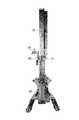
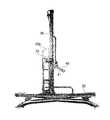
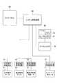
図1ないし図3は、本発明の実施例1に係る自動多角度撮影システムの要部斜視図,要部正面図,および要部側面図である。図4は、本実施例1に係る自動多角度撮影システムの動作説明図である。図5は、本実施例1に係る自動多角度撮影システムの回路ブロック図である。 1 to 3 are a perspective view, a front view, and a side view of main parts of an automatic multi-angle photographing system according to
本実施例1に係る自動多角度撮影システムは、図1ないし図4に示すように、ターンテーブル10と、水平軸スライダ装置20と、垂直軸スライダ装置30と、エクステンションアーム40と、デジタルカメラ70とから、その主要部が構成されている。水平軸スライダ装置20,垂直軸スライダ装置30およびエクステンションアーム40は、2軸直交スライド関節および1軸曲げ関節を備える多関節ロボットを構成しており、以下、これらを適宜「ロボット」と呼ぶことがある。なお、図4中、符号90は撮影対象である被写体(ワーク)を示す。被写体90は、一般的には商品であるが、人物等の他の物である場合もある。 As shown in FIGS. 1 to 4, the automatic multi-angle photographing system according to the first embodiment includes a
ターンテーブル10は、図4に示すように、被写体90を載置し、ターンテーブル用モータ11によって回転駆動される回転台である。ターンテーブル用モータ11は、図5に示すように、ターンテーブル用制御装置12を介してシステム制御装置50に接続されている。 As shown in FIG. 4, the
水平軸スライダ装置20は、図6(a),(b),(c)に示すように、水平軸用モータ21(図5参照)を内蔵する水平軸スライダ本体23と、水平軸スライダ本体23の左右両側面に水平方向に摺動自在に配設された左右の水平軸スライダ24a,24bと、水平軸スライダ本体23の上面に配設されたスクリューカバー25と、水平軸スライダ本体23の一端に設けられたモータハウジング26と、モータハウジング26から引き出されたケーブル27とを含んで構成されている。水平軸用モータ21は、図5に示すように、水平軸用制御装置22を介してシステム制御装置50に接続されている。 As shown in FIGS. 6A, 6B, and 6C, the horizontal
なお、垂直軸スライダ装置30は、図6(a),(b),(c)に示した水平軸スライダ装置20と同様に構成されているので、詳しい説明を割愛する。以下、垂直軸スライダ装置30の、水平軸スライダ装置20との対応部分は、水平軸スライダ装置20の対応部分の符号に10を加算した符号で示す。垂直軸スライダ装置30は、図4に示すように、水平軸スライダ装置20の水平軸スライダ24a,24bに起立するように取り付けられており、補強部材30aによって倒れないように補強されている。垂直軸用モータ31は、図5に示すように、垂直軸用制御装置32を介してシステム制御装置50に接続されている。 The vertical
エクステンションアーム40は、撮影角度軸用モータ41(本発明の撮影角度軸用ロータリアクチュエータに相当)の出力軸45(図7(a)参照)に揺動可能に取り付けられている。撮影角度軸用モータ41は、図5に示すように、撮影角度軸用制御装置42を介してシステム制御装置50に接続されている。撮影角度軸用モータ41は、図7(a),(b),(c)に示すように、撮影角度軸用モータ本体43と、撮影角度軸用モータ本体43の前面に突出するように設けられたフランジ44と、フランジ44に突出するように設けられた出力軸45とを含んで構成されている。デジタルカメラ70を撮影角度軸用モータ41の出力軸45に直接取り付けると、デジタルカメラ70を高い位置(以下、撮影高さという)まで移動させる場合に、垂直軸スライダ装置30が高くなって高価になり、かつ移動が困難になる。これに対して、図8に示すように、デジタルカメラ70をエクステンションアーム40を介して撮影角度軸用モータ41の出力軸45に取り付けると、垂直軸スライダ装置30を高くすることなしに、デジタルカメラ70の撮影高さを高くすることが可能になるとともに、場合によっては撮影角度θを90°にして被写体90を真上からオーバーハング撮影することが可能になる。例えば、垂直軸スライダ装置30の撮影高さが170cmのときに、エクステンションアーム40の長さを50cmとすると、エクステンションアーム40の角度が60°のときに、デジタルカメラ70の高さを200cmまでに伸ばすことができる。すなわち、エクステンションアーム40にデジタルカメラ70を取り付けたときの可能範囲は、撮影角度軸用モータ41にデジタルカメラ70を取り付けたときの可能範囲よりも広くなる。 The
図5は、本実施例1に係る自動多角度撮影システムの回路ブロック図である。本実施例1に係る自動多角度撮影システムは、ターンテーブル10を回転させるターンテーブル用モータ11と、ターンテーブル用モータ11に接続されたターンテーブル用制御装置12と、水平軸スライダ装置20に内蔵された水平軸用モータ21と、水平軸用モータ21に接続された水平軸用制御装置22と、垂直軸スライダ装置30に内蔵された垂直軸用モータ31と、垂直軸用モータ31に接続された垂直軸用制御装置32と、エクステンションアーム40を取り付けた撮影角度軸用モータ41と、撮影角度軸用モータ41に接続された撮影角度軸用制御装置42と、ターンテーブル用制御装置12,水平軸用制御装置22,垂直軸用制御装置32および撮影角度軸用制御装置42に接続されたシステム制御装置50と、システム制御装置50に接続されたタッチパネル60と、システム制御装置50に接続されたデジタルカメラ70と、デジタルカメラ70に接続されたパーソナルコンピュータ(以下、パソコンと略記する)80とから、その主要部が構成されている。 FIG. 5 is a circuit block diagram of the automatic multi-angle imaging system according to the first embodiment. The automatic multi-angle imaging system according to the first embodiment is built in a
システム制御装置50は、自動多角度撮影システム全体を制御するシーケンサユニットである。具体的には、システム制御装置50は、計算したデジタルカメラ70の撮影位置に基づいて、水平軸用モータ21,垂直軸用モータ31,撮影角度軸用モータ41およびターンテーブル用モータ11の駆動制御情報をターンテーブル用制御装置12,水平軸用制御装置22,垂直軸用制御装置32および撮影角度軸用制御装置42にそれぞれ出力する。ターンテーブル用制御装置12,水平軸用制御装置22,垂直軸用制御装置32および撮影角度軸用制御装置42は、駆動制御情報に基づいて水平軸用モータ21,垂直軸用モータ31,撮影角度軸用モータ41およびターンテーブル用モータ11を駆動制御する。 The
タッチパネル60は、例えば、小型のカラー液晶表示装置であり、画面に指を触れることによって入力操作可能となっている。なお、タッチパネル60に表示される各画面については、図11ないし図22を用いて後述する。 The
デジタルカメラ70は、一般的なデジタルスチールカメラであるが、スチール撮影機能を有するデジタルビデオカメラ等であってもよいことはいうまでもない。 The
パソコン80は、詳しい説明は省略するが、デジタルカメラ70との接続時に自動的に立ち上がるデジタルカメラ用ユーティリティプログラム(以下、単にユーティリティと略記する)81がインストール(搭載)されている。ユーティリティ81は、デジタルカメラ70からライブビューを動的に入力してパソコン80のディスプレイに表示するようになっており、デジタルカメラ70の撮影高さや撮影画角等を調整するために使用される。また、ユーティリティ81は、デジタルカメラ70のカメラ制御用接点(具体的には、カメラシャッタ)がONされると、デジタルカメラ70から撮影画像を自動的に取り込んで、パソコン80のメモリ82に逐次記憶するようになっている。 Although not described in detail, the
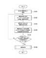
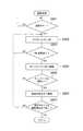
図9を参照すると、システム制御装置50の基本処理は、前回撮影原点移動工程S101と、撮影条件設定工程S102と、撮影原点変更工程S103と、水平座標・垂直座標計算処理工程S104と、可動範囲内判定工程S105と、撮影処理工程S106とからなる。 Referring to FIG. 9, the basic processing of the
図9中の撮影処理工程S106は、さらに図10に示すように、撮影スタート判定工程S201と、カメラシャッターON工程S202と、1枚撮影終了判定工程S203と、ターンテーブル次移動工程S204と、ターンテーブル1周終了判定工程S205と、撮影角度次移動工程S206と、撮影角度終了判定工程S207とからなる。 Further, as shown in FIG. 10, the photographing processing step S106 in FIG. 9 includes a photographing start determining step S201, a camera shutter ON step S202, a single photographing end determining step S203, a turntable next moving step S204, It consists of a table one-round end determination step S205, a shooting angle next movement step S206, and a shooting angle end determination step S207.
次に、このように構成された本実施例1の自動多角度撮影システムの動作について説明する。 Next, the operation of the automatic multi-angle photographing system of the first embodiment configured as described above will be described.
自動多角度撮影システムの起動時にタッチパネル60に表示される起動画面には、図11に示すように、ロボット無しボタン111,メカ原点移動中ランプ112,ロボット有りボタン113,入力可モニタランプ114,およびメニューボタン115が設けられている。電源が立ち上がると、ロボット無しボタン111が選択された状態で立ち上がる。ロボット有りボタン113に指が触れると、システム制御装置50は、水平軸スライダ装置20,垂直軸スライダ装置30およびエクステンションアーム40を水平軸(X軸),垂直軸(Y軸),撮影角度軸(θ軸)のメカ原点に動かす。メカ原点移動中は、各軸メカ原点移動中ランプ112が点滅表示する。メカ原点移動が終了すると、システム制御装置50は、水平軸スライダ装置20,垂直軸スライダ装置30およびエクステンションアーム40を、前回設定した原点に自動的に移動する。各軸の移動動作が完了すると、システム制御装置50は、タッチパネル60の起動画面に表示されたメニュー入力可ランプ114を点灯し、メニューボタン115の入力待ちになる。 As shown in FIG. 11, the startup screen displayed on the
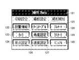
タッチパネル60に表示された起動画面においてメニューボタン115に指が触れると、システム制御装置50は、タッチパネル60に、図12に示すような操作メニュー画面を表示させる。操作メニュー画面には、ターンテーブル10の回転位置およびエクステンションアーム40の撮影角度θのデータ登録のための設置情報ボタン122と、カメラ制御用接点ON時間,OFF時間および回数の設定のためのカメラボタン123と、撮影時の原点(デジタルカメラ70の撮影角度θ,水平座標X,垂直座標Y)の設定のための原点設定ボタン124と、ターンテーブル10の水平分割数,ストロボ有無,オート撮影の時の次ステップ移動のインターバル時間の設定をするターンテーブルボタン125と、撮影時のデジタルカメラ70の撮影角度θを設定する角度設定ボタン126と、ターンテーブル10およびデジタルカメラ70の水平,垂直,回転速度の設定のための速度設定ボタン127と、被写体90を自動で写真撮影するときに使用するフルオートボタン128と、被写体90を1枚写真撮影する毎に確認しながら写真撮影するときに使用するセミオートボタン129と、被写体90の画角やデジタルカメラ70の位置を確認するときに使用するマニュアルボタン130とが設けられている。なお、起動画面ボタン(操作メニューアイコン)121に指を触れると、システム制御装置50は、タッチパネル60の表示を起動画面(図11参照)に切り替える。 When a finger touches the
タッチパネル60に表示された操作メニュー画面(図12参照)において設置情報ボタン122に指が触れると、システム制御装置50は、タッチパネル60に、図13に示すような設置情報画面(メカ設定画面)を表示する。設置情報画面(メカ設定画面)には、水平軸メカ原点ターンテーブル距離フィールド131と、ターンテーブル微調整ボタン132と、エクステンションアーム長さフィールド133と、デジタルカメラ振り角度フィールド134とが設けられている。水平軸メカ原点ターンテーブル距離フィールド131には、ロボットのメカ原点(水平軸のメカ原点)からターンテーブル10の中心までの撮影距離Lcamを水平軸メカ原点ターンテーブル距離フィールド131に設定する。水平軸メカ原点ターンテーブル距離フィールド131の場所をタッチし直接数値で入力する。ターンテーブル微調整ボタン132は、ターンテーブル10の位置情報の微調整に使用する。ターンテーブル微調整ボタン132で微調整したときは、リアルタイムでデジタルカメラ70の位置情報が更新される。エクステンションアーム長さフィールド133には、撮影角度軸用モータ41の出力軸45からデジタルカメラ70までのエクステンションアーム40の長さLextを設定する。デジタルカメラ振り角度フィールド134には、デジタルカメラ70のレンズ光軸を水平にしたときのデジタルカメラ70を中心にしてエクステンションアーム40の水平からの時計回りの振り角度αを設定する。When a finger touches the
タッチパネル60に表示された操作メニュー画面(図12参照)においてカメラボタン123に指が触れると、システム制御装置50は、タッチパネル60に、図14に示すようなカメラ設定画面を表示する。カメラ設定画面には、デジタルカメラ70のカメラ制御用接点ON時間を設定するシャッタON時間フィールド141と、カメラ制御用接点OFF時間を設定するシャッタOFF時間フィールド142と、カメラ制御ON−OFF繰返回数を設定するシャッタ実行回数フィールド143とが設けられている。シャッタON時間フィールド141には、カメラ制御用接点ON時間を数値で入力する。シャッタOFF時間フィールド142には、カメラ制御用接点OFF時間を数値で入力する。シャッタ実行回数フィールド143には、カメラ制御用接点ON−OFFの繰り返し回数を数値で入力する。 When a finger touches the camera button 123 on the operation menu screen (see FIG. 12) displayed on the
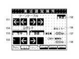
タッチパネル60に表示された操作メニュー画面(図12参照)において原点設定ボタン124に指が触れると、システム制御装置50は、タッチパネル60に、図15に示すような原点設定操作画面を表示する。原点設定操作画面には、ターンテーブル原点調整ボタン151と、角度選択ボタン152と、水平選択ボタン153と、垂直選択ボタン154と、角度・水平・垂直調整ボタン155と、設定エラー表示ランプ156と、補正値フィールド157と、カメラ被写体距離フィールド158とが設けられている。ターンテーブル10の原点の設定は、ターンテーブル原点調整ボタン151の外側の「←」または「→」ボタンを押すと、高速で回転する。速度は、速度設定で登録されている速度である。ターンテーブル原点調整ボタン151の内側の「←」または「→」ボタンを押すと、低速で回転する。微調整で使用し、低速の速度は固定である。角度・水平・垂直原点の設定は、角度選択ボタン152,水平選択ボタン153,および垂直選択ボタン154に指を触れることにより、撮影角度θ,水平距離Xおよび垂直距離Yを設定できる。撮影角度θは、角度選択ボタン152でデジタルカメラ70を選択し、角度・水平・垂直調整ボタン155で調整する。補正値が補正値フィールド157に表示される。デジタルカメラ70を交換して水平がずれたときに使用する。水平は、水平選択ボタン153で水平を選択し、角度・水平・垂直調整ボタン155でデジタルカメラ70の水平位置を調整する。補正値が補正値フィールド157に表示される。デジタルカメラ70からターンテーブル10の撮影中心までの撮影距離Lcamがカメラ被写体距離フィールド158に表示される。被写体90の大きさに応じてデジタルカメラ70から被写体90までの距離を変えたいときに使用する。選択されている撮影角度θでの撮影可能範囲を超えたときは、設定エラー表示ランプ156に設定エラーの文字が点滅表示する。垂直選択ボタン154で垂直を選択し、角度・水平・垂直調整ボタン155でデジタルカメラ70の垂直位置を調整する。補正値が補正値フィールド157に表示される。被写体90の高さにより撮影の中心原点を変更したいときに使用する。選択されている撮影角度θでの撮影可能範囲を超えたときは、設定エラー表示ランプ156に設定エラーの文字が点滅表示する。設定エラーが表示されたときは、水平位置の変更等で設定エラーにならないように調整する。When a finger touches the
タッチパネル60に表示された操作メニュー画面(図12参照)においてターンテーブルボタン125に指が触れると、システム制御装置50は、タッチパネル60に、図16に示すようなターンテーブル位置登録画面を表示する。ターンテーブル位置登録画面には、撮影位置指定フィールド161と、ストロボ有りボタン162と、ストロボ無しボタン163と、ストロボ有無両方ボタン164と、次位置移動インターバル時間フィールド165とが設けられている。撮影位置指定フィールド161には、ターンテーブル10の1周の分割数(水平分割数)を数値で設定する。ただし、割り切れない分割数(例7,11,13,17等)は設定できない。設定すると、ターンテーブル分割数設定エラーになる。ストロボ有りボタン162,ストロボ無しボタン163またはストロボ有無両方ボタン164にて、オートモード撮影時ストロボ有り,無しまたは両方を選択する。両方を選択した場合は、撮影枚数はストロボ有り、無しの2倍の枚数になる。次位置移動インターバル時間フィールド165には、オートモード撮影時の次位置移動までのインターバル時間を数値で指定する。デジタル画像転送時間によって画像データ転送が間に合うように設定する。 When the finger touches the
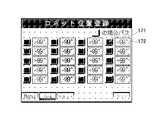
タッチパネル60に表示された操作メニュー画面(図12参照)において角度設定ボタン126に指が触れると、システム制御装置50は、タッチパネル60に、図17に示すようなロボット位置登録画面を表示する。ロボット位置登録画面には、選択ボタン171および撮影角度フィールド172の組が、複数ポジション(図では20ポジション)分設けられている。デジタルカメラ70の撮影角度θの設定は、撮影するデジタルカメラ70のレンズ光軸の角度を設定する。最大20ポジションまで設定できる。電源投入時は、初期値として0°,30°および60°が選択される。選択ボタン171で選択/非選択を設定できる。撮影角度フィールド172には、撮影角度θを数値で入力する。ただし、撮影角度0°は変更できない。 When the finger touches the
タッチパネル60に表示された操作メニュー画面(図12参照)において速度設定ボタン127に指が触れると、システム制御装置50は、タッチパネル60に、図18に示すような動作速度設定画面を表示する。動作速度設定画面には、ターンテーブル回転速度フィールド181と、水平軸移動速度(ロボットX)フィールド182と、垂直軸移動速度(ロボットY)フィールド183と、カメラ回転軸速度(ロボットθ)フィールド184とが設けられている。ターンテーブル回転速度フィールド181には、ターンテーブル10の回転速度を数値で設定する。水平軸移動速度フィールド182には、水平方向移動速度を数値で設定する。垂直軸移動速度フィールド183には、垂直方向移動速度を数値で設定する。カメラ回転軸速度フィールド184には、デジタルカメラ70(エクステンションアーム40)の回転速度を数値で設定する。 When the finger touches the
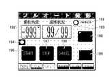
タッチパネル60に表示された操作メニュー画面(図12参照)においてフルオートボタン128に指が触れると、システム制御装置50は、タッチパネル60に、図19に示すようなフルオート撮影画面を表示する。フルオート撮影画面には、一時停止中のときに点滅表示する一時停止中ランプ191と、現在撮影中の撮影角度θを表示する撮影角度フィールド192と、現在撮影中のステップ数/ターンテーブル分割数(水平分割数)を入力する撮影ステップ/水平分割数フィールド193と、ロボット動作中(ボタン入力不可)を赤で示し、ボタン入力可を緑で示す動作中モニタランプ194と、カメラ制御用接点をONするカメラ制御ONボタン195と、オート撮影スタートボタン196と、オート撮影一時停止ボタン197と、オート被写体撮影を中止して原点に移動させるオート撮影中止ボタン198と、水平撮影毎一時停止ボタン199とが設けられている。 When the finger touches the
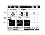
タッチパネル60に表示された操作メニュー画面(図12参照)においてセミオートボタン129に指が触れると、システム制御装置50は、タッチパネル60に、図20に示すようなセミオート撮影画面を表示する。セミオート撮影画面には、現在撮影中の撮影角度θを表示する撮影角度フィールド201と、現在撮影中のステップ数/ターンテーブル分割数(水平分割数)を表示する撮影ステップ/水平分割数フィールド202と、ロボット動作中(ボタン入力不可)を赤で示し、ボタン入力可を緑で示す動作中モニタランプ203と、撮影動作後に次ステップに移動するセミオート撮影ボタン204と、前ステップに移動(撮影無し)する1ステップ戻りボタン205と、撮影中止・原点移動をするセミオート撮影中止ボタン206とが設けられている。 When a finger touches the semi-auto button 129 on the operation menu screen (see FIG. 12) displayed on the
タッチパネル60に表示された操作メニュー画面(図12参照)においてマニュアルボタン130に指が触れると、システム制御装置50は、タッチパネル60に、図21に示すようなマニュアル撮影画面を表示する。マニュアル撮影画面には、撮影角度フィールド211と、撮影ステップ/水平分割数フィールド212と、ターンテーブル原点微調整ボタン213と、動作中モニタランプ214と、原点移動ボタン215と、ストロボON/OFFボタン216と、カメラ制御用接点ONボタン217と、撮影角度ステップアップボタン218と、撮影角度ステップダウンボタン219と、ターンテーブル左ボタン220と、ターンテーブル右ボタン221とが設けられている。 When a finger touches the
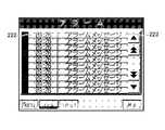
図13に示すメカ設定画面,図14に示すカメラ設定画面,図15に示す原点設定操作画面,図16に示すターンテーブル位置登録画面,図17に示すロボット位置登録画面,図18に示す動作速度設定画面,図19に示すフルオート撮影画面,図20に示すセミオート撮影画面,および図21に示すマニュアル撮影画面において点灯したアラームアイコンに指が触れると、システム制御装置50は、タッチパネル60に、図22に示すようなアラーム画面を表示する。アラーム画面には、アラーム発生時刻フィールド222とアラーム発生内容フィールド223との組が1つ以上設けられている。自動多角度撮影システムにエラーが発生すると、自動的にアラーム画面に切り替わる。アラーム発生時刻フィールド222にアラームの発生した時刻、アラーム発生内容フィールド223にアラーム内容が表示される。アラーム表示は、一度発生するとリセットアイコンで解除するまで保持される。アラームが発生すると、アラームアイコンが点滅する。一時的なアラームで問題が解決されている場合は、リセットアイコンにて解除する。戻るアイコンを押すと、前の画面に戻る。エラー状態が続いている場合は、リセットアイコンを押してもアラームは解除されない。 13, the camera setting screen shown in FIG. 14, the origin setting operation screen shown in FIG. 15, the turntable position registration screen shown in FIG. 16, the robot position registration screen shown in FIG. 17, and the operation speed shown in FIG. 18. When the finger touches the alarm icon that is lit on the setting screen, the fully automatic shooting screen shown in FIG. 19, the semi-automatic shooting screen shown in FIG. 20, and the manual shooting screen shown in FIG. An alarm screen as shown in FIG. 22 is displayed. The alarm screen is provided with at least one set of an alarm
撮影者は、デジタルカメラ70を通じて時々刻々と取り込まれパソコン80のディスプレイに表示されるライブビューを見ながら、デジタルカメラ70のレンズ光軸の初期高さを被写体90に合わせたり、撮影中心の高さや画角(視野角)を調整したりする。 The photographer adjusts the initial height of the optical axis of the lens of the
撮影者がオート撮影スタートボタン196に指を触れると、システム制御装置50は、デジタルカメラ70を前回の撮影原点に移動し(工程S101)、撮影条件を設定する(工程S102)。詳しくは、システム制御装置50は、ターンテーブル10の1周の分割数(水平分割数),撮影角度θ等を設定する。ここでは、水平分割数を12、撮影角度θを0°,30°および60°とし、全36ステップ(撮影位置)で被写体90の36枚の撮影画像群を自動的に撮影するフルオート撮影が設定されたものとする。 When the photographer touches the auto
次に、システム制御装置50は、被写体90に合わせて撮影原点を変更する(工程S103)。 Next, the
続いて、システム制御装置50は、撮影原点から現在設定されている撮影角度θの水平座標Xおよび垂直座標Yの計算処理を行う(工程S104)。詳しくは、被写体90の撮影中心からデジタルカメラ70までの撮影距離をLcam、被写体90から撮影角度軸用モータ41までの水平距離をL、撮影角度軸用モータ41からエクステンションアーム40に取り付けてあるデジタルカメラ70までの長さをLext、デジタルカメラ70のレンズ光軸を水平にしたときのエクステンションアーム40の振り角度をα、デジタルカメラ70のレンズ光軸を水平から撮影角度θのときのデジタルカメラ70のレンズ光軸を水平にしたところからの水平軸(X軸)の移動距離をΔX、垂直軸(Y軸)の移動距離をΔYとすると、以下のようになる。Subsequently, the
ΔX=L−(Lcam*cosθ−Lext*cos(α+θ),
ΔY=Lcam*sinθ−Lext*sin(α+θ)+Lext*sinα,
Lcam=(L+Lext*cosα)ΔX = L− (Lcam * cos θ−Lext * cos (α + θ),
ΔY = Lcam * sin θ−Lext * sin (α + θ) + Lext * sin α,
Lcam = (L + Lext * cos α)
水平軸方向移動距離ΔXおよび垂直軸方向移動距離ΔYが初期位置からの水平軸スライダ装置20および垂直軸スライダ装置30の移動距離になる。例えば、被写体−撮影角度軸水平距離Lが1700mm、エクステンションアーム長さLextが300mm、エクステンションアーム振り角度αが30°のときに、撮影角度θが0°であれば、被写体−カメラ水平距離Lcamは1959.808mmである。この条件で、撮影角度θが30°のときの水平軸方向移動距離ΔXおよび垂直軸方向移動距離ΔYは、152.8mmおよび870.1mmになる。また、撮影角度θが60°のときの水平軸方向移動距離ΔXおよび垂直軸方向移動距離ΔYは、720.1mmおよび1547.2mmになる。The horizontal axis direction movement distance ΔX and the vertical axis direction movement distance ΔY are the movement distances of the horizontal
次に、システム制御装置50は、計算された水平座標Xおよび垂直座標Yが可動範囲内に入っているかどうかを判定する(工程S105)。詳しくは、計算された水平座標Xおよび垂直座標Yが可動範囲内に入っていなければ、システム制御装置50は、工程S102に制御を戻して工程S102〜S105を繰り返す。計算された水平座標Xおよび垂直座標Yが可動範囲内に入っていれば、システム制御装置50は、撮影処理を行う(工程S106)。 Next, the
撮影処理工程S106では、システム制御装置50は、フルオート撮影がスタートしたかどうかを判定し(工程S201)、スタートしていなければ、工程S201を繰り返すことにより待機する。 In the photographing processing step S106, the
フルオート撮影がスタートしたと判断すると(工程S201でYES)、システム制御装置50は、デジタルカメラ70のカメラ制御用接点をONとし(工程S202)、1枚の写真撮影が終了したかどうかを判定する(工程S203)。1枚の写真撮影が終了していなければ(工程S202)、工程S202に制御を戻して、工程S202およびS203を繰り返す。 If it is determined that full-auto shooting has started (YES in step S201), the
1枚の写真撮影が終了していれば、システム制御装置50は、ターンテーブル10を次の回転角度φに移動し(工程S204)、ターンテーブル10が1周したかどうかを判定する(工程S205)。具体的には、水平分割数が12の場合、現在の回転角度φに30°を加えた次の回転角度に移動する。ターンテーブル10が1周していなければ、すなわち回転角度φが360°未満であれば、工程S202に制御を戻して、工程S202〜S205を繰り返す。 If one photo has been taken, the
ターンテーブル10が1周していれば、すなわち回転角度φが360°以上であれば、システム制御装置50は、撮影角度θを次の撮影角度θに移動する(工程S206)。例えば、被写体−撮影角度軸水平距離Lが1700mm、エクステンションアーム長さLextが300mm、エクステンションアーム振り角度αが30°の条件で、撮影角度θが0°から30°に移動するときに、水平軸スライダ装置20は水平軸方向移動距離ΔX=152.8mmに、垂直軸スライダ装置30は垂直軸方向移動距離ΔY=870.1mmに移動する。また、撮影角度θが30°から60°に移動するときに、水平軸スライダ装置20は水平軸方向移動距離ΔX=720.1mmに、垂直軸スライダ装置30は垂直軸方向移動距離ΔY=1547.2mmに移動する。次に、システム制御装置50は、設定されている撮影角度θの全てを終了したかどうかを判定する(工程S207)。具体的には、撮影角度θが0°,30°および60°に設定されている場合、撮影角度θが0°,30°および60°の全てが終了したかどうかを判定する。設定されている撮影角度θの全てを終了していなければ、システム制御装置50は、工程S202に制御を戻して、工程S202〜S207を繰り返す。If the
設定されている撮影角度θの全てを終了していれば、システム制御装置50は、撮影処理工程S106からリターンして基本処理に戻り、処理を終了する。 If all of the set shooting angles θ have been completed, the
本実施例1に係る自動多角度撮影システムによれば、デジタルカメラ70を垂直軸スライダ装置30に直接取り付けると、高い位置まで移動させる場合に、装置が大きくなって高価になり、かつ移動が困難になる。一方、エクステンションアーム40を介して垂直軸スライダ装置30を取り付けると、図8中に破線で示すように、装置を大きくすることなしに、撮影高さを高くすることが可能になるとともに、場合によっては撮影角度θを90°にして真上からオーバーハング撮影をすることが可能になる。例えば、垂直軸スライダ装置30の高さ170cmのときに、撮影角度θが60°のときに撮影高さ200cmまでの高さにできる。 According to the automatic multi-angle photographing system according to the first embodiment, when the
また、本実施例1に係る自動多角度撮影システムによれば、エクステンションアーム40の長さや、エクステンションアーム40へのデジタルカメラ70の取付位置を切り替えることにより、所望の撮影距離Xおよび所望の撮影角度θを容易に実現することができる。 Further, according to the automatic multi-angle photographing system according to the first embodiment, the desired photographing distance X and the desired photographing angle are changed by switching the length of the
以上、本発明の実施例1を説明したが、これはあくまでも例示にすぎず、本発明はこれに限定されるものではなく、特許請求の範囲の趣旨を逸脱しない限りにおいて、当業者の知識に基づく種々の変更が可能である。 As described above, the first embodiment of the present invention has been described. However, this is merely an example, and the present invention is not limited to this, and the knowledge of those skilled in the art can be obtained without departing from the scope of the claims. Various modifications based on this are possible.
例えば、実施例1に係る自動多角度撮影システムによれば、デジタルカメラ70にパソコン80を接続して撮影位置(ステップ)毎にデジタルカメラ70により撮影された被写体90の撮影画像をパソコン80に自動的に取り込むようにしたが、デジタルカメラ70に撮影画像群を記憶する十分な記憶容量があるのであれば、パソコン80を接続しなくてもよい。 For example, according to the automatic multi-angle photographing system according to the first embodiment, the
また、実施例1に係る自動多角度撮影システムによれば、システム制御装置50によりターンテーブル10を回転制御するようにしたが、ターンテーブル10は別の制御系を通じて回転制御するようにしてもよい。極端に言えば、デジタルカメラ70による撮影毎に撮影者がターンテーブル10を一定の回転角度ずつ手動で回転させるようにすることもできる。 Further, according to the automatic multi-angle photographing system according to the first embodiment, the
本発明は、インターネットのWebサイト上でのバーチャルショップの商品表示ばかりでなく、デザイン,機械設計,人物全体像等の擬似立体画像での表示に広く利用することができる。 The present invention can be widely used not only for displaying products in a virtual shop on an Internet Web site, but also for displaying pseudo-stereoscopic images such as designs, machine designs, and human figures.
10 ターンテーブル
11 ターンテーブル用モータ
12 ターンテーブル用制御装置
20 水平軸スライダ装置
21 水平軸用モータ
22 水平軸用制御装置
24a,24b 水平軸スライダ
30 垂直軸スライダ装置
31 垂直軸用モータ
32 垂直軸用制御装置
34a,34b 垂直軸スライダ
40 エクステンションアーム
41 撮影角度軸用モータ(撮影角度軸用ロータリアクチュエータ)
42 撮影角度軸用制御装置
50 システム制御装置
60 タッチパネル
70 デジタルカメラ
80 パソコン(パーソナルコンピュータ)
90 被写体DESCRIPTION OF
42 Shooting Angle
90 subjects
Claims (5)
Translated fromJapanese前記水平軸スライダに取り付けられ、垂直方向に移動する垂直軸スライダを備える垂直軸スライダ装置と、
前記垂直軸スライダに固定された撮影角度軸用ロータリアクチュエータに揺動自在に取り付けられたエクステンションアームと、
前記エクステンションアームに取り付けられたデジタルカメラと、
自動多角度撮影に連動して、前記水平軸スライダ,前記垂直軸スライダおよび前記エクステンションアームの撮影位置を計算して、前記デジタルカメラのレンズ光軸が所望の撮影距離の円弧上の所望の撮影角度となるように、前記水平軸スライダ,前記垂直軸スライダおよび前記撮影角度軸用ロータリアクチュエータを駆動制御するとともに、撮影位置毎に前記デジタルカメラに被写体を撮影させるシステム制御装置と
を備えることを特徴とする自動多角度撮影システム。A horizontal axis slider device comprising a horizontal axis slider that moves in a horizontal direction toward the imaging center of the subject placed on the turntable;
A vertical axis slider device comprising a vertical axis slider attached to the horizontal axis slider and moving in the vertical direction;
An extension arm swingably attached to a rotary actuator for a photographing angle axis fixed to the vertical axis slider;
A digital camera attached to the extension arm;
In conjunction with automatic multi-angle shooting, the shooting positions of the horizontal axis slider, the vertical axis slider and the extension arm are calculated so that the lens optical axis of the digital camera has a desired shooting angle on an arc of a desired shooting distance. And a system control device for driving and controlling the horizontal axis slider, the vertical axis slider, and the shooting angle axis rotary actuator, and causing the digital camera to shoot a subject for each shooting position. Automatic multi-angle shooting system.
前記ターンテーブルに載置された被写体の撮影中心に向けて水平方向に移動する水平軸スライダを備える水平軸スライダ装置と、
前記水平軸スライダに取り付けられ、垂直方向に移動する垂直軸スライダを備える垂直軸スライダ装置と、
前記垂直軸スライダに固定された撮影角度軸用ロータリアクチュエータに揺動自在に取り付けられたエクステンションアームと、
前記エクステンションアームに取り付けられたデジタルカメラと、
自動多角度撮影に連動して、前記ターンテーブル,前記水平軸スライダ,前記垂直軸スライダおよび前記エクステンションアームの撮影位置を計算して、前記ターンテーブルを所定の回転角度ずつ回転制御し、前記デジタルカメラのレンズ光軸が所望の撮影距離の円弧上の所望の撮影角度となるように、前記ターンテーブル,前記水平軸スライダ,前記垂直軸スライダおよび前記撮影角度軸用ロータリアクチュエータを駆動制御するとともに、撮影位置毎に前記デジタルカメラに被写体を撮影させるシステム制御装置と
を備えることを特徴とする自動多角度撮影システム。A turntable on which a subject is placed and rotated;
A horizontal axis slider device comprising a horizontal axis slider that moves in a horizontal direction toward the imaging center of the subject placed on the turntable;
A vertical axis slider device comprising a vertical axis slider attached to the horizontal axis slider and moving in the vertical direction;
An extension arm swingably attached to a rotary actuator for a photographing angle axis fixed to the vertical axis slider;
A digital camera attached to the extension arm;
In conjunction with automatic multi-angle shooting, the shooting positions of the turntable, the horizontal axis slider, the vertical axis slider, and the extension arm are calculated, and the turntable is rotated and controlled by a predetermined rotation angle. The turntable, the horizontal axis slider, the vertical axis slider, and the rotary actuator for the imaging angle axis are driven and controlled so that the lens optical axis of the lens has a desired imaging angle on the arc of a desired imaging distance. An automatic multi-angle photographing system comprising: a system control device that causes the digital camera to photograph a subject for each position.
ΔX=L−(Lcam*cosθ−Lext*cos(α+θ),
ΔY=Lcam*sinθ−Lext*sin(α+θ)+Lext*sinα,
Lcam=(L+Lext*cosα)
であり、前記水平軸方向移動距離ΔXおよび前記垂直軸方向移動距離ΔYが初期位置からの前記水平軸スライダの移動距離および前記垂直軸スライダの移動距離になることを特徴とする請求項1ないし4のいずれか1項に記載の自動多角度撮影システム。The system control device is provided with a shooting distance from the digital camera to the shooting center of the subject Lcam , a horizontal distance from the subject to the shooting angle axis rotary actuator, and the shooting angle axis rotary actuator attached. The length of the extension arm is Lext , the angle of the extension arm when the lens optical axis of the digital camera is horizontal is α, and the angle of the digital camera when the lens optical axis of the digital camera is horizontal to the shooting angle θ If the horizontal axis direction moving distance from the horizontal position of the lens optical axis is ΔX and the vertical axis direction moving distance is ΔY,
ΔX = L− (Lcam * cos θ−Lext * cos (α + θ),
ΔY = Lcam * sin θ−Lext * sin (α + θ) + Lext * sin α,
Lcam = (L + Lext * cos α)
5. The horizontal axis direction movement distance ΔX and the vertical axis direction movement distance ΔY are the horizontal axis slider movement distance and the vertical axis slider movement distance from an initial position, respectively. The automatic multi-angle imaging system according to any one of the above.
Priority Applications (1)
| Application Number | Priority Date | Filing Date | Title |
|---|---|---|---|
| JP2009027043AJP4700739B2 (en) | 2009-02-09 | 2009-02-09 | Automatic multi-angle shooting system |
Applications Claiming Priority (1)
| Application Number | Priority Date | Filing Date | Title |
|---|---|---|---|
| JP2009027043AJP4700739B2 (en) | 2009-02-09 | 2009-02-09 | Automatic multi-angle shooting system |
Publications (2)
| Publication Number | Publication Date |
|---|---|
| JP2010183476A JP2010183476A (en) | 2010-08-19 |
| JP4700739B2true JP4700739B2 (en) | 2011-06-15 |
Family
ID=42764627
Family Applications (1)
| Application Number | Title | Priority Date | Filing Date |
|---|---|---|---|
| JP2009027043AExpired - Fee RelatedJP4700739B2 (en) | 2009-02-09 | 2009-02-09 | Automatic multi-angle shooting system |
Country Status (1)
| Country | Link |
|---|---|
| JP (1) | JP4700739B2 (en) |
Cited By (3)
| Publication number | Priority date | Publication date | Assignee | Title |
|---|---|---|---|---|
| US10122997B1 (en) | 2017-05-03 | 2018-11-06 | Lowe's Companies, Inc. | Automated matrix photo framing using range camera input |
| US12189915B2 (en) | 2022-06-24 | 2025-01-07 | Lowe's Companies, Inc. | Simulated environment for presenting virtual objects and virtual resets |
| US12211161B2 (en) | 2022-06-24 | 2025-01-28 | Lowe's Companies, Inc. | Reset modeling based on reset and object properties |
Families Citing this family (3)
| Publication number | Priority date | Publication date | Assignee | Title |
|---|---|---|---|---|
| JP5499802B2 (en)* | 2010-03-18 | 2014-05-21 | 株式会社デンソーウェーブ | Visual inspection system |
| CN113108185B (en)* | 2021-05-07 | 2025-05-23 | 浪尖设计集团有限公司 | Camera tripod head adjusting structure |
| JP7299544B1 (en) | 2022-09-02 | 2023-06-28 | キヤノンマーケティングジャパン株式会社 | Information processing system, information processing system control method and program |
Family Cites Families (4)
| Publication number | Priority date | Publication date | Assignee | Title |
|---|---|---|---|---|
| JP4288753B2 (en)* | 1999-05-31 | 2009-07-01 | コニカミノルタセンシング株式会社 | 3D data input device |
| JP2004248231A (en)* | 2002-12-19 | 2004-09-02 | Meta Corporation Japan | Image capturing system and image display system |
| JP2004274254A (en)* | 2003-03-06 | 2004-09-30 | Ricoh Co Ltd | Image input apparatus |
| JP2009211671A (en)* | 2008-02-08 | 2009-09-17 | Yuu System:Kk | Device and method for displaying merchandise in virtual shop |
- 2009
- 2009-02-09JPJP2009027043Apatent/JP4700739B2/ennot_activeExpired - Fee Related
Cited By (3)
| Publication number | Priority date | Publication date | Assignee | Title |
|---|---|---|---|---|
| US10122997B1 (en) | 2017-05-03 | 2018-11-06 | Lowe's Companies, Inc. | Automated matrix photo framing using range camera input |
| US12189915B2 (en) | 2022-06-24 | 2025-01-07 | Lowe's Companies, Inc. | Simulated environment for presenting virtual objects and virtual resets |
| US12211161B2 (en) | 2022-06-24 | 2025-01-28 | Lowe's Companies, Inc. | Reset modeling based on reset and object properties |
Also Published As
| Publication number | Publication date |
|---|---|
| JP2010183476A (en) | 2010-08-19 |
Similar Documents
| Publication | Publication Date | Title |
|---|---|---|
| JP4700739B2 (en) | Automatic multi-angle shooting system | |
| EP2405299B1 (en) | Information processing device, information processing method, and program | |
| TWI476505B (en) | Method and electric device for taking panoramic photograph | |
| JP5063749B2 (en) | Imaging control system, imaging apparatus control apparatus, control method therefor, and program | |
| US20160132962A1 (en) | Three-dimensional shopping platform displaying system | |
| US9485421B2 (en) | Method and apparatus for operating camera function in portable terminal | |
| CN107026973A (en) | Image processing apparatus, image processing method and photographic auxiliary equipment | |
| WO2012149983A1 (en) | Imaging apparatus and controller for photographing products | |
| US9544556B2 (en) | Projection control apparatus and projection control method | |
| JP2006244329A (en) | Mobile terminal, information processing apparatus and system | |
| JP2013009189A (en) | Imaging device and imaging method | |
| CN104320590A (en) | Split-screen image processing method and device and client terminal | |
| US20120162459A1 (en) | Image capturing apparatus and image patchwork method thereof | |
| TWI484285B (en) | Panorama photographing method | |
| WO2025036252A1 (en) | Photographing method, and terminal, electronic device and readable storage medium | |
| CN113287296A (en) | Control method, handheld cloud deck, system and computer readable storage medium | |
| JP6583745B2 (en) | Online shopping system | |
| JP2011101289A (en) | Image display device, and image display method | |
| Chu et al. | Design of a motion-based gestural menu-selection interface for a self-portrait camera | |
| CN112333395A (en) | Focus control method, device and electronic device | |
| CN113260942A (en) | Handheld holder control method, handheld holder, system and readable storage medium | |
| KR100787987B1 (en) | Control device of pan tilt camera and its recording medium | |
| JP2014062932A (en) | Attitude control device, operation device, attitude control system, control method, control program, and recording medium | |
| JP7021900B2 (en) | Image provision method | |
| CN114205532B (en) | Shooting method, device, equipment and medium of virtual camera |
Legal Events
| Date | Code | Title | Description |
|---|---|---|---|
| A977 | Report on retrieval | Free format text:JAPANESE INTERMEDIATE CODE: A971007 Effective date:20110131 | |
| A871 | Explanation of circumstances concerning accelerated examination | Free format text:JAPANESE INTERMEDIATE CODE: A871 Effective date:20110127 | |
| A01 | Written decision to grant a patent or to grant a registration (utility model) | Free format text:JAPANESE INTERMEDIATE CODE: A01 Effective date:20110221 | |
| A975 | Report on accelerated examination | Free format text:JAPANESE INTERMEDIATE CODE: A971005 Effective date:20110217 | |
| A61 | First payment of annual fees (during grant procedure) | Free format text:JAPANESE INTERMEDIATE CODE: A61 Effective date:20110304 | |
| R250 | Receipt of annual fees | Free format text:JAPANESE INTERMEDIATE CODE: R250 | |
| R250 | Receipt of annual fees | Free format text:JAPANESE INTERMEDIATE CODE: R250 | |
| LAPS | Cancellation because of no payment of annual fees |