JP4700585B2 - Motorcycle rear wheel suspension system - Google Patents
Motorcycle rear wheel suspension systemDownload PDFInfo
- Publication number
- JP4700585B2 JP4700585B2JP2006269378AJP2006269378AJP4700585B2JP 4700585 B2JP4700585 B2JP 4700585B2JP 2006269378 AJP2006269378 AJP 2006269378AJP 2006269378 AJP2006269378 AJP 2006269378AJP 4700585 B2JP4700585 B2JP 4700585B2
- Authority
- JP
- Japan
- Prior art keywords
- rear wheel
- arm member
- arm
- knuckle
- shaft
- Prior art date
- Legal status (The legal status is an assumption and is not a legal conclusion. Google has not performed a legal analysis and makes no representation as to the accuracy of the status listed.)
- Expired - Fee Related
Links
Images


Classifications
- B—PERFORMING OPERATIONS; TRANSPORTING
- B62—LAND VEHICLES FOR TRAVELLING OTHERWISE THAN ON RAILS
- B62K—CYCLES; CYCLE FRAMES; CYCLE STEERING DEVICES; RIDER-OPERATED TERMINAL CONTROLS SPECIALLY ADAPTED FOR CYCLES; CYCLE AXLE SUSPENSIONS; CYCLE SIDE-CARS, FORECARS, OR THE LIKE
- B62K25/00—Axle suspensions
- B62K25/04—Axle suspensions for mounting axles resiliently on cycle frame or fork
- B62K25/28—Axle suspensions for mounting axles resiliently on cycle frame or fork with pivoted chain-stay
- B62K25/283—Axle suspensions for mounting axles resiliently on cycle frame or fork with pivoted chain-stay for cycles without a pedal crank, e.g. motorcycles
- B—PERFORMING OPERATIONS; TRANSPORTING
- B62—LAND VEHICLES FOR TRAVELLING OTHERWISE THAN ON RAILS
- B62M—RIDER PROPULSION OF WHEELED VEHICLES OR SLEDGES; POWERED PROPULSION OF SLEDGES OR SINGLE-TRACK CYCLES; TRANSMISSIONS SPECIALLY ADAPTED FOR SUCH VEHICLES
- B62M17/00—Transmissions characterised by use of rotary shaft, e.g. cardan shaft
Landscapes
- Engineering & Computer Science (AREA)
- Mechanical Engineering (AREA)
- Chemical & Material Sciences (AREA)
- Combustion & Propulsion (AREA)
- Transportation (AREA)
- Axle Suspensions And Sidecars For Cycles (AREA)
- Vehicle Body Suspensions (AREA)
Description
Translated fromJapanese本発明は、後輪を軸支するナックル部材の上部に、車体フレームに前端部が軸支されて後方に延びる上アーム部材の後端部が回動可能に連結され、前記車体フレームに前端部が軸支されて前記上アーム部材の下方で後方に延びる下アーム部材の後端部が、前記ナックル部材の下部に回動可能に連結される自動二輪車の後輪懸架装置に関する。 According to the present invention, a rear end portion of an upper arm member that is pivotally supported by a vehicle body frame and extends rearward is pivotally connected to an upper portion of a knuckle member that pivotally supports a rear wheel, and the front end portion is connected to the vehicle body frame. The present invention relates to a rear wheel suspension device for a motorcycle in which a rear end portion of a lower arm member that is pivotally supported and extends rearward below the upper arm member is rotatably connected to a lower portion of the knuckle member.
このような後輪懸架装置は、たとえば特許文献1で知られている。
ところが上記特許文献1で開示された後輪懸架装置では、リヤクッションユニットの一端が車体フレームに取付けられ、リヤクッションユニットの他端が上アーム部材および下アーム部材の一方に取付けられており、リヤクッションユニットの一端の車体フレームへの連結部の剛性を大きく確保することが必要となり、またプログレッシブなクッション特性を得ようとする場合には、複数のリンク部材の組み合わせが別途必要となる。 However, in the rear wheel suspension device disclosed in Patent Document 1, one end of the rear cushion unit is attached to the vehicle body frame, and the other end of the rear cushion unit is attached to one of the upper arm member and the lower arm member. It is necessary to ensure a large rigidity of the connecting portion of the one end of the cushion unit to the vehicle body frame, and in order to obtain progressive cushion characteristics, a combination of a plurality of link members is separately required.
本発明は、かかる事情に鑑みてなされたものであり、部品点数の増加を回避しつつプログレッシブなクッション特性を得ることを可能とするとともに、車体フレームでの余分な剛性確保を不要とした自動二輪車の後輪懸架装置を提供することを目的とする。 The present invention has been made in view of such circumstances, and allows a motorcycle to obtain a progressive cushion characteristic while avoiding an increase in the number of parts, and eliminates the need for securing extra rigidity in the body frame. An object of the present invention is to provide a rear wheel suspension device.
上記目的を達成するために、請求項1記載の発明は、後輪を軸支するナックル部材の上部に、車体フレームに前端部が軸支されて後方に延びる上アーム部材の後端部が回動可能に連結され、前記車体フレームに前端部が軸支されて前記上アーム部材の下方で後方に延びる下アーム部材の後端部が、前記ナックル部材の下部に回動可能に連結される自動二輪車の後輪懸架装置において、前記上アーム部材および前記下アーム部材のいずれか一方は、該一方のアーム部材の後端部が車両側面視で前記後輪のリムの径方向内方側まで延出し且つその後端部に前記ナックル部材が回動可能に連結されていて、後輪懸架のためのスイングアームを構成しており、前記上アーム部材および前記下アーム部材の他方のアーム部材の後端部は、前記ナックル部材の、少なくとも後輪外周近傍まで車体前方に延出させた腕部に回動可能に連結され、前記スイングアームを構成する前記一方のアーム部材にリヤクッションユニットの一端が連結されると共に、該リヤクッションユニットの他端が、前記他方のアーム部材および前記腕部の一方に連結されることを特徴とする。In order to achieve the above object, the invention according to claim 1 is characterized in that the rear end portion of the upper arm member that extends rearward is supported by the front end portion of the vehicle body frame and is supported on the upper portion of the knuckle member that supports the rear wheel. A rear end portion of a lower arm member that is movably connected and has a front end portion pivotally supported by the body frame and extending rearward below the upper arm member is rotatably connected to a lower portion of the knuckle member. In the rear wheel suspension device for a motorcycle, one of the upper arm member and the lower arm memberhas a rear end portion of the one arm member extending to a radially inward side of the rim of the rear wheel in a side view of the vehicle. out and the knuckle member to the rear end portion thereof have been pivotally connected to constitute a swing arm for the rear wheel suspension, the rear endof the otherarm member of the upper arm member and the lower arm memberpart, the knuckle partOf, pivotally connected to thearm portion which is extended toward the front of the vehicle body to the rear wheel near the outer circumference at leastone end of the rear cushion unit is connected to the arm member of the one constituting the swing arm, the rear The other end of the cushion unit is connected to one of the other arm member and thearm portion .
また請求項2記載の発明は、請求項1記載の発明の構成に加えて、前記他方のアーム部材および前記ナックル部材の連結部が、車両側面視で前記後輪の外周よりも外側方に配置されることを特徴とする。According to a second aspect of the present invention, in addition to the configuration of the first aspect of the invention, the connecting portion of the other arm member and the knuckle member is disposed outside the outer periphery of the rear wheel in a side view of thevehicle. It is characterized by being.
また請求項3記載の発明は、請求項1または請求項2記載の発明の構成に加えて、前記後輪は、後輪駆動シャフトによりエンジンの回転駆動力を伝達されると共に、前記後輪駆動シャフトは、車両側面視で前記スイングアームを構成する前記一方のアーム部材と、前記他方のアーム部材および前記腕部との間に配置されることを特徴とする。According to a third aspect of the present invention, in addition to the configuration of the first or second aspect of the present invention, the rear wheel is transmitted with the rotational driving force of the engine by a rear wheel drive shaft, and the rear wheel drive. The shaft is disposed between the one arm member constituting the swing arm, the other arm member, and the arm portion in a side view of the vehicle.
また請求項4記載の発明は、請求項3記載の発明の構成に加えて、前記後輪駆動シャフトは、それぞれ複数のシャフトと複数のユニバーサルジョイントとで構成され、一部のユニバーサルジョイントは、車両側面視で前記スイングアームを構成する前記一方のアーム部材と前記腕部との間に配置されることを特徴とする。According to a fourth aspect of the invention, in addition to the configuration of the third aspect of the invention, each of the rear wheel drive shafts includes a plurality of shafts and a plurality of universal joints. It is arranged between the one arm member constituting the swing arm and the arm portion in a side view.
また請求項5記載の発明は、請求項3または請求項4記載の発明の構成に加えて、前記後輪駆動シャフトの1つのシャフトにナイトハルト機構を備え、該ナイトハルト機構を備えるシャフトは、車両側面視で前記スイングアームを構成する前記一方のアーム部材と前記腕部との間に配置されることを特徴とする。According to a fifth aspect of the invention, in addition to the configuration of the third or fourth aspect of the invention, one shaft of the rear wheel drive shaft is provided with a Knighthard mechanism, and the shaft provided with the Knighthard mechanism is a vehicle side surface. It is arranged between the one arm member and the arm portion constituting the swing arm as viewed.
さらに請求項6記載の発明は、請求項1ないし請求項5のいずれかに記載の発明の構成に加えて、前記他方のアーム部材が前記下アーム部材であり、前上がりに傾斜した前記リヤクッションユニットの一端が前記上アーム部材に連結されることを特徴とする。Furthermore, in the invention according to claim6 , in addition to the configuration of the invention according toany one of claims 1 to 5 , the other arm member is the lower arm member, and the rear cushion is inclined upward. One end of the unit is connected to the upper arm member.
請求項1記載の発明によれば、リヤクッションユニットが、後輪懸架のためのスイングアームを構成する上アーム部材および下アーム部材の一方と、他方のアーム部材およびナックル部材の腕部の一方との間に設けられるものであるので、車体フレームの剛性確保を、上アーム部材および下アーム部材の前端部軸支部に集中することができ、車体フレームでの余分な剛性確保を不要とすることができ、しかもリンク部材等の部品を別途必要とすることなくプログレッシブなクッション特性を得ることを可能として部品点数の増加を回避することができる。According to the first aspect of the present invention, the rear cushion unit includes one ofan upper arm member and a lower arm memberconstituting a swing arm for suspension of therear wheel , and one of the other arm member and one ofthe arm portions of the knuckle member. Since the rigidity of the vehicle body frame can be concentrated on the front end shaft support portions of the upper arm member and the lower arm member, it is not necessary to ensure the extra rigidity in the vehicle body frame. In addition, it is possible to obtain a progressive cushion characteristic without requiring a separate component such as a link member, thereby avoiding an increase in the number of components.
また請求項2記載の発明によれば、ナックル部材を後輪の左右両側に配置される後輪支持部が一体に連結された構造とすることができ、車体フレームの幅方向中心位置にリヤクッションユニットを配置することが可能となる。 According to the invention described in claim 2, the knuckle member can be structured such that the rear wheel support portions disposed on the left and right sides of the rear wheel are integrally connected, and the rear cushion is located at the center position in the width direction of the vehicle body frame. Units can be placed.
また請求項3,4記載の発明によれば、後輪駆動シャフトの設計自由度を高めることができ、しかもユニバーサルジョイントを用いることで、後輪駆動シャフトを安価に構成することができるとともに、後輪駆動シャフトが嵩張らないようにすることができる。According to the third and fourth aspects of the invention, the design freedom of the rear wheel drive shaft can be increased, and the rear wheel drive shaft can be configured at low cost by using a universal joint, and the rear It is possible to prevent the wheel drive shaft from becoming bulky.
また請求項5記載の発明によれば、急加減速時等での後輪駆動シャフトのねじり方向の衝撃力を吸収するとともに、エンジンのトルク変動等によって生じるねじり振動を抑制することができる。According to the fifth aspect of the present invention, it is possible to absorb the impact force in the torsional direction of the rear wheel drive shaft at the time of rapid acceleration / deceleration and the like and to suppress the torsional vibration caused by the engine torque fluctuation.
さらに請求項6記載の発明によれば、走破性が良好であるプログレッシブなクッション特性の設定が可能となる。Furthermore, according to the invention described in claim6 , it is possible to set a progressive cushion characteristic with good running performance.
以下、本発明の実施の形態を、添付の図面に示した本発明の実施例に基づいて説明する。 DESCRIPTION OF THE PREFERRED EMBODIMENTS Embodiments of the present invention will be described below based on examples of the present invention shown in the accompanying drawings.
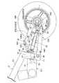
図1〜図5は本発明の第1実施例を示すものであり、図1は自動二輪車の側面図、図2は後輪駆動装置および後輪懸架装置の構成を示すための図1の要部拡大概略図、図3は図2の3矢視図、図4は後輪駆動装置の後部を示す切欠き側面図、図5は図4の5−5線断面図である。 1 to 5 show a first embodiment of the present invention, FIG. 1 is a side view of a motorcycle, and FIG. 2 is a diagram of FIG. 1 for showing the configuration of a rear wheel drive device and a rear wheel suspension device. 3 is an enlarged schematic view, FIG. 3 is a view taken in the direction of arrow 3 in FIG. 2, FIG. 4 is a cutaway side view showing the rear part of the rear wheel drive device, and FIG.
先ず図1において、自動二輪車の車体フレームFが前端に備えるヘッドパイプ11には、前輪WFを軸支するフロントフォーク12が操向可能に支承され、ヘッドパイプ11から後ろ下がりに延びる左右一対のメインフレーム13…の下方に配置されるエンジンユニットEUが車体フレームFに搭載される。 First, in FIG. 1, a
エンジンユニットEUは、クランクシャフト14を回転自在に支承するクランクケース15を有するエンジンEと、前記クランクシャフト14の回転動力を変速するようにして前記クランクケース15に内蔵される変速機Mとで構成されるものであり、前記クランクシャフト14と平行な回転軸線を有する出力軸16が前記クランクシャフト14の後方で前記クランクケース15に回転自在に支承される。 The engine unit EU includes an engine E having a crankcase 15 that rotatably supports the
前記メインフレーム13…の後部には上下に延びるピボットプレート17…が一体に連設されており、後輪WRは、後輪懸架装置18Aを介して前記ピボットプレート17…に連結される。また前記出力軸16の回転動力は、後輪WRを回転駆動する動力を伝達するようにして前後に延びる後輪駆動シャフト19の前端部にベベルギヤ機構20を介して伝達される。 A
図2および図3において、前記後輪懸架装置18Aは、車体フレームFにおけるピボットプレート17…に連結軸21を介して前端部が揺動可能に軸支されて後方に延びる上アーム部材22Aと、前記連結軸21よりも下方で前記ピボットプレート17…に連結軸23を介して前端部が揺動可能に軸支されるとともに上アーム部材22Aの下方で後方に延びる下アーム部材24Aと、後輪WRを軸支するとともに前記上アーム部材22Aおよび下アーム部材24Aの後端部がそれぞれ回動可能に連結されるナックル部材25Aと、リヤクッションユニット26とを備える。 2 and 3, the rear
前記上アーム部材22Aの後部は、後輪WRの前側上部を跨ぐように二股に分かれて形成される。また前記ナックル部材25Aは、前記後輪WRを軸支するようにして後輪WRの両側に配置される後輪支持部25Aa,25Abと、それらの後輪支持部25Aa,25Abの下部からそれぞれ前方に後輪WRの外周を越えて延びる腕部25Ac,25Adと、それらの腕部25Ac,25Adの前端部間を結ぶ連結部25Aeと、前記腕部25Ac,25Adよりも短く前記後輪支持部25Aa,25Abの上部から前方斜め上方に突出される上部腕部25Af…とを一体に有し、平面視で略U字状に形成される。而して前記上アーム部材22Aは、それの後端部が車両の側面視で後輪WRのリムrの径方向内方側まで延出し、前記後輪支持部25Aa,25Abの上部に連結軸42…を介して回動可能に連結されて後輪懸架のためのスイングアームを構成するものであり、この第1実施例では前記後輪支持部25Aa,25Abの上部から前上がりに傾斜したわずかに突出した前記上部腕部25Af…に連結軸42…を介して回動可能に連結される。The rear portion of the
また前記ピボットプレート17…の下部間に架設される支持板39にはブラケット40が設けられており、前記下アーム部材24Aの前端部は、前記ブラケット40に連結軸23を介して揺動可能に軸支され、下アーム部材24Aの後端部は前記ナックル部材25Aの前記腕部25Ac,25Adの連結部25Aeに連結軸41を介して回動可能に連結される。しかも下アーム部材24Aは、後輪WRの外周よりも外側方でナックル部材25Aに連結されるものであり、この第1実施例では、ナックル部材25Aにおける連結部25Aeの中央部に下アーム部材24Aの後端部が連結軸41を介して連結される。Further, a
また前記リヤクッションユニット26の一端は、後輪懸架のためのスイングアームを構成する前記上アーム部材22Aおよび下アーム部材24Aの一方、この第1実施例では上アーム部材22Aに連結され、リヤクッションユニット26の他端は、他方のアーム部材すなわち下アーム部材24Aおよび前記腕部25Ac,25Adの一方、この第1実施例では下アーム部材24Aに連結される。Further, one end of the
しかも前記リヤクッションユニット26は前上がりに傾斜しており、リヤクッションユニット26の一端が前記車体フレームFにおけるピボットプレート17…寄りで上アーム部材22Aに連結され、リヤクッションユニット26の他端は、前記ナックル部材25A寄りで下アーム部材24Aに連結される。 In addition, the
図4を併せて参照して、後輪駆動シャフト19は、屈曲可能な1または複数の継ぎ手で連結される複数のシャフト部材から成るものであり、この第1実施例では、前記ベベルギヤ機構20を介して出力軸16に前端部が連結される第1シャフト部材27と、第1シャフト部材27の後端部に第1の継ぎ手である第1のユニバーサルジョイント28を介して前端部が連結される第2シャフト部材29と、第2シャフト部材29との間にナイトハルト機構30を介在させた第3シャフト部材31と、第3シャフト部材31の後部に第2の継ぎ手である第2のユニバーサルジョイント32を介して前端部が連結される第4シャフト部材33とを備える。 Referring also to FIG. 4, the rear
図5において、前記ナイトハルト機構30は、矩形の筒状である第2シャフト部材29と、略矩形の横断面形状を有して第2シャフト部材31内に挿入される第3シャフト部材31との間に、たとえば第3シャフト部材31の周方向に等間隔をあけた位置でそれぞれ直列に並ぶ複数ずつの柱状の弾性部材34,34…が介装されて成るものであり、このナイトハルト機構30は、急加減速時等での後輪駆動シャフト19のねじり方向の衝撃力を吸収するとともに、エンジンEのトルク変動等によって生じるねじり振動を抑制する働きをする。 In FIG. 5, the Knighthard
しかもナックル部材25Aにおいて後輪WRの左側に配置される後輪支持部25Aaは、ギヤハウジングとして構成されるものであり、後輪駆動シャフト19が備える複数のシャフト部材27,29,31,33のうち最も後輪WR側の第4シャフト部材33は、前記後輪WRの回転軸線C1上を第4シャフト部材33の軸線C2の延長線が通るようにして後輪支持部25Aaに突入され、後輪支持部25Aaおよび第4シャフト部材33間には、たとえばボールベアリング36が介装される。 Moreover, the rear wheel support portion 25Aa disposed on the left side of the rear wheel WR in the
前記後輪支持部25Aa内には、前記後輪WRに同軸に固定されるリングギヤ37が収容されており、第4シャフト部材33の後端部に固設される伝動ギヤ38が前記リングギヤ37に噛合される。しかもリングギヤ37および伝動ギヤ38はベベルギヤである。 A
このような後輪懸架装置18Aおよび後輪駆動シャフト19にあっては、図2の鎖線で示すように、下アーム部材24Aの後端部およびナックル部材25Aの下部間を連結する連結軸41が連結軸23の軸線を中心とする円弧状の軌跡TAを描くように変位するとともに、上アーム部材22Aの後端部およびナックル部材25Aの上部間を連結する連結軸42が連結軸21の軸線中心とする円弧状の軌跡TBを描くように変位し、それに応じて第3シャフト部材31および第4シャフト部材33間の第2のユニバーサルジョイント32の連結点は軌跡TCを描くように変位する。而して後輪駆動シャフト19は、第1第2のユニバーサルジョイント32の連結点が、第1シャフト部材27および第2シャフト部材29間の第1のユニバーサルジョイント28の連結点を中心とした略円弧状の規制を描くように揺動するものであり、このとき、後輪駆動シャフト19が円弧に近い軌跡を描くものであることから、スライド機構の省略も可能となる。 In such a rear
次にこの第1実施例の作用について説明すると、後輪WRを懸架する後輪懸架装置18Aにあっては、後輪WRを軸支するナックル部材25Aの上部に、車体フレームFのピボットプレート17…に前端部が軸支されて後方に延びる上アーム部材22Aの後端部が回動可能に連結され、前記ピボットプレート17…に前端部が軸支されて上アーム部材22Aの下方で後方に延びる下アーム部材24Aの後端部が、ナックル部材25Aの下部に回動可能に連結されるのであるが、上アーム部材22Aは、側面視で後輪WRのリムrの径方向内方側まで延出させた後端部がナックル部材25Aに回動可能に連結されて、後輪懸架のためのスイングアームを構成すると共に、下アーム部材24Aの後端部は、少なくとも後輪外周近傍まで車体前方に延出させたナックル部材25Aの腕部25Ac,25Adの連結部25Aeに回動可能に連結されており、上アーム部材22Aに、リヤクッションユニット26の一端が連結されると共に、リヤクッションユニット26の他端が、下アーム部材24Aに連結されている。Next, the operation of the first embodiment will be described. In the rear
このような後輪懸架装置18Aの構成によれば、車体フレームFの剛性確保を、上アーム部材22Aおよび下アーム部材24Aの前端部軸支部に集中することができ、車体フレームFでの余分な剛性確保を不要とすることができ、しかもリンク部材等の部品を別途必要とすることなくプログレッシブなクッション特性を得ることを可能として部品点数の増加を回避することができる。 According to such a configuration of the rear
また下アーム部材24Aおよび前記ナックル部材25Aの連結部が、側面視で前記後輪WRの外周よりも外側方に配置されるので、ナックル部材25Aを、後輪WRの左右両側に配置される後輪支持部25Aa,25Abが一体に連結された構造とすることができ、車体フレームFの幅方向中心位置C3(図3参照)にリヤクッションユニット26を配置することが可能となる。 Further, since the connecting portion of the
また前上がりに傾斜した前記リヤクッションユニット26の一端が上アーム部材22Aに連結され、該リヤクッションユニット26の他端が下アーム部材24Aに連結されているので、走破性が良好であるプログレッシブなクッション特性の設定が可能となる。 Further, since one end of the
また後輪駆動シャフト19が、屈曲可能な2つのユニバーサルジョイント28,32で連結される第1〜第4シャフト部材27,29,31,33から成るものであるので、後輪駆動シャフト19の設計自由度を高めることができ、しかもユニバーサルジョイント28,32を用いることで、後輪駆動シャフト19を安価に構成することができるとともに、後輪駆動シャフト19が嵩張らないようにすることができる。 The rear
図6および図7は本発明の第2実施例を示すものであり、図6は第1実施例の図2に対応した側面図、図7は図6の7矢視図である。 6 and 7 show a second embodiment of the present invention. FIG. 6 is a side view corresponding to FIG. 2 of the first embodiment, and FIG. 7 is a view taken along arrow 7 in FIG.
この第2実施例の説明にあたって第1実施例に対応する部分には同一の参照符号を付して図示するのみとし、詳細な説明は省略する。 In the description of the second embodiment, the portions corresponding to the first embodiment are only denoted by the same reference numerals and are not illustrated in detail.
後輪WRは、後輪懸架装置18Bを介して車体フレームFの前記ピボットプレート17…に連結される。この後輪懸架装置18Bは、車体フレームFにおけるピボットプレート17…に前端部が連結軸21を介して揺動可能に軸支されて後方に延びる上アーム部材22Bと、前記連結軸21よりも下方で前記ピボットプレート17…に前端部が連結軸23を介して揺動可能に軸支されるとともに上アーム部材22Bの下方で後方に延びる下アーム部材24Bと、後輪WRを軸支するとともに前記上アーム部材22Bおよび下アーム部材24Bの後端部がそれぞれ回動可能に連結されるナックル部材25Bと、一対のリヤクッションユニット26,26とを備える。 The rear wheels WR are connected to the
前記上アーム部材22Bの後部は、後輪WRの前側上部を跨ぐように二股に分かれて形成される。また前記ナックル部材25Bは、前記後輪WRを軸支するようにして後輪WRの両側に配置される後輪支持部25Ba,25Bbと、それらの後輪支持部25Ba,25Bbの下部からそれぞれ前方に後輪WRの外周を越えて延びる腕部25Bc,25Bdと、それらの腕部25Bc,25Bdの前端部間を結ぶ連結部25Beと、前記腕部25Bc,25Bdよりも短く前記後輪支持部25Aa,25Bbの上部から前方斜め上方に突出される上部腕部25Bf…とを一体に有し、平面視で略U字状に形成される。而して前記上アーム部材22Bは、それの後端部が側面視で後輪WRのリムrの径方向内方側まで延出し、前記後輪支持部25Ba,25Bbの上部に連結軸42…を介して回動可能に連結されて、後輪懸架のためのスイングアームを構成するものであり、この第2実施例では前記後輪支持部25Ba,25Bbの上部から前上がりに傾斜したわずかに突出した前記上部腕部25Bf…に連結軸42…を介して回動可能に連結される。The rear portion of the
また前記下アーム部材24Bの前端部は、ピボットプレート17…間にわたって設けられる支持板39に設けられるブラケット40に連結軸23を介して揺動可能に軸支されており、下アーム部材24Bの後端部は前記ナックル部材25Bの前記腕部25Bc,25Bdの連結部25Beに連結軸41を介して回動可能に連結される。しかも下アーム部材24Bは、ナックル部材25Bの後輪支持部25Ba,25Bbよりも前方かつ後輪WRの外周よりも外側方でナックル部材25Bに連結されるものであり、この第2実施例では、ナックル部材25Bにおける連結部25Beの中央部に下アーム部材24Bの後端部が連結軸41を介して連結される。Further, the front end portion of the
また前記リヤクッションユニット26,26の一端は、後輪懸架のためのスイングアームを構成する前記上アーム部材22Bおよび下アーム部材24Bの一方、この第2実施例では上アーム部材22Bの両側部に連結され、リヤクッションユニット26…の他端は、他方のアーム部材すなわち下アーム部材24Bおよび前記腕部25Bc,25Bdの一方、この第2実施例では前記腕部25Bc,25Bdに連結される。One end of each of the
しかも前記リヤクッションユニット26は前上がりに傾斜しており、リヤクッションユニット26…の一端が前記車体フレームFにおけるピボットプレート17…寄りで上アーム部材22Bの両側部に連結され、リヤクッションユニット26…の他端は、前記ナックル部材25Bの両腕部25Bc,25Bdにおける前記下アーム部材24B寄りの両側部に連結される。 In addition, the
またナックル部材25Bにおいて後輪WRの左側に配置される後輪支持部25Baは、ギヤハウジングとして構成されており、後輪駆動シャフト19の第4シャフト部材33が後輪支持部25Baに回転自在に突入される。 Further, the rear wheel support portion 25Ba arranged on the left side of the rear wheel WR in the
この第2実施例によっても上記第1実施例と同様の効果を奏することができる。 The same effects as those of the first embodiment can be obtained by the second embodiment.
図8および図9は本発明の第3実施例を示すものであり、図8は第1実施例の図2に対応した側面図、図9は図8の9矢視図である。 8 and 9 show a third embodiment of the present invention. FIG. 8 is a side view corresponding to FIG. 2 of the first embodiment, and FIG. 9 is a view taken in the direction of
この第3実施例の説明にあたって第1および第2実施例に対応する部分には同一の参照符号を付して図示するのみとし、詳細な説明は省略する。 In the description of the third embodiment, the portions corresponding to the first and second embodiments are only denoted by the same reference numerals and are not illustrated in detail.
後輪WRは、後輪懸架装置18Cを介して車体フレームFの前記ピボットプレート17…に連結される。この後輪懸架装置18Cは、車体フレームFにおけるピボットプレート17…に前端部が連結軸21を介して揺動可能に軸支されて後方に延びる上アーム部材22Aと、前記連結軸21よりも下方で前記ピボットプレート17…に前端部が連結軸23を介して揺動可能に軸支されるとともに上アーム部材22Aの下方で後方に延びる下アーム部材24Cと、後輪WRを軸支するとともに前記上アーム部材22Aおよび下アーム部材24Cの後端部がそれぞれ回動可能に連結される左右一対のナックル部材25C,25Dと、リヤクッションユニット26とを備える。 The rear wheels WR are connected to the
前記上アーム部材22Aの後部は、後輪WRの前側上部を跨ぐように二股に分かれて形成される。またナックル部材25Cは、後輪WRを支持する後輪支持部25Caを後部に有して後輪WRの左側に配置され、ナックル部材25Dは、後輪WRを支持する後輪支持部25Daを後部に有して後輪WRの右側に配置されており、上アーム部材22Aは、それの後端部が側面視で後輪WRのリムrの径方向内方側まで延出し、後輪WRの両側に配置される前記ナックル部材25C,25Dの上部に連結軸42…を介して回動可能に連結されて、後輪懸架のためのスイングアームを構成する。而してこの第3実施例では、前記ナックル部材25C,25Dは、前記後輪支持部25Ca,25Daの下部からそれぞれ前方に後輪の外周近傍まで延びる腕部25Cc,25Dcと、前記後輪支持部25Ca,25Daの上部から前方斜め上方にわずかに突出する上部腕部25Cb,25Dbとを一体に有しており、上アーム部材22Aの後端部は前記上部腕部25Cb,25Dbに連結軸42…を介して回動可能に連結される。The rear portion of the
また前記下アーム部材24Cの前端部は、ピボットプレート17…間にわたって設けられる支持板39に設けられるブラケット40に連結軸23を介して揺動可能に軸支される。この下アーム部材24Cは、前記両ナックル部材25C,25Dの前記腕部25Cc,25Dcに連結軸43,43を介して回動可能に連結される。すなわち下アーム部材24Cの後部には、前記後輪支持部25Ca,25Daを後部に有する前記両ナックル部材25C,25Dの前記腕部25Cc,25Dcの前端側に延びる連結腕部24Caが一体に設けられており、該連結腕部24Caが前記腕部25Cc,25Dcの前端部に連結軸43,43を介して回動可能に連結される。Further, the front end portion of the
また前記リヤクッションユニット26,26の一端は、前記上アーム部材22Aおよび下アーム部材24Cの一方、この第3実施例では上アーム部材22Aに連結され、リヤクッションユニット26…の他端は、他方のアーム部材すなわち下アーム部材24Cおよび前記腕部25Cc,25Dcの一方、この第3実施例では前記下アーム部材24Cに連結される。One end of each of the
しかも前記リヤクッションユニット26は前上がりに傾斜しており、リヤクッションユニット26…の一端が前記車体フレームFにおけるピボットプレート17…寄りで上アーム部材22Aの両側部に連結され、リヤクッションユニット26…の他端は、前記下アーム部材24Cの連結腕部24Ca寄りに連結される。 In addition, the
またナックル部材25Cの後輪支持部25Caは、ギヤハウジングとして構成されており、後輪駆動シャフト19の第4シャフト部材33が後輪支持部25Caに回転自在に突入される。 Further, the rear wheel support portion 25Ca of the
この第3実施例によれば、後輪WRの左右両側に配置されるナックル部材25C,25Dが一体に連結された構造ではないことを除いて、上記第1および第2実施例と同様の効果を奏することができる。 According to the third embodiment, the same effects as those of the first and second embodiments except that the
図10は本発明の第4実施例を示すものであり、上記第1〜第3実施例に対応する部分には同一の参照符号を付して図示するのみとし、詳細な説明は省略する。 FIG. 10 shows a fourth embodiment of the present invention. The parts corresponding to the first to third embodiments are indicated by the same reference numerals, and the detailed description is omitted.
後輪WRは、メインフレーム13…の後部に設けられたピボットプレート17…に後輪懸架装置18Dを介して連結されるものであり、この後輪懸架装置18Dは、前記ピボットプレート17…の上部に設けられたブラケット44に連結軸45を介して前端部が揺動可能に軸支されて後方に延びる上アーム部材22Cと、前記連結軸45よりも下方で前記ピボットプレート17…に連結軸46を介して前端部が揺動可能に軸支されるとともに上アーム部材22Cの下方で後方に延びる下アーム部材24Dと、後輪WRを軸支するとともに前記上アーム部材22Cおよび下アーム部材24Dの後端部がそれぞれ回動可能に連結されるナックル部材25Eと、後上がりに傾斜して配置されるリヤクッションユニット26とを備える。 The rear wheel WR is connected to a
前記ナックル部材25Eは、前記後輪WRを軸支するようにして後輪WRの両側に配置される後輪支持部25Ea,25Ebと、それらの後輪支持部25Ea,25Ebの上部からそれぞれ前方に後輪WRの外周を越えて延びる腕部25Ec,25Edと、それらの腕部25Ec,25Edの前端部間を結ぶ連結部25Eeと、前記腕部25Ec,25Edよりも短く前記後輪支持部25Eaの下部から前方斜め下方に突出される下部腕部25Efとを一体に有し、平面視で略U字状に形成される。The
而して前記上アーム部材22Cの後端部は、後輪WRの外周よりも外側方でナックル部材25Eに連結されるものであり、この第4実施例では、ナックル部材25Eにおける連結部25Eeの中央部に上アーム部材22Cの後端部が連結軸47を介して連結される。また下アーム部材24Dは、側面視で後輪WRのリムrの径方向内方側まで延出させた後端部がナックル部材25Eに連結されて、後輪懸架のためのスイングアームを構成するものであり、この第4実施例では、該後端部が後輪支持部25Eaの下部から前方斜め下方に突出される下部腕部25Efに連結軸48を介して連結される。Thus, the rear end portion of the
前記リヤクッションユニット26の一端は、前記上アーム部材22Cおよび下アーム部材24Dの一方、この第4実施例では上アーム部材22Cに連結され、リヤクッションユニット26の他端は、他方のアーム部材すなわち下アーム部材24Dおよび前記腕部25Ec,25Edの一方、この第4実施例では下アーム部材24Dに連結される。One end of the
この第4実施例の後輪懸架装置18Dの構成によれば、車体フレームFの剛性確保を、上アーム部材22Cおよび下アーム部材24Dの前端部軸支部に集中することができ、車体フレームFでの余分な剛性確保を不要とすることができ、しかもリンク部材等の部品を別途必要とすることなくプログレッシブなクッション特性を得ることを可能として部品点数の増加を回避することができる。 According to the configuration of the rear
また上アーム部材22Cおよび前記ナックル部材25Eの連結部が、側面視で前記後輪WRの外周よりも外側方に配置されるので、ナックル部材25Eを、後輪WRの左右両側に配置される後輪支持部25Ea,25Ebが一体に連結された構造とすることができ、車体フレームFの幅方向中心位置C3(図3参照)にリヤクッションユニット26を配置することが可能となる。 Further, since the connecting portion of the
以上、本発明の実施例を説明したが、本発明は上記実施例に限定されるものではなく、特許請求の範囲に記載された本発明を逸脱することなく種々の設計変更を行うことが可能である。 Although the embodiments of the present invention have been described above, the present invention is not limited to the above-described embodiments, and various design changes can be made without departing from the present invention described in the claims. It is.
19・・・後輪駆動シャフト
22A,22B,22C・・・上アーム部材
24A,24B,24C,24D・・・下アーム部材
25A,25B,25C,25D,25E・・・ナックル部材
25Ac,25Ad:25Bc,25Bd:25Cc,25Dc:Ec,25Ed・・・腕部
26・・・リヤクッションユニット
27,29,31,33・・・シャフト
28,32・・・ユニバーサルジョイント
30・・・ナイトハルト機構
E・・・エンジン
F・・・車体フレーム
WR・・・後輪
r・・・リム19 ... Rear
25Ac, 25Ad: 25Bc, 25Bd: 25Cc, 25Dc: Ec, 25Ed ...
27, 29, 31, 33 ... Shaft
28, 32 ... Universal joint
30 ... Nighthard Mechanism
E ... Engine F ... Body frame WR ... Rear wheel
r ... Rim
Claims (6)
Translated fromJapanese前記上アーム部材(22A〜22C)および前記下アーム部材(24A〜24D)のいずれか一方は、該一方のアーム部材の後端部が車両側面視で前記後輪(WR)のリム(r)の径方向内方側まで延出し且つその後端部に前記ナックル部材(25A〜25E)が回動可能に連結されていて、後輪懸架のためのスイングアームを構成しており、
前記上アーム部材(22A〜22C)および前記下アーム部材(24A〜24D)の他方のアーム部材の後端部は、前記ナックル部材(25A〜25E)の、少なくとも後輪外周近傍まで車体前方に延出させた腕部(25Ac,25Ad:25Bc,25Bd:25Cc,25Dc:Ec,25Ed)に回動可能に連結され、
前記スイングアームを構成する前記一方のアーム部材にリヤクッションユニット(26)の一端が連結されると共に、該リヤクッションユニット(26)の他端が、前記他方のアーム部材および前記腕部(25Ac,25Ad:25Bc,25Bd:25Cc,25Dc:Ec,25Ed)の一方に連結されることを特徴とする自動二輪車の後輪懸架装置。Upper arm members (22A, 22B, 22B, 25B, 25E) that support the rear wheels (WR) are supported on the upper part of the body frame (F) and extend rearward, above the knuckle members (25A, 25B, 25C, 25D, 25E). 22C) is connected to the rear end portion of the vehicle body frame (F) so that the front end portion is pivotally supported, and the lower arm member (24A) extends rearward below the upper arm members (22A, 22B, 22C). , 24B, 24C, 24D), a rear wheel suspension device for a motorcycle in which a rear end portion is rotatably connected to a lower portion of the knuckle member (25A to 25E).
One of the upper arm members (22A to 22C) and the lower arm members (24A to 24D)is such that the rear end portion of the one arm member is a rim (r) of the rear wheel (WR) in a side view of the vehicle. The knuckle member (25A to 25E) is connected to the rear end portion so as to be rotatable, and constitutes a swing arm for suspension of the rear wheel.
The rear end of the otherarm member of the upper arm member (22A to 22C) and the lower arm member (24A to24D), said knucklemember (25A-25E), extends in the vehicle front to the rear wheel near the outer circumference of at least It is connected to the arm part (25Ac, 25Ad: 25Bc, 25Bd: 25Cc, 25Dc: Ec, 25Ed) so that it can rotate.
One end of a rear cushion unit (26) is connected to the one arm member constituting the swing arm, and the other end of the rear cushion unit (26) is connected to the other arm member and thearm portion (25Ac, 25Ad: 25Bc, 25Bd: 25Cc, 25Dc: Ec, 25Ed) , the rear wheel suspension device for a motorcycle.
Priority Applications (4)
| Application Number | Priority Date | Filing Date | Title |
|---|---|---|---|
| JP2006269378AJP4700585B2 (en) | 2006-09-29 | 2006-09-29 | Motorcycle rear wheel suspension system |
| DE102007034983ADE102007034983B4 (en) | 2006-09-29 | 2007-07-26 | Rear suspension device of a motorcycle |
| CN200710152791XACN101152890B (en) | 2006-09-29 | 2007-09-21 | Motorcycle rear wheel suspension |
| US11/905,137US8496083B2 (en) | 2006-09-29 | 2007-09-27 | Rear wheel suspension device of motorcycle |
Applications Claiming Priority (1)
| Application Number | Priority Date | Filing Date | Title |
|---|---|---|---|
| JP2006269378AJP4700585B2 (en) | 2006-09-29 | 2006-09-29 | Motorcycle rear wheel suspension system |
Publications (2)
| Publication Number | Publication Date |
|---|---|
| JP2008087586A JP2008087586A (en) | 2008-04-17 |
| JP4700585B2true JP4700585B2 (en) | 2011-06-15 |
Family
ID=39134617
Family Applications (1)
| Application Number | Title | Priority Date | Filing Date |
|---|---|---|---|
| JP2006269378AExpired - Fee RelatedJP4700585B2 (en) | 2006-09-29 | 2006-09-29 | Motorcycle rear wheel suspension system |
Country Status (4)
| Country | Link |
|---|---|
| US (1) | US8496083B2 (en) |
| JP (1) | JP4700585B2 (en) |
| CN (1) | CN101152890B (en) |
| DE (1) | DE102007034983B4 (en) |
Families Citing this family (10)
| Publication number | Priority date | Publication date | Assignee | Title |
|---|---|---|---|---|
| JP2008082406A (en)* | 2006-09-26 | 2008-04-10 | Honda Motor Co Ltd | Vehicle shaft drive type power transmission device |
| ITTO20080245A1 (en)* | 2007-03-30 | 2008-09-30 | Honda Motor Co Ltd | MOTORCYCLE. |
| DE102008039309A1 (en)* | 2008-08-22 | 2010-02-25 | Bayerische Motoren Werke Aktiengesellschaft | Torque transmission device, in particular PTO shaft |
| JP2012091595A (en)* | 2010-10-25 | 2012-05-17 | Honda Motor Co Ltd | Saddle-ride type electric vehicle |
| KR101333716B1 (en)* | 2011-12-26 | 2013-11-28 | 현대자동차주식회사 | Rear suspension for three-wheeled car |
| AU2012275034B2 (en)* | 2012-12-24 | 2015-05-28 | Andrew Offe | A motorcycle suspension system |
| EP3194189B1 (en)* | 2014-09-15 | 2019-02-06 | Gogoro Inc. | Multi-link vehicle suspension system |
| ITUB20153985A1 (en)* | 2015-09-29 | 2017-03-29 | Piaggio & C Spa | MOTORCYCLE RETRO BACK WITH CARDANIC TRANSMISSION AND MOTORCYCLE RELATIVE |
| CN105882854A (en)* | 2016-04-25 | 2016-08-24 | 台州立马电动车科技有限公司 | Suspension device for rear wheel |
| CN107399401B (en)* | 2017-07-21 | 2019-11-22 | 浙江美可达摩托车有限公司 | A kind of vehicle frame of motorcycle |
Family Cites Families (18)
| Publication number | Priority date | Publication date | Assignee | Title |
|---|---|---|---|---|
| US913961A (en)* | 1907-12-30 | 1909-03-02 | Aurora Automatic Machinery Co | Bicycle-frame. |
| US1148707A (en)* | 1914-10-31 | 1915-08-03 | Edmund William Morley | Frame of bicycles. |
| US2539490A (en)* | 1947-07-25 | 1951-01-30 | Smith Dale | Combined vehicle wheel and fluid motor |
| US3917313A (en)* | 1973-12-17 | 1975-11-04 | Bultaco Compania Espanola Espa | Motorcycle suspension system |
| US4058181A (en)* | 1976-03-16 | 1977-11-15 | Buell Erik F | Motorcycle suspension systems |
| GB2049578A (en)* | 1979-05-30 | 1980-12-31 | Alloy Tech Ltd | Motorcycle wheel suspensions |
| JPS57195992U (en)* | 1981-06-09 | 1982-12-11 | ||
| US4463964A (en)* | 1982-03-26 | 1984-08-07 | Honda Giken Kogyo Kabushiki Kaisha | Rear suspension system for motor vehicles |
| JPS59143787A (en)* | 1983-02-03 | 1984-08-17 | ヤマハ発動機株式会社 | Belt drive type motorcycle |
| US4951791A (en)* | 1987-02-20 | 1990-08-28 | Belil Creixelli Jose L | Rear wheel suspension mechanism for motorcycles and the like vehicles |
| DE69300628T2 (en)* | 1992-05-04 | 1996-05-30 | Jose Luis Barcelona Belil Creixell | WHEEL SUSPENSION AND DRIVE UNIT FOR MOTORCYCLES AND THE LIKE. |
| US5259637A (en)* | 1993-01-13 | 1993-11-09 | Gt Bicycles, Inc. | Bicycle rear suspension |
| JPH0798507A (en)* | 1993-09-28 | 1995-04-11 | Fuji Photo Film Co Ltd | Planographic printing material |
| US6092823A (en)* | 1996-06-14 | 2000-07-25 | Busby; James S. | Bicycle flexible joint |
| DE19802429B4 (en)* | 1998-01-23 | 2007-07-26 | Storck, Markus | Rear suspension for bicycles |
| US6712373B2 (en)* | 2002-04-15 | 2004-03-30 | Specialized Bicycle Components, Inc. | Bicycle rear suspension |
| US7287621B2 (en)* | 2002-12-20 | 2007-10-30 | Honda Motor Co., Ltd. | Vehicular power transmission mechanism |
| JP2006096273A (en)* | 2004-09-30 | 2006-04-13 | Honda Motor Co Ltd | Rear wheel support structure for motorcycles and tricycles |
- 2006
- 2006-09-29JPJP2006269378Apatent/JP4700585B2/ennot_activeExpired - Fee Related
- 2007
- 2007-07-26DEDE102007034983Apatent/DE102007034983B4/ennot_activeExpired - Fee Related
- 2007-09-21CNCN200710152791XApatent/CN101152890B/ennot_activeExpired - Fee Related
- 2007-09-27USUS11/905,137patent/US8496083B2/ennot_activeExpired - Fee Related
Also Published As
| Publication number | Publication date |
|---|---|
| DE102007034983B4 (en) | 2012-04-26 |
| DE102007034983A1 (en) | 2008-04-03 |
| CN101152890A (en) | 2008-04-02 |
| US20080078602A1 (en) | 2008-04-03 |
| US8496083B2 (en) | 2013-07-30 |
| JP2008087586A (en) | 2008-04-17 |
| CN101152890B (en) | 2010-06-09 |
Similar Documents
| Publication | Publication Date | Title |
|---|---|---|
| JP4700585B2 (en) | Motorcycle rear wheel suspension system | |
| EP1826110B1 (en) | Motorcycle with drive shaft | |
| US4480711A (en) | Front suspension of light vehicle | |
| US7871091B2 (en) | Steering damper apparatus and damper apparatus | |
| JP2001328410A (en) | Saddle-riding vehicle | |
| CN101531231B (en) | Motorcycle | |
| JP2010143269A (en) | Saddle-riding type vehicle | |
| JP5086855B2 (en) | Motorcycle | |
| US7207408B2 (en) | Reinforcing support structure for a three-wheeled motor vehicle, and three-wheeled motor vehicle incorporating same | |
| WO2002028698B1 (en) | Two-wheel drive two-wheeled vehicle | |
| JPS61241219A (en) | Power transmission in four wheel drive vehicle | |
| JP2008074214A (en) | Motorcycle | |
| JP6251615B2 (en) | Suspension device for saddle riding type vehicle | |
| JP2008087585A (en) | Motorcycle rear wheel drive system | |
| US20100013180A1 (en) | Three-wheeled vehicle with rear axle control link | |
| JP2017074808A (en) | Saddle riding type vehicle | |
| JPH0574514B2 (en) | ||
| CN101148189B (en) | Rear wheel drive for two-wheeled motorcycles | |
| JP4428137B2 (en) | Cast wheel for rear wheel of motorcycle | |
| CN219904616U (en) | Saddle-ride type vehicle | |
| JPH04159180A (en) | Front wheel suspension device for front-rear wheel drive vehicle | |
| CN118977797A (en) | Saddle-type vehicle and coupling bracket used for the saddle-type vehicle | |
| WO2023086059A3 (en) | Development made on a bike that does not roll over easily | |
| JP3380266B2 (en) | Transmission changeover device for motorcycle | |
| JP2024164798A (en) | Saddle-type vehicle and connecting bracket used therefor |
Legal Events
| Date | Code | Title | Description |
|---|---|---|---|
| A621 | Written request for application examination | Free format text:JAPANESE INTERMEDIATE CODE: A621 Effective date:20081126 | |
| A131 | Notification of reasons for refusal | Free format text:JAPANESE INTERMEDIATE CODE: A131 Effective date:20101124 | |
| A977 | Report on retrieval | Free format text:JAPANESE INTERMEDIATE CODE: A971007 Effective date:20101125 | |
| A521 | Request for written amendment filed | Free format text:JAPANESE INTERMEDIATE CODE: A523 Effective date:20110124 | |
| TRDD | Decision of grant or rejection written | ||
| A01 | Written decision to grant a patent or to grant a registration (utility model) | Free format text:JAPANESE INTERMEDIATE CODE: A01 Effective date:20110223 | |
| A61 | First payment of annual fees (during grant procedure) | Free format text:JAPANESE INTERMEDIATE CODE: A61 Effective date:20110304 | |
| R150 | Certificate of patent or registration of utility model | Ref document number:4700585 Country of ref document:JP Free format text:JAPANESE INTERMEDIATE CODE: R150 | |
| LAPS | Cancellation because of no payment of annual fees |