JP4698190B2 - Temperature measuring device - Google Patents
Temperature measuring deviceDownload PDFInfo
- Publication number
- JP4698190B2 JP4698190B2JP2004274330AJP2004274330AJP4698190B2JP 4698190 B2JP4698190 B2JP 4698190B2JP 2004274330 AJP2004274330 AJP 2004274330AJP 2004274330 AJP2004274330 AJP 2004274330AJP 4698190 B2JP4698190 B2JP 4698190B2
- Authority
- JP
- Japan
- Prior art keywords
- temperature measuring
- temperature sensor
- protective tube
- sheath
- hole
- Prior art date
- Legal status (The legal status is an assumption and is not a legal conclusion. Google has not performed a legal analysis and makes no representation as to the accuracy of the status listed.)
- Expired - Lifetime
Links
Images


Landscapes
- Measuring Temperature Or Quantity Of Heat (AREA)
Description
Translated fromJapanese本発明は、被測温体に形成された有底の測温孔にシース型温度センサーを挿入し、シース型温度センサーの先端を直接又は間接に測温孔の底部に当接せしめることにより温度を測定する測温装置において、測温孔の底部に対して直接又は間接に当接するシース型温度センサーの接触状態が良好であると共に、高温雰囲気下でのシース型温度センサーの熱膨張等を吸収することにより、好適な測温を可能ならしめ、更に、測温孔の内部に発生する高温ガスの漏出を防止することにより作業の安全性を確保できるようにした測温装置に関する。 The present invention inserts a sheath type temperature sensor into a bottomed temperature measuring hole formed in a temperature-measured body, and directly or indirectly abuts the tip of the sheath type temperature sensor on the bottom of the temperature measuring hole. In a temperature measuring device that measures temperature, the contact state of the sheath type temperature sensor that directly or indirectly contacts the bottom of the temperature measuring hole is good, and the thermal expansion of the sheath type temperature sensor in a high temperature atmosphere is absorbed. Thus, the present invention relates to a temperature measuring device that enables suitable temperature measurement and further ensures the safety of work by preventing leakage of high-temperature gas generated inside the temperature measurement hole.
例えば、樹脂成形用の金型や、各種の熱処理用の炉や、その他、温度管理を必要とする装置における部材(総称して「被測温体」という。)は、外部から内側に向けて有底の測温孔を形成しており、該測温孔にシース熱電対を挿入することにより、温度測定が行われている。
被測温体の温度を正確に測定するためには、シース熱電対の先端を測温孔の底部に対して直接又は間接に当接せしめることが必要である。例えば、シース熱電対を先端閉塞状の保護管に挿入し、該保護管を測温孔に挿入するタイプの測温装置においては、シース熱電対の先端を保護管の先端閉塞部に当接すると共に、該保護管の先端を測温孔の底部に当接しており、これによりシース熱電対の先端を測温孔の底部に間接的に当接せしめている。また、シース熱電対をそのまま挿入孔に挿入するタイプの測温装置においては、シース熱電対の先端を測温孔の底部に直接的に当接せしめている。 In order to accurately measure the temperature of the temperature measuring body, it is necessary to bring the tip of the sheath thermocouple into direct or indirect contact with the bottom of the temperature measuring hole. For example, in a temperature measuring device of a type in which a sheath thermocouple is inserted into a protective tube with a closed end, and the protective tube is inserted into a temperature measuring hole, the distal end of the sheath thermocouple is brought into contact with the closed end of the protective tube. The tip of the protective tube is in contact with the bottom of the temperature measuring hole, so that the tip of the sheath thermocouple is indirectly in contact with the bottom of the temperature measuring hole. Further, in a temperature measuring device of the type in which the sheath thermocouple is inserted into the insertion hole as it is, the tip of the sheath thermocouple is brought into direct contact with the bottom of the temperature measuring hole.
ところで、シース熱電対の先端を挿入孔の底部に直接又は間接に当接せしめ、尾端を挿入孔の外部で取付け固定する場合、シース熱電対は両端を拘束されるので、高温雰囲気下で軸方向に熱膨張すると破損してしまう問題がある。一方、測温孔の底部に対して直接又は間接に当接したはずのシース熱電対の先端が接触不良のため隙間を生じていると、正確な温度測定が行えないという問題がある。 By the way, when the tip of the sheath thermocouple is brought into direct or indirect contact with the bottom of the insertion hole and the tail end is mounted and fixed outside the insertion hole, both ends of the sheath thermocouple are restrained. There is a problem that it is damaged when it expands in the direction. On the other hand, there is a problem in that accurate temperature measurement cannot be performed if there is a gap due to poor contact at the tip of the sheath thermocouple that should have been in direct or indirect contact with the bottom of the temperature measuring hole.
この点に関して、本出願人は、先に、シース熱電対を先端方向に弾発付勢するコイルスプリングを設けた測温装置を提案した(特開2001−334349公報)。これによれば、シース熱電対は、先端を測温孔の底部に弾接されるので、接触不良を生じることはない。また、シース熱電対が軸方向に熱膨張したときでも、コイルスプリングを圧縮せしめることにより、膨張を吸収することができるので、破損することはない。 In this regard, the present applicant has previously proposed a temperature measuring device provided with a coil spring that elastically biases the sheath thermocouple in the distal direction (Japanese Patent Laid-Open No. 2001-334349). According to this, since the sheath thermocouple is elastically contacted with the bottom of the temperature measuring hole, contact failure does not occur. Further, even when the sheath thermocouple is thermally expanded in the axial direction, the expansion can be absorbed by compressing the coil spring, so that the sheath thermocouple is not damaged.
然しながら、前記提案に係る測温装置は、コイルスプリングを測温孔の内部に配置する構成であるため、高温雰囲気下における該スプリングの劣化を避けることができず、測温装置を繰返し使用するに際し、該スプリングを取り替えなければならない。 However, since the temperature measuring device according to the proposal has a configuration in which the coil spring is disposed inside the temperature measuring hole, deterioration of the spring in a high temperature atmosphere cannot be avoided, and the temperature measuring device is used repeatedly. The spring must be replaced.
更に、被測温体が高温に維持される装置においては、測温孔の内部に高温ガスが発生するが、前記提案に係る測温装置では、高温ガスが外部に向けて自由に漏出するので、メンテナンス等に際して危険な作業を強いられるという問題がある。 Furthermore, in the device in which the temperature-measuring body is maintained at a high temperature, a high-temperature gas is generated inside the temperature-measurement hole. However, in the temperature-measurement device according to the above proposal, the high-temperature gas leaks freely toward the outside. There is a problem that dangerous work is forced during maintenance.
本発明は、測温孔の底部に対して直接又は間接に当接するシース型温度センサーの接触状態が良好であると共に、高温雰囲気下でのシース型温度センサーの熱膨張等を吸収することにより、好適な測温を可能ならしめ、更に、測温孔の内部に発生する高温ガスの漏出を防止することにより作業の安全性を確保できるようにした測温装置を提供するものであり、その手段として構成したところは、被測温体(25)に形成された有底の測温孔(26)にシース型温度センサー(1)を挿入し、シース型温度センサー(1)の先端を直接又は間接に測温孔(26)の底部(28)に当接せしめることにより温度を測定する装置において、ハウジング装置(7)と、該ハウジング装置(7)から先端方向に延びると共に先端(20a)を閉塞状とした保護管(20)を備え、前記ハウジング装置(7)にシース型温度センサー(1)の尾端近傍部を軸方向移動自在に挿入すると共にコイルスプリング(6)を介して先端方向に向けて弾発付勢し、前記ハウジング装置(7)の先端部と前記保護管(20)の尾端部にそれぞれコネクタ(12)(22)及び取付手段(13)(23)を設け、前記コネクタ(12)(13)を介してハウジング装置(7)と保護管(20)を相互に連結可能に構成することにより、前記ハウジング装置(7)に保護管(20)を連結した保護管付きの測温装置(P1)と、前記ハウジング装置(7)に保護管(20)を連結していない保護管なしの測温装置(P2)を選択的に構成可能としており、前記保護管付きの測温装置(P1)は、シース型温度センサー(1)の先端を保護管(20)の先端閉塞部(20a)に弾接させた状態で、前記保護管(20)の取付手段(23)を測温孔(26)に取付けることにより該保護管(20)の先端を測温孔(26)の底部(28)に当接し、前記保護管なしの測温装置(P2)は、前記ハウジング装置(7)の取付手段(13)を測温孔(26)に取付けることによりシース型温度センサー(1)の先端を測温孔(26)の底部(28)に弾接するように構成されて成る点にある。The present invention has a good contact state of the sheath type temperature sensor that directly or indirectly contacts the bottom of the temperature measuring hole, and absorbs the thermal expansion of the sheath type temperature sensor in a high temperature atmosphere, tighten if possible a suitable temperature measuring, further, there is provided a temperature measuring apparatus which can ensure the safety of work by preventing the leakage of hot gas generated in the interior of the temperature measuring hole,the means The sheath type temperature sensor (1) is inserted into the bottomed temperature measuring hole (26) formed in the temperature measuring body (25), and the tip of the sheath type temperature sensor (1) is directly or directly arranged. In a device for measuring temperature by indirectly contacting the bottom (28) of the temperature measuring hole (26), ahousing device (7) and a distal end (20a) extending from the housing device (7) in the distal direction. A protective tube (20) having a closed shape is provided. The vicinity of the tail end of the temperature sensor (1) is inserted so as to be movable in the axial direction, and is elastically biased toward the distal end via the coil spring (6), and the distal end of the housing device (7) Connectors (12), (22) and attachment means (13), (23) are provided at the tail ends of the protective tube (20), respectively, and the housing device (7) and the protective tube are provided via the connectors (12), (13). (20) is configured to be mutually connectable, so that a temperature measuring device (P1) with a protective tube in which a protective tube (20) is connected to the housing device (7), and a protective tube to the housing device (7). It is possible to selectively configure a temperature measuring device (P2) without a protective tube not connected to (20), and the temperature measuring device (P1) with the protective tube is connected to the tip of the sheath type temperature sensor (1). In a state where the distal end blocking portion (20a) of the protective tube (20) is elastically contacted, the attaching means (23) of the protective tube (20) is attached to the temperature measuring hole (26) to thereby remove the protective tube (20). Tip the bottom of the temperature measuring hole (26) ( 28), the temperature measuring device (P2) without the protective tube is attached to the temperature measuring hole (26) by attaching the mounting means (13) of the housing device (7) to the temperature measuring hole (26). The tip is configured to elastically contact the bottom (28) of the temperature measuring hole (26).
本発明の好ましい実施形態において、前記シース型温度センサー(1)は、尾端近傍部に摺動スリーブ(2)を固着すると共に、該摺動スリーブ(2)よりも先端側の部位にバネ受部材(3)を固着し、前記ハウジング装置(7)は、前記摺動スリーブ(2)とバネ受部材(3)を含むシース型温度センサー(1)の尾端近傍部を軸方向に移動自在に挿通せしめる内室(10)を形成するシリンダ(8)と、前記内室(10)に設けられたコイルスプリング(6)と、前記シリンダ(8)の尾端部に着脱自在に取付けられ該シリンダ(8)の尾端開口部を気密的に閉鎖するシールキャップ(9)とを備え、前記シールキャップ(9)は、前記シース型温度センサー(1)の摺動スリーブ(2)を摺動自在に保持する摺動孔(15)を形成すると共に、該摺動孔(15)と摺動スリーブ(2)の間を気密的に保持するシールリング(17)を備え、該シールキャップ(9)と前記バネ受部材(3)の間に前記コイルスプリング(6)を介装せしめることによりシース型温度センサー(1)を先端方向に向けて弾発付勢するように構成されている。In a preferred embodiment of the present invention, the sheath-type temperature sensor (1) has a sliding sleeve (2) fixed to the vicinity of the tail end and a spring receiver at a tip side of the sliding sleeve (2). The member (3) is fixed, and the housing device (7) is axially movable in the vicinity of the tail end of the sheath type temperature sensor (1) including the sliding sleeve (2) and the spring receiving member (3). A cylinder (8) that forms an inner chamber (10) that can be inserted into the inner chamber (10), a coil spring (6) provided in the inner chamber (10), and a detachable attachment to the tail end of the cylinder (8). A seal cap (9) for hermetically closing the tail end opening of the cylinder (8), and the seal cap (9) slides on the sliding sleeve (2) of the sheath-type temperature sensor (1). A slide hole (15) that freely holds, and a seal ring (17) that hermetically holds between the slide hole (15) and the slide sleeve (2), The coil spring (6) is interposed between a seal cap (9) and the spring receiving member (3), and the sheath type temperature sensor (1) is configured to be elastically biased toward the distal end. It is .
前記摺動スリーブ(2)は、シース型温度センサー(1)のシースの外径よりも大径の筒体から成り、該筒体の内部に耐熱性の合成樹脂を充填し硬化させることにより、該筒体の内部でシース型温度センサー(1)の内部導線を絶縁保持すると共に、該摺動スリーブ(2)の尾端から外部導線(4)を導出させている。The sliding sleeve (2) is composed of a cylindrical body having a diameter larger than the outer diameter of the sheath of the sheath-type temperature sensor (1), and is filled with a heat-resistant synthetic resin and cured inside the cylindrical body. Inside the cylindrical body, the internal conductor of the sheath type temperature sensor (1) is insulated and held, and the external conductor (4) is led out from the tail end of the sliding sleeve (2) .
本発明によれば、シース型温度センサー1を保護する先端閉塞状の保護管20の尾端部に設けたコネクタ22と、ハウジング装置7のシリンダ8の先端部に設けたコネクタ12を、相互に着脱自在に連結するように構成しているので、保護管20を介してシース型温度センサー1を測温孔26に挿入するタイプの保護管付きの測温装置P1と、シース型温度センサー1をそのまま測温孔26に挿入するタイプの保護管なしの測温装置P2との2つのタイプの測温装置を選択的に使用することができるという効果がある。そして、シース型温度センサー1がコイルスプリング6により先端方向に向けて弾発付勢されているので、測温孔26の底部28に対して直接又は間接に当接するシース型温度センサー1の接触状態が良好である。即ち、シース型温度センサー1を保護管20により保護し、該保護管20を被測温体25の測温孔26に挿入するタイプの保護管付きの測温装置P1においては、シース型温度センサー1の先端が保護管20の先端閉塞部20aに弾接されるので、接触不良を生じることはない。また、シース型温度センサー1をそのまま被測温体25の測温孔26に挿入するタイプの保護管なしの測温装置P2においては、シース型温度センサー1の先端が測温孔26の底部28に弾接されるので、接触不良を生じることはない。そして、シース型温度センサー1は、ハウジング装置7により軸方向に移動自在に保持されているので、熱膨張等により破損することはない。即ち、シース型温度センサー1は、高温雰囲気下で熱膨張された場合、コイルスプリング6に抗して軸方向に退避することにより膨張を吸収する。According to the present invention,the
そして、本発明によれば、シース型温度センサー1を気密状態で軸方向に移動自在に保持するための機構と、退避可能に弾発付勢するための機構は、被測温体25の外部に位置するシース型温度センサー1の尾端近傍部に設けられたハウジング装置7と、該ハウジング装置7に内装されたコイルスプリング6と、シールキャップ9に設けたシールリング17により構成されており、被測温体25の熱影響を受けないので、耐用性を満足することができ繰返し使用が可能である。 According to the present invention, the mechanism for holding the sheath-
請求項2に記載の本発明によれば、測温孔26の内部に発生する高温ガスの漏出を防止することが可能であり、メンテナンス等の作業の安全性を確保できるという効果がある。即ち、被測温体25の測温孔26は、筒手段21(11)により気密的に囲繞されているので、高温ガスが測温孔26から外部に漏出ことはない。また、後述する測温装置P2のように、測温孔26がハウジング装置7のシリンダ8に連通される場合でも、シリンダ8の尾端開口部はシールキャップ9により気密的に閉鎖されているので、測温孔26の内部の高温ガスは、シリンダ8の内部に封入され、外部に漏出することはない。この際、シールキャップ9の摺動孔15にはシールリング17が設けられ、シース型温度センサー1の尾端近傍部に固着した摺動スリーブ2を摺動孔15に摺動自在に挿入しているので、該摺動スリーブ2とシールリング17の相互による気密シールが達せられ、気密性に優れると共に、滑らかな摺動が可能になる。According tothe second aspect of the present invention, it is possible to prevent leakage of high-temperature gas generated in the temperature measuring hole 26, and there is an effect that safety of work such as maintenance can be ensured. That is, since the temperature measuring hole 26 of the
そして、上記構成に係る測温装置は、摺動スリーブ2とバネ受部材3を設けたシース型温度センサー1にコイルスプリング6を外挿した状態で、これらの部品を含むシース型温度センサー1をシリンダ8の内室10に挿通せしめた後、該シリンダ8の尾端開口部をシールキャップ9により閉鎖するだけで簡単に組み立てることができるので、アセンブリが容易である。 The temperature measuring device according to the above configuration includes the sheath
更に、請求項3に記載の本発明によれば、摺動スリーブ2をシース型温度センサー1のシースの外径よりも大径の筒体により構成し、該筒体の内部に耐熱性の合成樹脂を充填し硬化させることにより、該筒体の内部でシース型温度センサー1の内部導線を絶縁保持することができ、該摺動スリーブ2の尾端から外部導線4を導出させることができるという効果がある。Furthermore, according to the third aspect of the present invention, the
以下図面に基づいて本発明の好ましい実施形態を詳述する。 Hereinafter, preferred embodiments of the present invention will be described in detail with reference to the drawings.
(シース型温度センサーの構成)
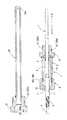
図1及び図2に示すように、シース型温度センサー1は、尾端近傍部に摺動スリーブ2を固着すると共に、該摺動スリーブ2よりも先端側の部位にバネ受部材3を固着している。シース型温度センサー1のそれ自体は、公知のものが使用される。例えば、先端閉塞状とされた金属製又はセラミック製の管体から成るシースの内部に熱電対を内装した「シース熱電対」や、前記と同様のシースの内部に内部導線及び測温用抵抗素子を内装した「シース測温抵抗体」を使用することができる。(Configuration of sheath type temperature sensor)
As shown in FIGS. 1 and 2, the sheath-
摺動スリーブ2は、肉厚の薄い金属製又はセラミック製の筒体の内部に耐熱性の合成樹脂を充填し硬化させており、これにより内部導線(シース熱電対の場合は熱電対素線、シース測温抵抗体の場合は抵抗素子に接続された内部導線)が絶縁保持され、断線しないように固められている。図例の場合、該摺動スリーブ2の尾端から外部導線4が導出され、一端を摺動スリーブ2に固定された可撓性コイル5により外部導線4の外周を保持し保護している。尚、図示のように、摺動スリーブ2の外径は、シース型温度センサー1のシースの外径よりもやや大径に形成されている。 The sliding
バネ受部材3は、金属製の環状体から成り、シース型温度センサー1のシースに外挿されると共に、溶接又はカシメ等により固着されている。 The
前記摺動スリーブ2にはコイルスプリング6が外挿され、該コイルスプリング6の一端はバネ受部材3に接支される。 A
(ハウジング装置の構成部品)
シース型温度センサー1の尾端近傍部を摺動自在に保持するハウジング装置7は、シリンダ8とシールキャップ9とから構成されている。(Components of housing device)
A
シリンダ8は、金属製の筒体により構成され、前記コイルスプリング6を外挿した摺動スリーブ2とバネ受部材3を含むシース型温度センサー1の尾端近傍部を軸方向に移動自在に挿通せしめる内室10を形成している。シリンダ8の先端には金属製の筒手段11が溶接等により固着され、該筒手段11は、シリンダ8から同軸上で同心状に延長されたコネクタ12を構成すると共に、取付手段13を構成する。 The
シールキャップ9は、金属製の椀状体により構成され、前記シリンダ10の尾端部に着脱自在に結合される筒状部14と、前記摺動スリーブ2を摺動自在に保持する摺動孔15を形成した円環部16を備えており、摺動孔15に凹溝を介してOリング等から成るシールリング17を備えている。 The
シールキャップ9の筒状部14と、シリンダ8の尾端部は、相互に着脱自在なネジ手段18a、18bを設けており、螺着方向(締着方向)に対して次第に径を減じるテーパネジを形成することにより気密的に結合される気密結合手段を構成している。尚、図例の場合、シールキャップのネジ手段18aを雌ネジとし、ハウジングのネジ手段18bを雄ネジとしているが、その反対となるように形成しても良い。また、このようなテーパネジにより気密結合手段を構成する他、螺着時に圧縮されるシールリングにより気密結合手段を構成しても良い。 The
(ハウジング装置の組立構成)
摺動スリーブ2からバネ受部材3にかけてコイルスプリング6を外挿した状態で、シース型温度センサー1をシリンダ8の内室10に挿通せしめると共に、摺動スリーブ2をシールキャップ9の摺動孔15に挿通せしめた後、前記ネジ手段18a、18bを介してシリンダ8の尾端開口部をシールキャップ9により閉鎖すると、図2に示すようにハウジング装置7が組み立てられる。(Assembly structure of housing device)
The sheath
この状態で、コイルスプリング6は、バネ受部材3とシールキャップ9の円環部16との間に圧縮状態で介装されているので、シース型温度センサー1が先端方向Fに向けて弾発付勢される。尚、図示の状態においては、シリンダ8の内室10に臨む筒手段11のストッパ部19に対してバネ受部材3が当接し、シース型温度センサー1の先端方向への跳び出しを阻止している。 In this state, the
そこで、シース型温度センサー1は、コイルスプリング6に抗して尾端方向Rに向けて移動自在であり、その際、摺動スリーブ2が摺動孔15のシールリング17に密着した状態で滑らかに摺動する。 Therefore, the sheath
(保護管の構成)
図1及び図2に示すように、保護管20は、先端20aを閉塞状とした金属製の管体から構成され、尾端に金属製の筒手段21が溶接等により固着され、該筒手段21は、保護管20から同軸上で同心状に延長されたコネクタ22を構成すると共に、取付手段23を構成する。(Protection tube configuration)
As shown in FIGS. 1 and 2, the
保護管20は、ハウジング装置7の筒手段11に対してコネクタ12、22を介して着脱自在に連結可能とされている。このため、ハウジング装置7のコネクタ12と、保護管20のコネクタ22は、相互に着脱自在なネジ手段24a、24bを設けており、螺着方向(締着方向)に対して次第に径を減じるテーパネジを形成することにより気密的に結合される気密結合手段を構成している。尚、図例の場合、コネクタ12のネジ手段24aを雄ネジとし、コネクタ22のネジ手段24bを雌ネジとしているが、その反対となるように形成しても良い。また、このようなテーパネジにより気密結合手段を構成する他、螺着時に圧縮されるシールリングにより気密結合手段を構成しても良い。 The
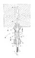
(本発明の第1実施形態)
図3に示す本発明の第1実施形態において、ハウジング装置7の先端に保護管20が取付けた測温装置P1が提供される。前述のように、保護管20に固着した筒手段21のコネクタ22をハウジング装置7における筒手段11のコネクタ12に連結することにより、保護管20がハウジング装置7の同軸上で同心状に延長される。ハウジング装置7から先端方向に延びるシース型温度センサー1は、保護管20に挿入され、コイルスプリング6の弾発付勢力により、シース型温度センサー1の先端を保護管20の先端閉塞部20aに弾接している。(First embodiment of the present invention)
In the first embodiment of the present invention shown in FIG. 3, a temperature measuring device P <b> 1 in which a
そこで、被測温体25に形成された有底の測温孔26に保護管20が挿入される。筒手段21に設けられた取付手段23は、図例の場合、雄ネジ27aを構成しており、測温孔26に形成された雌ネジに螺着され、保護管20の先端が測温孔26の底部28に当接するまで螺入される。この際、相互に螺着される雄ネジ27aと雌ネジは、螺着方向(締着方向)に対して次第に径を減じるテーパネジを形成することにより気密的に結合される気密結合手段を構成している。 Therefore, the
測温中、被測温体25の熱が保護管20を介してシース型温度センサー1に伝達され、シース型温度センサー1の軸方向の熱膨張を生じるが、シース型温度センサー1は、先端を保護管20の先端閉塞部20aに当接したままコイルスプリング6に抗して尾端方向Rに退避自在とされているので、膨張を好適に吸収する。また、測温孔26の内部に生じた高温ガスは、筒手段21と測温孔26の間が気密保持されているので、外部に漏出することはない。因みに、コイルスプリング6及びシールリング17を有するハウジング装置7は、被測温体25の外部に配置されているので、熱影響から解放されている。 During temperature measurement, the heat of the temperature-measured
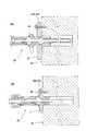
(本発明の第2実施形態)
図4に示す本発明の第2実施形態において、ハウジング装置7の先端に保護管20が取付けない状態で使用される、即ち、ハウジング装置7から先端方向にシース型温度センサー1がそのまま裸状態で延びた測温装置P2が提供される。(Second embodiment of the present invention)
In the second embodiment of the present invention shown in FIG. 4, the
ハウジング装置7の筒手段11に設けられた取付手段13は、図例の場合、雄ネジ29aを構成しており、測温孔26に形成された雌ネジに螺着される。この際、相互に螺着される雄ネジ29aと雌ネジは、螺着方向(締着方向)に対して次第に径を減じるテーパネジを形成することにより気密的に結合される気密結合手段を構成している。シース型温度センサー1は、コイルスプリング6により先端方向に向けて弾発付勢されており、先端を測温孔26の底部28に弾接される。 In the illustrated example, the attachment means 13 provided on the cylinder means 11 of the
測温中、被測温体25の熱がシース型温度センサー1に伝達され、シース型温度センサー1の軸方向の熱膨張を生じるが、シース型温度センサー1は、先端を測温孔26の底部28に当接したままコイルスプリング6に抗して尾端方向Rに退避自在とされているので、膨張を好適に吸収する。測温孔26の内部に生じた高温ガスは、筒手段11測温孔26の間が気密保持されているので、外部に漏出することはない。該筒手段11の内部からシリンダ8に進入する高温ガスは、シリンダ8とシールキャップ9の間をテーパネジ手段18a、18bにより気密保持され、シールキャップ9と摺動スリーブ2の間をシールリング17により気密保持されているので、内室10から外部に漏出することはない。因みに、コイルスプリング6及びシールリング17を有するハウジング装置7は、被測温体25の外部に配置されているので、熱影響から解放されている。 During temperature measurement, the heat of the temperature-measuring
(取付手段の変形実施例)
図5は、取付手段の変形実施例を示しており、図5(A)は、上記測温装置P1における取付手段23の変形実施例を示し、図5(B)は上記測温装置P2における取付手段13の変形実施例を示しいる。(Modified embodiment of mounting means)
FIG. 5 shows a modified embodiment of the attaching means, FIG. 5 (A) shows a modified embodiment of the attaching means 23 in the temperature measuring device P1, and FIG. 5 (B) shows the temperature measuring device P2. A modified embodiment of the attachment means 13 is shown.
図5(A)に示すように、ハウジング装置7に保護管20を組み付けた測温装置P1の場合、取付手段23は、筒手段21に設けたフランジ27bにより構成し、該フランジ27bをボルト等の固着手段30により被測温体25の外面に固着するように構成することができる。 As shown in FIG. 5A, in the case of the temperature measuring device P1 in which the
図5(B)に示すように、保護管を設けない測温装置P2の場合、取付手段13は、筒手段11に設けたフランジ29bにより構成し、該フランジ29bをボルト等の固着手段30により被測温体25の外面に固着するように構成することができる。 As shown in FIG. 5B, in the case of the temperature measuring device P2 not provided with a protective tube, the attachment means 13 is constituted by a
1 シース型温度センサー
2 摺動スリーブ
3 バネ受部材
6 コイルスプリング
7 ハウジング装置
8 シリンダ
9 シールキャップ
10 内室
11 筒手段
12 コネクタ
13 取付手段
15 摺動孔
17 シールリング
20 保護管
21 筒手段
22 コネクタ
23 取付手段
25 被測温体
26 測温孔DESCRIPTION OF
Claims (3)
Translated fromJapaneseハウジング装置(7)と、該ハウジング装置(7)から先端方向に延びると共に先端(20a)を閉塞状とした保護管(20)を備え、前記ハウジング装置(7)にシース型温度センサー(1)の尾端近傍部を軸方向移動自在に挿入すると共にコイルスプリング(6)を介して先端方向に向けて弾発付勢し、
前記ハウジング装置(7)の先端部と前記保護管(20)の尾端部にそれぞれコネクタ(12)(22)及び取付手段(13)(23)を設け、前記コネクタ(12)(13)を介してハウジング装置(7)と保護管(20)を相互に連結可能に構成することにより、前記ハウジング装置(7)に保護管(20)を連結した保護管付きの測温装置(P1)と、前記ハウジング装置(7)に保護管(20)を連結していない保護管なしの測温装置(P2)を選択的に構成可能としており、
前記保護管付きの測温装置(P1)は、シース型温度センサー(1)の先端を保護管(20)の先端閉塞部(20a)に弾接させた状態で、前記保護管(20)の取付手段(23)を測温孔(26)に取付けることにより該保護管(20)の先端を測温孔(26)の底部(28)に当接し、
前記保護管なしの測温装置(P2)は、前記ハウジング装置(7)の取付手段(13)を測温孔(26)に取付けることによりシース型温度センサー(1)の先端を測温孔(26)の底部(28)に弾接するように構成されて成ることを特徴とする測温装置。The sheath type temperature sensor (1) is inserted into the bottomed temperature measurement hole (26) formed in the temperature measurement object (25), and the tip of the sheath type temperature sensor (1) is directly or indirectly connected to the temperature measurement hole ( In a device for measuring temperature by abutting against the bottom (28) of 26),
A housing device (7) and a protective tube (20) extending in the distal direction from the housing device (7) and having the distal end (20a) closed, the sheath temperature sensor (1) in the housing device (7) And inserted in the axial direction of the vicinity of the tail end of the swaying end, and elastically biased toward the tip end direction via the coil spring (6) ,
Connectors (12), (22) and attachment means (13), (23) are provided at the tip of the housing device (7) and the tail end of the protective tube (20), respectively, and the connectors (12), (13) The housing device (7) and the protective tube (20) are configured to be mutually connectable, and the temperature measuring device (P1) with the protective tube connecting the protective tube (20) to the housing device (7). The temperature measuring device (P2) without a protective tube in which the protective tube (20) is not connected to the housing device (7) can be selectively configured ,
The temperature measuring device (P1) with the protective tube is in a state where the distal end of the sheath type temperature sensor (1) is in elastic contact with the distal end blocking portion (20a) of the protective tube (20). By attaching the mounting means (23) to the temperature measuring hole (26), the tip of the protective tube (20) is brought into contact with the bottom (28) of the temperature measuring hole (26),
The temperature measuring device (P2) without the protective tube is attached to the temperature measuring hole (26) by attaching the mounting means (13) of the housing device (7) to the temperature measuring hole (26). A temperature measuring device configured to elasticallycontact the bottom (28) of 26) .
前記ハウジング装置(7)は、前記摺動スリーブ(2)とバネ受部材(3)を含むシース型温度センサー(1)の尾端近傍部を軸方向に移動自在に挿通せしめる内室(10)を形成するシリンダ(8)と、前記内室(10)に設けられたコイルスプリング(6)と、前記シリンダ(8)の尾端部に着脱自在に取付けられ該シリンダ(8)の尾端開口部を気密的に閉鎖するシールキャップ(9)とを備え、
前記シールキャップ(9)は、前記シース型温度センサー(1)の摺動スリーブ(2)を摺動自在に保持する摺動孔(15)を形成すると共に、該摺動孔(15)と摺動スリーブ(2)の間を気密的に保持するシールリング(17)を備え、該シールキャップ(9)と前記バネ受部材(3)の間に前記コイルスプリング(6)を介装せしめることによりシース型温度センサー(1)を先端方向に向けて弾発付勢するように構成されて成ることを特徴とする請求項1に記載の測温装置。The sheath-type temperature sensor (1) has the sliding sleeve (2) fixed to the vicinity of the tail end, and the spring receiving member (3) is fixed to the tip side of the sliding sleeve (2),
The housing device (7) includes an inner chamber (10) in which a portion near the tail end of the sheath-type temperature sensor (1) including the sliding sleeve (2) and a spring receiving member (3) is movably inserted in the axial direction. A cylinder spring (6), a coil spring (6) provided in the inner chamber (10), and a tail end opening of the cylinder (8) removably attached to the tail end of the cylinder (8). A seal cap (9) for hermetically closing the part,
The seal cap (9) forms a sliding hole (15) that slidably holds the sliding sleeve (2) of the sheath type temperature sensor (1), and slides with the sliding hole (15). A seal ring (17) that hermetically holds the moving sleeve (2), and the coil spring (6) is interposed between the seal cap (9) and the spring receiving member (3). The temperature measuring device according to claim 1, wherein thesheath type temperature sensor (1) is configured to elastically urge the sheath type temperature sensor (1) toward a distal direction .
Priority Applications (1)
| Application Number | Priority Date | Filing Date | Title |
|---|---|---|---|
| JP2004274330AJP4698190B2 (en) | 2004-09-22 | 2004-09-22 | Temperature measuring device |
Applications Claiming Priority (1)
| Application Number | Priority Date | Filing Date | Title |
|---|---|---|---|
| JP2004274330AJP4698190B2 (en) | 2004-09-22 | 2004-09-22 | Temperature measuring device |
Publications (2)
| Publication Number | Publication Date |
|---|---|
| JP2006090762A JP2006090762A (en) | 2006-04-06 |
| JP4698190B2true JP4698190B2 (en) | 2011-06-08 |
Family
ID=36231909
Family Applications (1)
| Application Number | Title | Priority Date | Filing Date |
|---|---|---|---|
| JP2004274330AExpired - LifetimeJP4698190B2 (en) | 2004-09-22 | 2004-09-22 | Temperature measuring device |
Country Status (1)
| Country | Link |
|---|---|
| JP (1) | JP4698190B2 (en) |
Cited By (1)
| Publication number | Priority date | Publication date | Assignee | Title |
|---|---|---|---|---|
| KR20200057876A (en) | 2018-11-16 | 2020-05-27 | 주식회사 포스코 | Temperature measuring equipment of slab bottom surface |
Families Citing this family (370)
| Publication number | Priority date | Publication date | Assignee | Title |
|---|---|---|---|---|
| JP2008128694A (en)* | 2006-11-17 | 2008-06-05 | Yamari Sangyo Kk | Thermometric sensor and its installation method |
| US7874726B2 (en) | 2007-05-24 | 2011-01-25 | Asm America, Inc. | Thermocouple |
| US20090052498A1 (en)* | 2007-08-24 | 2009-02-26 | Asm America, Inc. | Thermocouple |
| US7946762B2 (en) | 2008-06-17 | 2011-05-24 | Asm America, Inc. | Thermocouple |
| US10378106B2 (en) | 2008-11-14 | 2019-08-13 | Asm Ip Holding B.V. | Method of forming insulation film by modified PEALD |
| US8262287B2 (en) | 2008-12-08 | 2012-09-11 | Asm America, Inc. | Thermocouple |
| US9394608B2 (en) | 2009-04-06 | 2016-07-19 | Asm America, Inc. | Semiconductor processing reactor and components thereof |
| US9297705B2 (en) | 2009-05-06 | 2016-03-29 | Asm America, Inc. | Smart temperature measuring device |
| US8382370B2 (en) | 2009-05-06 | 2013-02-26 | Asm America, Inc. | Thermocouple assembly with guarded thermocouple junction |
| US8100583B2 (en) | 2009-05-06 | 2012-01-24 | Asm America, Inc. | Thermocouple |
| US8802201B2 (en) | 2009-08-14 | 2014-08-12 | Asm America, Inc. | Systems and methods for thin-film deposition of metal oxides using excited nitrogen-oxygen species |
| KR101159741B1 (en)* | 2009-09-28 | 2012-06-28 | 현대제철 주식회사 | Apparatus for measuring surface temperature of slab |
| US9312155B2 (en) | 2011-06-06 | 2016-04-12 | Asm Japan K.K. | High-throughput semiconductor-processing apparatus equipped with multiple dual-chamber modules |
| US10364496B2 (en) | 2011-06-27 | 2019-07-30 | Asm Ip Holding B.V. | Dual section module having shared and unshared mass flow controllers |
| US10854498B2 (en) | 2011-07-15 | 2020-12-01 | Asm Ip Holding B.V. | Wafer-supporting device and method for producing same |
| US20130023129A1 (en) | 2011-07-20 | 2013-01-24 | Asm America, Inc. | Pressure transmitter for a semiconductor processing environment |
| US9017481B1 (en) | 2011-10-28 | 2015-04-28 | Asm America, Inc. | Process feed management for semiconductor substrate processing |
| US9659799B2 (en) | 2012-08-28 | 2017-05-23 | Asm Ip Holding B.V. | Systems and methods for dynamic semiconductor process scheduling |
| US10714315B2 (en) | 2012-10-12 | 2020-07-14 | Asm Ip Holdings B.V. | Semiconductor reaction chamber showerhead |
| US20160376700A1 (en) | 2013-02-01 | 2016-12-29 | Asm Ip Holding B.V. | System for treatment of deposition reactor |
| US9484191B2 (en) | 2013-03-08 | 2016-11-01 | Asm Ip Holding B.V. | Pulsed remote plasma method and system |
| USD702188S1 (en) | 2013-03-08 | 2014-04-08 | Asm Ip Holding B.V. | Thermocouple |
| US9589770B2 (en) | 2013-03-08 | 2017-03-07 | Asm Ip Holding B.V. | Method and systems for in-situ formation of intermediate reactive species |
| US9341522B2 (en)* | 2013-05-01 | 2016-05-17 | Rosemount Inc. | Spring-loaded temperature sensor |
| US9240412B2 (en) | 2013-09-27 | 2016-01-19 | Asm Ip Holding B.V. | Semiconductor structure and device and methods of forming same using selective epitaxial process |
| KR101623382B1 (en)* | 2014-01-06 | 2016-05-23 | 두산중공업 주식회사 | Thermocouple of generator water cooling coil and Temperature measurement using the same |
| US10683571B2 (en) | 2014-02-25 | 2020-06-16 | Asm Ip Holding B.V. | Gas supply manifold and method of supplying gases to chamber using same |
| US10167557B2 (en) | 2014-03-18 | 2019-01-01 | Asm Ip Holding B.V. | Gas distribution system, reactor including the system, and methods of using the same |
| US11015245B2 (en) | 2014-03-19 | 2021-05-25 | Asm Ip Holding B.V. | Gas-phase reactor and system having exhaust plenum and components thereof |
| US10858737B2 (en) | 2014-07-28 | 2020-12-08 | Asm Ip Holding B.V. | Showerhead assembly and components thereof |
| US9890456B2 (en) | 2014-08-21 | 2018-02-13 | Asm Ip Holding B.V. | Method and system for in situ formation of gas-phase compounds |
| US10941490B2 (en) | 2014-10-07 | 2021-03-09 | Asm Ip Holding B.V. | Multiple temperature range susceptor, assembly, reactor and system including the susceptor, and methods of using the same |
| US9657845B2 (en) | 2014-10-07 | 2017-05-23 | Asm Ip Holding B.V. | Variable conductance gas distribution apparatus and method |
| KR102263121B1 (en) | 2014-12-22 | 2021-06-09 | 에이에스엠 아이피 홀딩 비.브이. | Semiconductor device and manufacuring method thereof |
| US10529542B2 (en) | 2015-03-11 | 2020-01-07 | Asm Ip Holdings B.V. | Cross-flow reactor and method |
| US10276355B2 (en) | 2015-03-12 | 2019-04-30 | Asm Ip Holding B.V. | Multi-zone reactor, system including the reactor, and method of using the same |
| US10458018B2 (en) | 2015-06-26 | 2019-10-29 | Asm Ip Holding B.V. | Structures including metal carbide material, devices including the structures, and methods of forming same |
| CN104949765B (en)* | 2015-06-30 | 2018-02-06 | 湖南崇德工业科技有限公司 | A kind of sliding bearing temperature element retaining mechanism |
| US10600673B2 (en) | 2015-07-07 | 2020-03-24 | Asm Ip Holding B.V. | Magnetic susceptor to baseplate seal |
| US9960072B2 (en) | 2015-09-29 | 2018-05-01 | Asm Ip Holding B.V. | Variable adjustment for precise matching of multiple chamber cavity housings |
| US10211308B2 (en) | 2015-10-21 | 2019-02-19 | Asm Ip Holding B.V. | NbMC layers |
| US10322384B2 (en) | 2015-11-09 | 2019-06-18 | Asm Ip Holding B.V. | Counter flow mixer for process chamber |
| US11139308B2 (en) | 2015-12-29 | 2021-10-05 | Asm Ip Holding B.V. | Atomic layer deposition of III-V compounds to form V-NAND devices |
| US10468251B2 (en) | 2016-02-19 | 2019-11-05 | Asm Ip Holding B.V. | Method for forming spacers using silicon nitride film for spacer-defined multiple patterning |
| US10529554B2 (en) | 2016-02-19 | 2020-01-07 | Asm Ip Holding B.V. | Method for forming silicon nitride film selectively on sidewalls or flat surfaces of trenches |
| US10501866B2 (en) | 2016-03-09 | 2019-12-10 | Asm Ip Holding B.V. | Gas distribution apparatus for improved film uniformity in an epitaxial system |
| US10343920B2 (en) | 2016-03-18 | 2019-07-09 | Asm Ip Holding B.V. | Aligned carbon nanotubes |
| US9892913B2 (en) | 2016-03-24 | 2018-02-13 | Asm Ip Holding B.V. | Radial and thickness control via biased multi-port injection settings |
| US10865475B2 (en) | 2016-04-21 | 2020-12-15 | Asm Ip Holding B.V. | Deposition of metal borides and silicides |
| US10190213B2 (en) | 2016-04-21 | 2019-01-29 | Asm Ip Holding B.V. | Deposition of metal borides |
| US10032628B2 (en) | 2016-05-02 | 2018-07-24 | Asm Ip Holding B.V. | Source/drain performance through conformal solid state doping |
| US10367080B2 (en) | 2016-05-02 | 2019-07-30 | Asm Ip Holding B.V. | Method of forming a germanium oxynitride film |
| JP6754218B2 (en)* | 2016-05-10 | 2020-09-09 | 株式会社テイエルブイ | Sensor device and its installation confirmation method |
| JP6775997B2 (en)* | 2016-05-13 | 2020-10-28 | 株式会社エンプラス | Socket for electrical components |
| KR102592471B1 (en) | 2016-05-17 | 2023-10-20 | 에이에스엠 아이피 홀딩 비.브이. | Method of forming metal interconnection and method of fabricating semiconductor device using the same |
| US10388509B2 (en) | 2016-06-28 | 2019-08-20 | Asm Ip Holding B.V. | Formation of epitaxial layers via dislocation filtering |
| US9859151B1 (en) | 2016-07-08 | 2018-01-02 | Asm Ip Holding B.V. | Selective film deposition method to form air gaps |
| US10612137B2 (en) | 2016-07-08 | 2020-04-07 | Asm Ip Holdings B.V. | Organic reactants for atomic layer deposition |
| US10714385B2 (en) | 2016-07-19 | 2020-07-14 | Asm Ip Holding B.V. | Selective deposition of tungsten |
| US10381226B2 (en) | 2016-07-27 | 2019-08-13 | Asm Ip Holding B.V. | Method of processing substrate |
| US10395919B2 (en) | 2016-07-28 | 2019-08-27 | Asm Ip Holding B.V. | Method and apparatus for filling a gap |
| KR102532607B1 (en) | 2016-07-28 | 2023-05-15 | 에이에스엠 아이피 홀딩 비.브이. | Substrate processing apparatus and method of operating the same |
| US9812320B1 (en) | 2016-07-28 | 2017-11-07 | Asm Ip Holding B.V. | Method and apparatus for filling a gap |
| US9887082B1 (en) | 2016-07-28 | 2018-02-06 | Asm Ip Holding B.V. | Method and apparatus for filling a gap |
| KR102613349B1 (en) | 2016-08-25 | 2023-12-14 | 에이에스엠 아이피 홀딩 비.브이. | Exhaust apparatus and substrate processing apparatus and thin film fabricating method using the same |
| US10410943B2 (en) | 2016-10-13 | 2019-09-10 | Asm Ip Holding B.V. | Method for passivating a surface of a semiconductor and related systems |
| US10643826B2 (en) | 2016-10-26 | 2020-05-05 | Asm Ip Holdings B.V. | Methods for thermally calibrating reaction chambers |
| US11532757B2 (en) | 2016-10-27 | 2022-12-20 | Asm Ip Holding B.V. | Deposition of charge trapping layers |
| US10229833B2 (en) | 2016-11-01 | 2019-03-12 | Asm Ip Holding B.V. | Methods for forming a transition metal nitride film on a substrate by atomic layer deposition and related semiconductor device structures |
| US10643904B2 (en) | 2016-11-01 | 2020-05-05 | Asm Ip Holdings B.V. | Methods for forming a semiconductor device and related semiconductor device structures |
| US10435790B2 (en) | 2016-11-01 | 2019-10-08 | Asm Ip Holding B.V. | Method of subatmospheric plasma-enhanced ALD using capacitively coupled electrodes with narrow gap |
| US10714350B2 (en) | 2016-11-01 | 2020-07-14 | ASM IP Holdings, B.V. | Methods for forming a transition metal niobium nitride film on a substrate by atomic layer deposition and related semiconductor device structures |
| US10134757B2 (en) | 2016-11-07 | 2018-11-20 | Asm Ip Holding B.V. | Method of processing a substrate and a device manufactured by using the method |
| KR102546317B1 (en) | 2016-11-15 | 2023-06-21 | 에이에스엠 아이피 홀딩 비.브이. | Gas supply unit and substrate processing apparatus including the same |
| US10340135B2 (en) | 2016-11-28 | 2019-07-02 | Asm Ip Holding B.V. | Method of topologically restricted plasma-enhanced cyclic deposition of silicon or metal nitride |
| KR102762543B1 (en) | 2016-12-14 | 2025-02-05 | 에이에스엠 아이피 홀딩 비.브이. | Substrate processing apparatus |
| US11447861B2 (en) | 2016-12-15 | 2022-09-20 | Asm Ip Holding B.V. | Sequential infiltration synthesis apparatus and a method of forming a patterned structure |
| US11581186B2 (en) | 2016-12-15 | 2023-02-14 | Asm Ip Holding B.V. | Sequential infiltration synthesis apparatus |
| KR102700194B1 (en) | 2016-12-19 | 2024-08-28 | 에이에스엠 아이피 홀딩 비.브이. | Substrate processing apparatus |
| US10269558B2 (en) | 2016-12-22 | 2019-04-23 | Asm Ip Holding B.V. | Method of forming a structure on a substrate |
| US10867788B2 (en) | 2016-12-28 | 2020-12-15 | Asm Ip Holding B.V. | Method of forming a structure on a substrate |
| US11390950B2 (en) | 2017-01-10 | 2022-07-19 | Asm Ip Holding B.V. | Reactor system and method to reduce residue buildup during a film deposition process |
| US10655221B2 (en) | 2017-02-09 | 2020-05-19 | Asm Ip Holding B.V. | Method for depositing oxide film by thermal ALD and PEALD |
| US10468261B2 (en) | 2017-02-15 | 2019-11-05 | Asm Ip Holding B.V. | Methods for forming a metallic film on a substrate by cyclical deposition and related semiconductor device structures |
| US10529563B2 (en) | 2017-03-29 | 2020-01-07 | Asm Ip Holdings B.V. | Method for forming doped metal oxide films on a substrate by cyclical deposition and related semiconductor device structures |
| US10283353B2 (en) | 2017-03-29 | 2019-05-07 | Asm Ip Holding B.V. | Method of reforming insulating film deposited on substrate with recess pattern |
| KR102457289B1 (en) | 2017-04-25 | 2022-10-21 | 에이에스엠 아이피 홀딩 비.브이. | Method for depositing a thin film and manufacturing a semiconductor device |
| US10892156B2 (en) | 2017-05-08 | 2021-01-12 | Asm Ip Holding B.V. | Methods for forming a silicon nitride film on a substrate and related semiconductor device structures |
| US10770286B2 (en) | 2017-05-08 | 2020-09-08 | Asm Ip Holdings B.V. | Methods for selectively forming a silicon nitride film on a substrate and related semiconductor device structures |
| US10446393B2 (en) | 2017-05-08 | 2019-10-15 | Asm Ip Holding B.V. | Methods for forming silicon-containing epitaxial layers and related semiconductor device structures |
| US10504742B2 (en) | 2017-05-31 | 2019-12-10 | Asm Ip Holding B.V. | Method of atomic layer etching using hydrogen plasma |
| US10886123B2 (en) | 2017-06-02 | 2021-01-05 | Asm Ip Holding B.V. | Methods for forming low temperature semiconductor layers and related semiconductor device structures |
| KR200487342Y1 (en)* | 2017-06-16 | 2018-09-06 | 한국남부발전(주) | Thermocouple assmbly for measuring temperature of gas turbine |
| US12040200B2 (en) | 2017-06-20 | 2024-07-16 | Asm Ip Holding B.V. | Semiconductor processing apparatus and methods for calibrating a semiconductor processing apparatus |
| US11306395B2 (en) | 2017-06-28 | 2022-04-19 | Asm Ip Holding B.V. | Methods for depositing a transition metal nitride film on a substrate by atomic layer deposition and related deposition apparatus |
| US10685834B2 (en) | 2017-07-05 | 2020-06-16 | Asm Ip Holdings B.V. | Methods for forming a silicon germanium tin layer and related semiconductor device structures |
| KR20190009245A (en) | 2017-07-18 | 2019-01-28 | 에이에스엠 아이피 홀딩 비.브이. | Methods for forming a semiconductor device structure and related semiconductor device structures |
| US11018002B2 (en) | 2017-07-19 | 2021-05-25 | Asm Ip Holding B.V. | Method for selectively depositing a Group IV semiconductor and related semiconductor device structures |
| US10541333B2 (en) | 2017-07-19 | 2020-01-21 | Asm Ip Holding B.V. | Method for depositing a group IV semiconductor and related semiconductor device structures |
| US11374112B2 (en) | 2017-07-19 | 2022-06-28 | Asm Ip Holding B.V. | Method for depositing a group IV semiconductor and related semiconductor device structures |
| US10312055B2 (en) | 2017-07-26 | 2019-06-04 | Asm Ip Holding B.V. | Method of depositing film by PEALD using negative bias |
| US10590535B2 (en) | 2017-07-26 | 2020-03-17 | Asm Ip Holdings B.V. | Chemical treatment, deposition and/or infiltration apparatus and method for using the same |
| US10605530B2 (en) | 2017-07-26 | 2020-03-31 | Asm Ip Holding B.V. | Assembly of a liner and a flange for a vertical furnace as well as the liner and the vertical furnace |
| TWI815813B (en) | 2017-08-04 | 2023-09-21 | 荷蘭商Asm智慧財產控股公司 | Showerhead assembly for distributing a gas within a reaction chamber |
| US10692741B2 (en) | 2017-08-08 | 2020-06-23 | Asm Ip Holdings B.V. | Radiation shield |
| US10770336B2 (en) | 2017-08-08 | 2020-09-08 | Asm Ip Holding B.V. | Substrate lift mechanism and reactor including same |
| US11769682B2 (en) | 2017-08-09 | 2023-09-26 | Asm Ip Holding B.V. | Storage apparatus for storing cassettes for substrates and processing apparatus equipped therewith |
| US10249524B2 (en) | 2017-08-09 | 2019-04-02 | Asm Ip Holding B.V. | Cassette holder assembly for a substrate cassette and holding member for use in such assembly |
| US11139191B2 (en) | 2017-08-09 | 2021-10-05 | Asm Ip Holding B.V. | Storage apparatus for storing cassettes for substrates and processing apparatus equipped therewith |
| USD900036S1 (en) | 2017-08-24 | 2020-10-27 | Asm Ip Holding B.V. | Heater electrical connector and adapter |
| US11830730B2 (en) | 2017-08-29 | 2023-11-28 | Asm Ip Holding B.V. | Layer forming method and apparatus |
| US11295980B2 (en) | 2017-08-30 | 2022-04-05 | Asm Ip Holding B.V. | Methods for depositing a molybdenum metal film over a dielectric surface of a substrate by a cyclical deposition process and related semiconductor device structures |
| US11056344B2 (en) | 2017-08-30 | 2021-07-06 | Asm Ip Holding B.V. | Layer forming method |
| KR102491945B1 (en) | 2017-08-30 | 2023-01-26 | 에이에스엠 아이피 홀딩 비.브이. | Substrate processing apparatus |
| KR102401446B1 (en) | 2017-08-31 | 2022-05-24 | 에이에스엠 아이피 홀딩 비.브이. | Substrate processing apparatus |
| US10607895B2 (en) | 2017-09-18 | 2020-03-31 | Asm Ip Holdings B.V. | Method for forming a semiconductor device structure comprising a gate fill metal |
| KR102630301B1 (en) | 2017-09-21 | 2024-01-29 | 에이에스엠 아이피 홀딩 비.브이. | Method of sequential infiltration synthesis treatment of infiltrateable material and structures and devices formed using same |
| US10844484B2 (en) | 2017-09-22 | 2020-11-24 | Asm Ip Holding B.V. | Apparatus for dispensing a vapor phase reactant to a reaction chamber and related methods |
| US10658205B2 (en) | 2017-09-28 | 2020-05-19 | Asm Ip Holdings B.V. | Chemical dispensing apparatus and methods for dispensing a chemical to a reaction chamber |
| US10403504B2 (en) | 2017-10-05 | 2019-09-03 | Asm Ip Holding B.V. | Method for selectively depositing a metallic film on a substrate |
| US10319588B2 (en) | 2017-10-10 | 2019-06-11 | Asm Ip Holding B.V. | Method for depositing a metal chalcogenide on a substrate by cyclical deposition |
| US10923344B2 (en) | 2017-10-30 | 2021-02-16 | Asm Ip Holding B.V. | Methods for forming a semiconductor structure and related semiconductor structures |
| KR102443047B1 (en) | 2017-11-16 | 2022-09-14 | 에이에스엠 아이피 홀딩 비.브이. | Method of processing a substrate and a device manufactured by the same |
| US10910262B2 (en) | 2017-11-16 | 2021-02-02 | Asm Ip Holding B.V. | Method of selectively depositing a capping layer structure on a semiconductor device structure |
| US11022879B2 (en) | 2017-11-24 | 2021-06-01 | Asm Ip Holding B.V. | Method of forming an enhanced unexposed photoresist layer |
| JP7214724B2 (en) | 2017-11-27 | 2023-01-30 | エーエスエム アイピー ホールディング ビー.ブイ. | Storage device for storing wafer cassettes used in batch furnaces |
| US11639811B2 (en) | 2017-11-27 | 2023-05-02 | Asm Ip Holding B.V. | Apparatus including a clean mini environment |
| US10290508B1 (en) | 2017-12-05 | 2019-05-14 | Asm Ip Holding B.V. | Method for forming vertical spacers for spacer-defined patterning |
| US10872771B2 (en) | 2018-01-16 | 2020-12-22 | Asm Ip Holding B. V. | Method for depositing a material film on a substrate within a reaction chamber by a cyclical deposition process and related device structures |
| TWI799494B (en) | 2018-01-19 | 2023-04-21 | 荷蘭商Asm 智慧財產控股公司 | Deposition method |
| US11482412B2 (en) | 2018-01-19 | 2022-10-25 | Asm Ip Holding B.V. | Method for depositing a gap-fill layer by plasma-assisted deposition |
| USD903477S1 (en) | 2018-01-24 | 2020-12-01 | Asm Ip Holdings B.V. | Metal clamp |
| US11018047B2 (en) | 2018-01-25 | 2021-05-25 | Asm Ip Holding B.V. | Hybrid lift pin |
| US10535516B2 (en) | 2018-02-01 | 2020-01-14 | Asm Ip Holdings B.V. | Method for depositing a semiconductor structure on a surface of a substrate and related semiconductor structures |
| USD880437S1 (en) | 2018-02-01 | 2020-04-07 | Asm Ip Holding B.V. | Gas supply plate for semiconductor manufacturing apparatus |
| US11081345B2 (en) | 2018-02-06 | 2021-08-03 | Asm Ip Holding B.V. | Method of post-deposition treatment for silicon oxide film |
| KR102657269B1 (en) | 2018-02-14 | 2024-04-16 | 에이에스엠 아이피 홀딩 비.브이. | Method for depositing a ruthenium-containing film on a substrate by a cyclic deposition process |
| US10896820B2 (en) | 2018-02-14 | 2021-01-19 | Asm Ip Holding B.V. | Method for depositing a ruthenium-containing film on a substrate by a cyclical deposition process |
| US10731249B2 (en) | 2018-02-15 | 2020-08-04 | Asm Ip Holding B.V. | Method of forming a transition metal containing film on a substrate by a cyclical deposition process, a method for supplying a transition metal halide compound to a reaction chamber, and related vapor deposition apparatus |
| US10658181B2 (en) | 2018-02-20 | 2020-05-19 | Asm Ip Holding B.V. | Method of spacer-defined direct patterning in semiconductor fabrication |
| KR102636427B1 (en) | 2018-02-20 | 2024-02-13 | 에이에스엠 아이피 홀딩 비.브이. | Substrate processing method and apparatus |
| US10975470B2 (en) | 2018-02-23 | 2021-04-13 | Asm Ip Holding B.V. | Apparatus for detecting or monitoring for a chemical precursor in a high temperature environment |
| JP7460326B2 (en)* | 2018-02-27 | 2024-04-02 | 三菱重工業株式会社 | temperature measuring device |
| US11473195B2 (en) | 2018-03-01 | 2022-10-18 | Asm Ip Holding B.V. | Semiconductor processing apparatus and a method for processing a substrate |
| US11629406B2 (en) | 2018-03-09 | 2023-04-18 | Asm Ip Holding B.V. | Semiconductor processing apparatus comprising one or more pyrometers for measuring a temperature of a substrate during transfer of the substrate |
| US11114283B2 (en) | 2018-03-16 | 2021-09-07 | Asm Ip Holding B.V. | Reactor, system including the reactor, and methods of manufacturing and using same |
| KR102646467B1 (en) | 2018-03-27 | 2024-03-11 | 에이에스엠 아이피 홀딩 비.브이. | Method of forming an electrode on a substrate and a semiconductor device structure including an electrode |
| US10510536B2 (en) | 2018-03-29 | 2019-12-17 | Asm Ip Holding B.V. | Method of depositing a co-doped polysilicon film on a surface of a substrate within a reaction chamber |
| US11230766B2 (en) | 2018-03-29 | 2022-01-25 | Asm Ip Holding B.V. | Substrate processing apparatus and method |
| US11088002B2 (en) | 2018-03-29 | 2021-08-10 | Asm Ip Holding B.V. | Substrate rack and a substrate processing system and method |
| KR102501472B1 (en) | 2018-03-30 | 2023-02-20 | 에이에스엠 아이피 홀딩 비.브이. | Substrate processing method |
| KR102600229B1 (en) | 2018-04-09 | 2023-11-10 | 에이에스엠 아이피 홀딩 비.브이. | Substrate supporting device, substrate processing apparatus including the same and substrate processing method |
| TWI843623B (en) | 2018-05-08 | 2024-05-21 | 荷蘭商Asm Ip私人控股有限公司 | Methods for depositing an oxide film on a substrate by a cyclical deposition process and related device structures |
| US12025484B2 (en) | 2018-05-08 | 2024-07-02 | Asm Ip Holding B.V. | Thin film forming method |
| US12272527B2 (en) | 2018-05-09 | 2025-04-08 | Asm Ip Holding B.V. | Apparatus for use with hydrogen radicals and method of using same |
| KR20190129718A (en) | 2018-05-11 | 2019-11-20 | 에이에스엠 아이피 홀딩 비.브이. | Methods for forming a doped metal carbide film on a substrate and related semiconductor device structures |
| KR102596988B1 (en) | 2018-05-28 | 2023-10-31 | 에이에스엠 아이피 홀딩 비.브이. | Method of processing a substrate and a device manufactured by the same |
| US11718913B2 (en) | 2018-06-04 | 2023-08-08 | Asm Ip Holding B.V. | Gas distribution system and reactor system including same |
| TWI840362B (en) | 2018-06-04 | 2024-05-01 | 荷蘭商Asm Ip私人控股有限公司 | Wafer handling chamber with moisture reduction |
| US11286562B2 (en) | 2018-06-08 | 2022-03-29 | Asm Ip Holding B.V. | Gas-phase chemical reactor and method of using same |
| US10797133B2 (en) | 2018-06-21 | 2020-10-06 | Asm Ip Holding B.V. | Method for depositing a phosphorus doped silicon arsenide film and related semiconductor device structures |
| KR102568797B1 (en) | 2018-06-21 | 2023-08-21 | 에이에스엠 아이피 홀딩 비.브이. | Substrate processing system |
| KR102854019B1 (en) | 2018-06-27 | 2025-09-02 | 에이에스엠 아이피 홀딩 비.브이. | Periodic deposition method for forming a metal-containing material and films and structures comprising the metal-containing material |
| TWI815915B (en) | 2018-06-27 | 2023-09-21 | 荷蘭商Asm Ip私人控股有限公司 | Cyclic deposition methods for forming metal-containing material and films and structures including the metal-containing material |
| US10612136B2 (en) | 2018-06-29 | 2020-04-07 | ASM IP Holding, B.V. | Temperature-controlled flange and reactor system including same |
| KR102686758B1 (en) | 2018-06-29 | 2024-07-18 | 에이에스엠 아이피 홀딩 비.브이. | Method for depositing a thin film and manufacturing a semiconductor device |
| US10755922B2 (en) | 2018-07-03 | 2020-08-25 | Asm Ip Holding B.V. | Method for depositing silicon-free carbon-containing film as gap-fill layer by pulse plasma-assisted deposition |
| US10388513B1 (en) | 2018-07-03 | 2019-08-20 | Asm Ip Holding B.V. | Method for depositing silicon-free carbon-containing film as gap-fill layer by pulse plasma-assisted deposition |
| US10767789B2 (en) | 2018-07-16 | 2020-09-08 | Asm Ip Holding B.V. | Diaphragm valves, valve components, and methods for forming valve components |
| US10483099B1 (en) | 2018-07-26 | 2019-11-19 | Asm Ip Holding B.V. | Method for forming thermally stable organosilicon polymer film |
| US11053591B2 (en) | 2018-08-06 | 2021-07-06 | Asm Ip Holding B.V. | Multi-port gas injection system and reactor system including same |
| US10883175B2 (en) | 2018-08-09 | 2021-01-05 | Asm Ip Holding B.V. | Vertical furnace for processing substrates and a liner for use therein |
| US10829852B2 (en) | 2018-08-16 | 2020-11-10 | Asm Ip Holding B.V. | Gas distribution device for a wafer processing apparatus |
| US11430674B2 (en) | 2018-08-22 | 2022-08-30 | Asm Ip Holding B.V. | Sensor array, apparatus for dispensing a vapor phase reactant to a reaction chamber and related methods |
| US11024523B2 (en) | 2018-09-11 | 2021-06-01 | Asm Ip Holding B.V. | Substrate processing apparatus and method |
| KR102707956B1 (en) | 2018-09-11 | 2024-09-19 | 에이에스엠 아이피 홀딩 비.브이. | Method for deposition of a thin film |
| US11049751B2 (en) | 2018-09-14 | 2021-06-29 | Asm Ip Holding B.V. | Cassette supply system to store and handle cassettes and processing apparatus equipped therewith |
| CN110970344B (en) | 2018-10-01 | 2024-10-25 | Asmip控股有限公司 | Substrate holding apparatus, system comprising the same and method of using the same |
| US11232963B2 (en) | 2018-10-03 | 2022-01-25 | Asm Ip Holding B.V. | Substrate processing apparatus and method |
| KR102592699B1 (en) | 2018-10-08 | 2023-10-23 | 에이에스엠 아이피 홀딩 비.브이. | Substrate support unit and apparatuses for depositing thin film and processing the substrate including the same |
| US10847365B2 (en) | 2018-10-11 | 2020-11-24 | Asm Ip Holding B.V. | Method of forming conformal silicon carbide film by cyclic CVD |
| US10811256B2 (en) | 2018-10-16 | 2020-10-20 | Asm Ip Holding B.V. | Method for etching a carbon-containing feature |
| KR102605121B1 (en) | 2018-10-19 | 2023-11-23 | 에이에스엠 아이피 홀딩 비.브이. | Substrate processing apparatus and substrate processing method |
| KR102546322B1 (en) | 2018-10-19 | 2023-06-21 | 에이에스엠 아이피 홀딩 비.브이. | Substrate processing apparatus and substrate processing method |
| USD948463S1 (en) | 2018-10-24 | 2022-04-12 | Asm Ip Holding B.V. | Susceptor for semiconductor substrate supporting apparatus |
| US10381219B1 (en) | 2018-10-25 | 2019-08-13 | Asm Ip Holding B.V. | Methods for forming a silicon nitride film |
| US12378665B2 (en) | 2018-10-26 | 2025-08-05 | Asm Ip Holding B.V. | High temperature coatings for a preclean and etch apparatus and related methods |
| US11087997B2 (en) | 2018-10-31 | 2021-08-10 | Asm Ip Holding B.V. | Substrate processing apparatus for processing substrates |
| KR102748291B1 (en) | 2018-11-02 | 2024-12-31 | 에이에스엠 아이피 홀딩 비.브이. | Substrate support unit and substrate processing apparatus including the same |
| US11572620B2 (en) | 2018-11-06 | 2023-02-07 | Asm Ip Holding B.V. | Methods for selectively depositing an amorphous silicon film on a substrate |
| US11031242B2 (en) | 2018-11-07 | 2021-06-08 | Asm Ip Holding B.V. | Methods for depositing a boron doped silicon germanium film |
| US10818758B2 (en) | 2018-11-16 | 2020-10-27 | Asm Ip Holding B.V. | Methods for forming a metal silicate film on a substrate in a reaction chamber and related semiconductor device structures |
| US10847366B2 (en) | 2018-11-16 | 2020-11-24 | Asm Ip Holding B.V. | Methods for depositing a transition metal chalcogenide film on a substrate by a cyclical deposition process |
| US10559458B1 (en) | 2018-11-26 | 2020-02-11 | Asm Ip Holding B.V. | Method of forming oxynitride film |
| US12040199B2 (en) | 2018-11-28 | 2024-07-16 | Asm Ip Holding B.V. | Substrate processing apparatus for processing substrates |
| US11217444B2 (en) | 2018-11-30 | 2022-01-04 | Asm Ip Holding B.V. | Method for forming an ultraviolet radiation responsive metal oxide-containing film |
| KR102636428B1 (en) | 2018-12-04 | 2024-02-13 | 에이에스엠 아이피 홀딩 비.브이. | A method for cleaning a substrate processing apparatus |
| US11158513B2 (en) | 2018-12-13 | 2021-10-26 | Asm Ip Holding B.V. | Methods for forming a rhenium-containing film on a substrate by a cyclical deposition process and related semiconductor device structures |
| JP7504584B2 (en) | 2018-12-14 | 2024-06-24 | エーエスエム・アイピー・ホールディング・ベー・フェー | Method and system for forming device structures using selective deposition of gallium nitride - Patents.com |
| TWI866480B (en) | 2019-01-17 | 2024-12-11 | 荷蘭商Asm Ip 私人控股有限公司 | Methods of forming a transition metal containing film on a substrate by a cyclical deposition process |
| KR102727227B1 (en) | 2019-01-22 | 2024-11-07 | 에이에스엠 아이피 홀딩 비.브이. | Semiconductor processing device |
| CN111524788B (en) | 2019-02-01 | 2023-11-24 | Asm Ip私人控股有限公司 | Method for forming topologically selective films of silicon oxide |
| JP7603377B2 (en) | 2019-02-20 | 2024-12-20 | エーエスエム・アイピー・ホールディング・ベー・フェー | Method and apparatus for filling recesses formed in a substrate surface - Patents.com |
| US11482533B2 (en) | 2019-02-20 | 2022-10-25 | Asm Ip Holding B.V. | Apparatus and methods for plug fill deposition in 3-D NAND applications |
| KR102626263B1 (en) | 2019-02-20 | 2024-01-16 | 에이에스엠 아이피 홀딩 비.브이. | Cyclical deposition method including treatment step and apparatus for same |
| TWI845607B (en) | 2019-02-20 | 2024-06-21 | 荷蘭商Asm Ip私人控股有限公司 | Cyclical deposition method and apparatus for filling a recess formed within a substrate surface |
| TWI842826B (en) | 2019-02-22 | 2024-05-21 | 荷蘭商Asm Ip私人控股有限公司 | Substrate processing apparatus and method for processing substrate |
| KR102782593B1 (en) | 2019-03-08 | 2025-03-14 | 에이에스엠 아이피 홀딩 비.브이. | Structure Including SiOC Layer and Method of Forming Same |
| US11742198B2 (en) | 2019-03-08 | 2023-08-29 | Asm Ip Holding B.V. | Structure including SiOCN layer and method of forming same |
| KR102858005B1 (en) | 2019-03-08 | 2025-09-09 | 에이에스엠 아이피 홀딩 비.브이. | Method for Selective Deposition of Silicon Nitride Layer and Structure Including Selectively-Deposited Silicon Nitride Layer |
| KR20200116033A (en) | 2019-03-28 | 2020-10-08 | 에이에스엠 아이피 홀딩 비.브이. | Door opener and substrate processing apparatus provided therewith |
| KR102809999B1 (en) | 2019-04-01 | 2025-05-19 | 에이에스엠 아이피 홀딩 비.브이. | Method of manufacturing semiconductor device |
| KR20200123380A (en) | 2019-04-19 | 2020-10-29 | 에이에스엠 아이피 홀딩 비.브이. | Layer forming method and apparatus |
| KR20200125453A (en) | 2019-04-24 | 2020-11-04 | 에이에스엠 아이피 홀딩 비.브이. | Gas-phase reactor system and method of using same |
| US11289326B2 (en) | 2019-05-07 | 2022-03-29 | Asm Ip Holding B.V. | Method for reforming amorphous carbon polymer film |
| KR20200130121A (en) | 2019-05-07 | 2020-11-18 | 에이에스엠 아이피 홀딩 비.브이. | Chemical source vessel with dip tube |
| KR20200130652A (en) | 2019-05-10 | 2020-11-19 | 에이에스엠 아이피 홀딩 비.브이. | Method of depositing material onto a surface and structure formed according to the method |
| JP7612342B2 (en) | 2019-05-16 | 2025-01-14 | エーエスエム・アイピー・ホールディング・ベー・フェー | Wafer boat handling apparatus, vertical batch furnace and method |
| JP7598201B2 (en) | 2019-05-16 | 2024-12-11 | エーエスエム・アイピー・ホールディング・ベー・フェー | Wafer boat handling apparatus, vertical batch furnace and method |
| USD947913S1 (en) | 2019-05-17 | 2022-04-05 | Asm Ip Holding B.V. | Susceptor shaft |
| USD975665S1 (en) | 2019-05-17 | 2023-01-17 | Asm Ip Holding B.V. | Susceptor shaft |
| USD935572S1 (en) | 2019-05-24 | 2021-11-09 | Asm Ip Holding B.V. | Gas channel plate |
| USD922229S1 (en) | 2019-06-05 | 2021-06-15 | Asm Ip Holding B.V. | Device for controlling a temperature of a gas supply unit |
| KR20200141003A (en) | 2019-06-06 | 2020-12-17 | 에이에스엠 아이피 홀딩 비.브이. | Gas-phase reactor system including a gas detector |
| KR20200141931A (en) | 2019-06-10 | 2020-12-21 | 에이에스엠 아이피 홀딩 비.브이. | Method for cleaning quartz epitaxial chambers |
| KR20200143254A (en) | 2019-06-11 | 2020-12-23 | 에이에스엠 아이피 홀딩 비.브이. | Method of forming an electronic structure using an reforming gas, system for performing the method, and structure formed using the method |
| USD944946S1 (en) | 2019-06-14 | 2022-03-01 | Asm Ip Holding B.V. | Shower plate |
| USD931978S1 (en) | 2019-06-27 | 2021-09-28 | Asm Ip Holding B.V. | Showerhead vacuum transport |
| KR20210005515A (en) | 2019-07-03 | 2021-01-14 | 에이에스엠 아이피 홀딩 비.브이. | Temperature control assembly for substrate processing apparatus and method of using same |
| JP7499079B2 (en) | 2019-07-09 | 2024-06-13 | エーエスエム・アイピー・ホールディング・ベー・フェー | Plasma device using coaxial waveguide and substrate processing method |
| CN112216646A (en) | 2019-07-10 | 2021-01-12 | Asm Ip私人控股有限公司 | Substrate supporting assembly and substrate processing device comprising same |
| KR20210010307A (en) | 2019-07-16 | 2021-01-27 | 에이에스엠 아이피 홀딩 비.브이. | Substrate processing apparatus |
| KR20210010816A (en) | 2019-07-17 | 2021-01-28 | 에이에스엠 아이피 홀딩 비.브이. | Radical assist ignition plasma system and method |
| KR102860110B1 (en) | 2019-07-17 | 2025-09-16 | 에이에스엠 아이피 홀딩 비.브이. | Methods of forming silicon germanium structures |
| US11643724B2 (en) | 2019-07-18 | 2023-05-09 | Asm Ip Holding B.V. | Method of forming structures using a neutral beam |
| TWI839544B (en) | 2019-07-19 | 2024-04-21 | 荷蘭商Asm Ip私人控股有限公司 | Method of forming topology-controlled amorphous carbon polymer film |
| KR20210010817A (en) | 2019-07-19 | 2021-01-28 | 에이에스엠 아이피 홀딩 비.브이. | Method of Forming Topology-Controlled Amorphous Carbon Polymer Film |
| TWI851767B (en) | 2019-07-29 | 2024-08-11 | 荷蘭商Asm Ip私人控股有限公司 | Methods for selective deposition utilizing n-type dopants and/or alternative dopants to achieve high dopant incorporation |
| US12169361B2 (en) | 2019-07-30 | 2024-12-17 | Asm Ip Holding B.V. | Substrate processing apparatus and method |
| CN112309899A (en) | 2019-07-30 | 2021-02-02 | Asm Ip私人控股有限公司 | Substrate processing apparatus |
| CN112309900A (en) | 2019-07-30 | 2021-02-02 | Asm Ip私人控股有限公司 | Substrate processing apparatus |
| US11587814B2 (en) | 2019-07-31 | 2023-02-21 | Asm Ip Holding B.V. | Vertical batch furnace assembly |
| US11227782B2 (en) | 2019-07-31 | 2022-01-18 | Asm Ip Holding B.V. | Vertical batch furnace assembly |
| US11587815B2 (en) | 2019-07-31 | 2023-02-21 | Asm Ip Holding B.V. | Vertical batch furnace assembly |
| CN118422165A (en) | 2019-08-05 | 2024-08-02 | Asm Ip私人控股有限公司 | Liquid level sensor for chemical source container |
| CN112342526A (en) | 2019-08-09 | 2021-02-09 | Asm Ip私人控股有限公司 | Heater assembly including cooling device and method of using same |
| USD965524S1 (en) | 2019-08-19 | 2022-10-04 | Asm Ip Holding B.V. | Susceptor support |
| USD965044S1 (en) | 2019-08-19 | 2022-09-27 | Asm Ip Holding B.V. | Susceptor shaft |
| JP2021031769A (en) | 2019-08-21 | 2021-03-01 | エーエスエム アイピー ホールディング ビー.ブイ. | Production apparatus of mixed gas of film deposition raw material and film deposition apparatus |
| USD940837S1 (en) | 2019-08-22 | 2022-01-11 | Asm Ip Holding B.V. | Electrode |
| USD930782S1 (en) | 2019-08-22 | 2021-09-14 | Asm Ip Holding B.V. | Gas distributor |
| USD949319S1 (en) | 2019-08-22 | 2022-04-19 | Asm Ip Holding B.V. | Exhaust duct |
| KR20210024423A (en) | 2019-08-22 | 2021-03-05 | 에이에스엠 아이피 홀딩 비.브이. | Method for forming a structure with a hole |
| USD979506S1 (en) | 2019-08-22 | 2023-02-28 | Asm Ip Holding B.V. | Insulator |
| KR20210024420A (en) | 2019-08-23 | 2021-03-05 | 에이에스엠 아이피 홀딩 비.브이. | Method for depositing silicon oxide film having improved quality by peald using bis(diethylamino)silane |
| US11286558B2 (en) | 2019-08-23 | 2022-03-29 | Asm Ip Holding B.V. | Methods for depositing a molybdenum nitride film on a surface of a substrate by a cyclical deposition process and related semiconductor device structures including a molybdenum nitride film |
| KR102806450B1 (en) | 2019-09-04 | 2025-05-12 | 에이에스엠 아이피 홀딩 비.브이. | Methods for selective deposition using a sacrificial capping layer |
| KR102733104B1 (en) | 2019-09-05 | 2024-11-22 | 에이에스엠 아이피 홀딩 비.브이. | Substrate processing apparatus |
| US11562901B2 (en) | 2019-09-25 | 2023-01-24 | Asm Ip Holding B.V. | Substrate processing method |
| CN112593212B (en) | 2019-10-02 | 2023-12-22 | Asm Ip私人控股有限公司 | Method for forming topologically selective silicon oxide film by cyclic plasma enhanced deposition process |
| TW202128273A (en) | 2019-10-08 | 2021-08-01 | 荷蘭商Asm Ip私人控股有限公司 | Gas injection system, reactor system, and method of depositing material on surface of substratewithin reaction chamber |
| KR20210042810A (en) | 2019-10-08 | 2021-04-20 | 에이에스엠 아이피 홀딩 비.브이. | Reactor system including a gas distribution assembly for use with activated species and method of using same |
| TWI846953B (en) | 2019-10-08 | 2024-07-01 | 荷蘭商Asm Ip私人控股有限公司 | Substrate processing device |
| TWI846966B (en) | 2019-10-10 | 2024-07-01 | 荷蘭商Asm Ip私人控股有限公司 | Method of forming a photoresist underlayer and structure including same |
| US12009241B2 (en) | 2019-10-14 | 2024-06-11 | Asm Ip Holding B.V. | Vertical batch furnace assembly with detector to detect cassette |
| TWI834919B (en) | 2019-10-16 | 2024-03-11 | 荷蘭商Asm Ip私人控股有限公司 | Method of topology-selective film formation of silicon oxide |
| US11637014B2 (en) | 2019-10-17 | 2023-04-25 | Asm Ip Holding B.V. | Methods for selective deposition of doped semiconductor material |
| KR102845724B1 (en) | 2019-10-21 | 2025-08-13 | 에이에스엠 아이피 홀딩 비.브이. | Apparatus and methods for selectively etching films |
| KR20210050453A (en) | 2019-10-25 | 2021-05-07 | 에이에스엠 아이피 홀딩 비.브이. | Methods for filling a gap feature on a substrate surface and related semiconductor structures |
| US11646205B2 (en) | 2019-10-29 | 2023-05-09 | Asm Ip Holding B.V. | Methods of selectively forming n-type doped material on a surface, systems for selectively forming n-type doped material, and structures formed using same |
| KR20210054983A (en) | 2019-11-05 | 2021-05-14 | 에이에스엠 아이피 홀딩 비.브이. | Structures with doped semiconductor layers and methods and systems for forming same |
| US11501968B2 (en) | 2019-11-15 | 2022-11-15 | Asm Ip Holding B.V. | Method for providing a semiconductor device with silicon filled gaps |
| KR102861314B1 (en) | 2019-11-20 | 2025-09-17 | 에이에스엠 아이피 홀딩 비.브이. | Method of depositing carbon-containing material on a surface of a substrate, structure formed using the method, and system for forming the structure |
| CN112951697B (en) | 2019-11-26 | 2025-07-29 | Asmip私人控股有限公司 | Substrate processing apparatus |
| US11450529B2 (en) | 2019-11-26 | 2022-09-20 | Asm Ip Holding B.V. | Methods for selectively forming a target film on a substrate comprising a first dielectric surface and a second metallic surface |
| CN112885692B (en) | 2019-11-29 | 2025-08-15 | Asmip私人控股有限公司 | Substrate processing apparatus |
| CN120432376A (en) | 2019-11-29 | 2025-08-05 | Asm Ip私人控股有限公司 | Substrate processing apparatus |
| JP7527928B2 (en) | 2019-12-02 | 2024-08-05 | エーエスエム・アイピー・ホールディング・ベー・フェー | Substrate processing apparatus and substrate processing method |
| KR20210070898A (en) | 2019-12-04 | 2021-06-15 | 에이에스엠 아이피 홀딩 비.브이. | Substrate processing apparatus |
| CN112992667A (en) | 2019-12-17 | 2021-06-18 | Asm Ip私人控股有限公司 | Method of forming vanadium nitride layer and structure including vanadium nitride layer |
| US11527403B2 (en) | 2019-12-19 | 2022-12-13 | Asm Ip Holding B.V. | Methods for filling a gap feature on a substrate surface and related semiconductor structures |
| CN110954228A (en)* | 2019-12-27 | 2020-04-03 | 济南海能仪器科技有限公司 | Sensor mounting assembly and electric heating digestion instrument |
| JP7636892B2 (en) | 2020-01-06 | 2025-02-27 | エーエスエム・アイピー・ホールディング・ベー・フェー | Channeled Lift Pins |
| TW202140135A (en) | 2020-01-06 | 2021-11-01 | 荷蘭商Asm Ip私人控股有限公司 | Gas supply assembly and valve plate assembly |
| US11993847B2 (en) | 2020-01-08 | 2024-05-28 | Asm Ip Holding B.V. | Injector |
| KR20210093163A (en) | 2020-01-16 | 2021-07-27 | 에이에스엠 아이피 홀딩 비.브이. | Method of forming high aspect ratio features |
| KR102675856B1 (en) | 2020-01-20 | 2024-06-17 | 에이에스엠 아이피 홀딩 비.브이. | Method of forming thin film and method of modifying surface of thin film |
| TWI889744B (en) | 2020-01-29 | 2025-07-11 | 荷蘭商Asm Ip私人控股有限公司 | Contaminant trap system, and baffle plate stack |
| TW202513845A (en) | 2020-02-03 | 2025-04-01 | 荷蘭商Asm Ip私人控股有限公司 | Semiconductor structures and methods for forming the same |
| TW202146882A (en) | 2020-02-04 | 2021-12-16 | 荷蘭商Asm Ip私人控股有限公司 | Method of verifying an article, apparatus for verifying an article, and system for verifying a reaction chamber |
| US11776846B2 (en) | 2020-02-07 | 2023-10-03 | Asm Ip Holding B.V. | Methods for depositing gap filling fluids and related systems and devices |
| KR20210103953A (en) | 2020-02-13 | 2021-08-24 | 에이에스엠 아이피 홀딩 비.브이. | Gas distribution assembly and method of using same |
| KR20210103956A (en) | 2020-02-13 | 2021-08-24 | 에이에스엠 아이피 홀딩 비.브이. | Substrate processing apparatus including light receiving device and calibration method of light receiving device |
| US11781243B2 (en) | 2020-02-17 | 2023-10-10 | Asm Ip Holding B.V. | Method for depositing low temperature phosphorous-doped silicon |
| CN111323139A (en)* | 2020-02-27 | 2020-06-23 | 浙江浙能嘉华发电有限公司 | Explosion-proof locking mechanism of temperature sensor component |
| CN113410160A (en) | 2020-02-28 | 2021-09-17 | Asm Ip私人控股有限公司 | System specially used for cleaning parts |
| KR20210113043A (en) | 2020-03-04 | 2021-09-15 | 에이에스엠 아이피 홀딩 비.브이. | Alignment fixture for a reactor system |
| KR20210116240A (en) | 2020-03-11 | 2021-09-27 | 에이에스엠 아이피 홀딩 비.브이. | Substrate handling device with adjustable joints |
| KR20210116249A (en) | 2020-03-11 | 2021-09-27 | 에이에스엠 아이피 홀딩 비.브이. | lockout tagout assembly and system and method of using same |
| KR102775390B1 (en) | 2020-03-12 | 2025-02-28 | 에이에스엠 아이피 홀딩 비.브이. | Method for Fabricating Layer Structure Having Target Topological Profile |
| US12173404B2 (en) | 2020-03-17 | 2024-12-24 | Asm Ip Holding B.V. | Method of depositing epitaxial material, structure formed using the method, and system for performing the method |
| KR102755229B1 (en) | 2020-04-02 | 2025-01-14 | 에이에스엠 아이피 홀딩 비.브이. | Thin film forming method |
| TWI887376B (en) | 2020-04-03 | 2025-06-21 | 荷蘭商Asm Ip私人控股有限公司 | Method for manufacturing semiconductor device |
| TWI888525B (en) | 2020-04-08 | 2025-07-01 | 荷蘭商Asm Ip私人控股有限公司 | Apparatus and methods for selectively etching silcon oxide films |
| KR20210128343A (en) | 2020-04-15 | 2021-10-26 | 에이에스엠 아이피 홀딩 비.브이. | Method of forming chromium nitride layer and structure including the chromium nitride layer |
| US11821078B2 (en) | 2020-04-15 | 2023-11-21 | Asm Ip Holding B.V. | Method for forming precoat film and method for forming silicon-containing film |
| US11996289B2 (en) | 2020-04-16 | 2024-05-28 | Asm Ip Holding B.V. | Methods of forming structures including silicon germanium and silicon layers, devices formed using the methods, and systems for performing the methods |
| KR20210130646A (en) | 2020-04-21 | 2021-11-01 | 에이에스엠 아이피 홀딩 비.브이. | Method for processing a substrate |
| TW202208671A (en) | 2020-04-24 | 2022-03-01 | 荷蘭商Asm Ip私人控股有限公司 | Methods of forming structures including vanadium boride and vanadium phosphide layers |
| KR20210132600A (en) | 2020-04-24 | 2021-11-04 | 에이에스엠 아이피 홀딩 비.브이. | Methods and systems for depositing a layer comprising vanadium, nitrogen, and a further element |
| KR102866804B1 (en) | 2020-04-24 | 2025-09-30 | 에이에스엠 아이피 홀딩 비.브이. | Vertical batch furnace assembly comprising a cooling gas supply |
| JP2021172585A (en) | 2020-04-24 | 2021-11-01 | エーエスエム・アイピー・ホールディング・ベー・フェー | Methods and equipment for stabilizing vanadium compounds |
| TWI884193B (en) | 2020-04-24 | 2025-05-21 | 荷蘭商Asm Ip私人控股有限公司 | Method of forming vanadium nitride–containing layer and structure comprising the same |
| KR102783898B1 (en) | 2020-04-29 | 2025-03-18 | 에이에스엠 아이피 홀딩 비.브이. | Solid source precursor vessel |
| KR20210134869A (en) | 2020-05-01 | 2021-11-11 | 에이에스엠 아이피 홀딩 비.브이. | Fast FOUP swapping with a FOUP handler |
| KR102788543B1 (en) | 2020-05-13 | 2025-03-27 | 에이에스엠 아이피 홀딩 비.브이. | Laser alignment fixture for a reactor system |
| TW202146699A (en) | 2020-05-15 | 2021-12-16 | 荷蘭商Asm Ip私人控股有限公司 | Method of forming a silicon germanium layer, semiconductor structure, semiconductor device, method of forming a deposition layer, and deposition system |
| TW202147383A (en) | 2020-05-19 | 2021-12-16 | 荷蘭商Asm Ip私人控股有限公司 | Substrate processing apparatus |
| KR20210145079A (en) | 2020-05-21 | 2021-12-01 | 에이에스엠 아이피 홀딩 비.브이. | Flange and apparatus for processing substrates |
| KR102795476B1 (en) | 2020-05-21 | 2025-04-11 | 에이에스엠 아이피 홀딩 비.브이. | Structures including multiple carbon layers and methods of forming and using same |
| KR102702526B1 (en) | 2020-05-22 | 2024-09-03 | 에이에스엠 아이피 홀딩 비.브이. | Apparatus for depositing thin films using hydrogen peroxide |
| KR20210146802A (en) | 2020-05-26 | 2021-12-06 | 에이에스엠 아이피 홀딩 비.브이. | Method for depositing boron and gallium containing silicon germanium layers |
| TWI876048B (en) | 2020-05-29 | 2025-03-11 | 荷蘭商Asm Ip私人控股有限公司 | Substrate processing device |
| TW202212620A (en) | 2020-06-02 | 2022-04-01 | 荷蘭商Asm Ip私人控股有限公司 | Apparatus for processing substrate, method of forming film, and method of controlling apparatus for processing substrate |
| KR20210156219A (en) | 2020-06-16 | 2021-12-24 | 에이에스엠 아이피 홀딩 비.브이. | Method for depositing boron containing silicon germanium layers |
| TW202218133A (en) | 2020-06-24 | 2022-05-01 | 荷蘭商Asm Ip私人控股有限公司 | Method for forming a layer provided with silicon |
| TWI873359B (en) | 2020-06-30 | 2025-02-21 | 荷蘭商Asm Ip私人控股有限公司 | Substrate processing method |
| US12431354B2 (en) | 2020-07-01 | 2025-09-30 | Asm Ip Holding B.V. | Silicon nitride and silicon oxide deposition methods using fluorine inhibitor |
| TW202202649A (en) | 2020-07-08 | 2022-01-16 | 荷蘭商Asm Ip私人控股有限公司 | Substrate processing method |
| KR20220010438A (en) | 2020-07-17 | 2022-01-25 | 에이에스엠 아이피 홀딩 비.브이. | Structures and methods for use in photolithography |
| KR20220011092A (en) | 2020-07-20 | 2022-01-27 | 에이에스엠 아이피 홀딩 비.브이. | Method and system for forming structures including transition metal layers |
| TWI878570B (en) | 2020-07-20 | 2025-04-01 | 荷蘭商Asm Ip私人控股有限公司 | Method and system for depositing molybdenum layers |
| US12322591B2 (en) | 2020-07-27 | 2025-06-03 | Asm Ip Holding B.V. | Thin film deposition process |
| KR20220021863A (en) | 2020-08-14 | 2022-02-22 | 에이에스엠 아이피 홀딩 비.브이. | Method for processing a substrate |
| US12040177B2 (en) | 2020-08-18 | 2024-07-16 | Asm Ip Holding B.V. | Methods for forming a laminate film by cyclical plasma-enhanced deposition processes |
| TW202228863A (en) | 2020-08-25 | 2022-08-01 | 荷蘭商Asm Ip私人控股有限公司 | Method for cleaning a substrate, method for selectively depositing, and reaction system |
| TWI874701B (en) | 2020-08-26 | 2025-03-01 | 荷蘭商Asm Ip私人控股有限公司 | Method of forming metal silicon oxide layer and metal silicon oxynitride layer |
| TW202229601A (en) | 2020-08-27 | 2022-08-01 | 荷蘭商Asm Ip私人控股有限公司 | Method of forming patterned structures, method of manipulating mechanical property, device structure, and substrate processing system |
| TW202217045A (en) | 2020-09-10 | 2022-05-01 | 荷蘭商Asm Ip私人控股有限公司 | Methods for depositing gap filing fluids and related systems and devices |
| USD990534S1 (en) | 2020-09-11 | 2023-06-27 | Asm Ip Holding B.V. | Weighted lift pin |
| KR20220036866A (en) | 2020-09-16 | 2022-03-23 | 에이에스엠 아이피 홀딩 비.브이. | Silicon oxide deposition method |
| USD1012873S1 (en) | 2020-09-24 | 2024-01-30 | Asm Ip Holding B.V. | Electrode for semiconductor processing apparatus |
| TWI889903B (en) | 2020-09-25 | 2025-07-11 | 荷蘭商Asm Ip私人控股有限公司 | Semiconductor processing method |
| US12009224B2 (en) | 2020-09-29 | 2024-06-11 | Asm Ip Holding B.V. | Apparatus and method for etching metal nitrides |
| KR20220045900A (en) | 2020-10-06 | 2022-04-13 | 에이에스엠 아이피 홀딩 비.브이. | Deposition method and an apparatus for depositing a silicon-containing material |
| CN114293174A (en) | 2020-10-07 | 2022-04-08 | Asm Ip私人控股有限公司 | Gas supply unit and substrate processing apparatus including the same |
| TW202229613A (en) | 2020-10-14 | 2022-08-01 | 荷蘭商Asm Ip私人控股有限公司 | Method of depositing material on stepped structure |
| TW202232565A (en) | 2020-10-15 | 2022-08-16 | 荷蘭商Asm Ip私人控股有限公司 | Method of manufacturing semiconductor device, and substrate treatment apparatus using ether-cat |
| TW202217037A (en) | 2020-10-22 | 2022-05-01 | 荷蘭商Asm Ip私人控股有限公司 | Method of depositing vanadium metal, structure, device and a deposition assembly |
| TW202223136A (en) | 2020-10-28 | 2022-06-16 | 荷蘭商Asm Ip私人控股有限公司 | Method for forming layer on substrate, and semiconductor processing system |
| TW202229620A (en) | 2020-11-12 | 2022-08-01 | 特文特大學 | Deposition system, method for controlling reaction condition, method for depositing |
| TW202229795A (en) | 2020-11-23 | 2022-08-01 | 荷蘭商Asm Ip私人控股有限公司 | A substrate processing apparatus with an injector |
| TW202235649A (en) | 2020-11-24 | 2022-09-16 | 荷蘭商Asm Ip私人控股有限公司 | Methods for filling a gap and related systems and devices |
| TW202235675A (en) | 2020-11-30 | 2022-09-16 | 荷蘭商Asm Ip私人控股有限公司 | Injector, and substrate processing apparatus |
| US12255053B2 (en) | 2020-12-10 | 2025-03-18 | Asm Ip Holding B.V. | Methods and systems for depositing a layer |
| TW202233884A (en) | 2020-12-14 | 2022-09-01 | 荷蘭商Asm Ip私人控股有限公司 | Method of forming structures for threshold voltage control |
| US11946137B2 (en) | 2020-12-16 | 2024-04-02 | Asm Ip Holding B.V. | Runout and wobble measurement fixtures |
| TW202232639A (en) | 2020-12-18 | 2022-08-16 | 荷蘭商Asm Ip私人控股有限公司 | Wafer processing apparatus with a rotatable table |
| TW202226899A (en) | 2020-12-22 | 2022-07-01 | 荷蘭商Asm Ip私人控股有限公司 | Plasma treatment device having matching box |
| TW202242184A (en) | 2020-12-22 | 2022-11-01 | 荷蘭商Asm Ip私人控股有限公司 | Precursor capsule, precursor vessel, vapor deposition assembly, and method of loading solid precursor into precursor vessel |
| TW202231903A (en) | 2020-12-22 | 2022-08-16 | 荷蘭商Asm Ip私人控股有限公司 | Transition metal deposition method, transition metal layer, and deposition assembly for depositing transition metal on substrate |
| DE102021110764A1 (en)* | 2021-04-27 | 2022-10-27 | Tdk Electronics Ag | Test arrangement and temperature sensor |
| USD981973S1 (en) | 2021-05-11 | 2023-03-28 | Asm Ip Holding B.V. | Reactor wall for substrate processing apparatus |
| USD980814S1 (en) | 2021-05-11 | 2023-03-14 | Asm Ip Holding B.V. | Gas distributor for substrate processing apparatus |
| USD980813S1 (en) | 2021-05-11 | 2023-03-14 | Asm Ip Holding B.V. | Gas flow control plate for substrate processing apparatus |
| CN113607296A (en)* | 2021-07-20 | 2021-11-05 | 无锡市宝宜耐火材料有限公司 | Temperature sensor for monitoring blast furnace iron runner |
| USD990441S1 (en) | 2021-09-07 | 2023-06-27 | Asm Ip Holding B.V. | Gas flow control plate |
| CN113959570A (en)* | 2021-09-30 | 2022-01-21 | 东风商用车有限公司 | Leakage-proof device for quickly replacing liquid temperature measurement sensor and mounting structure and using method thereof |
| USD1060598S1 (en) | 2021-12-03 | 2025-02-04 | Asm Ip Holding B.V. | Split showerhead cover |
| CN115788585A (en)* | 2022-11-24 | 2023-03-14 | 山东黄金矿业股份有限公司新城金矿 | Deep surrounding rock temperature field ready-package monitoring devices |
Family Cites Families (6)
| Publication number | Priority date | Publication date | Assignee | Title |
|---|---|---|---|---|
| JPS5927428U (en)* | 1982-08-12 | 1984-02-20 | 山里産業株式会社 | Thermocouple protection tube structure |
| JPS60102640U (en)* | 1983-12-17 | 1985-07-12 | 株式会社アーレスティ | Thermocouple support structure |
| JPS62123344U (en)* | 1986-01-28 | 1987-08-05 | ||
| JPH0238826A (en)* | 1988-07-29 | 1990-02-08 | Sumitomo Heavy Ind Ltd | Temperature measuring device and temperature measuring structure using the same |
| JPH0470253U (en)* | 1990-10-19 | 1992-06-22 | ||
| JP2929261B2 (en)* | 1994-06-07 | 1999-08-03 | 中部助川興業株式会社 | Temperature sensor |
- 2004
- 2004-09-22JPJP2004274330Apatent/JP4698190B2/ennot_activeExpired - Lifetime
Cited By (1)
| Publication number | Priority date | Publication date | Assignee | Title |
|---|---|---|---|---|
| KR20200057876A (en) | 2018-11-16 | 2020-05-27 | 주식회사 포스코 | Temperature measuring equipment of slab bottom surface |
Also Published As
| Publication number | Publication date |
|---|---|
| JP2006090762A (en) | 2006-04-06 |
Similar Documents
| Publication | Publication Date | Title |
|---|---|---|
| JP4698190B2 (en) | Temperature measuring device | |
| JP6423417B2 (en) | Spring-biased temperature sensor | |
| JP4928559B2 (en) | Sheath type glow plug | |
| EP2767213A1 (en) | Mirror frame unit, and endoscope comprising mirror frame unit | |
| US9557225B2 (en) | Quick connect temperature sensing assembly for measuring temperature of a surface of a structure | |
| US9885615B2 (en) | Movable contact sensor assembly having sealed construction | |
| KR101514048B1 (en) | Thermo couple | |
| US8727615B2 (en) | Method of measuring the internal surface temperature of a pipe and associated device | |
| ATE134036T1 (en) | TEMPERATURE MEASUREMENT DEVICE | |
| US8684598B2 (en) | Thermoelement | |
| JP5522006B2 (en) | Mounting structure of temperature sensor end holding member | |
| KR200487342Y1 (en) | Thermocouple assmbly for measuring temperature of gas turbine | |
| KR101187436B1 (en) | A leakproof spring-load type thermocouple assembly | |
| US20160138977A1 (en) | Measuring Insert for Measuring Temperature | |
| ES2987949T3 (en) | Hot junction protected thermocouple and manufacturing method | |
| KR101879039B1 (en) | Apparatus for measuring temperature | |
| JPH11105106A (en) | Structure of thermocouple mounting part in heating cylinder | |
| GB1578867A (en) | Thermocouple probe | |
| US10168242B2 (en) | Glow-plug adaptor for pressure measurements | |
| US4528849A (en) | Receptacle with mechanical stop for expendable immersion devices | |
| CN114001840A (en) | Temperature measuring device and temperature measuring structure | |
| JP4194895B2 (en) | Thermometer for measuring the temperature of furnace refractories | |
| US20090110026A1 (en) | Expendable immersion device | |
| JP6325378B2 (en) | Sensor device | |
| CN213779334U (en) | Temperature measuring device |
Legal Events
| Date | Code | Title | Description |
|---|---|---|---|
| A621 | Written request for application examination | Free format text:JAPANESE INTERMEDIATE CODE: A621 Effective date:20070801 | |
| A131 | Notification of reasons for refusal | Free format text:JAPANESE INTERMEDIATE CODE: A131 Effective date:20100706 | |
| A521 | Request for written amendment filed | Free format text:JAPANESE INTERMEDIATE CODE: A523 Effective date:20100831 | |
| A131 | Notification of reasons for refusal | Free format text:JAPANESE INTERMEDIATE CODE: A131 Effective date:20101130 | |
| A521 | Request for written amendment filed | Free format text:JAPANESE INTERMEDIATE CODE: A523 Effective date:20110117 | |
| TRDD | Decision of grant or rejection written | ||
| A01 | Written decision to grant a patent or to grant a registration (utility model) | Free format text:JAPANESE INTERMEDIATE CODE: A01 Effective date:20110215 | |
| A61 | First payment of annual fees (during grant procedure) | Free format text:JAPANESE INTERMEDIATE CODE: A61 Effective date:20110301 | |
| R150 | Certificate of patent or registration of utility model | Ref document number:4698190 Country of ref document:JP Free format text:JAPANESE INTERMEDIATE CODE: R150 | |
| R250 | Receipt of annual fees | Free format text:JAPANESE INTERMEDIATE CODE: R250 | |
| R250 | Receipt of annual fees | Free format text:JAPANESE INTERMEDIATE CODE: R250 | |
| R250 | Receipt of annual fees | Free format text:JAPANESE INTERMEDIATE CODE: R250 | |
| R250 | Receipt of annual fees | Free format text:JAPANESE INTERMEDIATE CODE: R250 | |
| R250 | Receipt of annual fees | Free format text:JAPANESE INTERMEDIATE CODE: R250 | |
| R250 | Receipt of annual fees | Free format text:JAPANESE INTERMEDIATE CODE: R250 | |
| R250 | Receipt of annual fees | Free format text:JAPANESE INTERMEDIATE CODE: R250 | |
| R250 | Receipt of annual fees | Free format text:JAPANESE INTERMEDIATE CODE: R250 | |
| R250 | Receipt of annual fees | Free format text:JAPANESE INTERMEDIATE CODE: R250 | |
| R250 | Receipt of annual fees | Free format text:JAPANESE INTERMEDIATE CODE: R250 | |
| R250 | Receipt of annual fees | Free format text:JAPANESE INTERMEDIATE CODE: R250 | |
| EXPY | Cancellation because of completion of term |