JP4695890B2 - Pneumoperitoneum needle - Google Patents
Pneumoperitoneum needleDownload PDFInfo
- Publication number
- JP4695890B2 JP4695890B2JP2005027104AJP2005027104AJP4695890B2JP 4695890 B2JP4695890 B2JP 4695890B2JP 2005027104 AJP2005027104 AJP 2005027104AJP 2005027104 AJP2005027104 AJP 2005027104AJP 4695890 B2JP4695890 B2JP 4695890B2
- Authority
- JP
- Japan
- Prior art keywords
- tubular rod
- needle
- tubular
- manifold
- tubular body
- Prior art date
- Legal status (The legal status is an assumption and is not a legal conclusion. Google has not performed a legal analysis and makes no representation as to the accuracy of the status listed.)
- Expired - Fee Related
Links
Images


Classifications
- A—HUMAN NECESSITIES
- A61—MEDICAL OR VETERINARY SCIENCE; HYGIENE
- A61B—DIAGNOSIS; SURGERY; IDENTIFICATION
- A61B17/00—Surgical instruments, devices or methods
- A61B17/34—Trocars; Puncturing needles
- A61B17/3494—Trocars; Puncturing needles with safety means for protection against accidental cutting or pricking, e.g. limiting insertion depth, pressure sensors
- A61B17/3496—Protecting sleeves or inner probes; Retractable tips
- A—HUMAN NECESSITIES
- A61—MEDICAL OR VETERINARY SCIENCE; HYGIENE
- A61B—DIAGNOSIS; SURGERY; IDENTIFICATION
- A61B17/00—Surgical instruments, devices or methods
- A61B17/34—Trocars; Puncturing needles
- A61B17/3474—Insufflating needles, e.g. Veress needles
- A—HUMAN NECESSITIES
- A61—MEDICAL OR VETERINARY SCIENCE; HYGIENE
- A61B—DIAGNOSIS; SURGERY; IDENTIFICATION
- A61B90/00—Instruments, implements or accessories specially adapted for surgery or diagnosis and not covered by any of the groups A61B1/00 - A61B50/00, e.g. for luxation treatment or for protecting wound edges
- A61B90/08—Accessories or related features not otherwise provided for
- A61B2090/0807—Indication means
- A61B2090/0811—Indication means for the position of a particular part of an instrument with respect to the rest of the instrument, e.g. position of the anvil of a stapling instrument
Landscapes
- Health & Medical Sciences (AREA)
- Surgery (AREA)
- Life Sciences & Earth Sciences (AREA)
- Medical Informatics (AREA)
- Animal Behavior & Ethology (AREA)
- Engineering & Computer Science (AREA)
- Biomedical Technology (AREA)
- Heart & Thoracic Surgery (AREA)
- Pathology (AREA)
- Molecular Biology (AREA)
- Nuclear Medicine, Radiotherapy & Molecular Imaging (AREA)
- General Health & Medical Sciences (AREA)
- Public Health (AREA)
- Veterinary Medicine (AREA)
- Surgical Instruments (AREA)
- External Artificial Organs (AREA)
- Endoscopes (AREA)
- Media Introduction/Drainage Providing Device (AREA)
Description
Translated fromJapanese (背景)
1.技術分野
本開示は、ニードルに関し、そしてより詳細には、腹腔鏡下手術の前に腹腔を膨張するために腹腔中にガス状流体を導入するための気腹術ニードルに関する。(background)
1. TECHNICAL FIELD The present disclosure relates to needles and, more particularly, to a pneumothorax needle for introducing a gaseous fluid into the abdominal cavity to inflate the abdominal cavity prior to laparoscopic surgery.
2.関連技術の背景
腹腔鏡下手術および内視鏡手術は、以前は従来の外科的技法で処理されていた種々の疾患の処置のための好適な外科的手順として広く受容されている。2. Background of Related Art Laparoscopic and endoscopic surgery are widely accepted as suitable surgical procedures for the treatment of various diseases that were previously treated with conventional surgical techniques.
腹腔鏡下手順では、手術は、腹腔壁を通って延びる小切開を通じて、腹部の内側(例えば、腹腔)中で実施され;内視鏡下手順では、手術は、皮膚における小さな入口創傷を通じて挿入された細い内視鏡チューブを通じて身体の任意の中空内臓中で実施される。 In laparoscopic procedures, surgery is performed in the inside of the abdomen (eg, the abdominal cavity) through a small incision extending through the abdominal wall; in endoscopic procedures, the surgery is inserted through a small entrance wound in the skin. It is performed in any hollow internal organs of the body through a thin endoscopic tube.
腹腔鏡下手術と組み合わせ、一般に、気腹術ガスが腹腔中に導入されて腹腔を拡張し、そして腹腔壁をその中の生体器官から離して上げる。その後、トロカール(例えば、尖端器具)がカニューレアセンブリ中に挿入され、そしてこの腹腔の内側裏層を穿孔するために用いられる。次いで、トロカールは引き抜かれ、そして腹腔鏡術外科用器具がカニューレアセンブリを通じて挿入され、所望の手術を実施する。 In combination with laparoscopic surgery, a pneumogastric gas is generally introduced into the abdominal cavity to dilate the abdominal cavity and raise the abdominal wall away from the living organs therein. A trocar (eg, a tip instrument) is then inserted into the cannula assembly and used to puncture the inner lining of the abdominal cavity. The trocar is then withdrawn and a laparoscopic surgical instrument is inserted through the cannula assembly to perform the desired operation.
腹腔中に気腹術ガスを導入するために用いられる従来システムは、可撓性導管を経由してガス供給源に接続される気腹術ニードルを含む。代表的に採用される気腹術ニードルは、ベレス型ニードルであって、これは、細長い中空の外側シースを含み、腹腔の内側裏層を貫通するための鋭い遠位端をもつ。スプリングを装填した平滑スタイレットは、シース内を軸方向に移動可能であり、そして、このスタイレットの平滑端部が、内側裏層をニードルが貫通するとき引っ込み、そして次に、このニードルが一旦腹腔の内側裏層を貫通するとニードルの鋭端部を越えて進行して延びるように遠位方向に付勢されている。代表的には、気腹術ガス投与システムはまた、ニードルを通るガス流れの速度を制御するための少なくとも1つの容量流れレギュレーターを含む。気腹術ガスを導入するために用いられるこのようなシステムの例は、米国特許第4,808,168号(特許文献1)および米国特許第5,104,381号(特許文献2)に開示され、その各々の全体の内容は、本明細書中に参考として援用される。 A conventional system used to introduce pneumoperitoneum gas into the abdominal cavity includes a pneumoperitoneum needle connected to a gas source via a flexible conduit. The pneumoperitoneum needle typically employed is a Beres needle that includes an elongated hollow outer sheath with a sharp distal end for penetrating the inner lining of the abdominal cavity. The spring loaded smooth stylet is axially movable within the sheath, and the smooth end of the stylet retracts as the needle penetrates the inner back layer, and then the needle is As it penetrates the inner lining of the abdominal cavity, it is biased distally to extend past the sharp end of the needle. Typically, the pneumothorax gas delivery system also includes at least one volumetric flow regulator for controlling the rate of gas flow through the needle. Examples of such systems used to introduce pneumothorax gas are disclosed in US Pat. No. 4,808,168 and US Pat. No. 5,104,381. The entire contents of each of which are hereby incorporated by reference.
代表的には、外科医は、ガス供給源を観察し、気腹術ニードルが腹部壁を通じて腹腔中まで通過するときを決定し、そしてガスの流れを開始する。
前述を考慮して、腹腔鏡下手術の前に腹腔を膨張するために腹腔中にガス状流体を導入するための改良された気腹術ニードルに対して継続する必要性が存在している。特に、腹腔中へのガス流れおよび/または通路の表示が所望される。 In view of the foregoing, there is a continuing need for an improved pneumoperitoneal needle for introducing gaseous fluid into the abdominal cavity to expand the abdominal cavity prior to laparoscopic surgery. In particular, an indication of gas flow and / or passages into the abdominal cavity is desired.
(要旨)
身体腔および/または腹部腔を提供および/またはそこに注入するための気腹術ニードルが提供される。本開示の1つの局面によれば、この気腹術ニードルは、ハウジング、該ハウジングの遠位表面から延びる細長い管状本体、および該管状本体内に滑動可能に受容される細長い中空管状ロッドを含み得る。好ましくは、この管状本体は、ガス投与システムへの接続のためにそれを通って形成される半径方向に配向された通路を含む。好ましくは、この管状ロッドは、少なくとも1つの遠位開口(例えば、近位方向に配向され、半径方向に配向され、そして/または角度をもって配向される)を規定する平滑遠位端、およびそれを通って形成される少なくとも1つの近位開口(例えば、遠位方向に配向され、半径方向に配向され、そして/または角度をもって配向される)を規定する近位端部分を含む。(Summary)
A pneumothorax needle is provided for providing and / or injecting a body cavity and / or abdominal cavity. According to one aspect of the present disclosure, the pneumoperitoneal needle may include a housing, an elongated tubular body extending from a distal surface of the housing, and an elongated hollow tubular rod slidably received within the tubular body. . Preferably, the tubular body includes a radially oriented passage formed therethrough for connection to a gas delivery system. Preferably, the tubular rod has a smooth distal end that defines at least one distal opening (eg, proximally oriented, radially oriented and / or angularly oriented), and A proximal end portion defining at least one proximal opening formed therethrough (eg, oriented in the distal direction, oriented radially, and / or oriented at an angle).
該管状ロッドは、その近位端に形成される開口が該管状本体中に形成される通路と位置決めされる第1の位置を含む。この管状ロッドはまた、その近位端中に形成される開口が該管状本体中に形成される通路と位置決めされない第2の位置を含む。 The tubular rod includes a first position where an opening formed at a proximal end thereof is positioned with a passage formed in the tubular body. The tubular rod also includes a second position where an opening formed in the proximal end thereof is not positioned with a passage formed in the tubular body.
本発明の実施形態によるニードルは、好ましくは、上記管状本体と上記管状ロッドとの間に配置される少なくとも一対のシール部材をさらに備える。その対のシール部材の第1の部材は、上記半径方向に配向された通路の遠位方向に配置され得、そしてその対のシール部材の第2の部材は、上記半径方向に配向される通路の近位方向に配置され得る。好ましくは、各シール部材は、エラストマー材料から製作されるOリングである。好ましくは、各シール部材は、上記管状本体に対して固定して位置決めされる。 The needle according to the embodiment of the present invention preferably further includes at least a pair of seal members disposed between the tubular body and the tubular rod. The first member of the pair of seal members may be disposed distally of the radially oriented passage, and the second member of the pair of seal members may be disposed of the radially oriented passage. In the proximal direction. Preferably, each seal member is an O-ring made from an elastomeric material. Preferably, each seal member is fixedly positioned with respect to the tubular body.
あるいは、上記管状本体は、その内側周縁の周りに延びる環状リブを含み得るか、そして/または上記管状ロッドは、その外側周縁の周りに伸びる環状リブを含み得、それによって管状ロッドおよび管状本体との間の間隙距離を減少し、それによってそれらの間の流体の通過を減少する。さらに、潤滑剤が、管状本体と管状ロッドとの間に提供され得、それによってそれらの間の流体の流れを阻害することが想定される。 Alternatively, the tubular body may include an annular rib that extends around its inner periphery and / or the tubular rod may include an annular rib that extends around its outer periphery, whereby the tubular rod and tubular body Reducing the gap distance between them, thereby reducing the passage of fluid between them. Further, it is envisioned that a lubricant may be provided between the tubular body and the tubular rod, thereby inhibiting fluid flow therebetween.
あるいは、緊密な許容範囲が、、管状本体と管状ロッドとの間の流体の通過が阻害されるように、管状本体と管状ロッドとの間に提供され得ることがさらに想定される。 Alternatively, it is further envisioned that tight tolerances can be provided between the tubular body and the tubular rod such that passage of fluid between the tubular body and the tubular rod is inhibited.
上記管状ロッドが上記第1の位置にあるとき、その近位端に形成される開口が第1のシール部材と第2のシール部材との間に位置決めされることが想定される。上記管状ロッドが上記第2の位置にあるとき、半径方向に配向された開口は上記第2のシール部材の近位方向に位置決めされる。 It is envisioned that when the tubular rod is in the first position, an opening formed at a proximal end thereof is positioned between the first seal member and the second seal member. When the tubular rod is in the second position, the radially oriented opening is positioned proximal to the second seal member.
好ましくは、上記管状ロッドは前記第1の位置に付勢される。従って、上記気腹術ニードルは、上記ハウジングと上記管状ロッドとの間に配置されるスプリングをさらに含み、上記管状ロッドを上記第1の位置に付勢することが想定される。 Preferably, the tubular rod is biased to the first position. Accordingly, it is envisaged that the pneumoperitoneum needle further includes a spring disposed between the housing and the tubular rod to bias the tubular rod to the first position.
上記管状本体は、その近位端に形成される半径方向に配向された開口と、その平滑端に形成される遠位方向に配向される開口との間の腔を規定する。上記管状本体は、のぞましくは、穿孔先端を規定する遠位端を含む。上記管状ロッドは、上記第1の位置に該管状ロッドがあるときに、該管状ロッドの遠位端が前記管状本体の穿孔先端を超えて延び、そして該管状ロッドが上記第2の位置にあるときに、該管状本体の穿孔先端が該管状ロッドの遠位端を超えて延びるような寸法である。 The tubular body defines a cavity between a radially oriented opening formed at its proximal end and a distally oriented opening formed at its smooth end. The tubular body preferably includes a distal end that defines a piercing tip. The tubular rod extends when the tubular rod is in the first position, the distal end of the tubular rod extending beyond the piercing tip of the tubular body, and the tubular rod is in the second position Sometimes the dimension is such that the piercing tip of the tubular body extends beyond the distal end of the tubular rod.
本発明の実施形態による気腹術ニードルは、上記管状本体中に形成される半径方向に配向された通路に作動可能に接続可能なガス投与システムをさらに含み得る。このガス投与システムは、望ましくは、腹部腔に注入ガスを送達する。このガス投与システムは、注入ガスの供給源、該注入ガスの供給源を上記管状本体中に形成される半径方向に配向される通路に流体により相互接続する導管、および該導管を通る注入ガスの流れを調節するために導管と流体連絡するバルブを含む。このガス投与システムは、腹部腔に送達される注入ガスの容積、量および圧力のうちの少なくとも1つを測定するためのゲージをさらに含み得る。 The pneumoperitoneum needle according to an embodiment of the present invention may further include a gas delivery system operably connectable to a radially oriented passage formed in the tubular body. The gas delivery system desirably delivers insufflation gas into the abdominal cavity. The gas dosing system includes a source of injected gas, a conduit interconnecting the source of injected gas with a radially oriented passage formed in the tubular body, and a flow of injected gas through the conduit. Includes a valve in fluid communication with the conduit to regulate the flow. The gas delivery system may further include a gauge for measuring at least one of the volume, amount and pressure of the infused gas delivered to the abdominal cavity.
本開示の別の局面によれば、気腹術ニードルは、細長い管状本体、該管状本体内に滑動可能に配置される細長い中空の管状ロッド、該管状本体の近位端にあるバルブアセンブリであって、マニホールドを含むバルブアセンブリ、および該マニホールド内に取り付けられるステムを含み得る。該マニホールドおよび該ステムは、互いに対し、第1の位置で指示チャンバーと連絡する流体経路、および第2の位置で該管状ロッドの内部との流体経路を形成するよう移動可能である。 According to another aspect of the present disclosure, a pneumonectomy needle is an elongated tubular body, an elongated hollow tubular rod slidably disposed within the tubular body, and a valve assembly at a proximal end of the tubular body. A valve assembly including a manifold, and a stem mounted within the manifold. The manifold and the stem are movable relative to each other to form a fluid path in communication with the indicating chamber in a first position and a fluid path with the interior of the tubular rod in a second position.
この気腹術ニードルは、上記マニホールドと上記ステムとの間に配置される第1のOリングを含み得、この第1のOリングは、上記指示チャンバーと連絡する通路の遠位方向に位置決めされ;および上記マニホールドと上記ステムとの間に配置される第2のOリングであって、上記通路の近位方向に位置決めされる第2のOリングを含み得る。従って、上記管状ロッドが第1の位置にあるとき、上記マニホールド中に形成される開口が前記第1のOリングの遠位方向に位置決めされ、そして該管状ロッドが第2の位置にあるとき、該マニホールド中に形成される開口は該第1のOリングと前記第2のOリングとの間に位置決めされる。上記第1のOリングおよび第2のOリングの各々は、前記管状本体に対して固定して位置決めされる。 The pneumoperitoneal needle may include a first O-ring disposed between the manifold and the stem, the first O-ring positioned in a distal direction of a passage communicating with the indicating chamber. And a second O-ring disposed between the manifold and the stem, wherein the second O-ring is positioned proximally of the passage. Thus, when the tubular rod is in the first position, an opening formed in the manifold is positioned distally of the first O-ring, and when the tubular rod is in the second position, An opening formed in the manifold is positioned between the first O-ring and the second O-ring. Each of the first O-ring and the second O-ring is fixedly positioned with respect to the tubular body.
好ましくは、上記管状ロッドは、上記第1の位置に付勢される。この気腹術ニードルは、上記管状ロッドを上記第1の位置に付勢するために作動可能に位置決めされる、スプリング部材をさらに備え得る。 Preferably, the tubular rod is biased to the first position. The pneumoperitoneal needle may further include a spring member that is operatively positioned to bias the tubular rod to the first position.
上記気腹術ニードルは、上記管状本体を支持するためのハウジングをさらに備え、該管状本体はその遠位表面から延びる。望ましくは、このスプリングは、上記ステムの遠位方向に配向する表面と上記管状ロッドの近位方向に配向する表面との間に配置される。上記管状ロッドの近位部分は拡径部分を規定し、そして上記スプリングは該拡径部分内に配置される。 The pneumoperitoneal needle further includes a housing for supporting the tubular body, the tubular body extending from a distal surface thereof. Desirably, the spring is disposed between a distally oriented surface of the stem and a proximally oriented surface of the tubular rod. The proximal portion of the tubular rod defines an enlarged portion and the spring is disposed within the enlarged portion.
上記管状本体は、穿孔先端を規定する遠位端を含む。好ましくは、上記管状ロッドは、上記第1の位置に該管状ロッドがあるときに該管状ロッドの遠位端が上記管状本体の穿孔先端を超えて延び、そして上記第2の位置に該管状ロッドがあるときに該管状本体の穿孔先端が該管状ロッドの遠位端を超えて延びるような寸法である。 The tubular body includes a distal end that defines a piercing tip. Preferably, the tubular rod has a distal end of the tubular rod extending beyond the piercing tip of the tubular body when the tubular rod is in the first position, and the tubular rod in the second position. Is dimensioned so that the piercing tip of the tubular body extends beyond the distal end of the tubular rod.
上記気腹術ニードルは、マニホールド中に形成される開口に作動可能に接続可能なガス投与システムを備え得る。該ガス投与システムは、腹部腔に注入ガスを送達し得る。このガス投与システムは、注入ガスの供給源、該注入ガスの供給源を、ポートに、前記マニホールド中の開口と連絡して流体により相互接続する導管;および該導管を通る注入ガスの流れを調節するために該導管と流体連絡しているバルブを含み得る。このガス投与システムは、腹部腔に送達される注入ガスの容積、量および圧力のうちの少なくとも1つを測定するためゲージをさらに含み得る。 The pneumoperitoneal needle may include a gas delivery system operably connectable to an opening formed in the manifold. The gas delivery system can deliver infusion gas into the abdominal cavity. The gas dosing system includes a source of infused gas, a conduit that interconnects the source of infused gas with a port in fluid communication with an opening in the manifold; and regulates the flow of infused gas through the conduit A valve in fluid communication with the conduit may be included. The gas delivery system may further include a gauge to measure at least one of the volume, amount, and pressure of infused gas delivered to the abdominal cavity.
さらなる利点は、添付の図面と組み合わせた以下の記載から明らかになる。 Further advantages will become apparent from the following description in conjunction with the accompanying drawings.
上記に加えて、本発明は、以下を提供する:
項目1.腹部腔に注入するための気腹術ニードルであって:
ハウジング;
該ハウジングの遠位表面から延びる細長い管状本体であって、それを通ってガス投与システムへの接続のために形成される通路を含む、管状本体;および
該管状本体内に滑動可能に受容される細長い中空の管状ロッドを備え、
該管状ロッドが:
開口を規定する平滑遠位端;および
開口を規定する近位端部分であって、該開口が該近位端を通して形成され、ここで、該管状ロッドが、該管状ロッドの近位端中に形成された開口が該管状本体中に形成される通路と位置決めされる第1の位置と、該管状ロッドの近位端中に形成される開口が該管状本体中に形成される通路と位置決めされない第2の位置とを含む、気腹術ニードル。In addition to the above, the present invention provides the following:
Item 1. A pneumonectomy needle for injection into the abdominal cavity:
housing;
An elongate tubular body extending from a distal surface of the housing, including a passage formed therethrough for connection to a gas delivery system; and slidably received within the tubular body Comprising an elongated hollow tubular rod;
The tubular rod is:
A smooth distal end defining an opening; and a proximal end portion defining an opening, wherein the opening is formed through the proximal end, wherein the tubular rod is in the proximal end of the tubular rod A first position where the formed opening is positioned with a passage formed in the tubular body, and an opening formed in the proximal end of the tubular rod is not positioned with a passage formed in the tubular body A pneumoperitoneum needle comprising a second position.
項目2.前記管状本体と該管状ロッドとの間に配置される少なくとも一対のシール部材をさらに備える、項目1に記載の気腹術ニードル。 Item 2. The pneumonectomy needle according to item 1, further comprising at least a pair of sealing members disposed between the tubular body and the tubular rod.
項目3.該対のシール部材のうちの第1の部材が、前記管状本体中に形成される通路の遠位方向に配置され、そして該対のシール部材のうちの第2の部材が、該管状本体中に形成される通路の近位方向に配置される、項目2に記載の気腹術ニードル。 Item 3. A first member of the pair of seal members is disposed distally of a passage formed in the tubular body, and a second member of the pair of seal members is disposed in the tubular body. The pneumoperitoneum needle according to item 2, which is disposed in the proximal direction of the passage formed in the.
項目4.各シール部材がOリングを備える、項目3に記載の気腹術ニードル。 Item 4. 4. A pneumonectomy needle according to item 3, wherein each seal member comprises an O-ring.
項目5.前記シール部材が、前記管状本体の内表面および前記管状ロッドの外表面の少なくとも1つの周縁の周りに形成される環状リブを含む、項目3に記載の気腹術ニードル。 Item 5. The pneumoperitoneal needle according to item 3, wherein the seal member includes an annular rib formed around at least one peripheral edge of the inner surface of the tubular body and the outer surface of the tubular rod.
項目6.潤滑剤が、前記管状本体と前記管状ロッドとの間に提供される、項目4に記載の気腹術ニードル。 Item 6. Item 5. The pneumonectomy needle of item 4, wherein a lubricant is provided between the tubular body and the tubular rod.
項目7.各シール部材が、エラストマー材料から製作される、項目4に記載の気腹術ニードル。
項目8.各シール部材が、前記管状本体に対して固定して位置決めされる、項目7に記載の気腹術ニードル。
項目9.前記管状ロッドが前記第1の位置にあるとき、その中に形成される前記開口が前記第1のシール部材と第2のシール部材との間に位置決めされる、項目3に記載の気腹術ニードル。 Item 9. Item 4. The pneumothorax of item 3, wherein when the tubular rod is in the first position, the opening formed therein is positioned between the first seal member and the second seal member. needle.
項目10.前記管状ロッドが前記第2の位置にあるとき、その中に形成される前記開口が前記第2のシール部材の近位方向に位置決めされる、項目9に記載の気腹術ニードル。 Item 10. The pneumonectomy needle according to item 9, wherein when the tubular rod is in the second position, the opening formed therein is positioned proximally of the second seal member.
項目11.前記管状ロッドが前記第1の位置に付勢される、項目9に記載の気腹術ニードル。 Item 11. Item 10. The pneumonectomy needle of item 9, wherein the tubular rod is biased to the first position.
項目12.前記ハウジングと前記管状ロッドとの間に配置されるスプリングをさらに含み、該管状ロッドを前記第1の位置に付勢する、項目9に記載の気腹術ニードル。 Item 12. The pneumonectomy needle according to item 9, further comprising a spring disposed between the housing and the tubular rod for biasing the tubular rod to the first position.
項目13.前記管状本体が、その近位端に形成される開口と、その平滑端に形成される開口との間の腔を規定する、項目11に記載の気腹術ニードル。 Item 13. Item 12. The pneumonectomy needle of item 11, wherein the tubular body defines a cavity between an opening formed at a proximal end thereof and an opening formed at a smooth end thereof.
項目14.前記管状本体が、穿孔先端を規定する遠位端を含む、項目9に記載の気腹術ニードル。 Item 14. The pneumonectomy needle of item 9, wherein the tubular body includes a distal end defining a piercing tip.
項目15.前記管状ロッドは、前記第1の位置に該管状ロッドがあるときに、該管状ロッドの遠位端が前記管状本体の穿孔先端を超えて延び、そして該管状ロッドが前記第2の位置にあるときに、該管状本体の穿孔先端が該管状ロッドの遠位端を超えて延びるような寸法である、項目14に記載の気腹術ニードル。 Item 15. When the tubular rod is in the first position, the distal end of the tubular rod extends beyond the piercing tip of the tubular body, and the tubular rod is in the second position 15. A pneumonectomy needle according to item 14, sometimes dimensioned such that the piercing tip of the tubular body extends beyond the distal end of the tubular rod.
項目16.前記管状本体中に形成される通路に作動可能に接続可能なガス投与システムをさらに備え、ここで、該ガス投与システムが腹部腔に注入ガスを送達する、項目1に記載の気腹術ニードル。 Item 16. The pneumoperitoneal needle according to item 1, further comprising a gas delivery system operably connectable to a passage formed in the tubular body, wherein the gas delivery system delivers infusion gas to the abdominal cavity.
項目17.前記ガス投与システムが:
注入ガスの供給源;
該注入ガスの供給源を前記管状本体中に形成される通路に流体により相互接続する導管;および
該導管を通る注入ガスの流れを調節するための導管と流体連絡するバルブを備える、項目16に記載の気腹術ニードル。Item 17. The gas dosing system is:
Source of injection gas;
Item 16. comprising a conduit fluidly interconnecting the source of infused gas to a passage formed in the tubular body; and a valve in fluid communication with the conduit for regulating the flow of infused gas through the conduit The pneumoperitoneum needle described.
項目18.前記ガス投与システムが、前記腹部腔に送達される注入ガスの容積、量および圧力のうちの少なくとも1つを測定するためのゲージを含む、項目16に記載の気腹術ニードル。 Item 18. The pneumoperitoneal needle according to item 16, wherein the gas delivery system includes a gauge for measuring at least one of the volume, amount and pressure of insufflation gas delivered to the abdominal cavity.
項目19.身体腔を注入するための気腹術ニードルであって:
細長い管状本体;
該管状本体内に滑動可能に配置される細長い中空の管状ロッド;
該管状本体および該管状ロッドの近位端にあるバルブアセンブリであって、マニホールドを含むバルブアセンブリ;および
該マニホールド内に取り付けられるステムを備え、
該マニホールドおよび該ステムが、互いに対し、第1の位置で指示チャンバーと連絡する流体経路、および第2の位置で該管状ロッドの内部との流体経路を形成するよう移動可能である、気腹術ニードル。Item 19. A pneumoperitoneal needle for injecting a body cavity:
An elongated tubular body;
An elongated hollow tubular rod slidably disposed within the tubular body;
A valve assembly at a proximal end of the tubular body and the tubular rod, the valve assembly including a manifold; and a stem mounted in the manifold;
A pneumothorax wherein the manifold and the stem are movable relative to each other to form a fluid path in communication with the indicating chamber in a first position and a fluid path with the interior of the tubular rod in a second position; needle.
項目20.前記マニホールドと前記ステムとの間に配置される第1のOリングであって、前記指示チャンバーと連絡する通路の遠位方向に位置決めされる、第1のOリング;および
前記マニホールドと前記ステムとの間に配置される第2のOリングであって、該通路の近位方向に位置決めされる、第2のOリングをさらに含む、項目19に記載の気腹術ニードル。Item 20. A first O-ring disposed between the manifold and the stem, wherein the first O-ring is positioned distally of a passage communicating with the indicating chamber; and the manifold and the stem 20. The pneumonectomy needle according to item 19, further comprising a second O-ring disposed between and positioned in the proximal direction of the passage.
項目21.前記管状ロッドが第1の位置にあるとき、前記マニホールド中に形成される開口が前記第1のOリングの遠位方向に位置決めされ、そして該管状ロッドが第2の位置にあるとき、該マニホールド中に形成される開口が該第1のOリングと前記第2のOリングとの間に位置決めされる、項目20に記載の気腹術ニードル。 Item 21. When the tubular rod is in the first position, an opening formed in the manifold is positioned distally of the first O-ring, and when the tubular rod is in the second position, the manifold 21. A pneumonectomy needle according to item 20, wherein an opening formed therein is positioned between the first O-ring and the second O-ring.
項目22.前記第1のOリングおよび第2のOリングの各々が、前記管状本体に対して固定して位置決めされる、項目19に記載の気腹術ニードル。 Item 22. Item 20. The pneumothorax needle of item 19, wherein each of the first O-ring and the second O-ring is fixedly positioned with respect to the tubular body.
項目23.前記管状ロッドが前記第1の位置に付勢される、項目21に記載の気腹術ニードル。 Item 23. Item 22. The pneumonectomy needle of item 21, wherein the tubular rod is biased to the first position.
項目24.前記管状ロッドを前記第1の位置に付勢するために作動可能に位置決めされる、スプリング部材をさらに備える、項目23に記載の気腹術ニードル。 Item 24. 24. The pneumothorax needle of item 23, further comprising a spring member operatively positioned to bias the tubular rod to the first position.
項目25.前記管状本体を支持するためのハウジングをさらに備え、該管状本体がその遠位表面から延びる、項目23に記載の気腹術ニードル。 Item 25. 24. A pneumonectomy needle according to item 23, further comprising a housing for supporting the tubular body, the tubular body extending from a distal surface thereof.
項目26.前記スプリングが、前記ステムの遠位方向に配向する表面と前記管状ロッドの近位方向に配向する表面との間に配置される、項目25に記載の気腹術ニードル。 Item 26. 26. A pneumoperitoneal needle according to item 25, wherein the spring is disposed between a distally oriented surface of the stem and a proximally oriented surface of the tubular rod.
項目27.前記管状ロッドの近位部分が拡径部分を規定し、そして前記スプリングが該拡径部分内に配置される、項目26に記載の気腹術ニードル。 Item 27. 27. A pneumonectomy needle according to item 26, wherein a proximal portion of the tubular rod defines an enlarged portion and the spring is disposed within the enlarged portion.
項目28.前記管状本体が、穿孔先端を規定する遠位端を含む、項目21に記載の気腹術ニードル。 Item 28. The pneumonectomy needle according to item 21, wherein the tubular body includes a distal end defining a piercing tip.
項目29.前記管状ロッドは、前記第1の位置に該管状ロッドがあるときに該管状ロッドの遠位端が前記管状本体の穿孔先端を超えて延び、そして前記第2の位置に該管状ロッドがあるときに該管状本体の穿孔先端が該管状ロッドの遠位端を超えて延びるような寸法である、項目28に記載の気腹術ニードル。 Item 29. When the tubular rod is in the first position, the distal end of the tubular rod extends beyond the piercing tip of the tubular body, and when the tubular rod is in the second position 29. A pneumonectomy needle according to item 28, wherein the piercing tip of the tubular body is dimensioned to extend beyond the distal end of the tubular rod.
項目30.前記マニホールド中に形成される開口に作動可能に接続可能なガス投与システムをさらに備え、ここで、該ガス投与システムが腹部腔に注入ガスを送達する、項目21に記載の気腹術ニードル。 Item 30. Item 22. The pneumonectomy needle of item 21, further comprising a gas delivery system operably connectable to an opening formed in the manifold, wherein the gas delivery system delivers infusion gas to the abdominal cavity.
項目31.前記ガス投与システムが:
注入ガスの供給源;
該注入ガスの供給源を、ポートに、前記マニホールド中の開口と連絡して、流体により相互接続する導管;および
該導管を通る注入ガスの流れを調節するために該導管と流体連絡しているバルブを含む、項目30に記載の気腹術ニードル。Item 31. The gas dosing system is:
Source of injection gas;
A source of infused gas in communication with the port in communication with the opening in the manifold and interconnected by fluid; and in fluid communication with the conduit to regulate the flow of infused gas through the conduit 31. The pneumonectomy needle according to item 30, comprising a valve.
項目32.前記ガス投与システムが、腹部腔に送達される注入ガスの容積、量および圧力のうちの少なくとも1つを測定するためのゲージをさらに含む、項目31に記載の気腹術ニードル。 Item 32. 32. The pneumonectomy needle according to item 31, wherein the gas delivery system further comprises a gauge for measuring at least one of the volume, amount and pressure of the infused gas delivered to the abdominal cavity.
本発明の気腹術ニードルによって、腹腔鏡下手術の前に腹腔を膨張するための腹腔中へのガス状流体の導入が改良される。特に、腹腔中へのガス流れおよび/または通路の表示が提供されることにより、このガス状流体の注入の調節が容易になる。 The pneumoperitoneal needle of the present invention improves the introduction of gaseous fluid into the abdominal cavity to inflate the abdominal cavity prior to laparoscopic surgery. In particular, provision of an indication of gas flow and / or passages into the abdominal cavity facilitates adjustment of this gaseous fluid infusion.
本開示は、添付の図面を参照してさらに説明され、ここで、いくつかの図面における同様の参照番号は、同様の部分を言及している。 The present disclosure is further described with reference to the accompanying drawings, wherein like reference numerals in the several drawings refer to like parts.
(好適な実施形態の詳細な説明)
現在開示される気腹術ニードルの好適な実施形態を、ここで、描写する図面を参照して詳細に説明し、ここで、同様の参照番号は、類似または同一の要素を識別する。図面
おいて、および以下の説明において、用語「近位(近位方向)」は、伝統的なように、オペレーターに最も近い、本開示の気腹術ニードルの端部をいい、その一方、用語「遠位(遠位方向)」は、オペレーターから最も遠い、気腹術ニードルの端部をいう。(Detailed description of preferred embodiments)
Preferred embodiments of the presently disclosed pneumoperitoneum needle will now be described in detail with reference to the drawing figures, wherein like reference numerals identify similar or identical elements. In the drawings and in the following description, the term “proximal” refers to the end of the disclosed pneumoperitoneal needle closest to the operator, as is traditional, while the term “Distal” refers to the end of the pneumonectomy needle furthest from the operator.
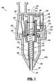
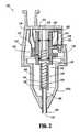
図1および2を参照して、本開示の実施形態体による気腹術ニードルは、一般に、参照番号100として示される。ニードル100は、気腹術ガス「A」(例えば、空気、CO2など)の供給源と、腹腔「C」との間の導管として供され(図5および6を参照のこと)、ここで、この気腹術ガス「A」は、腹腔「C」に侵入し得、かつ膨張し、腹腔鏡下手術の間に内部器官へのそれらとの改良されたアクセスを提供する。以下の開示の実施形態は、主に腹腔鏡下手術に関するが、本明細書に開示される原理を、制限されないで内視鏡手順、関節鏡手順などを含む、多くのその他の外科手順に適用することが想定され、そして本開示の範囲内である。With reference to FIGS. 1 and 2, a pneumoperitoneal needle according to an embodiment of the present disclosure is generally designated as
気腹術ニードル100は、ハンドル、またはその中にチャンバー103を規定するハウジング102、ハウジンング102の遠位端102aに作動可能に接続される細長い中空の管状本体104、および管状本体104内に滑動可能に受容され、管腔107を含む管状ロッド106を含み、管腔107は、管状ロッドを通って延びる。管状本体104は、気腹術腔の裏層を貫通するための形状である遠位端を有する。管状本体106の遠位先端部は、ほぼ平滑であり、そして1つ以上の開口を規定する。気腹術ニードル100は、望ましくは、気腹術ニードルガス投与システムまたは気腹術ガスの供給源(図示せず)と、好ましくは流体係合して、作動可能に接続されている。ハウジング102は、その中に形成された、このガス投与システムとの流体連絡のためのポート130をさらに含む。ポート130は長軸方向に配向されて示されるが、ポート130について、その他の配向が可能であることが想定され、そして本開示の範囲内である。 The
気腹術ニードル100は、ハウジング102のチャンバー103内に作動可能に配置されたバルブアセンブリ140をさらに含む。バルブアセンブリ140は、互いに作動可能に固定された遠位部分144および近位部分146を有するマニホールド142を含む。マニホールド142は、マニホールド142を通る管腔148を規定する内表面171を有する。管状ロッド106は、管状ロッド106の管腔107がマニホールド142の管腔148と流体連絡しているような様式でマニホールド142の遠位部分144に作動可能に接続され、そしてそれから遠位方向に延びている。 The
バルブアセンブリ140は、マニホールド142内に形成され、そして管腔148と流体連絡する第1の通路150を含む。導管152は、第1の通路150を管状本体104のポート130に相互接続する。導管152は、第1の通路150をポート130に流体により接続するために、通路、ホース、チューブなどを備え得る。好ましくは、導管152は、可撓性管材などから製作される。 The
バルブアセンブリ140は、ハウジング102の内表面から遠位方向に延びるステム1700さらに含む。好ましくは、ステム170は、マニホールド142の近位部分146に滑動可能に受容される。遠位シール部材172および近位シール部材174が提供され、そしてステム170を取り囲む。シール部材172、174は、ステム170の外表面と管腔148を規定するマニホールド142の内表面171との間の流体漏れしないシールを生成する。シール部材172、174は、好ましくは、シリコーンを基礎にしたO型シールである。好ましくは、シール部材172、174は、ステム170の外表面に形成される環状の溝176内に着座するか、またはそうでなければ、ステム170もしくはマニホールド170に付着される。このように、シール部材172、174は、マニホールド142が軸方向にそれに沿ってずれるとき、ステム170に対してその場に残る。 The
ステム170は、その外表面とマニホールド142の内表面171との間の環状チャネル180を規定するようなサイズである。シール部材172、174は、環状チャネル180の上端部および下端部に結合する。
バルブアセンブリ140は、その中に指示チャンバー160を規定し、そしてその中に作動可能に配置されたフロート162を有する指示器158を含む。好ましくは、指示器158は、フロート162がオペレーターにより見えるように、透明材料から形成される。
指示器158は、気腹術ニードル100のユーザー/オペレーターに、気腹術ガス「A」が腹腔「C」中に流れているか否かを知らせる。図1および2に示される実施形態では、ステム170は、それを通り、指示チャンバー160の近位領域159と流体連絡しているチャネル178を規定する。従って、以下により詳細に説明されるように、フロート162が、図1に示されるように、指示チャンバー160の遠位領域161中にあるとき、指示器158は、ユーザーに気腹術ガス「A」が腹腔「C」中に流れていることを忠告する。さらに、フロート162が、図2に示されるように、チャンバー160の近位領域159にあるとき、指示器158は、ユーザーに気腹術ニードルガス「A」が腹腔「C」中に流れていないことを忠告する。 The
バルブアセンブリ140は、マニホールド142の近位部分146を通って延び、そして環状チャネル180と連絡している第2の通路154をさらに含む。導管156は、第2の通路154をチャンバー160の遠位領域に流体によって相互接続するために提供される。導管156は、第2の通路154および指示チャンバー160を流体により接続するために通路、ホース、チューブなどを備え得る。 The
ハウジング、バルブアセンブリ、環状本体、環状ロッド、およびその他のパーツは、適切なポリマー材料または金属材料から形成され得る。例えば、ハウジングおよびバルブアセンブリは、ポリカーボネートから形成され得、その一方、管状本体および管状ロッドは、望ましくは、ステンレス鋼である。 The housing, valve assembly, annular body, annular rod, and other parts may be formed from a suitable polymeric or metallic material. For example, the housing and valve assembly may be formed from polycarbonate, while the tubular body and tubular rod are desirably stainless steel.
バルブアセンブリ140は、ステム170とマニホールド142との間に配置される付勢部材182を含む。好ましくは、付勢部材182は、コイルスプリングの形態であるが、しかし、当業者によって企図されるその他のタイプの付勢部材が本明細書に含まれることが理解される。望ましくは、付勢部材182は、図示されるように、ステム170の遠位方向に向く表面と、マニホールド142の遠位部分144との間に取り付けられる。付勢部材182は、図1に見られるように、バルブアセンブリ140のマニホールド142を、最も遠位に、または第1の位置に維持する傾向にある。この位置では、図1に示されるように、遠位シール部材172が第1の通路150の遠位方向に位置決めされる。管状ロッド106もまた、その平滑遠位先端206aが剥き出るか、そして/またはそうでなければ管状本体104から遠位方向に延びるように最も遠位の位置にある。
気腹術ニードル100のバルブアセンブリ140は、最初は、このニードルを通る流体流れが可能である第1の位置にある。第1の通路150は、マニホールド142の管腔148およびステム170のチャネル178に接続される。管腔148は、管状ロッド106の管腔107と連絡する。チャネル178は、指示チャンバー160の領域159と連絡し、フロート162を指示チャンバー160の遠位領域に向かって押す。 The
バルブアセンブリ140は、第1の位置から、図2に示されるように、第1の通路150が遠位シール172の近位方向に配置される第2の位置へと押され得る。この第2の位置では、ニードルを通る流体流れはブロックされる。バルブアセンブリ140は、付勢部材182の付勢を克服すること、および管状ロッド106を管状本体104に対して近位方向にずらすことによって第2の位置に押される。バルブアセンブリ140が第2の位置にあるとき、第1の通路150は、環状チャネル180と流体連絡しており、そして、次いで、第2の通路154と流体連絡している。 The
気腹術ニードル100の使用の間、管状本体104の先端210(図2〜6および8を参照のこと)は、腹腔「C」に挿入されており、そしてそれ故、患者の皮膚に対して押されており、管状ロッド106の遠位先端106aは、管状本体104中に押され、そして、次いで、バルブアセンブリ140は、第1の位置から第2の位置に押される。バルブアセンブリ140が第2の位置にあるとき、ガス投与システムまたは供給源(図示せず)からのガス「A」は、ポート130を通ってハウジング102に入る。次いで、ガス「A」は、導管152を通り、第1の通路150を通り、そしてマニホールド142の環状チャネル180中に流れる。次いで、ガス「A」は、環状チャネル180を通り、そして第2の通路154を出て、導管156を通り、そして指示チャンバー160の遠位領域161中に続き、それによって、フロート162を近位方向に押すか、そして/またはずらす。フロート162の、指示チャンバー160の近位領域内の位置決めは、ユーザーに、ガス「A」が腹腔「C」中に流れていないことを示す。 During use of the
一旦、管状本体104の先端210が患者の腹部壁を完全に貫通し、そして管状ロッド106の遠位先端106aがもはや実質的に妨害されないと、付勢部材182が、バルブアセンブリ140を第2の位置から第1の位置に押す。第1の位置では、ガスは、第1の通路150および管腔148を通り、管状ロッド106の管腔107まで流れ、ガスを腹腔「C」まで供給する。ガスはまた、第1の通路150からチャネル178に流れ、これは、近位領域159と連絡し、フロート162を指示チャンバー160の遠位領域161に位置決めする。この位置では、フロート162は、ユーザーに、ガス「A」が腹腔「C」中に流れていることを示す。 Once the
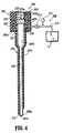
ここで、図3〜8、そして特に図3および4を参照して、本開示の別の実施形態に従う気腹術ニードルは、一般に、参照番号200として示される。 Referring now to FIGS. 3-8, and in particular to FIGS. 3 and 4, a pneumonectomy needle according to another embodiment of the present disclosure is generally designated as
気腹術ニードル200は、ハンドルまたはハウジング202、ハウジング202の前方端部202aに作動可能に接続された細長い中空管状本体204、および管状本体204内に滑動可能に受容された管状ロッド206を含む。気腹術ニードル200は、気腹術ガス投与システム208またはその他のガスの供給源と、好ましくは流体係合して、望ましくは作動可能に接続される。管状本体204は、腹腔の内側裏層を貫通するためにその遠位端204aに形成された穿孔エッジまたは先端210を含む。管状本体204は、以下により詳細に説明されるように、ガス投与システム208との流体連絡のために、その中に形成された半径方向に配向される通路230をさらに含む。通路230は、半径方向に配向されて示されているが、通路230についてその他の配向が可能であることが想定され、そして本開示の範囲内にある。当業者は、通路230が長軸方向に配向され、角度をもって配向され、接線の方向に配向され得るなどであることを容易に理解する。 The
管状ロッド206は、平滑遠位先端206a、ハウジング202中に形成される腔202b中に受容可能な近位端部分206bを含み、そして細長い、それを通って長軸方向に延びる腔207cを規定する。管状ロッド206の遠位先端206aは、その中に形成された開口207aを規定し、これは、この実施形態では、図4〜6に見られるように、遠位方向に向く方向に形成される。しかし、半径方向に配向される方向にある開口を含む、1つ以上の開口が遠位先端206a中に提供され得る。開口207aは、軸方向に配向されて示されているが、開口207aについてその他の配向が可能であることが想定され、そして本開示の範囲内である。当業者は、開口207aが半径方向に配向され、角度をもって配向され、接線方向に配向され得るなどであることを容易に理解する。
好ましくは、図3〜5に見られるように、管状ロッド206は、管状ロッド206が第1または伸長された位置にあるとき、その遠位先端206aが管状本体204の穿孔エッジ210を超えて延びるようなサイズである。管状ロッド206は、その近位端部分206bに形成された半径方向に配向された開口207bをさらに含む。望ましくは、端部プレート220は、近位端部分206bに対して、近位端部分206bを閉鎖し、そして管状ロッド206の端部プレート220と近位端部分206bとの間のガスの通過および/または逃避を阻害するような様式で位置決めされる。あるいは、管状ロッド206は、気腹術ニードル200の長軸に対して実質的に横断方向に配向されている表面(図示せず)によって規定される閉鎖またはシールされた近位端部分206bを有して製造され得ることが想定される。 Preferably, as seen in FIGS. 3-5, the
管状ロッド206は、図6に示されるような第1または伸長された位置から、図5に示されるような第2または引っ込められた位置までの往復長軸方向移動に適合され、そしてコイルスプリング222の影響下で第1または伸長された位置に付勢されている。スプリング222は、ハウジング202の腔202b内に、スプリング222の1つの端部が端部プレート220の近位表面220aと接触し、そしてスプリング222の対向する端部が、ハウジング202の腔202bの内側の遠位方向に配向する表面202cと接触するように配置されている。 The
好ましくは、使用において、管状ロッド206が第1の位置にあるとき、その中に形成された半径方向に配向された開口207bが管状本体204の半径方向に配向された通路230と実質的に整列され、そして/またはそれと実質的に位置決めされるようになる。従って、以下により詳細に説明されるように、管状ロッド206が第1の位置にあるとき、気腹術ガスは、腔207cに入ることが可能となる。さらに、管状ロッド206が第2の位置にあるとき、その中に形成された半径方向に配向された開口207bは、管状本体204の半径方向に配向された通路230との整列から、および/または位置決めから外れている。従って、以下により詳細に説明されるように、管状ロッド206が第2の位置にあるとき、気腹術ガスは、腔207bに入ることを妨げられる。 Preferably, in use, when the
好ましくは、ハウジング202および/または管状ロッド206は、アクリル、ポリスチレン、ポリカーボネートおよびスチレン−アクリロニトリル(SAN)コポリマーのようなポリマー材料から製作され得る。好適な実施形態では、ハウジング202は、単一ユニットとして成型される。管状本体204は、好ましくは、ステンレス鋼またはチタンのような硬い生体適合性材料から製作される。 Preferably, the
図6〜8に最もよく見られるように、気腹術ニードル200は、管状本体204と管状ロッド206との間に配置された、複数のシール、好ましくは、少なくとも一対のシール224、226をさらに含む。シール224、226は、好ましくはOリングタイプのシールまたはガスケットであり、そして、好ましくは、管状ロッド206の周および/または周縁を完全に取り囲む。シール224、226は、好ましくは、例えば、ゴムベースの材料、シリコーンベースの材料などのような弾力性のエラストマー材料から製作される。シール224、226は、管状本体204と管状ロッド206との間のスペースに沿って、かつそれを通るガスの通過を阻害および/またはそうでなければ防ぐタイプである。 As best seen in FIGS. 6-8, the
望ましくは、シール224、226は、管状本体204の内表面に、管状ロッド206が管状本体204に対して軸方向に配置されるとき、シール224、226が管状本体204に対する位置に残り、そして管状ロッド206がそれを横切って滑動することを可能にするような様式で固定される。好ましくは、結合剤、接着剤などを用いて、シール224、226を、管状本体204の内表面に固定して取り付ける。あるいは、管状本体204の内表面には、その中に個々のシール224、226を受容するような形態、および/またはそうでなければそのような寸法の環状溝(図示せず)が提供されることが想定される。このようにして、この環状溝は、シール224、226の管状本体204に対する移動を阻害する。 Desirably, the
好ましくは、以下により詳細に説明されるように、シール224、226の1つは、管状本体204の半径方向に配向された通路230の遠位方向に配置され、その一方、シール224、226のもう1つは、管状本体204の半径方向に配向された通路230の近位方向に配置される。さらに、シール224、226は、管状ロッド206が第1の位置にあるとき、その中に形成された半径方向に配向された開口207bがシール224、226の間に位置決めされ(図5を参照のこと)、そして上記のように、管状本体204の半径方向に配列された通路230と実質的に整列されるように位置決めされる。さらに、シール224、226は、管状本体206が第2の位置にあるとき、その中に形成された半径方向に配向された開口207bが最も近位にあるシール224、226の近位方向に位置決めされるように位置決めされる。第2の位置にある間、最も近位のシール224、226は、管状本体204の半径方向に配向された通路230から、管状ロッド206の半径方向に配向された開口207bを通り、そして管状ロッド206の腔207c中への気腹術ガスの通過を阻害および/またはそうでなければ防ぐ。 Preferably, as will be described in more detail below, one of the
図7に見られるように、Oリングタイプのシール224、226が好ましいけれども、シール224、226は、管状本体204の内側周縁の周りに延びる環状リブ234を含み得、および/またはシール224、226は、管状ロッド206の外側周縁の周りに延びる環状リブ136を含み得、それによって、管状ロッド206と管状本体204との間の間隙距離を減少し、それによってそれらの間の流体の通過を阻害することが想定される。さらに、シリコーンベースの基質238(例えば、グリース、ゲルなど)のような潤滑剤が、管状本体204と管状ロッド206との間に提供され得、それによってそれらの間の流体の流れを阻害することが想定される。 As seen in FIG. 7, although O-ring type seals 224, 226 are preferred, the
あるいは、緊密な許容誤差が、管状本体204と管状ロッド206との間の流体の通過が阻害されるように、管状本体204と管状ロッド206との間に提供され得ることが想定される。 Alternatively, it is envisioned that tight tolerances can be provided between the
ガス投与システム208は、管状本体204を通り、そして腹腔中に流れる注入ガス、例えば、気腹術ガスの量を調節する。ガス投与システム208は、この目的に適する任意の従来システムであり得る。ガス投与システム208は、好ましくは、注入ガス、例えば、気腹術ガスの供給源「A」、気腹術ニードル200にガスの供給源「A」を流体により相互接続する導管212を含み、この注入ガスを、ニードルの目標、および導管212を通るガスの流れを調節するための導管212と作動可能に関連している(例えば、流体連絡する)バルブ214(例えば、ストップコックバルブなど)に運搬する。望ましくは、ガス投与システム208は、腹腔「C」に送達されるガスの容積、量および/または圧力を測定するための、導管212と作動可能に関連(すなわち、流体連絡)するゲージまたは指示器216を含む。 The
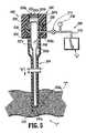
図5および6を特に参照して、気腹術ニードル200を用いる方法をここで説明する。使用において、図5に見られるように、気腹術ニードル200は、患者の腹部領域「T」の表面に対し、管状ロッド206の平滑遠位先端206aが腹部領域「T」の表面に接触するように配置される。遠位先端206aは、最初、腹部領域「T」の表面と係合および/または接触し、矢印「X」によって示されるような遠位方向の力が気腹術ニードル200に付与される。気腹術ニードル200を、矢印「X」の方向に腹部領域「T」の表面に向かって遠位方向に押すか、そして/または進行することは、管状ロッド206を第1の位置から第2の位置に押すことになり、それによって、スプリング222を圧縮し、そして管状本体204の穿孔エッジ210を、腹部領域「T」の表面と接触して配置する。第2の位置にあるとき、腔207cを通り、そして遠位方向に配向された開口207bからの気腹術ガスの流れは、少なくとも実質的には、好ましくは完全に停止される。 With particular reference to FIGS. 5 and 6, a method of using a
継続する遠位方向の力が気腹術ニードル200に付与され、その結果、穿孔エッジ210は、腹部領域「T」の表面を貫通し、そして腹腔「C」に入る。図6に見られるように、一旦、穿孔エッジ210が腹腔「C」に入ると、管状ロッド206は、スプリング222の影響下、その第1の位置まで遠位方向に移動する。この位置では、管状ロッド206の半径方向に配向された開口207bは、管状本体204の半径方向に配向された通路230と、実質的に整列および/または位置決めされる。 A continuing distal force is applied to the
次いで、導管212は、管状本体204の通路230に接続され得、バルブ214が開放され、気腹術ガスが、ガス供給源「A」から出て、導管212を通り、通路230を通り、開口207bを通り、腔207cを通り、管状ロッド206の遠位先端106a中に形成された開口207aを通り、そして腹腔「C」中に(矢印「F」によって示されるように)流れることを可能にする。 The
腹腔「C」は、ゲージ216が特定の所定レベルに到達するまで気腹術ガスが注入される。好ましくは、気腹術ガスは、腹腔「C」を相当程度膨張するために十分な容積および圧力で導入される。一旦、腹腔「C」が、所望および/または十分な量によって膨張されると、バルブ214は、さらなる気腹術ガスが腹腔「C」を再膨張することが必要とされるまで閉鎖されるか、またはそれに代わり、バルブ214が閉められ、それによって気腹術ガスの腹腔「C」中への導入の速度を減少し、そしてそれによって腹腔「C」を均一な膨張条件に維持する。バルブ214は、必要に応じ、手術手順を通じて調節され得、腹腔「C」を注入および/または萎ませることは明瞭である。 The abdominal cavity “C” is infused with pneumoperitoneum gas until the
気腹術ニードル200を、上記で詳細に提示される特定の実施形態に関して記載してきたが、これは、例示によるのみであり、しかも、気腹術ニードル200は、本明細書に開示の実施形態に必ずしも限定されないことが理解されるべきである。なぜなら、代替の実施形態および操作技法が、本開示を考慮すれば、当業者に明らかになるからである。 Although the
従って、改変が、説明された気腹術ニードルの思想から逸脱することなくなされ得ることが予測される。例えば、図4〜6に見られるように、管状ロッド206の近位端部分206bは、遠位先端206aと比較してすそ広がりであることが想定される(すなわち、その遠位部分の直径と比較してより大きな直径を有している)。さらに、管状本体204は、すそ広がりの近位端部分204bを含み得、管状ロッド206のすそ広がりの近位端部分206bを収容する。従って、使用において、管状ロッド206のすそ広がりの近位端部分206bは、管状ロッド206が第1の位置にあるとき、管状本体204のすそ広がりでない遠位端部分204aに対して接し、それによって、管状ロッド206の管状本体204に対する遠位方向の進行を効率的に制限する。その他の実施形態では、管状ロッドおよび/または管状本体は、一定の直径、またはその他の形状を有する。 Accordingly, it is anticipated that modifications can be made without departing from the spirit of the described pneumoperitoneal needle. For example, as seen in FIGS. 4-6, it is envisioned that the proximal end portion 206b of the
管状ロッド206の外表面が、管状本体204の内表面上に提供される相補的部材と係合および/または接合するよう構成および適合された要素または部材を含み得ることがさらに想定され、その結果、管状ロッド206は、長軸の周りに回転すること、それによって、管状ロッド206の開口207bが、管状本体204の通路230との半径方向位置決めから外れて配置されることを阻害および/またはそうでなければ防ぐ。 It is further envisioned that the outer surface of the
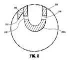
遠位先端206a中に形成される開口207aは、図4に見られるように、望ましくは、遠位方向に配向されるけれども、図8に示されるように、開口207aが、管状ロッド206の遠位先端206a中に形成される少なくとも1つの半径方向に配向された開口240にとって代わり配置され得ることが想定され、そして本開示の範囲内である。管状ロッド206が遠位方向に配向された開口207aおよび少なくとも1つの半径方向に配向された開口240(図示せず)の両方を含み得ることがさらに想定される。開口240が管状ロッド206の長軸に対して所定の角度で配向され得る(図示せず)こともまた想定される。 The
上記の開示は、主に、注入ガス(例えば、気腹術ガス、CO2など)を腹腔に送達するように構成された気腹術ニードルに関するけれども、気腹術ニードルが、制限されずに、生理食塩水、水、水溶液などを含む任意の注入タイプの流体を腹腔に送達し得ることが想定され、そして本開示の範囲内である。Although the above disclosure primarily relates to a pneumotomy needle configured to deliver an insufflation gas (eg, pneumoperitoneum gas, CO2, etc.) to the abdominal cavity, It is envisioned that any infusion type fluid, including saline, water, aqueous solutions, etc., can be delivered to the abdominal cavity and is within the scope of this disclosure.
種々のその他の改変が、本開示の思想から逸脱することなくその範囲内に入ることが想定される。 Various other modifications are envisioned within the scope of the disclosure without departing from the spirit thereof.
(摘要)
身体および/または腹部腔を提供および/または注入するための気腹術ニードルが提供される。この気腹術ニードルは、ハウジング、該ハウジングの遠位表面から延びる細長い管状本体、および該管状本体内に滑動可能に受容される細長い中空管状ロッドを含み得る。好ましくは、この管状本体は、ガス投与システムへの接続のためにそれを通って形成される通路を含む。好ましくは、この管状ロッドは、開口を規定する平滑遠位端、およびそれを通って形成される開口を規定する近位端部分を含む。(Summary)
A pneumoperitoneal needle for providing and / or injecting a body and / or abdominal cavity is provided. The pneumoperitoneal needle may include a housing, an elongated tubular body extending from a distal surface of the housing, and an elongated hollow tubular rod slidably received within the tubular body. Preferably, the tubular body includes a passage formed therethrough for connection to a gas delivery system. Preferably, the tubular rod includes a smooth distal end defining an opening and a proximal end portion defining an opening formed therethrough.
腹腔鏡下手術の前に腹腔を膨張するための腹腔中へのガス状流体の導入が改良された本発明の気腹術ニードルを提供することにより、腹腔中へのガス流れおよび/または通路の表示が提供され、このガス状流体の注入の調節が容易になり、オペレーターが腹腔鏡を操作しやすくなる。 By providing a gastrointestinal needle of the present invention with improved introduction of gaseous fluid into the abdominal cavity for inflating the abdominal cavity prior to laparoscopic surgery, the flow of gas and / or passages into the abdominal cavity is improved. An indication is provided to facilitate adjustment of the injection of this gaseous fluid and facilitate the operator to operate the laparoscope.
Claims (15)
Translated fromJapanese細長い管状本体(104);
該管状本体(104)内に滑動可能に配置される細長い中空の管状ロッド(106)であって、該細長い中空の管状ロッド(106)がガス投与のための遠位開口を備える、細長い中空の管状ロッド(106);
該管状本体(104)および該管状ロッド(106)の近位端にあるバルブアセンブリ(140)であって、マニホールド(142)を含むバルブアセンブリ(140);および
該マニホールド(142)内に取り付けられるステム(170)
を備え、
該マニホールド(142)が、該細長い中空の管状ロッド(106)に作動可能に接続され、該細長い中空の管状ロッド(106)の位置が、該ステム(170)に対する該マニホールド(142)の位置を決定し、該マニホールド(142)および該ステム(170)が、互いに対し、第1の位置で指示チャンバー(160)と連絡する流体経路、および第2の位置で該管状ロッド(106)の内部との流体経路を形成するよう移動可能であり、ガスが該細長い管状本体(104)内に流れていることを示すように該指示チャンバー(160)が適合されている、気腹術ニードル(100)。A care for injectioninto the body cavity pneumoperitoneum needle(100):
An elongated tubular body(104) ;
An elongate hollow tubular rod(106) slidably disposed within the tubular body(104) , the elongate hollow tubular rod(106) comprising a distal opening for gas administration Tubular rod (106) ;
A valve assembly(140) at the proximal end of the tubular body(104) and the tubular rod(106) , comprising a manifold(142) ; and mounted within the manifold(142) Stem(170)
With
The manifold (142) is operably connected to the elongated hollow tubular rod (106), the position of the elongated hollow tubular rod (106) determining the position of the manifold (142) relative to the stem (170). And the manifold(142) and the stem(170) communicate with each other a fluid path in communication with the indicating chamber(160) in a first position and the interior of the tubular rod(106) in a second position. ofRi movable der to form a fluidpath, the gas is elongate tubular body (104) said to indicate that flowing into the instruction chamber (160) is adapted, pneumoperitoneum needle(100 )
前記マニホールド(142)と前記ステム(170)との間に配置される第2のOリング(174)であって、該通路(154)の近位方向に位置決めされる、第2のOリング(174)をさらに含む、請求項1に記載の気腹術ニードル(100)。A first O-ring(172) disposed between the manifold(142) and the stem(170) , positioned distally of a passageway(154) communicating with the indicating chamber(160). A first O-ring(172) ; and a second O-ring(174) disposed between the manifold(142) and the stem(170) , proximal of the passage(154) It is positioned in the direction, further comprising a second O-ring(174), pneumoperitoneum needle according to claim1(100).
注入ガスの供給源;
該注入ガスの供給源を、ポート(130)に、前記マニホールド(142)中の開口(150)と連絡して、流体により相互接続する導管(152);および
該導管(152)を通る注入ガスの流れを調節するために該導管(152)と流体連絡しているバルブを含む、請求項12に記載の気腹術ニードル(100)。The gas dosing system is:
Source of injection gas;
The source of infusion gas, the port(130), in communication with the opening(150) in said manifold(142), a conduit interconnecting the fluid(152); injecting gas through and conductor pipe(152) The pneumoperitoneum needle(100) of claim12 , including a valve in fluid communication with the conduit(152) to regulate flow.
細長い管状本体(104); An elongated tubular body (104);
該管状本体(104)内に滑動可能に配置される細長い中空の管状ロッド(106); An elongated hollow tubular rod (106) slidably disposed within the tubular body (104);
該管状ロッド(106)の近位端に接続された、マニホールド(142)を含むバルブアセンブリ(140);および A valve assembly (140) including a manifold (142) connected to a proximal end of the tubular rod (106); and
該マニホールド(142)内に少なくとも部分的に配置されるステム(170)であって、該マニホールド(142)が、第1の位置と第2の位置との間で、該ステム(170)に対して移動可能である、ステム(170) A stem (170) disposed at least partially within the manifold (142), the manifold (142) between the first position and the second position relative to the stem (170); Movable stem (170)
を備え、With
該マニホールド(142)が第1の位置にあるときに、流体が該管状ロッド(106)と連絡しており、該マニホールド(142)が第2の位置にあるときに、該流体が指示チャンバー(160)と連絡している、 When the manifold (142) is in the first position, fluid is in communication with the tubular rod (106), and when the manifold (142) is in the second position, the fluid is in the indicator chamber ( 160),
気腹術ニードル(100)。Pneumonectomy needle (100).
Applications Claiming Priority (2)
| Application Number | Priority Date | Filing Date | Title |
|---|---|---|---|
| US10/770,980 | 2004-02-03 | ||
| US10/770,980US20050171465A1 (en) | 2004-02-03 | 2004-02-03 | Pneumoperitoneum needle |
Related Child Applications (1)
| Application Number | Title | Priority Date | Filing Date |
|---|---|---|---|
| JP2010229140ADivisionJP2011056270A (en) | 2004-02-03 | 2010-10-08 | Pneumoperitoneum needle |
Publications (2)
| Publication Number | Publication Date |
|---|---|
| JP2005218869A JP2005218869A (en) | 2005-08-18 |
| JP4695890B2true JP4695890B2 (en) | 2011-06-08 |
Family
ID=34679354
Family Applications (2)
| Application Number | Title | Priority Date | Filing Date |
|---|---|---|---|
| JP2005027104AExpired - Fee RelatedJP4695890B2 (en) | 2004-02-03 | 2005-02-02 | Pneumoperitoneum needle |
| JP2010229140AWithdrawnJP2011056270A (en) | 2004-02-03 | 2010-10-08 | Pneumoperitoneum needle |
Family Applications After (1)
| Application Number | Title | Priority Date | Filing Date |
|---|---|---|---|
| JP2010229140AWithdrawnJP2011056270A (en) | 2004-02-03 | 2010-10-08 | Pneumoperitoneum needle |
Country Status (7)
| Country | Link |
|---|---|
| US (4) | US20050171465A1 (en) |
| EP (1) | EP1561428B1 (en) |
| JP (2) | JP4695890B2 (en) |
| AU (1) | AU2005200394B2 (en) |
| CA (1) | CA2495500C (en) |
| DE (1) | DE602005021263D1 (en) |
| ES (1) | ES2345496T3 (en) |
Families Citing this family (21)
| Publication number | Priority date | Publication date | Assignee | Title |
|---|---|---|---|---|
| JP5805827B2 (en)* | 2004-06-29 | 2015-11-10 | アプライド メディカル リソーシーズ コーポレイション | Optical surgical instrument for ventilation |
| US7329233B2 (en)* | 2004-10-05 | 2008-02-12 | Tyco Healthcare Group Lp | Surgical system for laparoscopic surgery |
| US8147453B2 (en)* | 2006-03-13 | 2012-04-03 | Applied Medical Resources Corporation | Balloon trocar |
| US8287503B2 (en) | 2006-03-13 | 2012-10-16 | Applied Medical Resources Corporation | Balloon trocar |
| US8211052B1 (en)* | 2006-07-13 | 2012-07-03 | Lexion Medical Llc | Charged hydrator |
| US8491533B2 (en)* | 2009-10-08 | 2013-07-23 | Ethicon Endo-Surgery, Inc. | Trocar assembly |
| US8932249B2 (en)* | 2009-10-08 | 2015-01-13 | Ethicon Endo-Surgery, Inc. | Trocar assembly |
| US20110112469A1 (en)* | 2009-11-08 | 2011-05-12 | Powerscope Incorporated | Device and process for dispensing multiple-phase mixtures |
| CN101947120B (en)* | 2010-09-30 | 2012-07-04 | 莫易凡 | Spiral puncture outfit with pneumoperitoneum device |
| US20120197078A1 (en) | 2011-01-31 | 2012-08-02 | Eric Stanley | Insufflation needle with integrated image sensor |
| US8888692B1 (en) | 2011-08-26 | 2014-11-18 | Applied Medical Resources Corporation | Trocar cannula assembly and method of manufacture |
| JP5650697B2 (en)* | 2012-09-06 | 2015-01-07 | 富士フイルム株式会社 | Air supply system |
| WO2014134624A1 (en) | 2013-03-01 | 2014-09-04 | The Arizona Board Of Regents On Behalf Of The University Of Arizona | Modified veress needle for tension pneumothorax decompression |
| KR102301914B1 (en) | 2013-03-15 | 2021-09-15 | 어플라이드 메디컬 리소시스 코포레이션 | Trocar cannula assembly with low profile insertion configuration and method of manufacture |
| CN103751866B (en)* | 2014-01-28 | 2016-01-06 | 中国人民解放军第四军医大学 | A kind of medical pneumothorax needle |
| US10799266B2 (en)* | 2015-07-07 | 2020-10-13 | Lexion Medical, Llc | Method and system for gas maintenance to a body cavity using a trocar |
| CN105214150A (en)* | 2015-11-03 | 2016-01-06 | 孟凡美 | A kind of surgery abdominal drainage apparatus |
| CN106344977B (en)* | 2016-10-16 | 2019-03-29 | 陈琴 | Gas-liquid conversion type abdominal cavity suction device |
| US11033665B2 (en) | 2016-11-04 | 2021-06-15 | The Arizona Board Of Regents On Behalf Of The University Of Arizona | Modified veress needle assembly for tension pneumothorax decompression |
| US10806490B2 (en)* | 2017-03-08 | 2020-10-20 | Conmed Corporation | Single lumen gas sealed access port for use during endoscopic surgical procedures |
| GB2624445A (en)* | 2022-11-18 | 2024-05-22 | Cambridge Univ Hospitals Nhs Foundation Trust | A surgical implement |
Family Cites Families (32)
| Publication number | Priority date | Publication date | Assignee | Title |
|---|---|---|---|---|
| FR902521A (en)* | 1944-03-09 | 1945-09-03 | Therapeutic pneumothorax trocar | |
| US2623521A (en)* | 1951-03-12 | 1952-12-30 | Rose Shaw | Indicating stylet needle |
| US4180068A (en)* | 1978-04-13 | 1979-12-25 | Motion Control, Incorporated | Bi-directional flow catheter with retractable trocar/valve structure |
| JPS60238856A (en)* | 1984-05-11 | 1985-11-27 | Toshiba Corp | Accumulator |
| US4808168A (en)* | 1986-05-05 | 1989-02-28 | Endotherapeutics | Pneumoneedle |
| US4808166A (en)* | 1987-10-08 | 1989-02-28 | James Davidov | Anal medication applicator |
| US4869717A (en)* | 1988-04-25 | 1989-09-26 | Adair Edwin Lloyd | Gas insufflation needle with instrument port |
| US5137509A (en)* | 1991-04-17 | 1992-08-11 | Dexide, Inc. | Surgical insufflation instrument |
| US5098388A (en)* | 1991-05-02 | 1992-03-24 | Richard Kulkashi | Veress needle assembly |
| EP0512452B1 (en) | 1991-05-03 | 1996-04-10 | GOLDSTAR CO. Ltd. | Device for mounting a shadow mask in a color television tube |
| US5256148A (en)* | 1991-05-03 | 1993-10-26 | Ethicon, Inc. | Verress needle with enhanced acoustical means |
| US5139485A (en)* | 1991-05-03 | 1992-08-18 | Ethicon, Inc. | Verress needle with enhanced acoustical means |
| US5330432A (en)* | 1991-12-06 | 1994-07-19 | Inbae Yoon | Retractable safety penetrating instrument |
| US5104381A (en)* | 1991-08-30 | 1992-04-14 | Origin Medsystems, Inc. | Pneumoneedle with removable stylet assembly |
| US5665072A (en)* | 1991-11-27 | 1997-09-09 | Yoon; Inbae | Safety needle instrument with movable cannula and needle |
| AU651745B2 (en)* | 1991-12-13 | 1994-07-28 | Covidien Ag | Locking pneumoneedle |
| US5300084A (en)* | 1992-11-23 | 1994-04-05 | United States Surgical Corporation | Pneumoperitoneum needle |
| US5312351A (en)* | 1993-01-29 | 1994-05-17 | Gerrone Carmen J | Combined pneumo-needle and trocar apparatus |
| US5352206A (en)* | 1993-03-31 | 1994-10-04 | Laparomed Corporation | Trocar system having penetration indicator |
| US5437643A (en)* | 1993-05-17 | 1995-08-01 | Ethicon, Inc. | Safety interposer for surgical instruments |
| US5470316A (en)* | 1993-09-07 | 1995-11-28 | United States Surgical Corporation | Body tissue penetrating device having a vacuum indicator |
| US5454791A (en)* | 1993-09-07 | 1995-10-03 | United States Surgical Corporation | Trocar with tissue penetration pressure indicator |
| US5374253A (en)* | 1993-10-12 | 1994-12-20 | Burns, Sr.; Charles N. | Medical instrument with automatic shut-off valve |
| FR2727848A1 (en)* | 1994-12-09 | 1996-06-14 | Yves Zoccola | Trocar for human or animal coelioscopy |
| US5743881A (en)* | 1995-11-03 | 1998-04-28 | Aptec Medical Corporation | Laparoscopic surgical instrument and method of using same |
| JP3715010B2 (en)* | 1995-11-20 | 2005-11-09 | オリンパス株式会社 | Insufflation needle with mantle |
| US6299592B1 (en)* | 1998-03-31 | 2001-10-09 | Northgate Technologies Inc. | Laparoscopic insufflator |
| US6193692B1 (en)* | 1998-08-03 | 2001-02-27 | Bruce C Harris | Verres needle with high flow adaptor |
| US6493692B1 (en)* | 1998-09-30 | 2002-12-10 | Canon Kabushiki Kaisha | Information search apparatus and method, and computer readable memory |
| US20040230160A1 (en)* | 2000-06-22 | 2004-11-18 | Erblan Surgical Inc. | Safety trocar including sealing member |
| US6478775B1 (en)* | 2000-10-02 | 2002-11-12 | Genyx Medical Inc. | Device for delivering non-biodegradable bulking composition to a urological site |
| US7329233B2 (en)* | 2004-10-05 | 2008-02-12 | Tyco Healthcare Group Lp | Surgical system for laparoscopic surgery |
- 2004
- 2004-02-03USUS10/770,980patent/US20050171465A1/ennot_activeAbandoned
- 2005
- 2005-01-31CACA2495500Apatent/CA2495500C/ennot_activeExpired - Fee Related
- 2005-01-31AUAU2005200394Apatent/AU2005200394B2/ennot_activeCeased
- 2005-02-01EPEP05002025Apatent/EP1561428B1/ennot_activeExpired - Lifetime
- 2005-02-01DEDE602005021263Tpatent/DE602005021263D1/ennot_activeExpired - Lifetime
- 2005-02-01ESES05002025Tpatent/ES2345496T3/ennot_activeExpired - Lifetime
- 2005-02-02JPJP2005027104Apatent/JP4695890B2/ennot_activeExpired - Fee Related
- 2006
- 2006-06-26USUS11/475,422patent/US7618399B2/ennot_activeExpired - Lifetime
- 2009
- 2009-11-11USUS12/616,329patent/US7887514B2/ennot_activeExpired - Fee Related
- 2010
- 2010-10-08JPJP2010229140Apatent/JP2011056270A/ennot_activeWithdrawn
- 2011
- 2011-01-20USUS13/009,967patent/US8382716B2/ennot_activeExpired - Fee Related
Also Published As
| Publication number | Publication date |
|---|---|
| CA2495500A1 (en) | 2005-08-03 |
| DE602005021263D1 (en) | 2010-07-01 |
| US20050171465A1 (en) | 2005-08-04 |
| CA2495500C (en) | 2013-07-09 |
| AU2005200394A1 (en) | 2005-08-18 |
| JP2011056270A (en) | 2011-03-24 |
| US20110118658A1 (en) | 2011-05-19 |
| AU2005200394B2 (en) | 2010-07-29 |
| US20100056987A1 (en) | 2010-03-04 |
| US8382716B2 (en) | 2013-02-26 |
| ES2345496T3 (en) | 2010-09-24 |
| US20060282047A1 (en) | 2006-12-14 |
| US7618399B2 (en) | 2009-11-17 |
| EP1561428A3 (en) | 2005-11-02 |
| EP1561428B1 (en) | 2010-05-19 |
| US7887514B2 (en) | 2011-02-15 |
| EP1561428A2 (en) | 2005-08-10 |
| JP2005218869A (en) | 2005-08-18 |
Similar Documents
| Publication | Publication Date | Title |
|---|---|---|
| JP2011056270A (en) | Pneumoperitoneum needle | |
| US11511030B2 (en) | Gastric sizing systems including instruments and methods of bariatric surgery | |
| US12303415B2 (en) | Systems and methods for performing bariatric surgery | |
| AU2014210685B2 (en) | Insufflating surgical access system | |
| US7449011B2 (en) | Apparatus and method for providing percutaneous access and medicament to a target surgical site | |
| US7011314B2 (en) | Floating seal assembly for a trocar | |
| US8608687B2 (en) | Multi-lumen endoscopic accessory and system | |
| JP2009090112A (en) | Surgical portal kit for use in single incision surgery | |
| US20100036323A1 (en) | Flexible cannula with seal | |
| JP4615020B2 (en) | Surgical system for laparoscopic surgery | |
| US12383303B2 (en) | Surgical access device having plural zero closure valves |
Legal Events
| Date | Code | Title | Description |
|---|---|---|---|
| A521 | Request for written amendment filed | Free format text:JAPANESE INTERMEDIATE CODE: A523 Effective date:20050530 | |
| A621 | Written request for application examination | Free format text:JAPANESE INTERMEDIATE CODE: A621 Effective date:20080117 | |
| A131 | Notification of reasons for refusal | Free format text:JAPANESE INTERMEDIATE CODE: A131 Effective date:20100709 | |
| A521 | Request for written amendment filed | Free format text:JAPANESE INTERMEDIATE CODE: A523 Effective date:20101008 | |
| TRDD | Decision of grant or rejection written | ||
| A01 | Written decision to grant a patent or to grant a registration (utility model) | Free format text:JAPANESE INTERMEDIATE CODE: A01 Effective date:20110215 | |
| A01 | Written decision to grant a patent or to grant a registration (utility model) | Free format text:JAPANESE INTERMEDIATE CODE: A01 | |
| A61 | First payment of annual fees (during grant procedure) | Free format text:JAPANESE INTERMEDIATE CODE: A61 Effective date:20110228 | |
| FPAY | Renewal fee payment (event date is renewal date of database) | Free format text:PAYMENT UNTIL: 20140304 Year of fee payment:3 | |
| R150 | Certificate of patent or registration of utility model | Free format text:JAPANESE INTERMEDIATE CODE: R150 | |
| R250 | Receipt of annual fees | Free format text:JAPANESE INTERMEDIATE CODE: R250 | |
| R250 | Receipt of annual fees | Free format text:JAPANESE INTERMEDIATE CODE: R250 | |
| LAPS | Cancellation because of no payment of annual fees |