JP4695665B2 - Rearview mirror with light emitting display - Google Patents
Rearview mirror with light emitting displayDownload PDFInfo
- Publication number
- JP4695665B2 JP4695665B2JP2008090323AJP2008090323AJP4695665B2JP 4695665 B2JP4695665 B2JP 4695665B2JP 2008090323 AJP2008090323 AJP 2008090323AJP 2008090323 AJP2008090323 AJP 2008090323AJP 4695665 B2JP4695665 B2JP 4695665B2
- Authority
- JP
- Japan
- Prior art keywords
- light
- mask member
- mirror
- mirror element
- dark
- Prior art date
- Legal status (The legal status is an assumption and is not a legal conclusion. Google has not performed a legal analysis and makes no representation as to the accuracy of the status listed.)
- Active
Links
Images


Classifications
- B—PERFORMING OPERATIONS; TRANSPORTING
- B60—VEHICLES IN GENERAL
- B60R—VEHICLES, VEHICLE FITTINGS, OR VEHICLE PARTS, NOT OTHERWISE PROVIDED FOR
- B60R1/00—Optical viewing arrangements; Real-time viewing arrangements for drivers or passengers using optical image capturing systems, e.g. cameras or video systems specially adapted for use in or on vehicles
- B60R1/12—Mirror assemblies combined with other articles, e.g. clocks
- G—PHYSICS
- G02—OPTICS
- G02B—OPTICAL ELEMENTS, SYSTEMS OR APPARATUS
- G02B5/00—Optical elements other than lenses
- G02B5/08—Mirrors
- G02B5/0816—Multilayer mirrors, i.e. having two or more reflecting layers
- G02B5/0825—Multilayer mirrors, i.e. having two or more reflecting layers the reflecting layers comprising dielectric materials only
- G02B5/0833—Multilayer mirrors, i.e. having two or more reflecting layers the reflecting layers comprising dielectric materials only comprising inorganic materials only
- G—PHYSICS
- G02—OPTICS
- G02B—OPTICAL ELEMENTS, SYSTEMS OR APPARATUS
- G02B5/00—Optical elements other than lenses
- G02B5/20—Filters
- G02B5/26—Reflecting filters
- B—PERFORMING OPERATIONS; TRANSPORTING
- B60—VEHICLES IN GENERAL
- B60R—VEHICLES, VEHICLE FITTINGS, OR VEHICLE PARTS, NOT OTHERWISE PROVIDED FOR
- B60R1/00—Optical viewing arrangements; Real-time viewing arrangements for drivers or passengers using optical image capturing systems, e.g. cameras or video systems specially adapted for use in or on vehicles
- B60R1/12—Mirror assemblies combined with other articles, e.g. clocks
- B60R2001/1253—Mirror assemblies combined with other articles, e.g. clocks with cameras, video cameras or video screens
Landscapes
- Physics & Mathematics (AREA)
- General Physics & Mathematics (AREA)
- Optics & Photonics (AREA)
- Engineering & Computer Science (AREA)
- Chemical & Material Sciences (AREA)
- Inorganic Chemistry (AREA)
- Multimedia (AREA)
- Mechanical Engineering (AREA)
- Optical Elements Other Than Lenses (AREA)
Description
Translated fromJapaneseこの発明は発光表示装置を組み込んだバックミラーに関し、ミラー素子の背後に暗色マスク部材を配置する場合に光の干渉が発生するのを防止したものである。 The present invention relates to a rearview mirror incorporating a light emitting display device, and prevents light interference from occurring when a dark mask member is disposed behind a mirror element.
発光表示装置を組み込んで情報を表示するようにしたバックミラーとして下記特許文献1〜4に記載されたものがあった。 There exist some which were described in the following patent documents 1-4 as a rearview mirror which incorporated the light emission display apparatus and was made to display information.
特許文献1記載のバックミラーは、ミラー基板の裏面に誘電体多層膜による半透過反射膜を形成し、該半透過反射膜の裏面の全領域のうち一部を除いた領域に有色塗膜を形成し、該半透過反射膜の裏面の前記有色塗膜が形成されていない領域に透明塗膜または半透明塗膜を形成し、ミラー基板の前記透明塗膜または半透明塗膜が形成された領域の裏面側にモニター装置を配置して構成されている。モニター装置がオフのときに有色塗膜とモニター装置の画面とがほぼ同色(黒色)をなすように両者の色彩が設定されている。これによりモニター装置がオフのときに有色塗膜とモニター装置の画面との境界線を不明瞭にして、該境界線によるミラーの視認性の低下を防止している。 In the rearview mirror described in Patent Document 1, a semi-transmissive reflective film made of a dielectric multilayer film is formed on the back surface of a mirror substrate, and a colored coating film is formed on a region excluding a part of the entire region on the back surface of the semi-transmissive reflective film. Formed, a transparent coating film or a semi-transparent coating film was formed in a region where the colored coating film on the back surface of the transflective film was not formed, and the transparent coating film or the semi-transparent coating film of the mirror substrate was formed The monitor device is arranged on the back side of the region. Both colors are set so that the colored coating film and the screen of the monitor device are almost the same color (black) when the monitor device is off. This obfuscates the boundary line between the colored coating film and the screen of the monitor device when the monitor device is off, thereby preventing a reduction in the visibility of the mirror due to the boundary line.
特許文献2記載のバックミラーは、ミラー基板の裏面に誘電体多層膜による半透過反射膜を形成し、該半透過反射膜の裏面側の全領域のうち一部を除いた領域に該半透過反射膜に接して有色板を配置し、該半透過反射膜の裏面側の前記有色板が配置されていない領域にモニター装置を配置して構成されている。モニター装置がオフのときに有色板とモニター装置の画面とがほぼ同色(黒色)をなすように両者の色彩が設定されている。これによりモニター装置がオフのときに有色板とモニター装置の画面との境界線を不明瞭にして、該境界線によるミラーの視認性の低下を防止している。 In the rearview mirror described in
特許文献1記載のバックミラーによれば、半透過反射膜の裏面に塗膜を形成すると半透過反射膜の裏面反射が弱くなる(光の損失が大きい)。そこでバックミラーとして必要な反射率を得るためには半透過反射膜自体の反射率を高くする必要があり、そうすると今度は透過率が低下してモニター装置がオンのときの表示の視認性が低下する。特許文献2記載のバックミラーによれば、半透過反射膜の裏面に塗膜を形成した場合と異なり半透過反射膜の裏面反射が強く得られる(光の損失が少ない)ため、バックミラーとしての性能を満足する反射率とモニター装置がオンのときの表示の視認性を両立させることができる。しかしその反面ミラー基板と有色板との接触が不均一な部分(例えばミラー基板に外力が加わった場合やミラー基板あるいは有色板に歪みが生じていた場合にミラー基板と有色板との接触が不均一になる)で光の干渉が起きやすく、意匠性およびミラーの視認性が悪くなる問題があった。 According to the rearview mirror described in Patent Document 1, when a coating film is formed on the back surface of the transflective film, the back surface reflection of the transflective film becomes weak (the loss of light is large). Therefore, in order to obtain the reflectance required for the rearview mirror, it is necessary to increase the reflectance of the transflective film itself, which in turn reduces the transmittance and decreases the visibility of the display when the monitor device is on. To do. According to the rear-view mirror described in
この発明は上述の点に鑑みてなされたもので、ミラー素子の背後に暗色マスク部材を配置する場合に光の干渉が発生するのを防止した発光表示装置付きバックミラーを提供しようとするものである。 The present invention has been made in view of the above points, and it is an object of the present invention to provide a rearview mirror with a light emitting display device that prevents light interference when a dark color mask member is arranged behind a mirror element. is there.
この発明は透明基板の片面に半透過反射膜を形成したミラー素子と、面内に開口部が形成され、前記ミラー素子の裏面側の、前記開口部に対面する領域を除く全域または前記開口部に対面する領域を除く適宜の領域に対向して配置された少なくとも前面が暗色の暗色マスク部材と、前記ミラー素子と前記暗色マスク部材との間に配置され、該ミラー素子と該暗色マスク部材との間に空隙を形成するスペーサと、前記ミラー素子の背後位置で表示面を前記暗色マスク部材の前記開口部に臨ませて配置された発光表示装置とを具備してなり、前記空隙の距離が、前記ミラー素子の裏面の反射光と、前記ミラー素子を透過した光が前記暗色マスク部材の前面で反射された光とによる光の干渉を生じさせない距離に設定されているものである。この発明によれば透明基板と暗色マスク部材との間にスペーサを配置して該透明基板と該暗色マスク部材との間に、光の干渉を生じさせない距離の空隙を形成したので、光の干渉が発生するのを防止して、意匠性およびミラーの視認性を改善することができる。The present invention relates to a mirror element in which a transflective film is formed on one side of a transparent substrate, an entire area excluding a region facing the opening on the back side of the mirror element, where the opening is formed in the plane, or the opening. At least the front dark dark color mask member is arranged to face the appropriate region excluding the region facing the said is placed between themirror element and the dark color mask member, and saidmirror element and the dark color mask member And a light emitting display device disposed with the display surface facing the opening of the dark color mask member at a position behind the mirror element, and the distance of the gap is The distance betweenthe reflected light on the back surface of the mirror element and thelight that has passed through the mirror element and thelight reflected on the front surface of the dark color mask member is set at a distance that does not cause interference. According to the present invention, since the spacer is disposed between the transparent substrate and the dark color mask member and the gap is formed between the transparent substrate and the dark color mask member so as not to cause the light interference, the light interference is caused. Can be prevented, and the design and the visibility of the mirror can be improved.
前記空隙の距離は例えば0.3mm以上、5mm以下に設定することができる。前記スペーサは例えば、前記暗色マスク部材の前記ミラー素子との対向面の周縁部に突出形成された凸部で構成することができる。あるいは前記スペーサは暗色マスク部材とは別体で構成することもできる。前記ミラー素子と対向する前記暗色マスク部材の表面は平滑であることが望ましく、該表面の算術平均粗さRaを例えば0.6μm以下とすることができる。暗色マスク部材の表面を平滑にすることにより暗色マスク部材の表面での光の散乱を抑制して、意匠性およびミラーの視認性をより良好にすることができる。前記半透過反射膜は例えば誘電体多層膜で構成することができる。前記ミラー素子の可視光域での反射ピーク波長は例えば430nm〜630nm好ましくは500nm〜550nmに設定することができる。 The distance between the gaps can be set to, for example, 0.3 mm or more and 5 mm or less. For example, the spacer may be formed of a convex portion that protrudes from a peripheral portion of the surface of the dark color mask member facing the mirror element. Alternatively, the spacer may be formed separately from the dark mask member. The surface of the dark mask member facing the mirror element is preferably smooth, and the arithmetic average roughness Ra of the surface can be set to 0.6 μm or less, for example. By smoothing the surface of the dark color mask member, scattering of light on the surface of the dark color mask member can be suppressed, and the design and the visibility of the mirror can be improved. The transflective film can be composed of, for example, a dielectric multilayer film. The reflection peak wavelength in the visible light region of the mirror element can be set to, for example, 430 nm to 630 nm, preferably 500 nm to 550 nm.
《実施の形態1》
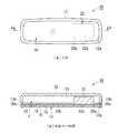
この発明の実施の形態1を説明する。図1はこの発明が適用された車両用インナーミラーの内部構造の概要を示す。(a)は正面図、(b)は(a)のA−A矢視断面図である。インナーミラー10はハウジング12の前面開口部12aにミラー素子14を嵌め込み装着して構成されている。ミラー素子14は透明ガラス、透明光学樹脂等で構成される透明基板16の裏面全体に誘電体多層膜からなる半透過反射膜18を形成した裏面鏡として構成されている。ミラー素子14の裏面側には所定距離dの空隙19を隔てて暗色(例えば黒色)の暗色マスク部材20が対向配置されている。暗色マスク部材20の適宜の領域(図1ではミラー素子14の面内の運転者の視点に近い右隅部)には開口部20aが形成されている。暗色マスク部材20は開口部20aの位置を除いてミラー素子14の裏面全域に対面して配置されている。ハウジング12内の空間13にはミラー素子14の背後位置に発光表示装置22が表示面22aを暗色マスク部材20の開口部20aに臨ませて配置されている。発光表示装置22とミラー素子14とが対面する位置の空隙19の距離はいずれの部分でも暗色マスク部材20とミラー素子14とが対面する位置の空隙19の距離dと同じかまたはそれ以上に設定されている。つまり発光表示装置22は暗色マスク部材20の前面20bよりも前方に突出していない。発光表示装置22は液晶表示装置、EL表示装置等で構成される。発光表示装置22の表示面22aは発光表示装置22がオフのときに暗色マスク部材20の前面20bとほぼ同色(例えば黒色)をなすようにその色彩が設定されている。発光表示装置22は暗色マスク部材20に装着して支持されあるいはハウジング12内の適宜の箇所に装着して支持される。Embodiment 1
Embodiment 1 of the present invention will be described. FIG. 1 shows an outline of the internal structure of a vehicle inner mirror to which the present invention is applied. (A) is a front view, (b) is AA arrow sectional drawing of (a). The
暗色マスク部材20はPP(ポリプロピレン)、PVC(ポリ塩化ビニール)、ASA(アクリルニトリルスチレンアクリルゴム)、PS(ポリスチレン)、ABS(アクリルニトリルブタジエンスチレン)等による暗色の樹脂や少なくとも前面に暗色の塗装をした樹脂のほか、Al、Fe等の金属板に暗色の塗装をしたもの等で構成することができるが、発光表示装置22がオフのときの表示面22aと最も近い色調が得られるものが好ましい。また軽量化の観点からは金属材料よりも樹脂材料の方が好ましい。 The
暗色マスク部材20の構造を図2に示す。(a)は正面図、(b)は(a)のB−B矢視断面図である。暗色マスク部材20は全体が暗色の樹脂板等で一体に構成されている。暗色マスク部材20は正面形状がミラー素子14と同一外形を有し、その前面(ミラー素子14との対向面)20bの周縁部全周にスペーサを構成する凸部20cが一体に形成されている。スペーサ20cは断面が矩形状でありその高さdは形成しようとする空隙19の距離dに等しく設定されている。暗色マスク部材20のスペーサ20cで囲まれた面内には前記開口部20aが形成されている。 The structure of the dark
図1(b)に示すようにハウジング12の開口部12aの内壁面には1本の溝12bが全周にわたり形成されており、ミラー素子14と暗色マスク部材20とは相互に重ね合わせて溝12b内に嵌め込み装着される。このときミラー素子14はその裏面の周縁部全周がスペーサ20cの頂面に当接した状態となる。これによりミラー素子14と暗色マスク部材20とは距離dの空隙19を隔てて対向した状態に保たれる。空隙19の距離dはミラー素子14の裏面の反射光と暗色マスク部材20の表面の反射光との間で光の干渉を生じさせない大きさであり、例えば0.3mm以上が好適である。また空隙19の距離dがあまり大きいとハウジング12の厚みが大きくなってしまうので、該距離dは5mm以下が望ましい。 As shown in FIG. 1B, a
図3は半透過反射膜18の膜構成を模式的に示す。透明基板16は例えばソーダライムガラスで構成される。透明基板16の裏面には半透過反射膜18が成膜されている。半透過反射膜18は透明基板16の裏面に高屈折率材料膜26、低屈折率材料膜28、高屈折率材料膜30の3層を順次積層した誘電体多層膜で構成されている。各層26,28,30は可視光の吸収がないかまたはきわめて吸収が少ない材料で構成されている。高屈折率材料膜26,30は例えばTiO2、Ta2O5、ZrO2、Nb2O5等で構成することができる。低屈折率材料膜28は例えばSiO2、Al2O3、MgF2等で構成することができる。各層26,28,30の光学膜厚はそれぞれλ/4(λ=430nm〜630nm好ましくは500nm〜550nm)であり、ミラー素子14の可視光域での反射ピーク波長は430nm〜630nm好ましくは500nm〜550nmに設定されている。FIG. 3 schematically shows the film configuration of the
高屈折率材料膜26,30をそれぞれTiO2で構成し、低屈折率材料膜28をSiO2で構成した場合の図3のミラー素子14の反射率特性および透過率特性例を図4に示す。この特性は可視光域に単一の反射ピークを持っている。この特性によれば車両用ミラーとして必要な反射率が得られている。また可視域での反射ピーク波長は約530nmであり、その時の反射率は約60%である。したがってコールドミラーのような眩しさを運転者に与えることがない。また反射率が反射ピーク波長の両側でなだらかに減衰しているので、ディスチャージランプの青みの強い短波長域の光とハロゲンランプの赤みがかった長波長域の光の双方の光に対して反射光強度を低減させることができ、より高い防眩効果が得られる。なお半透過反射膜18の高屈折率材料膜をTiO2で構成し、低屈折率材料膜をSiO2で構成する場合は、5層以上積層させると可視域での積分球反射率が高くなりすぎて、夜間後方からのヘッドライト光が運転者に眩しさを感じさせることになる。また層数を増やすにつれて、反射光の分光スペクトル形状が急激な変化をするため、自然な色調にならず鏡に適さなくなり、そのうえ視野角依存性が大きくなって反射光の色調に不連続な箇所が生じるなどの不都合が生じる。したがって半透過反射膜18の積層数は3層または4層が適当である。FIG. 4 shows an example of reflectance characteristics and transmittance characteristics of the
ここでミラー基板の裏面に特許文献1記載のバックミラーのように有色塗膜と透明塗膜または半透明塗膜を形成した場合と図1のバックミラーように暗色マスク部材20を配置した場合(有色塗膜、暗色マスク部材20はいずれも黒色とする)の反射率の違いについて説明する。図5(a)は特許文献1のバックミラーによる光の反射を模式的に示す(図1と共通する部分には同一の符号を用いる)。透明基板16の裏面に半透過反射膜18が形成されている。半透過反射膜18の裏面には発光表示装置22を配置する領域に透明塗膜または半透明塗膜32が形成され、それ以外の領域に黒色の有色塗膜34が形成されている。透明基板16をソーダライムガラスで構成し、半透過反射膜18をTa2O5(高屈折率材料膜)−Al2O3(低屈折率材料膜)−TiO2(高屈折率材料膜)の3層の誘電体多層膜で構成するものとする。このとき積分球反射率は、
・半透過反射膜18の裏面に何も形成しない場合:46%
・半透過反射膜18の裏面に透明塗膜32として透明アクリル塗膜を形成した領域:34%
・半透過反射膜18の裏面に有色塗膜34として黒色アクリル塗膜を形成した領域:31%
であった。すなわち半透過反射膜18の裏面に何も形成しない場合は半透過反射膜18の表面反射のほかその裏面反射がミラー素子全体としての反射率に寄与するのでバックミラーとしての性能を満足する反射率が得られる。これに対し半透過反射膜18の裏面に透明塗膜または半透明塗膜32あるいは有色塗膜34を形成した場合は、半透過反射膜18の表面反射は強く得られミラー素子全体としての反射率に寄与するものの、その裏面反射は弱くなりミラー素子全体としての反射率にほとんど寄与しないためバックミラーとしての性能を満足する反射率が得られない。また有色塗膜34が形成された領域は透明塗膜32が形成された領域に比べて反射率が3%ほど低くなる(誘電体多層膜による反射膜では反射率の低下は顕著である)。このため発光表示装置22がオフのときに、有色塗膜34が形成された領域の反射光と透明塗膜32が形成された領域の反射光とに色調の違い(不自然な濃淡)が現れ、両領域が目視で識別し易く意匠性が悪い。Here, when a colored coating and a transparent coating or a semi-transparent coating are formed on the back surface of the mirror substrate as in the rearview mirror described in Patent Document 1, and when the
When nothing is formed on the back surface of the transflective film 18: 46%
-Area in which a transparent acrylic coating film is formed as the transparent coating film 32 on the back surface of the transflective film 18: 34%
A region where a black acrylic coating film is formed as the
Met. That is, when nothing is formed on the back surface of the
図5(b)は図1のバックミラーによる光の反射を模式的に示す。図5(a)と同様に透明基板16をソーダライムガラスで構成し、半透過反射膜18をTa2O5(高屈折率材料膜)−Al2O3(低屈折率材料膜)−TiO2(高屈折率材料膜)の3層の誘電体多層膜で構成するものとする。このとき積分球反射率は、
・半透過反射膜18の裏面に何も配置しない場合:46%
・半透過反射膜18の裏面に黒色の暗色マスク部材20(表面の算術平均粗さRa=0.6μm以下)を配置した領域:47%
・半透過反射膜18の裏面に発光表示装置22(オフ時の表示面22aの色彩は黒色)を配置した領域:46%
であった。すなわち半透過反射膜18の裏面には空隙19が形成されているので、暗色マスク部材20を配置した領域、発光表示装置22を配置した領域のいずれにおいても、半透過反射膜18の表面反射のほかその裏面反射が強く得られて両反射光ともミラー素子全体としての反射率に寄与するので、バックミラーとしての性能を満足する反射率が得られる。また暗色マスク部材20を配置した領域と発光表示装置22を配置した領域の反射率の差が小さいので、発光表示装置22がオフのときに、暗色マスク部材20を配置した領域の反射光と発光表示装置22を配置した領域の反射光の色調の違いが小さく、両領域が目視で識別し難く意匠性がよい。FIG. 5B schematically shows light reflection by the rearview mirror of FIG. Similarly to FIG. 5A, the
-When nothing is placed on the back surface of the transflective film 18: 46%
Area where black dark mask member 20 (arithmetic surface roughness Ra = 0.6 μm or less) is disposed on the back surface of transflective film 47: 47%
-Area where the light emitting display device 22 (the color of the
Met. That is, since the
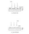
次に暗色マスク部材20の表面粗さが及ぼす影響について説明する。図6は暗色マスク部材20の前面20bが粗い場合と平滑な場合の、該前面20bでの光の反射の違いを示す。(a)は前面20bが粗い場合(表面の算術平均粗さRa=0.6μmより大)である。このとき入射光は前面20bで反射して多くの散乱光を発生させ、反射光は白みを帯びた色調になる。前面20bの粗さが顕著になると、発光表示装置22がオフのときに、表面が粗い暗色マスク部材20を配置した領域と表面が平滑な発光表示装置22を配置した領域とで色調に違いが生じてしまい、両領域が目視で識別しやすくなり意匠性が悪くなる。この散乱光は特に入射光の強度が強い場合には運転者に眩しさや不快感を与えてしまい、安全運転に支障をきたす。これに対し(b)は前面20bが平滑な場合(表面の算術平均粗さRa=0.6μm以下)である。前面20bが平滑な場合は散乱光の発生が抑制されるため、表面が平滑な暗色マスク部材20を配置した領域と表面が平滑な発光表示装置22を配置した領域の色調の違いが小さくなり、両領域が目視で識別し難く意匠性が良好となる。また暗色マスク部材20の表面が粗い場合に比べて散乱光の発生が少ないので運転者に与える眩しさや不快感を軽減することができ、より安全な視界を提供することができる。 Next, the influence of the surface roughness of the dark
各種樹脂材料で暗色マスク部材20の試料を作製して表面の算術平均粗さRaと散乱光の量を測定した結果を次表に示す。なおこの測定では、表面の算術平均粗さRaをキーエンス製レーザー顕微鏡を用いて測定し、散乱光の量は目視にて観察した。
暗色マスク部材の試料(樹脂材料) 表面粗さRa(μm) 散乱光の量
試料1(PP) 0.06 少ない
試料2(塩化ビニール) 0.06 少ない
試料3(ABS+PMMA) 0.07 少ない
試料4(PS) 0.43 少ない
試料5(PS) 0.63 少ない
試料6(PP) 0.8 多い
試料7(PS) 1.27 多い
試料8(PS) 1.73 多い
試料9(PS) 2.69 多い
試料10(PS) 2.92 多い
試料11(PS) 3.32 多い
この測定結果によれば表面の算術平均粗さRaが0.6μm以下(小数点第2桁を四捨五入した値)であれば散乱光が少なく、暗色マスク部材として最適であることがわかる。The following table shows the results obtained by preparing samples of the
Sample of dark mask member (resin material) Surface roughness Ra (μm) Amount of scattered light
Sample 1 (PP) 0.06 Less Sample 2 (vinyl chloride) 0.06 Less Sample 3 (ABS + PMMA) 0.07 Less Sample 4 (PS) 0.43 Less Sample 5 (PS) 0.63 Less Sample 6 (PP ) 0.8 Many Sample 7 (PS) 1.27 Many Sample 8 (PS) 1.73 Many Sample 9 (PS) 2.69 Many Sample 10 (PS) 2.92 Many Sample 11 (PS) 3.32 Many
According to this measurement result, it is understood that if the arithmetic average roughness Ra of the surface is 0.6 μm or less (a value obtained by rounding off the second digit of the decimal point), the scattered light is small and it is optimal as a dark mask member.
次に半透過反射膜18と暗色マスク部材20との間に生じる干渉光について説明する。図7はスペーサ20cが無い場合と有る場合の反射の違いを示す。(a)はスペーサ20cが無い場合である。ミラー素子14に外力が加わり、あるいはミラー素子14や暗色マスク部材20に元々歪みが生じている等の原因により半透過反射膜18と暗色マスク部材20の対向面どうしが不均一に接触すると半透過反射膜18の裏面18aからの反射光と暗色マスク部材20の前面20bからの反射光どうしが干渉して干渉光が発生する。これに対し(b)はスペーサ20cが有る場合である。このとき半透過反射膜18と暗色マスク部材20との間には空隙19が形成されるので半透過反射膜18と暗色マスク部材20とは十分に離れており、半透過反射膜18の裏面18aからの反射光と暗色マスク部材20の前面20bからの反射光どうしは干渉せず、干渉光は発生しない。スペーサ20cの高さdを0.3mm以上に設定すればミラー素子14に外力が加わっても半透過反射膜18と暗色マスク部材20の接触を十分に回避して、干渉光の発生を防止することができる。またスペーサ20cの高さdがあまり高いとハウジング12(図1)の厚みが大きくなってしまうので、スペーサ20cの高さdは5mm以下であることが望ましい。Next, interference light generated between the
《実施の形態2》
前記実施の形態1では暗色マスク部材20の前面20bの周縁部に一体に形成した凸部20cでスペーサを構成したが、暗色マスク部材20と別体の部材でスペーサを構成することもできる。そのように構成した実施の形態を図8に示す。図8は図1のA−A矢視位置に相当する位置で切断した断面図である。図1と共通する部分には同一の符号を用いる。このインナーミラー36はミラー素子14と暗色マスク部材20との間の周縁部全周にスペーサ38を挟み込んで距離dの空隙19を形成している。スペーサ38は環状の暗色(例えば黒色)の樹脂部材等で構成される。<<
In the first embodiment, the spacer is configured by the
前記各実施の形態ではこの発明をインナーミラーに適用した場合について説明したが、アウターミラーその他の車両用バックミラーにも適用することができる。 In each of the embodiments described above, the present invention is applied to the inner mirror. However, the present invention can also be applied to an outer mirror or other vehicle rearview mirror.
10,36…発光表示装置付きバックミラー(インナーミラー)、14,40…ミラー素子、16…透明基板、18…半透過反射膜、19…空隙、20…暗色マスク部材、20a…開口部、20c…スペーサ(凸部)、22…発光表示装置、22a…表示面、38…スペーサ DESCRIPTION OF
Claims (6)
Translated fromJapanese面内に開口部が形成され、前記ミラー素子の裏面側の、前記開口部に対面する領域を除く全域または前記開口部に対面する領域を除く適宜の領域に対向して配置された少なくとも前面が暗色の暗色マスク部材と、
前記ミラー素子と前記暗色マスク部材との間に配置され、該ミラー素子と該暗色マスク部材との間に空隙を形成するスペーサと、
前記ミラー素子の背後位置で表示面を前記暗色マスク部材の前記開口部に臨ませて配置された発光表示装置とを具備してなり、
前記空隙の距離が、前記ミラー素子の裏面の反射光と、前記ミラー素子を透過した光が前記暗色マスク部材の前面で反射された光とによる光の干渉を生じさせない距離に設定されている発光表示装置付きバックミラー。A mirror element having a transflective film formed on one side of a transparent substrate;
An opening is formed in the plane, and at least the front surface disposed opposite to the entire region except the region facing the opening or the appropriate region excluding the region facing the opening on the back side of the mirror element A dark color dark mask member;
Wherein disposed between themirror element and the dark color mask member, and a spacer forming a gap between themirror element and the dark color mask member,
A light-emitting display device disposed with the display surface facing the opening of the dark mask member at a position behind the mirror element,
Light emission in which the distance of the gap is set to a distance that does not cause light interferencebetween the reflected light on the back surface of the mirror element and thelight transmitted through the mirror element reflected on the front surface of the dark mask member Rearview mirror with display device.
Priority Applications (3)
| Application Number | Priority Date | Filing Date | Title |
|---|---|---|---|
| JP2008090323AJP4695665B2 (en) | 2008-03-31 | 2008-03-31 | Rearview mirror with light emitting display |
| US12/362,678US7980711B2 (en) | 2008-03-31 | 2009-01-30 | Light-emitting display device-equipped rear-view mirror |
| EP09001692AEP2106971B1 (en) | 2008-03-31 | 2009-02-06 | Light-emitting display device-equipped rear-view mirror |
Applications Claiming Priority (1)
| Application Number | Priority Date | Filing Date | Title |
|---|---|---|---|
| JP2008090323AJP4695665B2 (en) | 2008-03-31 | 2008-03-31 | Rearview mirror with light emitting display |
Publications (2)
| Publication Number | Publication Date |
|---|---|
| JP2009241733A JP2009241733A (en) | 2009-10-22 |
| JP4695665B2true JP4695665B2 (en) | 2011-06-08 |
Family
ID=40624314
Family Applications (1)
| Application Number | Title | Priority Date | Filing Date |
|---|---|---|---|
| JP2008090323AActiveJP4695665B2 (en) | 2008-03-31 | 2008-03-31 | Rearview mirror with light emitting display |
Country Status (3)
| Country | Link |
|---|---|
| US (1) | US7980711B2 (en) |
| EP (1) | EP2106971B1 (en) |
| JP (1) | JP4695665B2 (en) |
Cited By (2)
| Publication number | Priority date | Publication date | Assignee | Title |
|---|---|---|---|---|
| US10358090B2 (en) | 2014-08-11 | 2019-07-23 | Seiko Epson Corporation | Vehicle imaging device, vehicle imaging display system, and vehicle |
| US10389920B2 (en) | 2014-08-11 | 2019-08-20 | Seiko Epson Corporation | Imaging device, imaging display apparatus, and vehicle |
Families Citing this family (90)
| Publication number | Priority date | Publication date | Assignee | Title |
|---|---|---|---|---|
| US5910854A (en) | 1993-02-26 | 1999-06-08 | Donnelly Corporation | Electrochromic polymeric solid films, manufacturing electrochromic devices using such solid films, and processes for making such solid films and devices |
| US5668663A (en) | 1994-05-05 | 1997-09-16 | Donnelly Corporation | Electrochromic mirrors and devices |
| US6891563B2 (en)* | 1996-05-22 | 2005-05-10 | Donnelly Corporation | Vehicular vision system |
| US6172613B1 (en) | 1998-02-18 | 2001-01-09 | Donnelly Corporation | Rearview mirror assembly incorporating vehicle information display |
| US6326613B1 (en) | 1998-01-07 | 2001-12-04 | Donnelly Corporation | Vehicle interior mirror assembly adapted for containing a rain sensor |
| US6124886A (en) | 1997-08-25 | 2000-09-26 | Donnelly Corporation | Modular rearview mirror assembly |
| US8294975B2 (en) | 1997-08-25 | 2012-10-23 | Donnelly Corporation | Automotive rearview mirror assembly |
| US6445287B1 (en) | 2000-02-28 | 2002-09-03 | Donnelly Corporation | Tire inflation assistance monitoring system |
| US8288711B2 (en) | 1998-01-07 | 2012-10-16 | Donnelly Corporation | Interior rearview mirror system with forwardly-viewing camera and a control |
| US6329925B1 (en) | 1999-11-24 | 2001-12-11 | Donnelly Corporation | Rearview mirror assembly with added feature modular display |
| US6693517B2 (en) | 2000-04-21 | 2004-02-17 | Donnelly Corporation | Vehicle mirror assembly communicating wirelessly with vehicle accessories and occupants |
| US6477464B2 (en) | 2000-03-09 | 2002-11-05 | Donnelly Corporation | Complete mirror-based global-positioning system (GPS) navigation solution |
| US7370983B2 (en) | 2000-03-02 | 2008-05-13 | Donnelly Corporation | Interior mirror assembly with display |
| US7167796B2 (en) | 2000-03-09 | 2007-01-23 | Donnelly Corporation | Vehicle navigation system for use with a telematics system |
| AU2001243285A1 (en) | 2000-03-02 | 2001-09-12 | Donnelly Corporation | Video mirror systems incorporating an accessory module |
| US7581859B2 (en) | 2005-09-14 | 2009-09-01 | Donnelly Corp. | Display device for exterior rearview mirror |
| AU2002251807A1 (en) | 2001-01-23 | 2002-08-19 | Donnelly Corporation | Improved vehicular lighting system for a mirror assembly |
| US7255451B2 (en) | 2002-09-20 | 2007-08-14 | Donnelly Corporation | Electro-optic mirror cell |
| US6918674B2 (en) | 2002-05-03 | 2005-07-19 | Donnelly Corporation | Vehicle rearview mirror system |
| AU2003237424A1 (en) | 2002-06-06 | 2003-12-22 | Donnelly Corporation | Interior rearview mirror system with compass |
| US7329013B2 (en) | 2002-06-06 | 2008-02-12 | Donnelly Corporation | Interior rearview mirror system with compass |
| US7310177B2 (en) | 2002-09-20 | 2007-12-18 | Donnelly Corporation | Electro-optic reflective element assembly |
| WO2004026633A2 (en) | 2002-09-20 | 2004-04-01 | Donnelly Corporation | Mirror reflective element assembly |
| US7446924B2 (en) | 2003-10-02 | 2008-11-04 | Donnelly Corporation | Mirror reflective element assembly including electronic component |
| US7308341B2 (en) | 2003-10-14 | 2007-12-11 | Donnelly Corporation | Vehicle communication system |
| EP1883855B1 (en) | 2005-05-16 | 2011-07-20 | Donnelly Corporation | Vehicle mirror assembly with indicia at reflective element |
| EP1949666B1 (en) | 2005-11-01 | 2013-07-17 | Magna Mirrors of America, Inc. | Interior rearview mirror with display |
| US10690823B2 (en) | 2007-08-12 | 2020-06-23 | Toyota Motor Corporation | Omnidirectional structural color made from metal and dielectric layers |
| US8329247B2 (en) | 2009-02-19 | 2012-12-11 | Toyota Motor Engineering & Manufacturing North America, Inc. | Methods for producing omni-directional multi-layer photonic structures |
| US8593728B2 (en)* | 2009-02-19 | 2013-11-26 | Toyota Motor Engineering & Manufacturing North America, Inc. | Multilayer photonic structures |
| US10048415B2 (en) | 2007-08-12 | 2018-08-14 | Toyota Motor Engineering & Manufacturing North America, Inc. | Non-dichroic omnidirectional structural color |
| US10788608B2 (en) | 2007-08-12 | 2020-09-29 | Toyota Jidosha Kabushiki Kaisha | Non-color shifting multilayer structures |
| US10870740B2 (en) | 2007-08-12 | 2020-12-22 | Toyota Jidosha Kabushiki Kaisha | Non-color shifting multilayer structures and protective coatings thereon |
| US9612369B2 (en) | 2007-08-12 | 2017-04-04 | Toyota Motor Engineering & Manufacturing North America, Inc. | Red omnidirectional structural color made from metal and dielectric layers |
| US8861087B2 (en) | 2007-08-12 | 2014-10-14 | Toyota Motor Corporation | Multi-layer photonic structures having omni-directional reflectivity and coatings incorporating the same |
| US9739917B2 (en) | 2007-08-12 | 2017-08-22 | Toyota Motor Engineering & Manufacturing North America, Inc. | Red omnidirectional structural color made from metal and dielectric layers |
| US8154418B2 (en) | 2008-03-31 | 2012-04-10 | Magna Mirrors Of America, Inc. | Interior rearview mirror system |
| KR101064026B1 (en)* | 2009-02-17 | 2011-09-08 | 엘지이노텍 주식회사 | Light emitting device package and manufacturing method thereof |
| JP4831840B2 (en)* | 2009-02-25 | 2011-12-07 | 株式会社村上開明堂 | Mirror for vehicle and method for manufacturing the same |
| JP2010221899A (en)* | 2009-03-24 | 2010-10-07 | Murakami Corp | Vehicular mirror with monitor |
| US11325533B2 (en) | 2009-04-23 | 2022-05-10 | Magna Mirrors Of America, Inc. | Frameless interior rearview mirror assembly |
| WO2010124064A1 (en) | 2009-04-23 | 2010-10-28 | Magna Mirrors Of America, Inc. | Mirror assembly for vehicle |
| KR20100123433A (en)* | 2009-05-15 | 2010-11-24 | 에스엠알 페턴츠 에스.에이.알.엘. | Inside mirror providing with image display |
| US9346403B2 (en) | 2009-10-07 | 2016-05-24 | Magna Mirrors Of America, Inc. | Rearview mirror assembly |
| US10261648B2 (en) | 2009-10-07 | 2019-04-16 | Magna Mirrors Of America, Inc. | Exterior rearview mirror assembly |
| CN102648113B (en) | 2009-10-07 | 2015-05-27 | 麦格纳镜片美国有限公司 | Frameless interior rearview mirror assembly |
| US11498486B2 (en) | 2009-10-07 | 2022-11-15 | Magna Mirrors Of America, Inc. | Vehicular exterior rearview mirror assembly |
| USD621314S1 (en)* | 2009-11-09 | 2010-08-10 | Williams Roy C | Interior rearview mirror with reverse warning light |
| US9969334B2 (en) | 2010-02-10 | 2018-05-15 | Magna Mirrors Of America, Inc. | Exterior rearview mirror assembly |
| US12115913B2 (en) | 2010-02-10 | 2024-10-15 | Magna Mirrors Of America, Inc. | Vehicular exterior rearview mirror system |
| US9827913B2 (en) | 2010-02-10 | 2017-11-28 | Magna Mirrors Of America, Inc. | Exterior rearview mirror assembly |
| USD633019S1 (en)* | 2010-09-29 | 2011-02-22 | Magna Mirrors Of America, Inc. | Vehicular prismatic mirror assembly |
| USD638761S1 (en) | 2010-09-29 | 2011-05-31 | Magna Mirrors Of America, Inc. | Vehicular electro-optic mirror assembly |
| USD633423S1 (en)* | 2010-09-29 | 2011-03-01 | Magna Mirrors Of America, Inc. | Vehicular electro-optic mirror assembly |
| USD647017S1 (en) | 2010-09-29 | 2011-10-18 | Magna Mirrors Of America, Inc. | Vehicular prismatic mirror assembly |
| US10067265B2 (en)* | 2010-10-12 | 2018-09-04 | Toyota Motor Engineering & Manufacturing North America, Inc. | Semi-transparent reflectors |
| USD660208S1 (en) | 2011-10-14 | 2012-05-22 | Magna Mirrors Of America, Inc. | Vehicular prismatic mirror assembly |
| USD661234S1 (en) | 2011-10-14 | 2012-06-05 | Magna Mirrors Of America, Inc. | Vehicular electro-optic mirror assembly |
| US9215429B2 (en)* | 2011-10-31 | 2015-12-15 | Rosco, Inc. | Mirror monitor using two levels of reflectivity |
| JP6032790B2 (en)* | 2012-03-02 | 2016-11-30 | 現代自動車株式会社Hyundai Motor Company | Vehicle lighting |
| JP2013182833A (en) | 2012-03-02 | 2013-09-12 | Hyundai Motor Co Ltd | Wide light-emitting region lamp for vehicle |
| CA2807615C (en) | 2012-03-08 | 2020-06-30 | Simplehuman, Llc | Vanity mirror |
| US9658375B2 (en) | 2012-08-10 | 2017-05-23 | Toyota Motor Engineering & Manufacturing North America, Inc. | Omnidirectional high chroma red structural color with combination metal absorber and dielectric absorber layers |
| US9664832B2 (en) | 2012-08-10 | 2017-05-30 | Toyota Motor Engineering & Manufacturing North America, Inc. | Omnidirectional high chroma red structural color with combination semiconductor absorber and dielectric absorber layers |
| US9678260B2 (en) | 2012-08-10 | 2017-06-13 | Toyota Motor Engineering & Manufacturing North America, Inc. | Omnidirectional high chroma red structural color with semiconductor absorber layer |
| TWM452096U (en)* | 2012-11-08 | 2013-05-01 | Depo Auto Parts Ind Co Ltd | Rear-view mirror with indicating function |
| EP2947506A4 (en) | 2013-01-16 | 2016-07-13 | Sharp Kk | Mirror display, half mirror plate, and electronic device |
| US9448449B2 (en) | 2013-01-31 | 2016-09-20 | Venkataraman Ramanathan | Glare reduction system |
| IN2013CH01151A (en) | 2013-03-18 | 2015-08-14 | Venkataraman Ramanathan | |
| US9174578B2 (en) | 2013-04-22 | 2015-11-03 | Magna Mirrors Of America, Inc. | Interior rearview mirror assembly |
| US9676336B2 (en) | 2013-06-25 | 2017-06-13 | Magna Mirrors Of America, Inc. | Exterior rearview mirror assembly for vehicle |
| US9487142B2 (en) | 2013-06-25 | 2016-11-08 | Magna Mirrors Of America, Inc. | Rearview mirror assembly for vehicle |
| US10449902B1 (en)* | 2013-09-24 | 2019-10-22 | Rosco, Inc. | Mirror monitor using two levels of reflectivity and transmissibility |
| US10640046B1 (en) | 2013-09-24 | 2020-05-05 | Rosco, Inc. | Convex rearview mirror and monitor with reversible back/socket mount |
| WO2015153043A1 (en) | 2014-04-01 | 2015-10-08 | Toyota Motor Engineering & Manufacturing North America, Inc. | Non-color shifting multilayer structures |
| US9796334B2 (en) | 2014-06-13 | 2017-10-24 | Magna Mirrors Of America, Inc. | Exterior rearview mirror assembly for vehicle |
| US9810824B2 (en) | 2015-01-28 | 2017-11-07 | Toyota Motor Engineering & Manufacturing North America, Inc. | Omnidirectional high chroma red structural colors |
| CA2922596C (en) | 2015-03-06 | 2023-10-24 | Simplehuman, Llc | Vanity mirror |
| US10869537B2 (en) | 2017-03-17 | 2020-12-22 | Simplehuman, Llc | Vanity mirror |
| US11026497B2 (en) | 2018-02-14 | 2021-06-08 | Simplehuman, Llc | Compact mirror |
| US11708031B2 (en) | 2018-03-22 | 2023-07-25 | Simplehuman, Llc | Voice-activated vanity mirror |
| EP3853073A4 (en) | 2018-09-19 | 2022-11-16 | Simplehuman LLC | Vanity mirror |
| JP2020061063A (en)* | 2018-10-12 | 2020-04-16 | 住友化学株式会社 | Optical laminate and manufacturing method therefor |
| US11640042B2 (en) | 2019-03-01 | 2023-05-02 | Simplehuman, Llc | Vanity mirror |
| USD925928S1 (en) | 2019-03-01 | 2021-07-27 | Simplehuman, Llc | Vanity mirror |
| USD927863S1 (en) | 2019-05-02 | 2021-08-17 | Simplehuman, Llc | Vanity mirror cover |
| DE102019111596B4 (en)* | 2019-05-06 | 2022-07-28 | Andreas Fahl Medizintechnik-Vertrieb Gmbh | speaking valve |
| US12246648B2 (en) | 2021-01-19 | 2025-03-11 | Magna Mirrors Of America, Inc. | Vehicular exterior rearview mirror assembly with locking feature |
| US12351108B2 (en) | 2021-07-09 | 2025-07-08 | Magna Mirrors Of America, Inc. | Vehicular exterior rearview mirror assembly with extendable and retractable mirror head |
| US12396577B2 (en) | 2023-03-03 | 2025-08-26 | Simplehuman, Llc | Vanity mirror with hidden sensor |
Family Cites Families (6)
| Publication number | Priority date | Publication date | Assignee | Title |
|---|---|---|---|---|
| US6700692B2 (en)* | 1997-04-02 | 2004-03-02 | Gentex Corporation | Electrochromic rearview mirror assembly incorporating a display/signal light |
| JP4221804B2 (en)* | 1998-09-16 | 2009-02-12 | 市光工業株式会社 | Vehicle mirror with built-in monitoring device |
| JP2000255321A (en)* | 1999-03-09 | 2000-09-19 | Ichikoh Ind Ltd | Mirror for vehicle with built-in monitoring device |
| JP2002067806A (en)* | 2000-08-31 | 2002-03-08 | Ichikoh Ind Ltd | Mirror with vehicle monitor |
| TWI270483B (en)* | 2005-09-06 | 2007-01-11 | Mobiletron Electronics Co Ltd | Lens for rearview mirror |
| JP5178085B2 (en)* | 2007-08-07 | 2013-04-10 | 株式会社村上開明堂 | Rearview mirror with imaging device |
- 2008
- 2008-03-31JPJP2008090323Apatent/JP4695665B2/enactiveActive
- 2009
- 2009-01-30USUS12/362,678patent/US7980711B2/ennot_activeExpired - Fee Related
- 2009-02-06EPEP09001692Apatent/EP2106971B1/ennot_activeExpired - Fee Related
Cited By (2)
| Publication number | Priority date | Publication date | Assignee | Title |
|---|---|---|---|---|
| US10358090B2 (en) | 2014-08-11 | 2019-07-23 | Seiko Epson Corporation | Vehicle imaging device, vehicle imaging display system, and vehicle |
| US10389920B2 (en) | 2014-08-11 | 2019-08-20 | Seiko Epson Corporation | Imaging device, imaging display apparatus, and vehicle |
Also Published As
| Publication number | Publication date |
|---|---|
| US20090244740A1 (en) | 2009-10-01 |
| EP2106971A1 (en) | 2009-10-07 |
| EP2106971B1 (en) | 2012-04-18 |
| JP2009241733A (en) | 2009-10-22 |
| US7980711B2 (en) | 2011-07-19 |
Similar Documents
| Publication | Publication Date | Title |
|---|---|---|
| JP4695665B2 (en) | Rearview mirror with light emitting display | |
| JP5022869B2 (en) | Rearview mirror with light emitting display | |
| JP6725029B2 (en) | Image display transparent member, image display system, and image display method | |
| KR102072350B1 (en) | Head up display system | |
| JP5156319B2 (en) | Rearview mirror for vehicles | |
| EP3187917B1 (en) | Head-up display system | |
| TWI605962B (en) | Rearview mirror and driving auxiliary apparatus | |
| JP7060137B2 (en) | Reflective screen, video display device | |
| TWI270483B (en) | Lens for rearview mirror | |
| JP7056661B2 (en) | Laminated glass for vehicles | |
| JP7209461B2 (en) | Laminated glass for vehicles, image display systems and windshields | |
| WO2017057564A1 (en) | Video projection structure and video projection method | |
| JP2007142780A (en) | Decorative component for vehicle | |
| JP2000255321A (en) | Mirror for vehicle with built-in monitoring device | |
| JP2010221899A (en) | Vehicular mirror with monitor | |
| JP2016097781A (en) | Vehicular windshield | |
| CN112909208B (en) | a display device | |
| US20050141091A1 (en) | Reflex-type screen | |
| JP2005208557A (en) | Reflective screen | |
| CN101971062A (en) | semi-transparent mirror | |
| WO2016104465A1 (en) | Blind spot assist device | |
| JP7598936B2 (en) | Optical structure and head-up display | |
| CN118973977A (en) | Laminated glass | |
| JP2022072753A (en) | Cover member | |
| JP2020134677A (en) | Reflective screen, optical member, image display device |
Legal Events
| Date | Code | Title | Description |
|---|---|---|---|
| A621 | Written request for application examination | Free format text:JAPANESE INTERMEDIATE CODE: A621 Effective date:20100312 | |
| A977 | Report on retrieval | Free format text:JAPANESE INTERMEDIATE CODE: A971007 Effective date:20100610 | |
| A131 | Notification of reasons for refusal | Free format text:JAPANESE INTERMEDIATE CODE: A131 Effective date:20100914 | |
| A521 | Request for written amendment filed | Free format text:JAPANESE INTERMEDIATE CODE: A523 Effective date:20101009 | |
| TRDD | Decision of grant or rejection written | ||
| A01 | Written decision to grant a patent or to grant a registration (utility model) | Free format text:JAPANESE INTERMEDIATE CODE: A01 Effective date:20110208 | |
| A01 | Written decision to grant a patent or to grant a registration (utility model) | Free format text:JAPANESE INTERMEDIATE CODE: A01 | |
| A61 | First payment of annual fees (during grant procedure) | Free format text:JAPANESE INTERMEDIATE CODE: A61 Effective date:20110225 | |
| FPAY | Renewal fee payment (event date is renewal date of database) | Free format text:PAYMENT UNTIL: 20140304 Year of fee payment:3 | |
| R150 | Certificate of patent or registration of utility model | Free format text:JAPANESE INTERMEDIATE CODE: R150 Ref document number:4695665 Country of ref document:JP Free format text:JAPANESE INTERMEDIATE CODE: R150 | |
| FPAY | Renewal fee payment (event date is renewal date of database) | Free format text:PAYMENT UNTIL: 20140304 Year of fee payment:3 | |
| R250 | Receipt of annual fees | Free format text:JAPANESE INTERMEDIATE CODE: R250 | |
| R250 | Receipt of annual fees | Free format text:JAPANESE INTERMEDIATE CODE: R250 | |
| R250 | Receipt of annual fees | Free format text:JAPANESE INTERMEDIATE CODE: R250 | |
| R250 | Receipt of annual fees | Free format text:JAPANESE INTERMEDIATE CODE: R250 | |
| R250 | Receipt of annual fees | Free format text:JAPANESE INTERMEDIATE CODE: R250 | |
| R250 | Receipt of annual fees | Free format text:JAPANESE INTERMEDIATE CODE: R250 | |
| R250 | Receipt of annual fees | Free format text:JAPANESE INTERMEDIATE CODE: R250 | |
| R250 | Receipt of annual fees | Free format text:JAPANESE INTERMEDIATE CODE: R250 | |
| R250 | Receipt of annual fees | Free format text:JAPANESE INTERMEDIATE CODE: R250 | |
| R250 | Receipt of annual fees | Free format text:JAPANESE INTERMEDIATE CODE: R250 | |
| R250 | Receipt of annual fees | Free format text:JAPANESE INTERMEDIATE CODE: R250 | |
| R250 | Receipt of annual fees | Free format text:JAPANESE INTERMEDIATE CODE: R250 |