JP4691249B2 - Rotating feed structure of operation shaft - Google Patents
Rotating feed structure of operation shaftDownload PDFInfo
- Publication number
- JP4691249B2 JP4691249B2JP2000394833AJP2000394833AJP4691249B2JP 4691249 B2JP4691249 B2JP 4691249B2JP 2000394833 AJP2000394833 AJP 2000394833AJP 2000394833 AJP2000394833 AJP 2000394833AJP 4691249 B2JP4691249 B2JP 4691249B2
- Authority
- JP
- Japan
- Prior art keywords
- shaft
- operation lever
- engagement
- lock
- guide
- Prior art date
- Legal status (The legal status is an assumption and is not a legal conclusion. Google has not performed a legal analysis and makes no representation as to the accuracy of the status listed.)
- Expired - Fee Related
Links
Images


Classifications
- B—PERFORMING OPERATIONS; TRANSPORTING
- B60—VEHICLES IN GENERAL
- B60N—SEATS SPECIALLY ADAPTED FOR VEHICLES; VEHICLE PASSENGER ACCOMMODATION NOT OTHERWISE PROVIDED FOR
- B60N2/00—Seats specially adapted for vehicles; Arrangement or mounting of seats in vehicles
- B60N2/02—Seats specially adapted for vehicles; Arrangement or mounting of seats in vehicles the seat or part thereof being movable, e.g. adjustable
- B60N2/04—Seats specially adapted for vehicles; Arrangement or mounting of seats in vehicles the seat or part thereof being movable, e.g. adjustable the whole seat being movable
- B60N2/16—Seats specially adapted for vehicles; Arrangement or mounting of seats in vehicles the seat or part thereof being movable, e.g. adjustable the whole seat being movable height-adjustable
- B60N2/1605—Seats specially adapted for vehicles; Arrangement or mounting of seats in vehicles the seat or part thereof being movable, e.g. adjustable the whole seat being movable height-adjustable characterised by the cinematic
- B60N2/161—Rods
- B60N2/1615—Parallelogram-like structure
- B—PERFORMING OPERATIONS; TRANSPORTING
- B60—VEHICLES IN GENERAL
- B60N—SEATS SPECIALLY ADAPTED FOR VEHICLES; VEHICLE PASSENGER ACCOMMODATION NOT OTHERWISE PROVIDED FOR
- B60N2/00—Seats specially adapted for vehicles; Arrangement or mounting of seats in vehicles
- B60N2/02—Seats specially adapted for vehicles; Arrangement or mounting of seats in vehicles the seat or part thereof being movable, e.g. adjustable
- B60N2/04—Seats specially adapted for vehicles; Arrangement or mounting of seats in vehicles the seat or part thereof being movable, e.g. adjustable the whole seat being movable
- B60N2/16—Seats specially adapted for vehicles; Arrangement or mounting of seats in vehicles the seat or part thereof being movable, e.g. adjustable the whole seat being movable height-adjustable
- B60N2/1635—Seats specially adapted for vehicles; Arrangement or mounting of seats in vehicles the seat or part thereof being movable, e.g. adjustable the whole seat being movable height-adjustable characterised by the drive mechanism
- B60N2/165—Gear wheel driven mechanism
- B—PERFORMING OPERATIONS; TRANSPORTING
- B60—VEHICLES IN GENERAL
- B60N—SEATS SPECIALLY ADAPTED FOR VEHICLES; VEHICLE PASSENGER ACCOMMODATION NOT OTHERWISE PROVIDED FOR
- B60N2/00—Seats specially adapted for vehicles; Arrangement or mounting of seats in vehicles
- B60N2/02—Seats specially adapted for vehicles; Arrangement or mounting of seats in vehicles the seat or part thereof being movable, e.g. adjustable
- B60N2/04—Seats specially adapted for vehicles; Arrangement or mounting of seats in vehicles the seat or part thereof being movable, e.g. adjustable the whole seat being movable
- B60N2/16—Seats specially adapted for vehicles; Arrangement or mounting of seats in vehicles the seat or part thereof being movable, e.g. adjustable the whole seat being movable height-adjustable
- B60N2/1635—Seats specially adapted for vehicles; Arrangement or mounting of seats in vehicles the seat or part thereof being movable, e.g. adjustable the whole seat being movable height-adjustable characterised by the drive mechanism
- B60N2/167—Ratchet mechanism
- B—PERFORMING OPERATIONS; TRANSPORTING
- B60—VEHICLES IN GENERAL
- B60N—SEATS SPECIALLY ADAPTED FOR VEHICLES; VEHICLE PASSENGER ACCOMMODATION NOT OTHERWISE PROVIDED FOR
- B60N2/00—Seats specially adapted for vehicles; Arrangement or mounting of seats in vehicles
- B60N2/02—Seats specially adapted for vehicles; Arrangement or mounting of seats in vehicles the seat or part thereof being movable, e.g. adjustable
- B60N2/04—Seats specially adapted for vehicles; Arrangement or mounting of seats in vehicles the seat or part thereof being movable, e.g. adjustable the whole seat being movable
- B60N2/16—Seats specially adapted for vehicles; Arrangement or mounting of seats in vehicles the seat or part thereof being movable, e.g. adjustable the whole seat being movable height-adjustable
- B60N2/1685—Seats specially adapted for vehicles; Arrangement or mounting of seats in vehicles the seat or part thereof being movable, e.g. adjustable the whole seat being movable height-adjustable characterised by a lock
- B—PERFORMING OPERATIONS; TRANSPORTING
- B60—VEHICLES IN GENERAL
- B60N—SEATS SPECIALLY ADAPTED FOR VEHICLES; VEHICLE PASSENGER ACCOMMODATION NOT OTHERWISE PROVIDED FOR
- B60N2/00—Seats specially adapted for vehicles; Arrangement or mounting of seats in vehicles
- B60N2/90—Details or parts not otherwise provided for
- B60N2/919—Positioning and locking mechanisms
- B60N2/933—Positioning and locking mechanisms rotatable
- B60N2/943—Stepwise movement mechanisms, e.g. ratchets
- Y—GENERAL TAGGING OF NEW TECHNOLOGICAL DEVELOPMENTS; GENERAL TAGGING OF CROSS-SECTIONAL TECHNOLOGIES SPANNING OVER SEVERAL SECTIONS OF THE IPC; TECHNICAL SUBJECTS COVERED BY FORMER USPC CROSS-REFERENCE ART COLLECTIONS [XRACs] AND DIGESTS
- Y10—TECHNICAL SUBJECTS COVERED BY FORMER USPC
- Y10T—TECHNICAL SUBJECTS COVERED BY FORMER US CLASSIFICATION
- Y10T74/00—Machine element or mechanism
- Y10T74/14—Rotary member or shaft indexing, e.g., tool or work turret
Landscapes
- Engineering & Computer Science (AREA)
- Aviation & Aerospace Engineering (AREA)
- Transportation (AREA)
- Mechanical Engineering (AREA)
- Seats For Vehicles (AREA)
- Braking Arrangements (AREA)
- Mechanical Control Devices (AREA)
Description
Translated fromJapanese【0001】
【発明の属する技術分野】
この発明は、操作レバーの往復操作で操作軸を所定の方向に回転させる回転送り構造の改良に関するものであり、例えばシートの着座席の高低を調節するための部材としての適用が好適な回転送り構造に関するものである。
【0002】
【従来の技術】
従来、例えば特開2000−118273号公報に記載されているようなシートボトムの高さ位置を調節する高さ調節機構が知られている。この高さ調節機構は、シートボトムの下部のフレーム間に架設された前後方向一対の架設軸と、各架設軸に直交するように固定された前後方向一対のリンクロッドと、これらリンクロッドの先端側にそれぞれ軸回りに回動可能に軸支された前後方向に延びるシートボトム支持フレームとを備えて構成され、各リンクロッドとシートボトム支持フレームとで形成された四辺形リンク構造にリンク運動を行わせることによって、シートボトムの高さ位置を調節するようになっている。
【0003】
そして、かかる四辺形リンク構造にリンク運動を行わせるために、前方側の架設軸を回動操作する操作レバーがシートボトム下部のフレームに設けられ、この操作レバーを中立位置から下方に向けて往復操作することによる架設軸の一方向への回転で四辺形リンク構造を介してシートボトムが下降する一方、同上方に向けた往復操作でシートバックが上昇するようになされている。
【0004】
そして、操作レバーと架設軸との間には回転送り構造が介設され、この回転送り構造の作用で、操作レバーの下方に向かう往復操作によりシートボトムが下降するとともに、操作レバーの上方に向かう往復操作によりシートボトムが上昇するようになっている。
【0005】
【発明が解決しようとする課題】
ところで、従来の回転送り構造は、上記架設軸を回転させる操作軸と、この操作軸を同心で内装したブレーキドラムと、このブレーキドラムに同心で上記操作軸と共回り可能に装着されたラチェットと、このラチェットと上記操作レバーとの間に介設された連係構造とを備えて構成されているものが通常であった。ブレーキドラムは、架設軸側から操作軸を回そうとしても、ブレーキが機能して回すことができないが、操作レバー側からはブレーキ機能の解除で操作軸を回転させ得るように構成された公知の部材である。
【0006】
また、上記連係構造は、操作レバーの中立位置からの往復操作で往動時にのみラチェットを介して操作軸を回転させるが、復動時にはラチェットを回転させないように構成されている。従って、例えば操作レバーを中立位置から下方に向け往復操作することにより、連係構造およびラチェットを介してこの往復操作が操作軸に伝達され、これによる架設軸の所定方向への回転によってシートボトムが下降する一方、操作レバーの中立位置からの上方に向かう往復操作でシートボトムが上昇することになる。
【0007】
しかしながら、従来のこのような回転送り構造にあっては、操作レバーの復動時(初期位置に戻るとき)に係止プレートがラチェットに干渉した状態で初期位置に戻ろうとするため、「カチカチ」という耳障りな異音が発生するという不具合が存在した。
【0008】
本発明は、上記のような問題点を解消するためになされたものであって、異音の発生がなく、また部品点数を少なくすることができる操作軸の回転送り構造を提供することを目的としている。
【0009】
【課題を解決するための手段】
請求項1記載の発明は、中立位置に位置した操作レバーを一方向に往復操作することにより操作レバーの回動中心と同心で設けられた操作軸を一方向に回転させる一方、操作レバーを他方向に往復操作することにより上記操作軸を他方向に回転させるように構成された操作軸の回転送り構造であって、上記操作軸に外嵌されて操作レバー側からの回動操作による操作軸の回転を許容する一方、操作軸側からの操作軸の回転を阻止するブレーキドラムと、このブレーキドラム外で操作軸に共回り可能に連結され、複数の係合歯を有するロックギヤと、上記操作レバー側に軸支され、複数の係合孔が並設されるとともにロックギヤの回動軸に対して直角となる支持軸回りに回動自在な1個のロックプレートと、操作レバーの往動時に上記ロックギヤの係合歯と上記ロックプレートの係合孔との噛合で操作軸を回転させる一方、操作レバーの復動時に上記噛合を解除する噛合係脱機構とを備えて構成されていることを特徴とするものである。
【0010】
この発明によれば、ロックギヤをブレーキドラムの外側に設けることに伴って、ロックプレートの作動方向を回転軸に対して直角とするとともに、噛合係脱機構によって、操作レバーの復動時にロックギヤとロックプレートの噛合を解除するため、ドラムの外周面に同じ回転方向に形成されたラチェットと係止プレートとの係脱によって操作軸の回転送りを行う従来のものに比較し、復動時のロックプレートの係止を解除するときに異音が生じるような不都合が起こらない。
また、ロックギヤをブレーキドラムの外側に設けたため、ドラムの内周面に形成された内歯ギヤに対する係脱によって操作軸の回転送りを行う従来のものに比較し、ブレーキドラムの径寸法を小さくすることが可能になり、これによって回転送り構造の小型化を実現することができる。
【0011】
請求項2記載の発明は、請求項1記載の発明において、上記ロックプレートは、上記操作レバーに支持軸回りに回動自在に軸支されているとともに、第1付勢手段の付勢力によって上記ロックギヤに係合する係合孔を備え、上記噛合係脱機構は、操作レバーの往動時にロックプレートの係合孔のロックギヤへの係合を許容するとともに、復動時にロックプレートの係合孔のロックギヤへの係合を解除するようにロックプレートを案内するガイド部材を有していることを特徴とするものである。
【0012】
この発明によれば、操作レバーを往動させることにより、第1付勢手段の付勢力で係合孔のロックギヤに対し係合された状態でロックプレートが操作軸回りに回動し、これによるロックプレートの回動で操作軸が所定の方向に回転する一方、操作レバーを復動させることにより、ガイド部材によって係合孔のロックギヤに対する係合が解除されるため、一旦所定の方向に回転した操作軸は、逆回転することなく操作レバーの往動時の回転位置が維持される。
【0013】
従って、操作レバーを中立位置から所定の方向に向けて往復動操作することによるロックプレートの係合孔のロックギヤに対する係脱によって操作軸は所定の方向に間欠的に回転することになる。
【0014】
請求項3記載の発明は、請求項2記載の発明において、上記ロックプレートは、その先端から突出した被案内突起を有し、上記ガイド部材は、操作レバーの中立位置からの往動時に上記被案内突起との干渉で第2付勢手段の付勢力に抗して軸回りに回動し、ロックプレートのロックギヤへ係合した状態における操作軸回りの回動を許容し、所定の位置で係合を解除する第1ガイド部材と、操作レバーの復動時に上記被案内突起との干渉でロックプレートを支持軸回りに回動させて係合孔がロックギヤと係合しないようにする第2ガイド部材とを備えて構成され、上記第2付勢手段は、上記第1付勢手段より大きい付勢力を有していることを特徴とするものである。
【0015】
この発明によれば、操作レバーを所定の方向に向けて往動操作すると、ロックプレートの被案内突起が第2付勢手段の付勢力に抗して第1ガイド部材を軸回りに回動させ、これによる被案内突起の第1ガイド部材に対する摺り抜けでロックプレートが係合した状態のロックギヤが回転するため、操作軸が所定の方向に回転する。そして、操作レバーが最大往動操作された状態では、第2付勢手段の付勢力が第1付勢手段の付勢力より大きいことにより、第1ガイド部材が軸回りに逆方向に回動し、これによる被案内突起を介したロックプレートの支持軸回りの回動で係合孔のロックギヤに対する係合が解除される。ついでこの状態で操作レバーを復動操作すると、被案内突起が第2ガイド部材に案内されてロックプレートのロックギヤに対する係合解除状態が維持されたまま、すなわち操作軸が回転しない状態で操作レバーは元の中立位置に戻ることになる。
【0016】
このように、ガイド部材を、操作レバーの中立位置からの往動時にロックプレートとの連動で操作軸を回転させるように作用する第1ガイド部材と、操作レバーの復動時にもロックプレートとの連動で操作軸を回転させないように作用する第2ガイド部材とを備えて構成することにより、簡単な構造でありながら操作レバーの往復動で操作軸を所定の方向にのみ回転させ得るようにすることができる。
【0017】
請求項4記載の発明は、請求項1乃至3のいずれかに記載の発明において、上記操作レバーは、シートの高さ位置調整用のものであることを特徴とするものである。
【0018】
この発明によれば、シートの高さ位置調整用の機器が簡単な構成でありながら操作が容易なものになる。
【0019】
【発明の実施の形態】
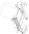
図1は、本発明に係る回転送り構造が適用されたシートの高さ位置調節機構の一実施形態を示す斜視図である。この図に示すように、シート10は、シートボトム11と、このシートボトム11の後部に立設されたシートバック12と、上記シートボトム11およびシートバック12を支持する幅方向一対のサイドフレーム13と、各サイドフレーム13の前後動を案内するスライドレール14とを備えて構成されている。スライドレール14は、フロアに固定されたロアレール14aと、このロアレール14aに上から外嵌された前後動可能なアッパーレール14bとからなっており、上記サイドフレーム13は、このスライドレール14の天板上に固定されている。
【0020】
そして、このようなシート10の一対のサイドフレーム13間にシートボトム11の高さ位置を調節する高さ調節機構20が設けられている。この高さ調節機構20は、一対のサイドフレーム13間に架設された前後方向一対の架設ロッド21と、各サイドフレーム13の内側で架設ロッド21に直交するように固定されて上方に延びる互いに平行な各前後方向一対のリンクロッド22と、これら一対のリンクロッド22間にリンク軸23回りに回動可能に架橋された幅方向一対のシートボトム支持ロッド24と、前方のリンクロッド22の一方側(図1に示す例では左側)から前方に向けて突設されたセクトギヤ25と、このセクトギヤ25に噛合するギヤを備えた、サイドフレーム13に取り付けられる本発明の回転送り構造30とを備えて構成されている。
【0021】
そして、各サイドフレーム13と、これらサイドフレーム13に架設ロッド21を介して連結された各一対のリンクロッド22と、これらリンクロッド22にリンク軸23を介して連結された幅方向一対のシートボトム支持ロッド24とで四辺形リンク構造が形成されている。
【0022】
上記回転送り構造30は、操作レバー70を有しており、この操作レバー70を操作することによる操作軸50の回転で操作軸50と一体回転するギヤに噛合したセクトギヤ25を架設ロッド21回りに共回りさせ、これによる四辺形リンク構造のリンク運動でシートボトム支持ロッド24を昇降させ、シートボトム11の高さ位置を調節するようになっている。
【0023】
図2は、操作軸50の回転送り構造30の一実施形態を示す分解斜視図であり、図3は、その組立て斜視図である。まず、図2および図3に示すように、操作軸50の回転送り構造30は、サイドフレーム13(図1)の外面側に固定されるブレーキドラム40と、このブレーキドラム40に同心で内装された操作軸50と、ブレーキドラム40の底面に同心で積層配置されるロックギヤ60と、中立位置からの上方へ向かう往復操作または下方へ向かう往復操作で操作軸50を一方向または他方向に回転させる操作レバー70と、この操作レバー70と上記ロックギヤ60との間に介設されて操作レバー70とロックギヤ60とを連結するロック部材80と、上記ブレーキドラム40に一体に形成され、かつ、ロック部材80のロックギヤ60に対する係脱を案内する係脱案内部材90とを備えて構成されている。
【0024】
そして、上記ロック部材80と係脱案内部材90とで本発明に係る第1実施形態の噛合係脱機構が形成されている。
【0025】
上記ブレーキドラム40は、外筒41と、この外筒41に嵌め込まれた内筒42と、この内筒42および上記外筒41間に摺接状態で介設されたコイル状のブレーキスプリング43とを備えて構成され、内筒42にこれと共回りする上記操作軸50が同心で配設されたものである(例えば実開平7−19562号公報参照)。
【0026】
かかるブレーキドラム40は、内筒42がロックギヤ60の回転でロックギヤ60側から回されることによりブレーキスプリング43の径寸法が僅かに小さくなって内筒42は周方向に摺動回転するのに対し、操作軸50を回そうとしたときには、ブレーキスプリング43は、径寸法が大きくなって外筒41の内周面を押圧し、これによって操作軸50の軸心回りの回転が阻止されるようになされている。すなわち、操作レバー70側からのロックギヤ60を回転させる操作によって操作軸50を回転させることができるのに対し、操作軸50に直接力を加えても操作軸50は回らないようになっている。
【0027】
また、ブレーキドラム40の外筒41には、開口側の外周面の全周から径方向に外方に向けて突設されたフランジ部44が設けられている。このフランジ部44には、複数個の装着孔44aが穿設され、この装着孔44aに所定のねじが差し通された状態でブレーキドラム40がシート10のサイドフレーム13(図1)にねじ止めされるようになっている。
【0028】
また、内筒42は、外筒41の底板の中心位置に穿設された中心孔を貫通する中心軸45を有している。この中心軸45は、内筒42に一体に固定され、外筒41の底板より外部に突出した部分から先端側に向かってキー軸45a、大径ねじ軸45bおよび小径ねじ軸45cが順次形成されている。キー軸45aは、互いに反対側の周面が切削されて各平行な平面とされた偏平軸によって形成されている。
【0029】
上記ロックギヤ60は、径寸法がブレーキドラム40の外筒41の径寸法と略等しく寸法設定されている。かかるロックギヤ60は、中心位置に上記内筒42のキー軸45aが摺接状態で嵌入される偏平孔61を有しているとともに、外周面には全周に亘って等ピッチで複数の係合歯62が設けられている。そして、偏平孔61が中心軸45のキー軸45aに外嵌された状態でナット46を大径ねじ軸45bに螺着し締結することによってロックギヤ60が中心軸45を介してブレーキドラム40の内筒42に装着された状態になるようにしている。
【0030】
また、上記操作軸50の中心位置には中心孔51が貫設されている一方、上記中心軸45の基端面(内筒42の底板側の面)には、この中心孔51に対向した図略のねじ孔が同心で穿設されている。そして、止め軸52が操作軸50の中心孔51を介して中心軸45のねじ孔に螺着締結されることにより、操作軸50が止め軸52回りに回動可能に内筒42内に装着されるようにしている。
【0031】
上記操作レバー70は、基端側に円形に形成されたロックギヤ60を装着するためのギヤ装着部71と、このギヤ装着部71から径方向に突設された操作桿72とからなっている。ギヤ装着部71には、内径寸法がロックギヤ60の外径寸法より若干大きい装着凹部73が凹設されている。この装着凹部73の底板74には、中心位置に上記小径ねじ軸45cを摺接状態で挿通する中心孔75が穿設され、2枚の皿ばね47を介して上記中心孔75に小径ねじ軸45cを挿通し、ナット53を螺着して締結することにより、ブレーキドラム40およびロックギヤ60が皿ばね47を介して操作レバー70に装着された状態になるようにしている。
【0032】
そして、ブレーキドラム40およびロックギヤ60が操作レバー70に装着された状態で、圧縮弾性変形している皿ばね47の付勢力により、ブレーキドラム40、ロックギヤ60および操作レバー70間のがたつきが有効に防止されるようになっている。
【0033】
また、操作レバー70は、ギヤ装着部71の外周部の適所からブレーキドラム40のフランジ部44に向けて突出したばね受け突片79を有しているとともに、フランジ部44にも上記ばね受け突片79に対応したばね受け突片48が設けられている。これらのばね受け突片48,79は、操作レバー70が中立位置に位置設定された状態で互いに重なり合うように設置位置が設定されている。
【0034】
そして、両ばね受け突片48,79が重なり合った状態で、大径のコイルばねからなるリターンスプリング49がブレーキドラム40の外筒41に外嵌され、このリターンスプリング49の両端部で両ばね受け突片48,79を挟持するようにしている。
【0035】
こうすることによって操作桿72を中立位置からいずれの方向に向けて操作しても、各ばね受け突片48,79が互いに離間する方向に移動するためリターンスプリング49に付勢力が発生し、この付勢力で操作レバー70は中立位置に戻るように力を受けることになる。
【0036】
上記ロック部材80は、ギヤ装着部71と操作桿72との境界位置に装着されるU字形状を呈したU字プレート81と、このU字プレート81の底板の中央部からロックギヤ60の方向に突設されたロックプレート82と、このロックプレート82の先端部から外方に向かって突設された被案内突起83とを備えて構成されている。
【0037】
かかるロック部材80は、U字プレート81が操作桿72の基端側の凹部に嵌め込まれた状態で凹部の図2における上下の内面間に架設される支持軸78がU字プレート81の両側部に貫通され、これによって支持軸78回りに回動自在に軸支された状態になっている。上記支持軸78は、ロックギヤ60の接線方向に延びるように位置設定されている。
【0038】
また、上記ロックプレート82には、図2における左右方向に延びた係合孔84が図2における上下方向に複数個(図2では3つ)並設されている。これらの係合孔84は、上記ロックギヤ60の係合歯62の歯ピッチと同一のピッチ寸法に設定されている。そして、U字プレート81のロックプレート82と反対側の縁部には、ばね受け突片85が突設されている一方、操作桿72内には、ばね受け突片85より前方位置にばね受け軸76が設けられている。
【0039】
また、このばね受け軸76と上記ばね受け突片85との間に第1コイルばね(第1付勢手段)86が張設され、これによってロック部材80を支持軸78回りに図2および図3における反時計方向に付勢している。また、ばね受け突片85は第1コイルばね86により付勢された状態で、図2に示すように、その先端部がギヤ装着部71と操作桿72との間に形成された隔壁77に当止し、これ以上の支持軸78回りの回動が阻止された係合位置に位置設定されるようになっている。
【0040】
そして、ロック部材80が係合位置に位置設定された状態では、図3に示すように、ロックプレート82の各係合孔84がロックギヤ60の係合歯62に嵌まり込んで係合した状態になっている。従って、この状態で操作桿72を把持して上下のいずれかの方向に操作すると、この操作は、ロック部材80、ロックギヤ60を介してブレーキドラム40の内筒42に伝達され、ロックギヤ60側からの回転力の伝達によっては回転するように構成された内筒42が回転することにより、これに誘導されて操作軸50が操作桿72の操作方向と同一方向に回転することになる。
【0041】
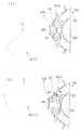
以下、係脱案内部材90について、図4および図5を基に詳細に説明する。図4は、係脱案内部材90を示す図3のA線矢視の部分拡大図であり、図5は、ガイドプレート91を示す図4のB線視図である。これらの図に示すように、係脱案内部材90は、上記ロック部材80に対向してブレーキドラム40のフランジ部44から延設された一対のガイドプレート(第1ガイド部材)91と、これら各ガイドプレート91との協働でロック部材80の被案内突起83をガイドするガイドカム(第2ガイド部材)92とを備えて構成されている。
【0042】
ガイドプレート91は、ブレーキドラム40のフランジ部44からロックギヤ60の方向に直角に折り曲げられて形成した一対の折曲げ片91aと、各折曲げ片91aの先端側から互いに対向する方向に延設された延設片91bと、各延設片91bの先端部が二股状に分けられて形成した一方側である第1ガイド片91cと、同他方側である軸受片91dとからなっている。
【0043】
上記各第1ガイド片91cは、その上面でロック部材80の被案内突起83をガイドするものであり、それぞれの延設片91bからロック部材80の方向に突出した状態で互いに対向方向に延ばされている。各第1ガイド片91cの先端間には、被案内突起83が通過し得るように寸法設定された隙間93が形成されている。
【0044】
また、各軸受片91dは、ガイドカム92を軸支するためのものであり、第1ガイド片91cと反対側の延設片91bの縁部がブレーキドラム40の外筒41の方向に折り曲げられた上で互いに対向する方向に延設されて形成している。
【0045】
上記ガイドカム92は、各ガイドプレート91の軸受片91dのカム軸94回りに回動自在に軸支された円柱片92aと、各円柱片92aから第1ガイド片91cの反対方向に延設された略三角形状の三角片92bと、各三角片92bの先端縁部に一体に形成された第2ガイド片92c、各円柱片92aから三角片92bと反対方向に突設されたばね支持片92fとを備えて構成されている。各ばね支持片92f間には、第2コイルばね(第2付勢手段)95が張設され、この第2コイルばね95の付勢力によって各ガイドカム92は、それぞれのカム軸94回り互いに反対方向に向かう力を受けている。
【0046】
上記各円柱片92aは、ガイドプレート91より外筒41寄りの位置で、かつ、第1ガイド片91cと軸受片91dの外縁部との間に位置するように厚み寸法が設定されている。また、上記各三角片92bは、円柱片92aのフランジ部44寄りの縁部から延設されている。さらに、上記第2ガイド片92cは、この三角片92bの先端(図5の下端)縁部から第1ガイド片91cに対向するように突出している。
【0047】
かかる第2ガイド片92cは、ガイドカム92が上記第2コイルばね95の付勢力を受けた状態で、表面側が第1ガイド片91cと面一になる面一ガイド片92dと、この面一ガイド片92dに続く円弧状を呈した円弧ガイド片92eとからなっている。各円弧ガイド片92eは、内面側が円柱片92aに対向しているとともに、それぞれの先端部は被案内突起83よりも外筒41寄りの位置で互いに対向している。
【0048】
そして、第2コイルばね95は、その付勢力が上記第1コイルばね86の付勢力より大きくなるように設定されている。因みにここでいう各コイルばね95,86の付勢力は、モーメントを考慮した付勢力である。
【0049】
従って、操作レバー70が中立位置に位置設定された状態、すなわち、図5に示すように、ロック部材80の被案内突起83が各ガイドカム92間の隙間93に位置した状態で操作桿72をいずれかの方向に往動操作すると、まず、被案内突起83が円弧ガイド片92eの内面側を外筒41の方向に押圧するため、ガイドカム92はカム軸94回りに第1ガイド片91cから離間する方向に回動し、これによって被案内突起83は第1ガイド片91cと円弧ガイド片92eとの間を摺り抜けて面一ガイド片92d上に位置した状態になる。
【0050】
そしてこの状態では、第2コイルばね95の付勢力の方が第1コイルばね86の付勢力より大きいため、第2コイルばね95の付勢力によってガイドカム92はカム軸94回りに回動し、被案内突起83を押し上げてロックプレート82を係合解除位置に位置設定するとともに、面一ガイド片92dは第1ガイド片91cと面一になる。
【0051】
この状態で操作桿72を復動操作することにより、被案内突起83は、第1ガイド片91cの表面側に案内されてガイドカム92間の隙間93に向かい、そこに到達した時点で第1コイルばね86の付勢力によるロック部材80の支持軸78回りの回動で元の係合位置に戻ることになる。
【0052】
以下第1本実施形態の回転送り構造30の作用について、図6および図7を基に、必要に応じて図2〜図5を参照しながら説明する。図6および図7は、回転送り構造30の作用を説明するための説明図であり、図6の(イ)は、操作レバー70が中立位置にある状態、図6の(ロ)は、操作レバー70を上方に向けて往動させつつある状態、図7の(イ)は、操作レバー70を最往動位置にまで往動させた状態、図7の(ロ)は、操作レバー70を復動させつつある状態をそれぞれ示している。
【0053】
まず、図6の(イ)に示す、操作レバー70が中立位置に位置設定された状態では、ロック部材80は、第1コイルばね86により支持軸78回りにロックギヤ60に向かう付勢力を受け、これによってロックプレート82の係合孔84がロックギヤ60の係合歯62に外嵌してロックギヤ60が回り止めされている。また、上下一対のガイドカム92は、第2コイルばね95によって互いに反対方向に付勢され、これによってガイドカム92の面一ガイド片92dの表面側はガイドプレート91の第1ガイド片91cと面一状態になっている。このとき、ロック部材80の被案内突起83は、上下のガイドカム92間の隙間93に位置している。
【0054】
この状態で操作桿72を把持して上方に往動操作することにより、被案内突起83がガイドカム92の円弧ガイド片92eの内面側に案内されつつ上方に移動する。この移動に伴ってロックギヤ60は中心軸45(図2)回りに反時計方向に回転する。この回転は、ブレーキドラム40を介して操作軸50の軸心回りの回転に伝達される。そして、被案内突起83が円弧ガイド片92eの先端部に到達すると第1ガイド片91cと干渉することによりこれに押されてガイドカム92がカム軸94回りに時計方向に回動し、これによって被案内突起83は、図6の(ロ)に示すように、円弧ガイド片92eと第1ガイド片91cとの間を摺り抜けることになる。
【0055】
そして、操作桿72が最往動位置まで引き上げられると、被案内突起83は、図7の(イ)に示すように、第1ガイド片91cを遣り過ごして第2ガイド片92cの面一ガイド片92dにのみ当接した状態になるが、この状態では、第2コイルばね95の付勢力の方が第1コイルばね86の付勢力より大きく設定されているため、ガイドプレート91はカム軸94回りに時計方向に回動し、面一ガイド片92dが被案内突起83を図6の左方に向けて押圧する。これによってロック部材80は支持軸78回りに回動してロックプレート82の係合孔84がロックギヤ60の係合歯62から外れた状態になる。
【0056】
ついで、操作桿72を復動操作すると、係合歯62が、図7の(ロ)に示すように、第1ガイド片91cに案内されて移動するため、ロックプレート82の係合孔84がロックギヤ60の係合歯62から外れた状態が維持される。従って、操作桿72の復動操作によってはロックギヤ60が回転することはない。
【0057】
そして、操作桿72が中立位置に戻ると、被案内突起83が第1ガイド片91cから外れるため、第1コイルばね86の付勢力によってロック部材80が支持軸78回りに回動し、これによってロックプレート82の係合孔84がロックギヤ60の係合歯62に再度外嵌し、図6の(イ)に示す状態に戻る。
【0058】
従って、操作桿72の上方に向かう往復操作を繰り返すことにより、ロックギヤ60は中心軸45(図2)回りに時計方向に回転し、この回転で操作軸50、セクトギヤ25(図1)、リンクロッド22およびシートボトム支持ロッド24を介してシートボトム11が昇降させられることになる。また、操作レバー70を中立位置から下方に向けて往復操作することにより、上記と同様の作用でロックギヤ60を中心軸45回りに反時計方向に回転させることができる。
【0059】
上記の第1実施形態の噛合係脱機構が適用された回転送り構造30は、以上詳述したように、中立位置に設定された操作レバー70を一方向に往復操作することにより操作レバー70の回動中心と同心で設けられた操作軸50を一方向に回転させる一方、操作レバー70を他方向に往復操作することにより操作軸50を他方向に回転させるように構成した操作軸の回転送り構造であり、操作軸50に外嵌されて操作レバー70側からの回動操作による操作軸50の回転を許容する一方、操作軸50側からの操作軸50の回転を阻止するブレーキドラム40と、このブレーキドラム40外で操作軸50に共回り可能に連結されるロックギヤ60と、操作レバー70の往動時にロックギヤ60との噛合で操作軸50を回転させる一方、操作レバー70の復動時に噛合を解除する噛合係脱機構とを備えて構成している。
【0060】
そして、まず第1に、ロックギヤ60をブレーキドラム40の外側に設けたため、ドラムの内周面に形成された内歯ギヤに対する係脱によって操作軸50の回転送りを行う従来のものに比較し、ブレーキドラム40の径寸法を小さくすることが可能になり、これによって回転送り構造の小型化を実現することができる。
【0061】
また、上記噛合係脱機構を、操作レバー70に支持軸回りに回動自在に軸支され、かつ、第1コイルばね86の付勢力によってロックギヤ60に係合する係合孔84を備えたロックプレート82と、操作レバー70の往動時にロックプレート82の係合孔84のロックギヤ60への係合を許容するとともに、復動時にロックプレート82の係合孔84のロックギヤ60への係合を解除するようにロックプレート82を案内する係脱案内部材90とから構成したため、操作レバー70を往動させることにより、第1コイルばね86の付勢力で係合孔84のロックギヤ60に対する係合が係脱案内部材90によって確保された状態になってロックプレート82が操作軸50回りに回動し、このロックプレート82の回動で操作軸50が所定の方向に回転する一方、操作レバー70を復動させることにより、係脱案内部材90によって係合孔84のロックギヤ60に対する係合が解除され、これによって一旦所定の方向に回転した操作軸50は、逆回転することなく操作レバー70の往動時の回転位置を維持することができる。
【0062】
従って、操作レバー70を中立位置から所定の方向に向けて往復動操作することによるロックプレート82の係合孔84のロックギヤ60に対する係脱によって操作軸50を所定の方向に間欠的に回転させることができる。
【0063】
また、ロックプレート82には先端から突出した被案内突起83を設けるとともに、係脱案内部材90を、操作レバー70の中立位置からの往動時に被案内突起83との干渉で第2コイルばね95の付勢力に抗してカム軸94回りに回動し、ロックプレート82のロックギヤ60への係合を確保した状態における操作軸50回りの回動を許容するガイドカム92と、操作レバー70の復動時に被案内突起83との干渉でロックプレート82を支持軸回りに回動させて係合孔84のロックギヤ60に対する係合を解除させるガイドプレート91とを備えて構成したため、操作レバー70を所定の方向に向けて往動操作すると、ロックプレート82の被案内突起83が第2コイルばね95の付勢力に抗してガイドカム92を軸回りに回動させ、これによる被案内突起83のガイドカム92に対する摺り抜けでロックプレート82が係合した状態のロックギヤ60が回転するため、操作軸50が所定の方向に回転する。
【0064】
そして、操作レバー70が最大往動操作された状態では、第2コイルばね95の付勢力が第1コイルばね86の付勢力より大きく設定されていることにより、ガイドカム92が軸回りに逆方向に回動し、これによる被案内突起83を介したロックプレート82の支持軸回りの回動で係合孔84のロックギヤ60に対する係合が解除される。ついでこの状態で操作レバー70を復動操作すると、被案内突起83がガイドプレート91に案内されてロックプレート82のロックギヤ60に対する係合解除状態が維持されたまま、すなわち操作軸50が回転しない状態で操作レバー70は元の中立位置に戻ることになる。
【0065】
このように、係脱案内部材90を、操作レバー70の中立位置からの往動時にロックプレート82との連動で操作軸50を回転させるように作用するガイドカム92と、操作レバー70の復動時にもロックプレート82との連動で操作軸50を回転させないように作用するガイドプレート91とを備えて構成することにより、簡単な構造でありながら操作レバー70の往復動で操作軸50を所定の方向にのみ回転させ得るようにすることができる。
【0066】
図8は、本発明に係る噛合係脱機構の第2実施形態を示す図であり、(イ)は、ガイドカム92′およびロック部材80を示す斜視図、(ロ)は、(イ)のガイドカム92′のC線視図である。図8に示すように、第2実施形態の噛合係脱機構は、第1実施形態と同様に構成されたロック部材80と、ガイドカム92′とを備えて構成され、第1実施形態で採用されていたガイドプレート91は採用されない。すなわち、本発明に係る係脱案内部材90がガイドカム92′のみによって形成されている。
【0067】
ガイドカム92′は、第1実施形態と同様にブレーキドラム40のフランジ部44に設けられたカム軸94回りに回動自在に軸支される一対の円柱片92aと、第1実施形態と同様に円柱片92aから突設されたばね支持片92fと、このばね支持片92fと反対側の円柱片92aの位置に一体に設けられた第3ガイド片92gとを備えて構成されている。
【0068】
上記第3ガイド片92gは、操作レバー70(図1)が中立位置に位置設定された状態でロック部材80を支持する支持軸78と平行で、かつ、操作レバー70が往動操作されてもロックプレート82の被案内突起83と干渉しない平行面92hを有する非干渉片92iと、この非干渉片92iと直交し、かつ、操作レバー70が往動操作されたときに上記被案内突起83と干渉する直交面92jを有する干渉片92kとを備えて構成されている。
【0069】
上記干渉片92kは、その直交面92jの長さ寸法が操作レバー70の略80%の回動範囲で被案内突起83と当接するように寸法設定されているとともに、この直交面92jと略直交してばね支持片92fと反対方向に延びる第2平行面92mを有している。第2平行面92mは、操作レバー70が往動操作され終わった状態でも、被案内突起83がこの第2平行面92mから外れない長さ寸法に設定されている。
【0070】
第2実施形態の噛合係脱機構によれば、操作レバー70が中立位置に設定されている状態では、被案内突起83は、図8の(ロ)に示すように、一対の第3ガイド片92g間に位置しているとともに、図8の(イ)に示すように、ロックプレート82の係合孔84がロックギヤ60の係合歯62に係合している。従って、この状態で操作レバー70を図8の上方に向けて往動操作すると、被案内突起83が直交面92jに当接するまでは、第3ガイド片92gがカム軸94回りに回動することなく操作レバー70と共回りするロック部材80の中心軸45回りの回転によるロックプレート82の回動によってロックギヤ60が回転し、操作軸50が一方向に回転することになる。
【0071】
そして、操作レバー70の上方に向けた往動操作を継続することにより、被案内突起83が直交面92jを押圧し、これによって図8の(ロ)の上方側の第3ガイド片92gは、カム軸94回りに時計方向に回動し、図8の(ロ)の矢印Xで示す状態になる。
【0072】
そして、さらに操作レバー70を往動操作することにより、被案内突起83は、直交面92jの先端側から干渉片92kの第2平行面92mに移行し、図8の(ロ)の矢印Yで示す状態になる。この状態になると、第1コイルばね86(図4)の付勢力より大きく設定されている第2コイルばね95の付勢力によって第3ガイド片92gがカム軸94回りに反時計方向に回動し、これによるロック部材80の支持軸78回りの回動によってロックプレート82のロックギヤ60に対する係合が解除され、操作レバー70の操作がロックギヤ60を介して操作軸50に及ばなくなる。
【0073】
この状態で操作レバー70を、図8の(ロ)における下方に向けて復動操作することにより、被案内突起83は第2平行面92mを摺動しながら図8の(ロ)の下方に移動し、第2平行面92mを外れることにより、図8の(ロ)に実線で示した元の位置に戻ることになる。従って、かかる上方に向けた操作レバー70の往復動操作を繰り返すことにより、操作軸50は一方向に回転する一方、操作レバー70を下方に向けて往復操作することにより、操作軸50は他方向に向けて回転することになる。
【0074】
そして、第2実施形態の噛合係脱機構によれば、ガイドプレート91を設ける必要がないため、その分部品コストの軽減化に貢献することができる。
【0075】
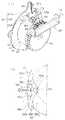
図9は、本発明に係る噛合係脱機構の第3実施形態を示す図であり、(イ)は、ガイドカム92″およびロック部材80を示す斜視図、(ロ)は、(イ)のガイドカム92″のD線視図である。図9に示すように、第3実施形態の噛合係脱機構は、第1実施形態と同様に構成されたロック部材80と、第3実施形態固有のガイドカム92″とを備えて構成されている。第3実施形態においては、第1実施形態で採用されていたガイドプレート91は採用されていないばかりか、ガイドカム92″は1つのみが採用されている。その他の構成は、第2実施形態のものと同様である。すなわち、第3実施形態においても、係脱案内部材90は、ガイドカム92″のみから形成されている。
【0076】
すなわち、第3実施形態のガイドカム92″は、図9の(イ)に示すように、第2実施形態において線対称に形成された一対のガイドカム92′を円柱片92a1つで共用されるように合体させた形状を備えている。すなわち、かかるガイドカム92″は、上記円柱片92aに対応した、正面視で半円状の1つの半円柱片92a′と、この半円柱片92a′から図9の(イ)の上下方向に延びた一対の干渉片92kと、これら干渉片92kの対向面間の隙間を、被案内突起83と反対側で覆う覆い片92nとからなっている。半円柱片92a′は、フランジ部44に設けられたカム軸94回りに回動自在に軸支されている。
【0077】
上記半円柱片92a′は、ブレーキドラム40のフランジ部44に被案内突起83に対応して設けられた1つのカム軸94によって当該カム軸94回りに正逆回動自在に軸支されている。そして、一対の干渉片92k間の隙間部分に位置する半円柱片92a′の弦に当る部分の外面で、第2実施形態における平行面92hに相当した、上記中心軸45を中心とする円弧面92pが形成されている。この円弧面92pは、ロックプレート82が係合位置に設定された状態の被案内突起83が当接されるとともに、操作レバー70の略80%の往動によっては被案内突起83が干渉片92kの直交面92jに到達しないように寸法設定されている。
【0078】
また、覆い片92nの頂部(図9の左方)には、第2コイルばね95が、カム軸94の軸心と上記頂部とを結ぶ直線上で張設され、この第2コイルばね95の付勢力でガイドカム92″は、被案内突起83が円弧面92pの中央部に位置する中立姿勢を維持するようになっている。
【0079】
第3実施形態のガイドカム92″によれば、操作レバー70が中立位置に設定されている状態では、被案内突起83は、図9の(ロ)に示すように、半円柱片92a′の円弧面92pの中央部に位置しているとともに、図9の(イ)に示すように、ロックプレート82の係合孔84がロックギヤ60の係合歯62に係合している。従って、この状態で操作レバー70を、例えば図9の上方に向けて往動操作すると、被案内突起83が干渉片92kの直交面92jに当接するまでは、ガイドカム92″がカム軸94回りに回動することなく操作レバー70と共回りするロック部材80の中心軸45回りの回転によるロックプレート82の回動によってロックギヤ60が中心軸45回りに回転し、これによって操作軸50が一方向に回転することになる。
【0080】
そして、操作レバー70の上方に向けた往動操作を継続することにより、被案内突起83が直交面92jを押圧し、これによって図9の(ロ)の上方側の干渉片92kは、カム軸94回りに時計方向に回動し、図9の(ロ)の矢印Zで示す状態になる。
【0081】
そして、さらに操作レバー70を往動操作することにより、被案内突起83は、直交面92jの先端側から干渉片92kの第2平行面92mに移行し、図9の(ロ)の矢印Z′で示す状態になる。この状態になると、第1コイルばね86(図4)の付勢力より大きく設定されている第2コイルばね95の付勢力によって干渉片92kがカム軸94回りに反時計方向に回動し、これによるロック部材80の支持軸78回りの回動によってロックプレート82のロックギヤ60に対する係合が解除され、操作レバー70の操作がロックギヤ60を介して操作軸50に及ばなくなる。
【0082】
この状態で操作レバー70を、図9の(ロ)における下方に向けて復動操作することにより、被案内突起83は第2平行面92mを摺動しながら図9の(ロ)の下方に移動し、第2平行面92mから外れることにより、図9の(ロ)に実線で示した元の位置に戻ることになる。従って、かかる上方に向けた操作レバー70の往復動操作を繰り返すことにより、操作軸50は一方向に回転する一方、操作レバー70を下方に向けて往復操作することにより、操作軸50は他方向に向けて回転することになる。
【0083】
そして、第3実施形態の噛合係脱機構によれば、第1実施形態のガイドプレート91を設ける必要がないばかりか、第1および第2実施形態のようにガイドカムを2つ設ける必要がなくなり、第2実施形態よりもさらに部品コストの軽減化に貢献することができる。
【0084】
本発明は、上記の実施形態に限定されるものではなく、以下の内容をも包含するものである。
【0085】
(1)上記の実施形態においては、係脱案内部材90は、ブレーキドラム40のフランジ部44に取り付けられているが、本発明は、係脱案内部材90がフランジ部44に取り付けられることに限定されるものではなく、例えば、ブレーキドラム40の外筒41の、ロックギヤ60に対する対向面に環状プレートを固定し、この環状プレートに係脱案内部材90を装着するようにしてもよい。
【0086】
(2)上記の実施形態においては、ロックギヤ60の外周面に全周に亘って係合歯62が設けられているが、本発明は、ロックギヤ60の外周面に全周に亘って係合歯62を設けることに限定されるものではなく、例えば図1に示すシートボトム11の昇降範囲に対応する部分にだけ係合歯62を設けるようにしてもよい。
【0087】
(3)上記の実施形態においては、操作軸50の回転送り構造30をシート10のシートボトム11の昇降に適用しているが、本発明の回転送り構造30は、シートボトム11の昇降に適用されることに限定されるものではなく、ウインチやリフターのような、操作レバー70の往復動作で所定の回転体を回転させるように構成された各種の装置に適用することができる。
【0088】
【発明の効果】
請求項1記載の発明によれば、ロックギヤをブレーキドラムの外側に設けたため、ドラムの内周面に形成された内歯ギヤに対する係脱によって操作軸の回転送りを行う従来のものに比較し、ブレーキドラムの径寸法を小さくすることが可能になり、これによって回転送り構造の小型化を実現することができる。
【0089】
請求項2記載の発明によれば、操作レバーを往動させることにより、第1付勢手段の付勢力で係合孔のロックギヤに対する係合がガイド部材によって確保された状態になってロックプレートが操作軸回りに回動し、これによるロックプレートの回動で操作軸が所定の方向に回転する一方、操作レバーを復動させることにより、ガイド部材によって係合孔のロックギヤに対する係合が解除されるため、一旦所定の方向に回転した操作軸は、逆回転することなく操作レバーの往動時の回転位置を維持することができる。
【0090】
従って、操作レバーを中立位置から所定の方向に向けて往復動操作することによるロックプレートの係合孔のロックギヤに対する係脱によって操作軸を所定の方向に間欠的に回転させることができる。
【0091】
請求項3記載の発明によれば、ガイド部材を、操作レバーの中立位置からの往動時にロックプレートとの連動で操作軸を回転させるように作用する第1ガイド部材と、操作レバーの復動時にもロックプレートとの連動で操作軸を回転させないように作用する第2ガイド部材とを備えて構成したため、簡単な構造でありながら操作レバーの往復動で操作軸を所定の方向にのみ回転させ得るようにすることができる。
【0092】
請求項4記載の発明によれば、シートの高さ位置調整用の機器を、簡単な構成でありながら操作が容易なものにすることができる。
【図面の簡単な説明】
【図1】本発明に係る回転送り構造が適用されたシートの高さ位置調節機構の一実施形態を示す斜視図である。
【図2】第1実施形態の噛合係脱機構が採用された操作軸の回転送り構造の一実施形態を示す分解斜視図である。
【図3】図2に示す回転送り構造の組立て斜視図である。
【図4】係脱案内部材を示す図3のA線矢視の部分拡大図である。
【図5】ガイドプレートを示す図4のB線視図である。
【図6】回転送り構造の作用を説明するための説明図であり、(イ)は、操作レバーが中立位置にある状態、(ロ)は、操作レバーを上方に向けて往動させつつある状態それぞれ示している。
【図7】回転送り構造の作用を説明するための説明図であり、(イ)は、操作レバーを最往動位置にまで往動させた状態、(ロ)は、操作レバーを復動させつつある状態をそれぞれ示している。
【図8】本発明に係る噛合係脱機構の第2実施形態を示す図であり、(イ)は、ガイドカムおよびロック部材を示す斜視図、(ロ)は、(イ)のガイドカムのC線視図である。
【図9】本発明に係る噛合係脱機構の第3実施形態を示す図であり、(イ)は、ガイドカムおよびロック部材を示す斜視図、(ロ)は、(イ)のガイドカムのD線視図である。
【符号の説明】
10 シート 11 シートボトム
12 シートバック 13 サイドフレーム
14 スライドレール 14a ロアレール
14b アッパーレール 20 調節機構
21 架設ロッド 22 リンクロッド
23 リンク軸 25 セクトギヤ
24 シートボトム支持ロッド
30 回転送り構造 40 ブレーキドラム
41 外筒 42 内筒
43 ブレーキスプリング
44 フランジ部 44a 装着孔
45a キー軸 45b 大径ねじ軸
45c 小径ねじ軸 45c 小径ねじ軸
45 中心軸 46 ナット
48 ばね受け突片 49 リターンスプリング
50 操作軸 51 中心孔
52 止め軸 53 ナット
60 ロックギヤ 61 偏平孔
62 係合歯 70 操作レバー
71 ギヤ装着部 72 操作桿
73 装着凹部 74 底板
75 中心孔 76 ばね受け軸
77 隔壁 78 支持軸
79 ばね受け突片 80 ロック部材
81 U字プレート 82 ロックプレート
83 端子部材 83 被案内突起
84 係合孔 85 ばね受け突片
86 第1コイルばね(第1付勢手段)
90 係脱案内部材
91 ガイドプレート(第2ガイド部材)
91a 折曲げ片 91b 延設片
91c ガイド片 91d 軸受片
92,92′,92″ ガイドカム(第1ガイド部材)
92a 円柱片 92a′ 半円柱片
92b 三角片 92c ガイド片
92d 面一ガイド片 92e 円弧ガイド片
92f 支持片 92g ガイド片
92p 円弧面 92h 平行面
92i 非干渉片 92j 直交面
92k 干渉片 92m 第2平行面
92n 覆い片 93 隙間
94 カム軸
95 第2コイルばね(第2付勢手段)[0001]
BACKGROUND OF THE INVENTION
The present invention relates to an improvement of a rotary feed structure that rotates an operation shaft in a predetermined direction by a reciprocating operation of an operation lever. For example, the rotary feed is suitable for application as a member for adjusting the height of seating of a seat. Concerning structure.
[0002]
[Prior art]
Conventionally, for example, a height adjusting mechanism for adjusting the height position of a seat bottom as described in Japanese Patent Application Laid-Open No. 2000-118273 is known. The height adjustment mechanism includes a pair of front-rear installation shafts installed between frames below the seat bottom, a pair of front-rear link rods fixed so as to be orthogonal to the installation shafts, and tips of the link rods. And a seat bottom support frame extending in the front-rear direction that is pivotally supported around the axis, and performs link motion on a quadrilateral link structure formed by each link rod and seat bottom support frame. By doing so, the height position of the seat bottom is adjusted.
[0003]
In order to cause the quadrilateral link structure to perform link motion, an operation lever for rotating the front installation shaft is provided on the frame at the lower part of the seat bottom, and the operation lever is reciprocated downward from the neutral position. The seat bottom is lowered via the quadrilateral link structure by rotating the installation shaft in one direction by the operation, while the seat back is raised by the reciprocating operation directed upward.
[0004]
A rotation feed structure is interposed between the operation lever and the installation shaft, and by the operation of this rotation feed structure, the seat bottom is lowered by the reciprocating operation toward the lower side of the operation lever and is directed to the upper side of the operation lever. The seat bottom is raised by the reciprocating operation.
[0005]
[Problems to be solved by the invention]
By the way, the conventional rotary feed structure includes an operation shaft for rotating the installation shaft, a brake drum having the operation shaft concentrically housed therein, and a ratchet concentrically mounted on the brake drum so as to be able to rotate together with the operation shaft. In general, the structure includes a linkage structure interposed between the ratchet and the operation lever. Although the brake drum cannot be rotated because the brake functions even if it tries to rotate the operation shaft from the installation shaft side, it is known that the operation shaft can be rotated by releasing the brake function from the operation lever side. It is a member.
[0006]
The linkage structure is configured to rotate the operation shaft via the ratchet only during the forward movement in the reciprocating operation from the neutral position of the operation lever, but not to rotate the ratchet during the backward movement. Therefore, for example, when the operating lever is reciprocated downward from the neutral position, the reciprocating operation is transmitted to the operating shaft through the linkage structure and the ratchet, and the seat bottom is lowered by the rotation of the installation shaft in a predetermined direction. On the other hand, the seat bottom is raised by the reciprocating operation toward the upper side from the neutral position of the operation lever.
[0007]
However, in such a conventional rotary feed structure, when the operation lever is moved backward (when returning to the initial position), the locking plate tries to return to the initial position while interfering with the ratchet. There was a problem that an annoying noise was generated.
[0008]
The present invention has been made to solve the above-described problems, and an object thereof is to provide a rotary feed structure of an operation shaft that does not generate abnormal noise and can reduce the number of parts. It is said.
[0009]
[Means for Solving the Problems]
According to the first aspect of the present invention, the operation lever provided concentrically with the rotation center of the operation lever is rotated in one direction by reciprocating the operation lever positioned at the neutral position in one direction, while the operation lever is moved in another direction. An operation shaft rotation feed structure configured to rotate the operation shaft in the other direction by reciprocating in a direction, the operation shaft being externally fitted to the operation shaft and rotated by the operation lever side A brake drum that prevents rotation of the operation shaft from the operation shaft side, and is connected to the operation shaft so as to be able to rotate together outside the brake drum.Has multiple engaging teethThe lock gear is supported on the operating lever side.The plurality of engagement holes are arranged side by side and are rotatable around a support shaft that is perpendicular to the rotation shaft of the lock gear.One lock plate and the lock gear when the control lever moves forwardEngaging teethAnd the above lock plateEngagement holeAnd a meshing engagement / disengagement mechanism for releasing the meshing when the operation lever is moved backward while rotating the operation shaft.
[0010]
According to this invention, the lock gearTheInstalled on the outside of the brake drumWithLock plate operating directionThePerpendicular to the axis of rotationAt the same time, the meshing engagement / disengagement mechanism releases the meshing between the lock gear and the lock plate when the control lever moves backward.Therefore, the lock plate is unlocked at the time of return movement compared to the conventional one that rotates the operating shaft by engaging / disengaging the ratchet formed in the same rotation direction on the outer peripheral surface of the drum and the locking plate. There will be no inconvenience such as abnormal noise.
In addition, since the lock gear is provided outside the brake drum, the diameter of the brake drum is reduced compared to the conventional one in which the operation shaft is rotationally fed by engagement / disengagement with respect to the internal gear formed on the inner peripheral surface of the drum. This makes it possible to reduce the size of the rotary feed structure.
[0011]
According to a second aspect of the present invention, in the first aspect of the present invention, the lock plate is pivotally supported by the operation lever so as to be rotatable around a support shaft, and the urging force of the first urging means is used to rotate the lock plate. The engagement / disengagement mechanism includes an engagement hole that engages with the lock gear, and the engagement / disengagement mechanism allows the engagement of the engagement hole of the lock plate to the lock gear when the operation lever moves forward and the engagement hole of the lock plate when the operation lever moves backward. It has a guide member which guides a lock plate so that engagement with a lock gear may be canceled.
[0012]
According to this invention, by moving the operation lever forward, the lock plate is rotated about the operation shaft while being engaged with the lock gear of the engagement hole by the urging force of the first urging means. By rotating the lock plate, the operating shaft rotates in a predetermined direction, and when the operating lever is moved backward, the engagement of the engagement hole with the lock gear is released by the guide member. The operation shaft maintains the rotational position when the operation lever moves forward without reverse rotation.
[0013]
Therefore, the operation shaft is intermittently rotated in a predetermined direction by engaging and disengaging the engagement hole of the lock plate with respect to the lock gear by reciprocating the operation lever from the neutral position toward the predetermined direction.
[0014]
According to a third aspect of the present invention, in the second aspect of the present invention, the lock plate has a guided projection protruding from a tip end thereof, and the guide member is moved when the control lever moves forward from a neutral position. Rotation around the axis against the urging force of the second urging means due to interference with the guide projection, allowing rotation around the operating axis in the state engaged with the lock gear of the lock plate, and engaging at a predetermined position. A second guide that prevents the engagement hole from engaging with the lock gear by rotating the lock plate around the support shaft due to interference with the guided protrusion when the operation lever is moved backward and the guide lever. And the second urging means has a larger urging force than that of the first urging means.
[0015]
According to the present invention, when the operation lever is moved forward in a predetermined direction, the guided projection of the lock plate rotates the first guide member around the axis against the urging force of the second urging means. Then, the lock gear in a state where the lock plate is engaged is rotated by sliding the guided projection with respect to the first guide member, so that the operation shaft rotates in a predetermined direction. In the state in which the operation lever is operated in the maximum forward movement, the first guide member rotates in the reverse direction around the axis because the biasing force of the second biasing unit is larger than the biasing force of the first biasing unit. Thus, the engagement of the engagement hole with the lock gear is released by the rotation of the lock plate around the support shaft via the guided projection. Then, when the operating lever is operated backward in this state, the guided projection is guided by the second guide member and the disengaged state of the lock plate with respect to the lock gear is maintained, that is, the operating lever is not rotated while the operating shaft is not rotated. It will return to its original neutral position.
[0016]
As described above, the guide member includes the first guide member that acts to rotate the operation shaft in conjunction with the lock plate when moving forward from the neutral position of the operation lever, and the lock plate when the operation lever is moved backward. The second guide member that acts so as not to rotate the operation shaft in conjunction with the operation shaft is configured so that the operation shaft can be rotated only in a predetermined direction by a reciprocating motion of the operation lever, even though the structure is simple. be able to.
[0017]
According to a fourth aspect of the invention, in the invention according to any one of the first to third aspects, the operation lever is for adjusting the height position of the seat.
[0018]
According to the present invention, the apparatus for adjusting the height position of the seat has a simple configuration but can be easily operated.
[0019]
DETAILED DESCRIPTION OF THE INVENTION
FIG. 1 is a perspective view showing an embodiment of a seat height position adjusting mechanism to which a rotary feed structure according to the present invention is applied. As shown in the figure, a
[0020]
A
[0021]
Each side frame 13, each pair of
[0022]
The
[0023]
FIG. 2 is an exploded perspective view showing an embodiment of the
[0024]
The
[0025]
The
[0026]
In the
[0027]
The
[0028]
Further, the
[0029]
The diameter of the
[0030]
Further, a
[0031]
The
[0032]
In the state where the
[0033]
Further, the
[0034]
A
[0035]
In this way, even if the operating
[0036]
The
[0037]
In the
[0038]
The
[0039]
Further, a first coil spring (first urging means) 86 is stretched between the
[0040]
In the state where the
[0041]
Hereinafter, the engagement /
[0042]
The
[0043]
Each of the
[0044]
Each bearing piece 91d is for pivotally supporting the
[0045]
The
[0046]
The thickness of each
[0047]
The
[0048]
The
[0049]
Accordingly, the
[0050]
In this state, since the biasing force of the
[0051]
When the operating
[0052]
Hereinafter, the operation of the
[0053]
First, in a state where the
[0054]
In this state, when the
[0055]
Then, when the operating
[0056]
Next, when the operating
[0057]
When the operating
[0058]
Accordingly, by repeating the reciprocating operation toward the upper side of the operating
[0059]
As described in detail above, the
[0060]
And first of all, since the
[0061]
The engagement / disengagement mechanism is supported by the operating
[0062]
Therefore, the
[0063]
Further, the
[0064]
In the state where the
[0065]
In this manner, the engagement /
[0066]
FIG. 8 is a view showing a second embodiment of the engagement / disengagement mechanism according to the present invention. FIG. 8A is a perspective view showing the
[0067]
As in the first embodiment, the
[0068]
The third guide piece 92g is parallel to the
[0069]
The
[0070]
According to the engagement / disengagement mechanism of the second embodiment, in the state where the
[0071]
Then, by continuing the forward operation toward the upper side of the
[0072]
Further, by further operating the
[0073]
In this state, by operating the operating
[0074]
And according to the meshing engagement / disengagement mechanism of the second embodiment, since it is not necessary to provide the
[0075]
FIG. 9 is a view showing a third embodiment of the engagement / disengagement mechanism according to the present invention. FIG. 9A is a perspective view showing the
[0076]
That is, in the
[0077]
The
[0078]
A
[0079]
According to the
[0080]
Then, by continuing the forward operation toward the upper side of the
[0081]
Further, by further operating the
[0082]
In this state, when the
[0083]
And according to the meshing engagement / disengagement mechanism of the third embodiment, it is not necessary to provide the
[0084]
The present invention is not limited to the above embodiment, and includes the following contents.
[0085]
(1) In the above embodiment, the engagement /
[0086]
(2) In the above embodiment, the
[0087]
(3) In the above embodiment, the
[0088]
【The invention's effect】
According to the invention described in claim 1, since the lock gear is provided outside the brake drum, compared with the conventional one in which the rotation of the operation shaft is performed by engagement / disengagement with respect to the internal gear formed on the inner peripheral surface of the drum, It is possible to reduce the diameter of the brake drum, thereby realizing a reduction in the size of the rotary feed structure.
[0089]
According to the second aspect of the present invention, when the operating lever is moved forward, the engagement of the engagement hole with the lock gear is secured by the guide member by the urging force of the first urging means, and the lock plate is moved. By rotating the operation plate in a predetermined direction due to the rotation of the lock plate by this rotation, the engagement of the engagement hole with the lock gear is released by the guide member by moving the operation lever backward. Therefore, the operation shaft once rotated in a predetermined direction can maintain the rotational position when the operation lever moves forward without rotating in the reverse direction.
[0090]
Accordingly, the operation shaft can be intermittently rotated in a predetermined direction by engaging and disengaging the engagement hole of the lock plate with respect to the lock gear by reciprocating the operation lever from the neutral position toward the predetermined direction.
[0091]
According to the third aspect of the present invention, the first guide member that acts to rotate the operation shaft in conjunction with the lock plate when the guide member moves forward from the neutral position of the operation lever, and the return of the operation lever In some cases, the second guide member acts so as not to rotate the operation shaft in conjunction with the lock plate, so that the operation shaft can be rotated only in a predetermined direction by the reciprocating movement of the operation lever. Can get.
[0092]
According to the fourth aspect of the invention, the device for adjusting the height position of the seat can be easily operated while having a simple configuration.
[Brief description of the drawings]
FIG. 1 is a perspective view showing an embodiment of a seat height position adjusting mechanism to which a rotary feed structure according to the present invention is applied.
FIG. 2 is an exploded perspective view showing an embodiment of a rotary feed structure for an operating shaft in which the engagement / disengagement mechanism of the first embodiment is adopted.
3 is an assembled perspective view of the rotary feed structure shown in FIG. 2; FIG.
4 is a partially enlarged view of the engagement / disengagement guide member as viewed in the direction of the arrow A in FIG. 3;
FIG. 5 is a B line view of FIG. 4 showing a guide plate.
FIGS. 6A and 6B are explanatory diagrams for explaining the operation of the rotary feed structure, in which FIG. 6A shows a state where the operation lever is in a neutral position, and FIG. 6B shows that the operation lever is being moved forward upward. Each state is shown.
FIGS. 7A and 7B are explanatory diagrams for explaining the operation of the rotary feed structure, where FIG. 7A is a state in which the operation lever is moved forward to the most forward movement position, and FIG. 7B is a state in which the operation lever is moved backward. Each state is shown.
FIGS. 8A and 8B are views showing a second embodiment of the engagement / disengagement mechanism according to the present invention, in which FIG. 8A is a perspective view showing a guide cam and a lock member, and FIG. 8B is a view showing the guide cam of FIG. FIG.
FIGS. 9A and 9B are views showing a third embodiment of a meshing engagement / disengagement mechanism according to the present invention, wherein FIG. 9A is a perspective view showing a guide cam and a lock member, and FIG. 9B is a perspective view of the guide cam of FIG. It is a D line view.
[Explanation of symbols]
10
12 Seat back 13 Side frame
14
21
23
24 Seat bottom support rod
30
41
43 Brake spring
44
45a Key shaft 45b Large diameter screw shaft
45c small
45
48
50
52
60
62
71
73
75
77
79
81
83
84
86 1st coil spring (1st biasing means)
90 Engaging / disengaging member
91 Guide plate (second guide member)
91a bent piece 91b extended piece
91c Guide piece 91d Bearing piece
92, 92 ', 92 "guide cam (first guide member)
92a
92b
92d
92f support piece 92g guide piece
94 Camshaft
95 Second coil spring (second biasing means)
Claims (4)
Translated fromJapanese上記操作軸に外嵌されて操作レバー側からの回動操作による操作軸の回転を許容する一方、操作軸側からの操作軸の回転を阻止するブレーキドラムと、このブレーキドラム外で操作軸に共回り可能に連結され、複数の係合歯を有するロックギヤと、上記操作レバー側に軸支され、複数の係合孔が並設されるとともにロックギヤの回動軸に対して直角となる支持軸回りに回動自在な1個のロックプレートと、操作レバーの往動時に上記ロックギヤの係合歯と上記ロックプレートの係合孔との噛合で操作軸を回転させる一方、操作レバーの復動時に上記噛合を解除する噛合係脱機構とを備えて構成されていることを特徴とする操作軸の回転送り構造。By reciprocating the operation lever located in the neutral position in one direction, the operation shaft provided concentrically with the rotation center of the operation lever is rotated in one direction, while the operation lever is reciprocated in the other direction. A rotary feed structure for the operating shaft configured to rotate the operating shaft in the other direction,
A brake drum that is externally fitted to the operation shaft and allows rotation of the operation shaft by a rotation operation from the operation lever side, while preventing rotation of the operation shaft from the operation shaft side, and an operation shaft outside the brake drum. co-rotation can becoupled, and the lock gear thathaving a plurality of engaging teeth, is pivotally supported on the operation leverside and perpendicular to the rotation axis of the lock gear with a plurality of engagement holes are arranged The operating shaft is rotated by meshing with one lock plate thatcan rotate about the support shaft and theengagement teeth of the lock gear and the engagementholes of the lock plate when the operation lever moves forward, while the operation lever is restored. A rotation feed structure for an operating shaft, comprising: a meshing / disengaging mechanism for releasing the meshing when moving.
Priority Applications (6)
| Application Number | Priority Date | Filing Date | Title |
|---|---|---|---|
| JP2000394833AJP4691249B2 (en) | 2000-12-26 | 2000-12-26 | Rotating feed structure of operation shaft |
| US10/024,013US6702392B2 (en) | 2000-12-26 | 2001-12-21 | Rotary feed mechanism for driving a shaft in response to turn of a lever |
| TW090132227ATW590920B (en) | 2000-12-26 | 2001-12-25 | Rotary feed mechanism for driving a shaft in response to turn of a lever |
| KR1020010084931AKR100734706B1 (en) | 2000-12-26 | 2001-12-26 | Rotary feed mechanism for driving a shaft in response to turn of a lever |
| DE60108839TDE60108839T2 (en) | 2000-12-26 | 2001-12-27 | A rotary feed mechanism for driving a shaft in response to rotation of a lever |
| EP01130924AEP1219494B1 (en) | 2000-12-26 | 2001-12-27 | Rotary feed mechanism for driving a shaft in response to turn of a lever |
Applications Claiming Priority (1)
| Application Number | Priority Date | Filing Date | Title |
|---|---|---|---|
| JP2000394833AJP4691249B2 (en) | 2000-12-26 | 2000-12-26 | Rotating feed structure of operation shaft |
Publications (2)
| Publication Number | Publication Date |
|---|---|
| JP2002195312A JP2002195312A (en) | 2002-07-10 |
| JP4691249B2true JP4691249B2 (en) | 2011-06-01 |
Family
ID=18860397
Family Applications (1)
| Application Number | Title | Priority Date | Filing Date |
|---|---|---|---|
| JP2000394833AExpired - Fee RelatedJP4691249B2 (en) | 2000-12-26 | 2000-12-26 | Rotating feed structure of operation shaft |
Country Status (6)
| Country | Link |
|---|---|
| US (1) | US6702392B2 (en) |
| EP (1) | EP1219494B1 (en) |
| JP (1) | JP4691249B2 (en) |
| KR (1) | KR100734706B1 (en) |
| DE (1) | DE60108839T2 (en) |
| TW (1) | TW590920B (en) |
Families Citing this family (11)
| Publication number | Priority date | Publication date | Assignee | Title |
|---|---|---|---|---|
| DE102004017657B4 (en) | 2003-04-25 | 2018-05-30 | Volkswagen Ag | Vehicle seat and seat arrangement |
| KR100737599B1 (en)* | 2005-11-04 | 2007-07-10 | 현대자동차주식회사 | Recliner lever integrally formed with pumping lever |
| FR2911094B1 (en)* | 2007-01-10 | 2009-03-27 | Faurecia Sieges Automobile | JOINT MECHANISM AND VEHICLE SEAT COMPRISING SUCH A MECHANISM. |
| KR100901302B1 (en)* | 2008-12-12 | 2009-06-09 | (주)케이엠앤아이 | Rotating play prevention brake drum |
| US8496098B1 (en)* | 2008-12-23 | 2013-07-30 | Crh North America, Inc. | Manual seat height adjuster mechanism |
| JP5048883B1 (en) | 2012-04-19 | 2012-10-17 | 備前発条株式会社 | Clutch device |
| US11304528B2 (en) | 2012-09-20 | 2022-04-19 | Steelcase Inc. | Chair assembly with upholstery covering |
| USD697726S1 (en) | 2012-09-20 | 2014-01-21 | Steelcase Inc. | Chair |
| US9451825B2 (en)* | 2012-10-19 | 2016-09-27 | L&P Property Management Company | Tension adjust device for a chair and chair |
| CN114506408B (en)* | 2022-01-13 | 2023-12-29 | 安徽兴腾物流设备有限公司 | Rotary structure and folding rotary rod piece |
| CN115059700B (en)* | 2022-06-30 | 2023-06-30 | 沈阳卓越汽车科技有限公司 | Vehicle sliding energy-saving device |
Family Cites Families (11)
| Publication number | Priority date | Publication date | Assignee | Title |
|---|---|---|---|---|
| GB2224198A (en)* | 1988-10-26 | 1990-05-02 | Ford Motor Co | Seat positioning mechanism |
| JPH0719562A (en) | 1993-07-02 | 1995-01-20 | Matsushita Refrig Co Ltd | Air conditioner |
| JP2605697Y2 (en)* | 1993-09-16 | 2000-07-31 | シロキ工業株式会社 | Brake mechanism |
| DE4436096C2 (en) | 1994-10-10 | 1998-02-26 | Keiper Recaro Gmbh Co | Pawl switch mechanism for driving an adjustment device for a vehicle seat |
| DE4446741B4 (en) | 1994-12-24 | 2004-06-24 | Adam Opel Ag | actuator |
| KR19980020756A (en)* | 1996-09-11 | 1998-06-25 | 박병재 | Left and right tilt angle adjusting device of car seat |
| DE19725899C2 (en)* | 1997-06-13 | 1999-10-28 | Brose Fahrzeugteile | Actuator acting on both sides |
| JPH11342036A (en)* | 1998-06-03 | 1999-12-14 | Tachi S Co Ltd | Ratchet drive mechanism |
| JP2000118273A (en)* | 1998-10-13 | 2000-04-25 | Nhk Spring Co Ltd | Vehicle seat lifter device |
| JP2000280799A (en)* | 1999-03-30 | 2000-10-10 | Shiroki Corp | Handle mechanism of seat lifter device |
| US6464193B1 (en)* | 2000-10-30 | 2002-10-15 | Tachi-S Co., Ltd. | Seat lifter with ratchet-type lever mechanism |
- 2000
- 2000-12-26JPJP2000394833Apatent/JP4691249B2/ennot_activeExpired - Fee Related
- 2001
- 2001-12-21USUS10/024,013patent/US6702392B2/ennot_activeExpired - Fee Related
- 2001-12-25TWTW090132227Apatent/TW590920B/ennot_activeIP Right Cessation
- 2001-12-26KRKR1020010084931Apatent/KR100734706B1/ennot_activeExpired - Fee Related
- 2001-12-27DEDE60108839Tpatent/DE60108839T2/ennot_activeExpired - Lifetime
- 2001-12-27EPEP01130924Apatent/EP1219494B1/ennot_activeExpired - Lifetime
Also Published As
| Publication number | Publication date |
|---|---|
| DE60108839D1 (en) | 2005-03-17 |
| EP1219494B1 (en) | 2005-02-09 |
| EP1219494A1 (en) | 2002-07-03 |
| KR20020053020A (en) | 2002-07-04 |
| KR100734706B1 (en) | 2007-07-02 |
| DE60108839T2 (en) | 2006-05-11 |
| US20020084688A1 (en) | 2002-07-04 |
| TW590920B (en) | 2004-06-11 |
| JP2002195312A (en) | 2002-07-10 |
| US6702392B2 (en) | 2004-03-09 |
Similar Documents
| Publication | Publication Date | Title |
|---|---|---|
| JP4691249B2 (en) | Rotating feed structure of operation shaft | |
| US5865285A (en) | Manual drive operating in both directions to produce a rotary movement, more particularly for vehicle seats | |
| JP4714212B2 (en) | Angle adjustment device that adjusts the angle of parts that can rotate around the rotation axis, especially the armrest of the vehicle | |
| EP0978413A1 (en) | Locking structure for a reclining seat | |
| JPH1156513A (en) | Reclining device | |
| JP2009509597A (en) | Vehicle seat fittings | |
| US20080309136A1 (en) | Seat device for vehicle | |
| JP3287456B2 (en) | Vehicle seat | |
| US6578803B2 (en) | Seat elevation adjuster and an actuator mechanism for use in the same | |
| JP3834937B2 (en) | Vehicle seat reclining device | |
| US4715655A (en) | Reclining angle adjustment device | |
| JP2009012548A (en) | Lifter operation section structure | |
| JP2002301956A (en) | Adjustment mechanism | |
| CN210310033U (en) | Automobile seat and height adjuster thereof | |
| EP0911208B1 (en) | Seat slide apparatus | |
| JPH0437472Y2 (en) | ||
| JP3462113B2 (en) | Ratchet lever mechanism | |
| EP1580462A2 (en) | A selector apparatus of an automatic transmission of vehicle | |
| JP4087043B2 (en) | Ratchet lever mechanism | |
| JP3527173B2 (en) | Ratchet lever mechanism | |
| JP2014040133A (en) | Vehicle seat | |
| KR200295633Y1 (en) | Angle adjuster of car seat | |
| JP3974414B2 (en) | Reclining seat | |
| JP2019202664A (en) | Lifter device | |
| JP3307261B2 (en) | Seat reclining device |
Legal Events
| Date | Code | Title | Description |
|---|---|---|---|
| A621 | Written request for application examination | Free format text:JAPANESE INTERMEDIATE CODE: A621 Effective date:20071109 | |
| A977 | Report on retrieval | Free format text:JAPANESE INTERMEDIATE CODE: A971007 Effective date:20100129 | |
| A131 | Notification of reasons for refusal | Free format text:JAPANESE INTERMEDIATE CODE: A131 Effective date:20101005 | |
| A521 | Request for written amendment filed | Free format text:JAPANESE INTERMEDIATE CODE: A523 Effective date:20101026 | |
| TRDD | Decision of grant or rejection written | ||
| A01 | Written decision to grant a patent or to grant a registration (utility model) | Free format text:JAPANESE INTERMEDIATE CODE: A01 Effective date:20110208 | |
| A01 | Written decision to grant a patent or to grant a registration (utility model) | Free format text:JAPANESE INTERMEDIATE CODE: A01 | |
| A61 | First payment of annual fees (during grant procedure) | Free format text:JAPANESE INTERMEDIATE CODE: A61 Effective date:20110221 | |
| R150 | Certificate of patent or registration of utility model | Free format text:JAPANESE INTERMEDIATE CODE: R150 | |
| FPAY | Renewal fee payment (event date is renewal date of database) | Free format text:PAYMENT UNTIL: 20140225 Year of fee payment:3 | |
| R250 | Receipt of annual fees | Free format text:JAPANESE INTERMEDIATE CODE: R250 | |
| R250 | Receipt of annual fees | Free format text:JAPANESE INTERMEDIATE CODE: R250 | |
| R250 | Receipt of annual fees | Free format text:JAPANESE INTERMEDIATE CODE: R250 | |
| LAPS | Cancellation because of no payment of annual fees |