JP4687791B2 - Composite sensor and acceleration sensor - Google Patents
Composite sensor and acceleration sensorDownload PDFInfo
- Publication number
- JP4687791B2 JP4687791B2JP2008528268AJP2008528268AJP4687791B2JP 4687791 B2JP4687791 B2JP 4687791B2JP 2008528268 AJP2008528268 AJP 2008528268AJP 2008528268 AJP2008528268 AJP 2008528268AJP 4687791 B2JP4687791 B2JP 4687791B2
- Authority
- JP
- Japan
- Prior art keywords
- vibrator
- axis direction
- displacement
- acceleration
- detection
- Prior art date
- Legal status (The legal status is an assumption and is not a legal conclusion. Google has not performed a legal analysis and makes no representation as to the accuracy of the status listed.)
- Expired - Fee Related
Links
- 230000001133accelerationEffects0.000titleclaimsdescription313
- 239000002131composite materialSubstances0.000titleclaimsdescription52
- 238000001514detection methodMethods0.000claimsdescription525
- 238000006073displacement reactionMethods0.000claimsdescription383
- 239000000758substrateSubstances0.000claimsdescription94
- 238000012544monitoring processMethods0.000claimsdescription47
- 230000007423decreaseEffects0.000claimsdescription25
- 230000007935neutral effectEffects0.000claimsdescription10
- 230000001360synchronised effectEffects0.000description59
- 238000006243chemical reactionMethods0.000description40
- 239000003990capacitorSubstances0.000description18
- 230000035945sensitivityEffects0.000description12
- 230000010363phase shiftEffects0.000description11
- 230000005484gravityEffects0.000description8
- 238000010586diagramMethods0.000description7
- 238000013459approachMethods0.000description6
- 230000000694effectsEffects0.000description6
- 230000007274generation of a signal involved in cell-cell signalingEffects0.000description6
- 230000005540biological transmissionEffects0.000description3
- 239000002210silicon-based materialSubstances0.000description3
- 238000005530etchingMethods0.000description2
- 239000011521glassSubstances0.000description2
- 239000000463materialSubstances0.000description2
- 238000005452bendingMethods0.000description1
- 230000008878couplingEffects0.000description1
- 238000010168coupling processMethods0.000description1
- 238000005859coupling reactionMethods0.000description1
- 230000006866deteriorationEffects0.000description1
- 238000005516engineering processMethods0.000description1
- 238000000034methodMethods0.000description1
- 239000000203mixtureSubstances0.000description1
Images


Classifications
- G—PHYSICS
- G01—MEASURING; TESTING
- G01P—MEASURING LINEAR OR ANGULAR SPEED, ACCELERATION, DECELERATION, OR SHOCK; INDICATING PRESENCE, ABSENCE, OR DIRECTION, OF MOVEMENT
- G01P15/00—Measuring acceleration; Measuring deceleration; Measuring shock, i.e. sudden change of acceleration
- G01P15/14—Measuring acceleration; Measuring deceleration; Measuring shock, i.e. sudden change of acceleration by making use of gyroscopes
- G—PHYSICS
- G01—MEASURING; TESTING
- G01P—MEASURING LINEAR OR ANGULAR SPEED, ACCELERATION, DECELERATION, OR SHOCK; INDICATING PRESENCE, ABSENCE, OR DIRECTION, OF MOVEMENT
- G01P3/00—Measuring linear or angular speed; Measuring differences of linear or angular speeds
- G—PHYSICS
- G01—MEASURING; TESTING
- G01C—MEASURING DISTANCES, LEVELS OR BEARINGS; SURVEYING; NAVIGATION; GYROSCOPIC INSTRUMENTS; PHOTOGRAMMETRY OR VIDEOGRAMMETRY
- G01C19/00—Gyroscopes; Turn-sensitive devices using vibrating masses; Turn-sensitive devices without moving masses; Measuring angular rate using gyroscopic effects
- G01C19/56—Turn-sensitive devices using vibrating masses, e.g. vibratory angular rate sensors based on Coriolis forces
- G01C19/5719—Turn-sensitive devices using vibrating masses, e.g. vibratory angular rate sensors based on Coriolis forces using planar vibrating masses driven in a translation vibration along an axis
- G01C19/5733—Structural details or topology
- G01C19/574—Structural details or topology the devices having two sensing masses in anti-phase motion
- G—PHYSICS
- G01—MEASURING; TESTING
- G01P—MEASURING LINEAR OR ANGULAR SPEED, ACCELERATION, DECELERATION, OR SHOCK; INDICATING PRESENCE, ABSENCE, OR DIRECTION, OF MOVEMENT
- G01P15/00—Measuring acceleration; Measuring deceleration; Measuring shock, i.e. sudden change of acceleration
- G01P15/02—Measuring acceleration; Measuring deceleration; Measuring shock, i.e. sudden change of acceleration by making use of inertia forces using solid seismic masses
- G01P15/08—Measuring acceleration; Measuring deceleration; Measuring shock, i.e. sudden change of acceleration by making use of inertia forces using solid seismic masses with conversion into electric or magnetic values
- G01P15/125—Measuring acceleration; Measuring deceleration; Measuring shock, i.e. sudden change of acceleration by making use of inertia forces using solid seismic masses with conversion into electric or magnetic values by capacitive pick-up
Landscapes
- Physics & Mathematics (AREA)
- General Physics & Mathematics (AREA)
- Engineering & Computer Science (AREA)
- Radar, Positioning & Navigation (AREA)
- Remote Sensing (AREA)
- Gyroscopes (AREA)
Description
Translated fromJapanese本発明は、例えば角速度および加速度を検出するのに好適な複合センサおよび加速度センサに関する。 The present invention relates to a composite sensor and an acceleration sensor suitable for detecting angular velocity and acceleration, for example.
一般に、複合センサとして、振動子を用いて角速度と加速度を検出するものが知られている(例えば、特許文献1,2参照)。このような複合センサは、支持梁によって互いに直交する2軸方向(例えばX軸方向およびY軸方向)に変位可能に支持された振動子と、該振動子をX軸方向に振動させた状態でY軸方向の変位を検出する変位検出器とによって構成されている。そして、複合センサに角速度が作用した場合には、X軸方向に振動している振動子に対して、Y軸方向に向けて角速度によるコリオリ力が作用する。このコリオリ力は振動子の振動周波数と同じ周波数で発生するから、複合センサは、変位検出器によって検出した検出信号に対して振動周波数で同期検波を行い、角速度を検出する。一方、複合センサに加速度が作用した場合には、加速度によって振動子が例えばY軸方向に変位する。このため、複合センサは、この振動子の変位を変位検出器を用いて検出し、加速度を検出する。 In general, a composite sensor that detects angular velocity and acceleration using a vibrator is known (see, for example,
ところで、上述した従来技術では、共通の振動子を用いて角速度および加速度を検出する構成となっている。このため、例えば角速度を検出するために振動子および支持梁を設計した場合には、加速度に対する支持梁の剛性が過度に大きくなる。この結果、加速度に対する振動子の変位を十分に確保することができず、加速度の検出感度が低下するという問題がある。一方、加速度を検出するために振動子および支持梁を設計した場合には、支持梁の剛性が過度に小さくなる。この結果、角速度の検出信号に加速度の検出信号が混入し、角速度の検出精度が劣化するという問題がある。 By the way, the above-described conventional technology is configured to detect angular velocity and acceleration using a common vibrator. For this reason, for example, when the vibrator and the support beam are designed to detect the angular velocity, the rigidity of the support beam with respect to the acceleration is excessively increased. As a result, there is a problem that a sufficient displacement of the vibrator with respect to the acceleration cannot be secured, and the acceleration detection sensitivity is lowered. On the other hand, when the vibrator and the support beam are designed to detect acceleration, the rigidity of the support beam becomes excessively small. As a result, there is a problem that the detection signal of acceleration is mixed in the detection signal of angular velocity and the detection accuracy of angular velocity is deteriorated.
本発明は上述した従来技術の問題に鑑みなされたもので、本発明の目的は、加速度を高感度に検出することができる複合センサおよび加速度センサをを提供することにある。 The present invention has been made in view of the above-described problems of the prior art, and an object of the present invention is to provide a composite sensor and an acceleration sensor that can detect acceleration with high sensitivity.
(1).上述した課題を解決するために本発明による複合センサは、基板と、該基板に設けられた第1の支持部と、前記基板と隙間をもって対向して配置された第1の振動子と、該第1の振動子と第1の支持部とを接続し、互いに直交するX軸、Y軸、Z軸からなる3軸方向のうちX軸方向に向けて振動可能な状態で該第1の振動子を支持する第1の支持梁と、前記第1の振動子に設けられた角速度検出用振動子と、該角速度検出用振動子と第1の振動子とを接続し、該角速度検出用振動子をY軸方向またはZ軸方向に向けて変位可能に支持する角速度検出用支持梁と、前記第1の振動子をX軸方向に振動させる振動発生手段と、前記第1の振動子がX軸方向に振動した状態で角速度検出用振動子がY軸方向またはZ軸方向に向けて変位するときの変位量を検出する角速度検出用の変位検出手段と、前記基板に設けられた第2の支持部と、前記基板と隙間をもって対向して配置された第2の振動子と、該第2の振動子と第2の支持部とを接続し、X軸方向またはY軸方向に向けて変位可能な状態で該第2の振動子を支持する第2の支持梁と、前記第1,第2の振動子の間に設けられ、第2の振動子がX軸方向またはY軸方向に変位するときの変位量を検出する加速度検出用の変位検出手段と、前記第1の振動子がX軸方向に振動したときの第1の振動子の変位をモニタする振動モニタ手段と、前記加速度検出用の変位検出手段による変位検出信号を該振動モニタ手段によるモニタ信号を用いて同期検波し、前記第2の振動子に作用する加速度を検出する加速度検出手段とを備える構成としている。 (1). In order to solve the above-described problem, a composite sensor according to the present invention includes a substrate, a first support provided on the substrate, a first vibrator disposed to face the substrate with a gap, and The first vibration is connected to the first vibrator and the first support portion and can vibrate in the X-axis direction among the three axial directions including the X-axis, Y-axis, and Z-axis orthogonal to each other. A first support beam for supporting a child; an angular velocity detecting vibrator provided in the first vibrator; and the angular velocity detecting vibrator and the first vibrator are connected, and the angular velocity detecting vibration is connected. An angular velocity detection support beam for supporting the child so as to be displaceable in the Y-axis direction or the Z-axis direction, vibration generating means for vibrating the first vibrator in the X-axis direction, and the first vibrator being X Changes when the angular velocity detecting vibrator is displaced in the Y-axis direction or the Z-axis direction while vibrating in the axial direction. Displacement detecting means for detecting an angular velocity for detecting the amount, a second support portion provided on the substrate, a second vibrator disposed to face the substrate with a gap, and the second vibrator And the second support portion, and a second support beam that supports the second vibrator in a state of being displaceable in the X-axis direction or the Y-axis direction, and the first and second vibrations A displacement detecting means for detecting an amount of displacement when the second vibrator is displaced in the X-axis direction or the Y-axis direction, and the first vibrator in the X-axis direction. A vibration monitor means for monitoring the displacement of the first vibrator when it vibrates, and a displacement detection signal from the displacement detection means for acceleration detection is synchronously detected using the monitor signal from the vibration monitor means, and the second As a configuration comprising acceleration detecting means for detecting acceleration acting on the vibrator That.
このように構成したことにより、振動発生手段は第1の振動子をX軸方向に振動させる。この状態でZ軸周りまたはY軸周りの角速度が作用すると、角速度検出用振動子にコリオリ力が作用し、角速度検出用振動子がX軸方向と直交するY軸方向またはZ軸方向に変位する。このため、角速度検出用の変位検出手段を用いて角速度検出用振動子がY軸方向またはZ軸方向に向けて変位するときの変位量を検出することによって、角速度検出用振動子に作用する角速度を検出することができる。 With this configuration, the vibration generating unit vibrates the first vibrator in the X-axis direction. When an angular velocity around the Z axis or around the Y axis acts in this state, a Coriolis force acts on the angular velocity detecting vibrator, and the angular velocity detecting vibrator is displaced in the Y axis direction or the Z axis direction orthogonal to the X axis direction. . Therefore, the angular velocity acting on the angular velocity detecting vibrator is detected by detecting the amount of displacement when the angular velocity detecting vibrator is displaced in the Y-axis direction or the Z-axis direction using the displacement detecting means for detecting the angular velocity. Can be detected.
また、X軸方向またはY軸方向の加速度が作用すると、加速度によって第2の振動子がX軸方向またはY軸方向に変位する。このとき、加速度検出用の変位検出手段は、第2の振動子が第1の振動子に対してX軸方向またはY軸方向に変位するときの変位量を検出する。また、振動モニタ手段は、第1の振動子がX軸方向に振動したときの第1の振動子の変位をモニタする。このため、加速度検出手段は、加速度検出用の変位検出手段による変位検出信号を振動モニタ手段によるモニタ信号を用いて同期検波し、第2の振動子に作用する加速度を検出することができる。 Further, when the acceleration in the X-axis direction or the Y-axis direction acts, the second vibrator is displaced in the X-axis direction or the Y-axis direction by the acceleration. At this time, the displacement detecting means for detecting the acceleration detects a displacement amount when the second vibrator is displaced in the X-axis direction or the Y-axis direction with respect to the first vibrator. The vibration monitoring means monitors the displacement of the first vibrator when the first vibrator vibrates in the X-axis direction. Therefore, the acceleration detecting means can detect the acceleration acting on the second vibrator by synchronously detecting the displacement detection signal from the acceleration detecting displacement detecting means using the monitor signal from the vibration monitoring means.
特に、本発明では、第1の振動子および角速度検出用振動子とは別個に第2の振動子を設けると共に、該第2の振動子を第2の支持梁を用いて支持する構成とした。このため、第1の振動子、角速度検出用振動子、第1の支持梁および角速度検出用支持梁とは独立して、第2の振動子および第2の支持梁を設計することができる。この結果、第1の振動子、角速度検出用振動子、第1の支持梁および角速度検出用支持梁は角速度の検出に適した質量や剛性にすることができると共に、第2の振動子および第2の支持梁は加速度の検出に適した質量や剛性にすることができる。これにより、角速度および加速度の両方を高感度に検出することができる。 In particular, in the present invention, the second vibrator is provided separately from the first vibrator and the angular velocity detecting vibrator, and the second vibrator is supported using the second support beam. . Therefore, the second vibrator and the second support beam can be designed independently of the first vibrator, the angular velocity detection vibrator, the first support beam, and the angular velocity detection support beam. As a result, the first vibrator, the angular velocity detection vibrator, the first support beam, and the angular velocity detection support beam can have a mass and rigidity suitable for the detection of the angular velocity, and the second vibrator and the second The two support beams can have a mass and rigidity suitable for acceleration detection. Thereby, both angular velocity and acceleration can be detected with high sensitivity.
また、加速度検出手段は、加速度検出用の変位検出手段による変位検出信号を振動モニタ手段によるモニタ信号を用いて同期検波する構成としたから、第1の振動子の振動周波数とは異なる周波数成分の信号を除去することができる。このため、電気的な外部雑音等を容易に除去することができ、第1の振動子を停止させた状態で加速度を検出した場合に比べて、加速度の検出精度を高めることができる。 Further, since the acceleration detecting means is configured to synchronously detect the displacement detection signal from the acceleration detecting displacement detecting means using the monitor signal from the vibration monitoring means, the acceleration detecting means has a frequency component different from the vibration frequency of the first vibrator. The signal can be removed. For this reason, electrical external noise and the like can be easily removed, and the acceleration detection accuracy can be improved as compared with the case where the acceleration is detected while the first vibrator is stopped.
(2).本発明では、前記基板には、第3の支持部を設けると共に、隙間をもって対向して配置された第3の振動子を設け、該第3の振動子と第3の支持部との間には、X軸方向およびY軸方向のうち前記第2の振動子が変位可能な方向と異なる方向に変位可能な状態で該第3の振動子を支持する第3の支持梁を設け、前記第1,第3の振動子の間には、第3の振動子がY軸方向またはX軸方向に変位するときの変位量を検出する他の加速度検出用の変位検出手段を設け、前記他の加速度検出用の変位検出手段による変位検出信号を前記振動モニタ手段によるモニタ信号を用いて同期検波し、前記第3の振動子に作用する加速度を検出する他の加速度検出手段を備える構成としている。 (2). In the present invention, the substrate is provided with a third support portion and a third vibrator disposed so as to be opposed to each other with a gap, and between the third vibrator and the third support portion. Includes a third support beam that supports the third vibrator in a state in which the second vibrator can be displaced in a direction different from a direction in which the second vibrator can be displaced in the X-axis direction and the Y-axis direction, Between the first and third vibrators, another acceleration detecting displacement detecting means for detecting a displacement amount when the third vibrator is displaced in the Y-axis direction or the X-axis direction is provided. The displacement detection signal by the displacement detection means for detecting the acceleration is synchronously detected using the monitor signal by the vibration monitoring means, and another acceleration detection means for detecting the acceleration acting on the third vibrator is provided.
このように構成したことにより、例えば第2の振動子および加速度検出手段を用いてX軸方向の加速度を検出することができると共に、第3の振動子および他の加速度検出手段を用いてY軸方向の加速度を検出することができる。このため、互いに直交する2軸方向の加速度を一緒に検出することができる。 With this configuration, for example, acceleration in the X-axis direction can be detected using the second vibrator and acceleration detection means, and the Y-axis can be used using the third vibrator and other acceleration detection means. Directional acceleration can be detected. For this reason, the acceleration of the biaxial direction orthogonal to each other can be detected together.
(3).本発明では、前記第1の振動子は、Y軸方向に複数並んで配置され、前記第1の支持梁は、該複数の第1の振動子を互いに連結し、前記振動発生手段は、互いに隣合う第1の振動子を逆位相で振動させる構成としている。 (3). In the present invention, the plurality of first vibrators are arranged side by side in the Y-axis direction, the first support beam connects the plurality of first vibrators to each other, and the vibration generating means Adjacent first vibrators are configured to vibrate in opposite phases.
このように構成したことにより、互いにY軸方向の隣合う位置に配置された2つの第1の振動子は互いに逆位相で振動する。このとき、これら2つの第1の振動子に角速度検出用振動子をそれぞれ設けた場合には、これら2つの角速度検出用振動子は、角速度が作用したときにはコリオリ力によって互いに逆方向に変位し、加速度が作用したときには慣性力によって互いに等しい方向に変位する。このため、例えばこれら2つの角速度検出用振動子の変位量を減算することによって、これらの変位量のうち互いに同じ方向に変位した分(加速度成分)を相殺して除去することができ、加速度と分離して角速度を検出することができる。 With this configuration, the two first vibrators arranged at adjacent positions in the Y-axis direction vibrate in mutually opposite phases. At this time, when the angular velocity detecting transducers are provided in the two first transducers, the two angular velocity detecting transducers are displaced in opposite directions by Coriolis force when the angular velocity is applied, When acceleration is applied, they are displaced in the same direction due to inertial force. For this reason, for example, by subtracting the displacement amounts of these two angular velocity detecting vibrators, the displacements (acceleration components) of these displacement amounts displaced in the same direction can be canceled and removed. The angular velocity can be detected separately.
(4).本発明では、前記第2の振動子は、加速度が作用したときに前記第1の振動子に対して互いに逆方向に変位するように2つ設け、前記加速度検出用の変位検出手段は、該2つの第2の振動子に対応して2つ設け、前記加速度検出手段は、該2つの加速度検出用の変位検出手段による変位検出信号の差を用いて加速度を検出する構成としている。 (4). In the present invention, two second vibrators are provided so as to be displaced in opposite directions with respect to the first vibrator when acceleration is applied, and the displacement detection means for detecting the acceleration comprises Two acceleration sensors are provided corresponding to the two second vibrators, and the acceleration detection means detects an acceleration using a difference between displacement detection signals from the two acceleration detection displacement detection means.
この場合、第2の振動子がY軸方向に変位可能に設けられているときには、例えば第1の振動子のY軸方向の両端側に2つの第2の振動子を配置する。これにより、加速度が作用したときには、これら2つの第2の振動子は、第1の振動子に対して互いに逆方向に変位する。このとき、2つの加速度検出用の変位検出手段は、逆方向に変位する2つの第2の振動子の変位量を検出する。このため、加速度検出手段は、2つの加速度検出用の変位検出手段による変位検出信号の差を用いることによって、加速度の検出感度を例えば2倍に高めることができる。 In this case, when the second vibrator is provided so as to be displaceable in the Y-axis direction, for example, two second vibrators are arranged on both ends of the first vibrator in the Y-axis direction. Thus, when acceleration is applied, these two second vibrators are displaced in directions opposite to each other with respect to the first vibrator. At this time, the two acceleration detecting displacement detecting means detect the displacement amounts of the two second vibrators displaced in the opposite directions. For this reason, the acceleration detection means can increase the detection sensitivity of the acceleration, for example, by a factor of two by using the difference between the displacement detection signals of the two acceleration detection displacement detection means.
なお、第2の振動子がX軸方向に変位可能に設けられているときには、例えば第1の振動子のX軸方向の両端側に2つの第2の振動子を配置する。これにより、上述と同様に、加速度が作用したときには、2つの第2の振動子は、第1の振動子に対して互いに逆方向に変位する。 When the second vibrator is provided so as to be displaceable in the X-axis direction, for example, two second vibrators are arranged on both ends of the first vibrator in the X-axis direction. Thus, as described above, when acceleration is applied, the two second vibrators are displaced in directions opposite to each other with respect to the first vibrator.
(5).本発明では、前記加速度検出用の変位検出手段は、前記第1,第2の振動子の間に互いに対向して設けられ、前記第1,第2の振動子の変位に応じて静電容量が変化する一対の電極部を備え、該一対の電極部は、前記第1の振動子が停止した中立状態となるときに、部分的に対向するようにX軸方向に対して互いに位置ずれして配置する構成としている。 (5). In the present invention, the displacement detection means for detecting the acceleration is provided between the first and second vibrators so as to face each other, and has a capacitance according to the displacement of the first and second vibrators. The pair of electrode portions are displaced from each other with respect to the X-axis direction so as to partially face each other when the first vibrator is in a neutral state in which the first vibrator is stopped. Are arranged.
このように構成したことにより、第1の振動子がX軸方向の一側に変位したときには、一対の電極部の対向面積は増加する。一方、第1の振動子がX軸方向の他側に変位したときには、一対の電極部の対向面積は減少する。このため、一対の電極部の対向面積は第1の振動子の振動周期と同期して変化するから、一対の電極部間の静電容量も第1の振動子の振動周期と同期させることができる。 With this configuration, when the first vibrator is displaced to one side in the X-axis direction, the facing area of the pair of electrode portions increases. On the other hand, when the first vibrator is displaced to the other side in the X-axis direction, the facing area of the pair of electrode portions decreases. For this reason, since the opposed area of the pair of electrode portions changes in synchronization with the vibration cycle of the first vibrator, the capacitance between the pair of electrode portions can also be synchronized with the vibration cycle of the first vibrator. it can.
(6).本発明では、前記加速度検出用の変位検出手段は、前記第1,第2の振動子の間に互いに対向して設けられ、前記第1,第2の振動子の変位に応じて静電容量が変化する一対の第1電極部と一対の第2電極部とを備える構成とし、前記一対の第1電極部と一対の第2電極部とは、前記第1の振動子が変位したときに静電容量の増加と減少が互いに逆に変化し、かつ前記第2の振動子が変位したときに静電容量の増加と減少が互いに逆に変化する構成としている。 (6). In the present invention, the displacement detection means for detecting the acceleration is provided between the first and second vibrators so as to face each other, and has a capacitance according to the displacement of the first and second vibrators. A pair of first electrode portions and a pair of second electrode portions, and the pair of first electrode portions and the pair of second electrode portions when the first vibrator is displaced The configuration is such that the increase and decrease in capacitance change in the opposite directions, and the increase and decrease in capacitance changes in the opposite directions when the second vibrator is displaced.
このように構成したことにより、第1の振動子が変位した場合には、第1電極部の静電容量が増加すると第2電極部の静電容量は減少し、第1電極部の静電容量が減少すると第2電極部の静電容量は増加する。このため、第1の振動子がX軸方向に振動したときには、第1電極部の静電容量と第2電極部の静電容量とは互いに逆位相で変化する。従って、第1電極部の静電容量と第2電極部の静電容量とを加えた静電容量の総和は、第1の振動子が振動したときには、第1電極部の静電容量の変化分を第2電極部の静電容量の変化分によって相殺することができる。 With this configuration, when the first vibrator is displaced, when the capacitance of the first electrode portion increases, the capacitance of the second electrode portion decreases and the capacitance of the first electrode portion decreases. When the capacitance decreases, the capacitance of the second electrode portion increases. For this reason, when the first vibrator vibrates in the X-axis direction, the capacitance of the first electrode portion and the capacitance of the second electrode portion change in opposite phases. Accordingly, the sum of the capacitance of the first electrode portion and the second electrode portion is the change in the capacitance of the first electrode portion when the first vibrator vibrates. The amount can be offset by the change in capacitance of the second electrode portion.
一方、第2の振動子が変位した場合には、第1電極部の静電容量が増加すると第2電極部の静電容量は減少し、第1電極部の静電容量が減少すると第2電極部の静電容量は増加する。このとき、第1の振動子が振動した状態で加速度を検出するから、第1電極部の静電容量と第2電極部の静電容量とは互いに逆位相で変化する。この結果、第1の振動子が振動した状態で加速度によって第2の振動子が変位したときには、第1電極部の静電容量と第2電極部の静電容量との総和は、第1電極部の静電容量と第2電極部の静電容量との差に応じた値となり、第1の振動子の振動周期に同期して変化する。このとき、第1電極部の静電容量と第2電極部の静電容量との総和は、第1電極部および第2電極部のうちいずれか一方だけを設けたときに比べて、2倍の振幅で変化するから、加速度の検出感度を高めることができる。 On the other hand, when the second vibrator is displaced, the capacitance of the second electrode portion decreases when the capacitance of the first electrode portion increases, and the second capacitance when the capacitance of the first electrode portion decreases. The capacitance of the electrode part increases. At this time, since acceleration is detected in a state where the first vibrator vibrates, the capacitance of the first electrode portion and the capacitance of the second electrode portion change in opposite phases. As a result, when the second vibrator is displaced by acceleration while the first vibrator vibrates, the sum of the capacitance of the first electrode portion and the capacitance of the second electrode portion is the first electrode. It becomes a value corresponding to the difference between the capacitance of the first electrode portion and the capacitance of the second electrode portion, and changes in synchronization with the vibration cycle of the first vibrator. At this time, the total sum of the capacitance of the first electrode portion and the capacitance of the second electrode portion is twice that when only one of the first electrode portion and the second electrode portion is provided. Therefore, the acceleration detection sensitivity can be increased.
(7).本発明による複合センサは、基板と、該基板に設けられた第1の支持部と、前記基板と隙間をもって対向して配置された第1の振動子と、該第1の振動子と第1の支持部とを接続し、互いに直交するX軸、Y軸、Z軸からなる3軸方向のうちX軸方向に向けて振動可能な状態で該第1の振動子を支持する第1の支持梁と、前記第1の振動子に設けられた角速度検出用振動子と、該角速度検出用振動子と第1の振動子とを接続し、該角速度検出用振動子をY軸方向またはZ軸方向に向けて変位可能に支持する角速度検出用支持梁と、前記第1の振動子をX軸方向に振動させる振動発生手段と、前記第1の振動子がX軸方向に振動した状態で角速度検出用振動子がY軸方向またはZ軸方向に向けて変位するときの変位量を検出する角速度検出用の変位検出手段と、前記基板に設けられた第2の支持部と、前記基板と隙間をもって対向して配置された第2の振動子と、該第2の振動子と第2の支持部とを接続し、Z軸と直交し、かつX軸およびY軸に対して傾斜した傾斜方向に向けて変位可能な状態で該第2の振動子を支持する第2の支持梁と、前記第1,第2の振動子の間に設けられ、第2の振動子がY軸方向に変位するときの変位量を検出する加速度検出用の変位検出手段と、前記基板に設けられた第3の支持部と、前記基板と隙間をもって対向して配置された第3の振動子と、該第3の振動子と第3の支持部とを接続し、Z軸と直交し、かつX軸およびY軸に対して傾斜した傾斜方向であって前記第2の振動子が変位する方向と異なる方向に向けて変位可能な状態で該第3の振動子を支持する第3の支持梁と、前記第1,第3の振動子の間に設けられ、第3の振動子がY軸方向に変位するときの変位量を検出する他の加速度検出用の変位検出手段と、前記第1の振動子がX軸方向に振動したときの第1の振動子の変位をモニタする振動モニタ手段と、前記2つの加速度検出用の変位検出手段による変位検出信号の差を該振動モニタ手段によるモニタ信号を用いて同期検波して第1の加速度を検出し、前記2つの加速度検出用の変位検出手段による変位検出信号の和を該振動モニタ手段によるモニタ信号を用いて同期検波して第2の加速度を検出する加速度検出手段とを備える構成としている。 (7). The composite sensor according to the present invention includes a substrate, a first support provided on the substrate, a first vibrator disposed opposite to the substrate with a gap, the first vibrator, and the first vibrator. A first support that supports the first vibrator in a state in which it can vibrate in the X-axis direction among the three axial directions including the X-axis, Y-axis, and Z-axis that are orthogonal to each other. A beam, an angular velocity detecting vibrator provided in the first vibrator, the angular velocity detecting vibrator and the first vibrator are connected, and the angular velocity detecting vibrator is connected to the Y-axis direction or the Z-axis; An angular velocity detection support beam that is supported so as to be displaceable in the direction, vibration generating means that vibrates the first vibrator in the X-axis direction, and angular velocity in a state in which the first vibrator vibrates in the X-axis direction. For detecting the angular velocity for detecting the amount of displacement when the detecting vibrator is displaced in the Y-axis direction or the Z-axis direction. A position detecting means, a second support portion provided on the substrate, a second vibrator disposed facing the substrate with a gap, and the second vibrator and the second support portion. A second support beam that supports the second vibrator in a state of being connected and being able to be displaced in an inclined direction that is orthogonal to the Z axis and inclined with respect to the X axis and the Y axis; Displacement detecting means for detecting an acceleration provided between the second vibrators and detecting a displacement amount when the second vibrator is displaced in the Y-axis direction, and a third support portion provided on the substrate A third vibrator disposed opposite to the substrate with a gap, and the third vibrator and the third support portion are connected, orthogonal to the Z axis, and to the X axis and the Y axis. The third vibrator in a state in which the third vibrator is displaceable in a direction inclined with respect to the direction different from the direction in which the second vibrator is displaced. Displacement for other acceleration detection provided between the third supporting beam to be supported and the first and third vibrators for detecting the displacement amount when the third vibrator is displaced in the Y-axis direction. The difference between the detection means, the vibration monitoring means for monitoring the displacement of the first vibrator when the first vibrator vibrates in the X-axis direction, and the difference between the displacement detection signals by the two acceleration detection displacement detecting means. The first acceleration is detected by synchronous detection using the monitor signal from the vibration monitor means, and the sum of the displacement detection signals from the two displacement detection means for detecting the acceleration is obtained using the monitor signal from the vibration monitor means. And an acceleration detection means for detecting the second acceleration by synchronous detection.
このように構成したことにより、前述と同様に、第1の振動子をX軸方向に振動させた状態で、角速度検出用の変位検出手段を用いて角速度検出用振動子がY軸方向またはZ軸方向に向けて変位するときの変位量を検出することによって、角速度検出用振動子に作用する角速度を検出することができる。 With this configuration, in the same manner as described above, in the state where the first vibrator is vibrated in the X-axis direction, the angular velocity detecting vibrator is moved in the Y-axis direction or Z direction using the angular velocity detecting displacement detecting means. By detecting the amount of displacement when displacing in the axial direction, the angular velocity acting on the angular velocity detecting vibrator can be detected.
また、X軸方向の加速度が作用すると、加速度のうち傾斜方向の分力が第2の振動子に作用し、該分力に応じて第2の振動子がX軸およびY軸に対して傾斜した傾斜方向に変位する。このとき、加速度検出用の変位検出手段は、第2の振動子が第1の振動子に対してY軸方向に変位するときの変位量を検出する。このため、加速度検出用の変位検出手段は、第2の振動子がX軸方向の加速度に応じて傾斜方向に変位したときに、この傾斜方向に対する変位量のうちY軸方向の変位量を検出する。 When acceleration in the X-axis direction acts, a component force in the tilt direction of the acceleration acts on the second vibrator, and the second vibrator tilts with respect to the X-axis and the Y-axis in accordance with the component force. It is displaced in the inclined direction. At this time, the displacement detecting means for detecting the acceleration detects a displacement amount when the second vibrator is displaced in the Y-axis direction with respect to the first vibrator. For this reason, when the second vibrator is displaced in the tilt direction in accordance with the acceleration in the X axis direction, the displacement detection means for detecting the acceleration detects the displacement amount in the Y axis direction among the displacement amounts with respect to the tilt direction. To do.
一方、X軸方向の加速度が作用すると、加速度のうち他の傾斜方向の分力が第3の振動子に作用し、該分力に応じて第3の振動子がX軸およびY軸に対して傾斜した他の傾斜方向に変位する。このとき、他の加速度検出用の変位検出手段は、第3の振動子が第1の振動子に対してY軸方向に変位するときの変位量を検出する。このため、他の加速度検出用の変位検出手段は、第3の振動子がX軸方向の加速度に応じて他の傾斜方向に変位したときに、この他の傾斜方向に対する変位量のうちY軸方向の変位量を検出する。 On the other hand, when the acceleration in the X-axis direction acts, the component force in the other inclination direction of the acceleration acts on the third vibrator, and the third vibrator acts on the X-axis and the Y-axis according to the component force. Displacement in other inclined directions inclined. At this time, another displacement detection means for detecting the acceleration detects a displacement amount when the third vibrator is displaced in the Y-axis direction with respect to the first vibrator. For this reason, when the third vibrator is displaced in another inclination direction according to the acceleration in the X-axis direction, the other displacement detection means for detecting the acceleration includes the Y-axis out of the displacement amount for the other inclination direction. The amount of displacement in the direction is detected.
また、Y軸方向の加速度が作用すると、加速度のうち傾斜方向の分力に応じて第2の振動子が変位する。このため、加速度検出用の変位検出手段は、第2の振動子がY軸方向の加速度に応じて傾斜方向に変位したときに、この傾斜方向に対する変位量のうちY軸方向の変位量を検出する。 Further, when the acceleration in the Y-axis direction is applied, the second vibrator is displaced according to the component force in the tilt direction of the acceleration. For this reason, when the second vibrator is displaced in the tilt direction in accordance with the acceleration in the Y-axis direction, the displacement detection means for detecting the acceleration detects a displacement amount in the Y-axis direction among the displacement amounts with respect to the tilt direction. To do.
さらに、Y軸方向の加速度が作用すると、加速度のうち他の傾斜方向の分力に応じて第3の振動子が変位する。このため、他の加速度検出用の変位検出手段は、第3の振動子がY軸方向の加速度に応じて傾斜方向に変位したときに、この傾斜方向に対する変位量のうちY軸方向の変位量を検出する。 Further, when the acceleration in the Y-axis direction is applied, the third vibrator is displaced according to the component force in the other inclination direction of the acceleration. For this reason, when the third vibrator is displaced in the tilt direction according to the acceleration in the Y-axis direction, another displacement detection means for detecting the acceleration includes a displacement amount in the Y-axis direction among the displacement amounts with respect to the tilt direction. Is detected.
ここで、例えば第2,第3の振動子が互いに直交した方向に変位するときには、加速度がY軸方向に作用したときには、例えば第2,第3の振動子のうち一方のY軸方向の変位量が増加し、他方のY軸方向の変位量は減少する。これに対し、加速度がX軸方向に作用したときには、例えば第2,第3の振動子のY軸方向の変位量は、両方とも一緒に増加または減少する。 Here, for example, when the second and third vibrators are displaced in directions orthogonal to each other, when the acceleration acts in the Y-axis direction, for example, one of the second and third vibrators is displaced in the Y-axis direction. The amount increases, and the amount of displacement in the other Y-axis direction decreases. On the other hand, when the acceleration acts in the X-axis direction, for example, the displacement amounts of the second and third vibrators in the Y-axis direction both increase or decrease together.
このため、加速度検出手段は、2つの加速度検出用の変位検出手段による変位検出信号の差を振動モニタ手段によるモニタ信号を用いて同期検波することによって、例えば第1の加速度としてY軸方向の加速度を検出することができる。一方、2つの加速度検出用の変位検出手段による変位検出信号の和を振動モニタ手段によるモニタ信号を用いて同期検波することによって、例えば第2の加速度としてX軸方向の加速度を検出することができる。なお、第2,第3の振動子の変位方向や2つの加速度検出用の変位検出手段による変位検出信号を適宜設定することによって、第1の加速度としてX軸方向の加速度を検出し、第2の加速度としてY軸方向の加速度を検出することも可能である。 For this reason, the acceleration detection means detects the difference between the displacement detection signals from the two acceleration detection displacement detection means using the monitor signal from the vibration monitoring means, for example, as the first acceleration in the Y-axis direction. Can be detected. On the other hand, for example, the acceleration in the X-axis direction can be detected as the second acceleration by synchronously detecting the sum of the displacement detection signals from the two acceleration detection displacement detection means using the monitor signal from the vibration monitoring means. . By appropriately setting the displacement detection signals from the displacement directions of the second and third vibrators and the two displacement detection means for detecting the acceleration, the acceleration in the X-axis direction is detected as the first acceleration, and the second It is also possible to detect the acceleration in the Y-axis direction as the acceleration.
特に、本発明では、第1の振動子および角速度検出用振動子とは別個に第2,第3の振動子を設けると共に、該第2,第3の振動子を第2,第3の支持梁を用いて支持する構成とした。このため、第1の振動子、角速度検出用振動子、第1の支持梁および角速度検出用支持梁とは独立して、第2,第3の振動子および第2,第3の支持梁を設計することができる。これにより、角速度および加速度の両方を高感度に検出することができる。 In particular, according to the present invention, the second and third vibrators are provided separately from the first vibrator and the angular velocity detecting vibrator, and the second and third vibrators are supported by the second and third supports. It was set as the structure supported using a beam. For this reason, the second vibrator, the third vibrator, and the second and third support beams are provided independently of the first vibrator, the angular velocity detection vibrator, the first support beam, and the angular velocity detection support beam. Can be designed. Thereby, both angular velocity and acceleration can be detected with high sensitivity.
また、加速度検出手段は、2つの加速度検出用の変位検出手段による変位検出信号の差または和を振動モニタ手段によるモニタ信号を用いて同期検波する構成としたから、第1の振動子の振動周波数とは異なる周波数成分の信号を除去することができる。このため、電気的な外部雑音等を容易に除去することができ、第1の振動子を停止させた状態で加速度を検出した場合に比べて、加速度の検出精度を高めることができる。 In addition, since the acceleration detection means is configured to synchronously detect the difference or sum of the displacement detection signals from the two acceleration detection displacement detection means using the monitor signal from the vibration monitoring means, the vibration frequency of the first vibrator It is possible to remove signals having frequency components different from those in FIG. For this reason, electrical external noise and the like can be easily removed, and the acceleration detection accuracy can be improved as compared with the case where the acceleration is detected while the first vibrator is stopped.
(8).また、本発明による加速度センサは、基板と、該基板に設けられた第1の支持部と、前記基板と隙間をもって対向して配置された第1の振動子と、該第1の振動子と第1の支持部とを接続し、互いに直交するX軸、Y軸、Z軸からなる3軸方向のうちX軸方向に向けて振動可能な状態で該第1の振動子を支持する第1の支持梁と、前記第1の振動子をX軸方向に振動させる振動発生手段と、前記基板に設けられた第2の支持部と、前記基板と隙間をもって対向して配置された第2の振動子と、該第2の振動子と第2の支持部とを接続し、X軸方向またはY軸方向に向けて変位可能な状態で該第2の振動子を支持する第2の支持梁と、前記第1,第2の振動子の間に設けられ、第2の振動子がX軸方向またはY軸方向に変位するときの変位量を検出する加速度検出用の変位検出手段と、前記第1の振動子がX軸方向に振動したときの第1の振動子の変位をモニタする振動モニタ手段と、前記加速度検出用の変位検出手段による変位検出信号を該振動モニタ手段によるモニタ信号を用いて同期検波し、前記第2の振動子に作用する加速度を検出する加速度検出手段とを備える構成としている。 (8). An acceleration sensor according to the present invention includes a substrate, a first support provided on the substrate, a first vibrator disposed to face the substrate with a gap, and the first vibrator. A first support unit is connected to the first support unit and supports the first vibrator in a state in which it can vibrate in the X-axis direction among the three axis directions including the X axis, the Y axis, and the Z axis orthogonal to each other. A support beam, vibration generating means for vibrating the first vibrator in the X-axis direction, a second support portion provided on the substrate, and a second support member disposed opposite to the substrate with a gap. A second support beam that connects the vibrator, the second vibrator, and the second support portion, and supports the second vibrator in a state in which the vibrator can be displaced in the X-axis direction or the Y-axis direction. And an amount of displacement when the second vibrator is displaced in the X-axis direction or the Y-axis direction, provided between the first and second vibrators. A displacement detecting means for detecting acceleration, a vibration monitoring means for monitoring displacement of the first vibrator when the first vibrator vibrates in the X-axis direction, and a displacement detecting means for detecting the acceleration. The displacement detection signal is synchronously detected by using the monitor signal from the vibration monitoring means, and includes an acceleration detection means for detecting the acceleration acting on the second vibrator.
このように構成したことにより、振動発生手段は第1の振動子をX軸方向に振動させる。この状態でX軸方向またはY軸方向の加速度が作用すると、加速度によって第2の振動子がX軸方向またはY軸方向に変位する。このとき、加速度検出用の変位検出手段は、第2の振動子が第1の振動子に対してX軸方向またはY軸方向に変位するときの変位量を検出する。また、振動モニタ手段は、第1の振動子がX軸方向に振動したときの第1の振動子の変位をモニタする。このため、加速度検出手段は、加速度検出用の変位検出手段による変位検出信号を振動モニタ手段によるモニタ信号を用いて同期検波し、第2の振動子に作用する加速度を検出することができる。 With this configuration, the vibration generating unit vibrates the first vibrator in the X-axis direction. When acceleration in the X-axis direction or Y-axis direction acts in this state, the second vibrator is displaced in the X-axis direction or Y-axis direction by the acceleration. At this time, the displacement detecting means for detecting the acceleration detects a displacement amount when the second vibrator is displaced in the X-axis direction or the Y-axis direction with respect to the first vibrator. The vibration monitoring means monitors the displacement of the first vibrator when the first vibrator vibrates in the X-axis direction. Therefore, the acceleration detecting means can detect the acceleration acting on the second vibrator by synchronously detecting the displacement detection signal from the acceleration detecting displacement detecting means using the monitor signal from the vibration monitoring means.
特に、本発明では、第1の振動子とは別個に第2の振動子を設けると共に、該第2の振動子を第2の支持梁を用いて支持する構成とした。このため、第1の振動子および第1の支持梁とは独立して、第2の振動子および第2の支持梁を設計することができる。この結果、第1の振動子および第1の支持梁は振動に適した質量や剛性にすることができると共に、第2の振動子および第2の支持梁は加速度の検出に適した質量や剛性にすることができる。これにより、加速度の両方を高感度に検出することができる。 In particular, according to the present invention, the second vibrator is provided separately from the first vibrator, and the second vibrator is supported using the second support beam. Therefore, the second vibrator and the second support beam can be designed independently of the first vibrator and the first support beam. As a result, the first vibrator and the first support beam can have a mass and rigidity suitable for vibration, and the second vibrator and the second support beam can have a mass and rigidity suitable for acceleration detection. Can be. Thereby, both accelerations can be detected with high sensitivity.
また、加速度検出手段は、加速度検出用の変位検出手段による変位検出信号を振動モニタ手段によるモニタ信号を用いて同期検波する構成としたから、第1の振動子の振動周波数とは異なる周波数成分の信号を除去することができる。このため、電気的が外部雑音等を容易に除去することができ、第1の振動子を停止させた状態で加速度を検出した場合に比べて、加速度の検出精度を高めることができる。 Further, since the acceleration detecting means is configured to synchronously detect the displacement detection signal from the acceleration detecting displacement detecting means using the monitor signal from the vibration monitoring means, the acceleration detecting means has a frequency component different from the vibration frequency of the first vibrator. The signal can be removed. For this reason, electrical noise and the like can be easily removed, and the acceleration detection accuracy can be improved as compared with the case where the acceleration is detected with the first vibrator stopped.
1,41,51,61,71,141,151,181 複合センサ
2,72 基板
3 第1の支持部
4 第1の振動子
5 第1の支持梁
6,62 角速度検出用振動子
7,63,77,81 角速度検出用支持梁
8,86,89 振動発生部(振動発生手段)
11,64,92,95 角速度検出用の変位検出部(角速度検出用の変位検出手段)
14,42 第2の支持部
15,43 第2の振動子
16,44 第2の支持梁
17,45,55,104,107,142,145,158,161,194,197,200,203 加速度検出用の変位検出部(加速度検出用の変位検出手段)
20,110,113 振動モニタ部(振動モニタ手段)
31,58,132,164,206 加速度検出回路(加速度検出手段)
52 第3の支持部
53 第3の振動子
54 第3の支持梁
73 中央支持部(第1の支持部)
75,79 外側枠体(第1の振動子)
76,80 内側枠体(第2の振動子)
82,83 外側質量部(第1の振動子)
84 連結支持梁(第1の支持梁)
98,101,152,182,188 外側支持部(第2の支持部)
99,102,153,183,189 非連結質量部(第2の振動子)
100,103,154,184,190 外側支持梁(第2の支持梁)
155,185,191 外側支持部(第3の支持部)
156,186,192 非連結質量部(第3の振動子)
157,187,193 外側支持梁(第3の支持梁)
231 加速度センサ1, 41, 51, 61, 71, 141, 151, 181
11, 64, 92, 95 Displacement detector for detecting angular velocity (displacement detecting means for detecting angular velocity)
14, 42
20, 110, 113 Vibration monitoring unit (vibration monitoring means)
31, 58, 132, 164, 206 Acceleration detection circuit (acceleration detection means)
52
75, 79 Outer frame (first vibrator)
76, 80 Inner frame (second vibrator)
82, 83 Outer mass part (first vibrator)
84 Connection support beam (first support beam)
98, 101, 152, 182, 188 Outer support part (second support part)
99,102,153,183,189 Unconnected mass part (second vibrator)
100, 103, 154, 184, 190 Outer support beam (second support beam)
155, 185, 191 Outer support part (third support part)
156, 186, 192 Unconnected mass part (third vibrator)
157, 187, 193 Outer support beam (third support beam)
231 Acceleration sensor
以下、本発明の実施の形態による複合センサを、添付図面を参照して詳細に説明する。 Hereinafter, a composite sensor according to an embodiment of the present invention will be described in detail with reference to the accompanying drawings.
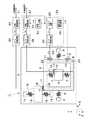
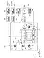
まず、図1は第1の実施の形態による複合センサ1を示している。図において、複合センサ1は、基板2、支持部3,14、振動子4,6,15、支持梁5,7,16、振動発生部8、変位検出部11,17、振動モニタ部20等によって構成されている。 First, FIG. 1 shows a
基板2は、複合センサ1のベース部分を構成している。そして、基板2は、例えばガラス材料等により四角形の平板状に形成され、互いに直交するX軸,Y軸及びZ軸方向のうち、例えばX軸及びY軸方向に沿って水平に延びている。 The
また、基板2上には、例えば導電性を有する低抵抗なシリコン材料等にエッチング加工を施すことによって、支持部3,14、振動子4,6,15、支持梁5,7,16、振動発生部8、変位検出部11,17、振動モニタ部20が形成されている。 Further, on the
支持部3は、基板2の表面に例えば2個設けられている。これら2個の支持部3は、振動子4を挟んでX軸方向の両側に配置されている。そして、後述する可動側の電極10,13,18,22は、支持部3と振動子4,6等とを介してグランドに接続されている。 For example, two
第1の振動子4は、基板2の表面側に位置して、基板2と隙間をもって対向して配置されている。第1の振動子4は、例えば四角形の枠状に形成され、X軸方向に延びる前,後の横枠部4Aと、Y軸方向に延びる左,右の縦枠部4Bとにより構成されている。 The
また、振動子4の外側部位は後述する第1の支持梁5を介して第1の支持部3に連結され、振動子4の内側部位には後述する振動子6が支持梁7を介して連結されている。そして、これらの振動子4,6は基板2に対してZ軸方向に離間し、一定の振動方向(X軸方向)に振動する構成となっている。 Further, the outer portion of the
第1の支持梁5は、第1の振動子4と第1の支持部3とを接続し、X軸方向に向けて振動可能な状態で第1の振動子4を支持している。具体的には、第1の支持梁5は、X軸方向に撓み変形可能に形成され、例えば第1の振動子4のX軸方向の両側にそれぞれ配置されている。そして、支持梁5は、振動子4,6をX軸方向に振動可能に支持し、振動子4がY軸方向に変位するのを規制している。 The
角速度検出用振動子6は、第1の振動子4内に位置して、第1の振動子4に連結した状態で設けられている。具体的には、振動子6は、例えば四角形の板状に形成されている。そして、振動子6は、第2の支持梁7が撓み変形することにより、振動方向と直交する検出方向(Y軸方向)に変位するものである。 The angular
角速度検出用支持梁7は、振動子4,6を接続し、Y軸方向に向けて変位可能な状態で振動子6を支持している。具体的には、支持梁7は、Y軸方向に撓み変形可能に形成され、例えば振動子6のY軸方向の両側にそれぞれ配置されている。そして、支持梁7は、振動子6をY軸方向に変位可能に支持し、この振動子6がX軸方向に変位するのを規制している。 The angular velocity
振動発生部8(振動発生手段)は、基板2と第1の振動子4との間に設けられ、静電力を用いて振動子4,6をX軸方向に振動させる。ここで、振動発生部8は、基板2に設けられた固定側駆動電極9と、振動子4に設けられた可動側駆動電極10とによって構成されている。また、駆動電極9,10は互いに隙間をもって対向している。そして、振動発生部8は、後述の振動制御回路23から駆動信号Vdが入力されることにより、駆動電極9,10間に静電力を発生し、この静電力により振動子4,6をX軸方向に振動させる。 The vibration generator 8 (vibration generator) is provided between the
角速度検出用の変位検出部11(角速度検出用の変位検出手段)は、基板2と振動子6との間に設けられ、振動子6がY軸方向に向けて変位するときの変位量を検出する。ここで、変位検出部11は、基板2に設けられた固定側検出電極12と、振動子6に設けられた可動側駆動電極13とによって構成されている。また、検出電極12,13は互いに隙間をもって対向している。そして、可動側検出電極13は、振動子6と一緒にY軸方向に変位する。これにより、振動子6がY軸方向に変位したときには、検出電極12,13間の静電容量Ccが変化する。 The angular velocity detection displacement detector 11 (angular velocity detection displacement detection means) is provided between the
即ち、変位検出部11は、固定側検出電極12と可動側検出電極13によって平行平板コンデンサとして構成されている。そして、振動子4,6がX軸方向に振動した状態でZ軸周りの角速度Ωが作用すると、振動子6がコリオリ力によってY軸方向に変位する。このため、変位検出部11は、振動子6がY軸方向に変位するときの変位量を、検出電極12,13間の静電容量Ccを用いて検出し、角速度Ωに応じた検出信号を出力する。 That is, the
第2の支持部14は、基板2の表面に位置して例えば2個設けられている。そして、これら2個の第2の支持部14は、後述する振動子15を挟んでY軸方向の両側に配置されている。 For example, two
第2の振動子15は、第1の振動子4の近傍に位置して基板2の表面側に設けられ、基板2と隙間をもって対向している。また、第2の振動子15は、例えば四角形の板状に形成されている。 The
第2の支持梁16は、第2の振動子15と第2の支持部14とを接続し、Y軸方向に向けて振動可能な状態で第2の振動子15を支持している。具体的には、第2の支持梁16は、Y軸方向に撓み変形可能に形成され、例えば第2の振動子15のY軸方向の両側にそれぞれ配置されている。そして、支持梁16は、振動子15をY軸方向に振動可能に支持し、振動子15がX軸方向に変位するのを規制している。 The
加速度検出用の変位検出部17(加速度検出用の変位検出手段)は、第1の振動子4と第2の振動子15との間に設けられ、第2の振動子15がY軸方向に向けて変位するときの変位量を検出する。ここで、変位検出部17は、第1の振動子4に設けられた検出電極18と、第2の振動子15に設けられた検出電極19とによって構成されている。また、検出電極18,19は、互いに隙間をもって対向し、平行平板コンデンサを形成している。 The acceleration detecting displacement detector 17 (acceleration detecting displacement detecting means) is provided between the
そして、検出電極18は第1の振動子4と一緒にX軸方向に変位し、検出電極19は第2の振動子15と一緒にY軸方向に変位する。これにより、第1の振動子4がX軸方向に変位したときには、検出電極18,19間の静電容量Caが変化する。また、第2の振動子15がY軸方向に変位したときにも、検出電極18,19間の静電容量Caが変化する。このため、変位検出部17は、検出電極18,19間の静電容量Caを用いて、第2の振動子15がY軸方向に変位するときの変位量を検出する。 The
振動モニタ部20(振動モニタ手段)は、基板2と第1の振動子4との間に設けられ、第1の振動子4がX軸方向に向けて変位するときの変位量を検出する。ここで、振動モニタ部20は、基板2に設けられた固定側モニタ電極21と、振動子4に設けられた可動側モニタ電極22とによって構成されている。また、モニタ電極21,22は、互いに隙間をもって対向し、平行平板コンデンサを形成している。 The vibration monitoring unit 20 (vibration monitoring means) is provided between the
そして、可動側モニタ電極22は、振動子4と一緒にX軸方向に変位する。これにより、振動子4がX軸方向に変位したときには、モニタ電極21,22間の静電容量Cmが変化する。このため、振動モニタ部20は、第1の振動子4がX軸方向に振動したときの変位量を、モニタ電極21,22間の静電容量Cmを用いてモニタする。 The
次に、振動子4の振動状態を制御する振動制御回路23について説明する。振動制御回路23は、振動モニタ部20によるモニタ信号Vmを用いて振動発生部8に出力する駆動信号Vdを制御する。そして、振動制御回路23は、例えばC−V変換回路(静電容量−電圧変換回路)24、AGC回路(自動利得制御回路)25、駆動信号発生回路26等によって構成されている。 Next, the
C−V変換回路24は、振動モニタ部20に接続され、振動モニタ部20の静電容量Cmの変化を電圧変化に変換し、この電圧変化をモニタ信号Vmとして出力する。 The
C−V変換回路24の出力側には、AGC回路25が接続されている。また、AGC回路25の出力側は、駆動信号発生回路26を介して振動発生部8に接続されている。そして、駆動信号発生回路26は、駆動信号Vdを発生し、この駆動信号Vdを駆動電極9に入力することによって、振動子4,6をX軸方向に振動させる。 An
また、AGC回路25は、C−V変換回路24によるモニタ信号Vmを用いて駆動信号Vdを補正する。これにより、AGC回路25は、例えば周囲温度が変化したときでも、振動子4,6を常に同じ振幅で振動させる。 The
次に、角速度Ωを検出する角速度検出回路27(角速度検出手段)について説明する。角速度検出回路27は、変位検出部11による変位検出信号Vcを振動モニタ部20によるモニタ信号Vmを用いて同期検波し、角速度検出用振動子6に作用する角速度Ωを検出する。そして、角速度検出回路27は、例えばC−V変換回路28、同期検波回路29等によって構成されている。 Next, the angular velocity detection circuit 27 (angular velocity detection means) that detects the angular velocity Ω will be described. The angular
ここで、C−V変換回路28は、C−V変換回路24とほぼ同様に構成され、変位検出部11の静電容量Ccの変化を電圧変化に変換し、この電圧変化を変位検出信号Vcとして出力する。 Here, the
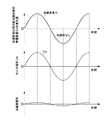
また、同期検波回路29の入力側は、C−V変換回路28に接続されると共に、位相シフト回路30を介してAGC回路25に接続されている。ここで、位相シフト回路30は、AGC回路25を介して出力されるモニタ信号Vmの位相を90°シフトさせた位相シフト信号Vm′を出力する。このとき、振動子4のX軸方向の振動と、角速度Ωによる振動子6のY軸方向の振動とは、互いに位相が90°ずれる。このため、同期検波回路29は、例えばモニタ信号Vmから位相が90°シフトした位相シフト信号Vm′を用いて同期検波する。これにより、同期検波回路29は、図2に示すように、角速度Ωに応じた角速度信号を出力する。 In addition, the input side of the
次に、加速度αを検出する加速度検出回路31(加速度検出手段)について説明する。加速度検出回路31は、変位検出部17による変位検出信号Vaを振動モニタ部20によるモニタ信号Vmを用いて同期検波し、振動子15に作用する加速度αを検出する。そして、加速度検出回路31は、例えばC−V変換回路32、同期検波回路33等によって構成されている。 Next, the acceleration detection circuit 31 (acceleration detection means) that detects the acceleration α will be described. The
ここで、C−V変換回路32は、C−V変換回路24とほぼ同様に構成され、変位検出部17の静電容量Caの変化を電圧変化に変換し、この電圧変化を変位検出信号Vaとして出力する。 Here, the
また、同期検波回路33の入力側は、C−V変換回路32に接続されると共に、AGC回路25に接続されている。このとき、加速度αによって振動子15が変位すると、この振動子15の変位量に応じて変位検出部17の静電容量Caは、振動子4のX軸方向の振動と同期して変化する。このため、同期検波回路33は、例えばモニタ信号Vmを用いて同期検波する。これにより、同期検波回路33は、図3に示すように、加速度αに応じた加速度信号を出力する。 The input side of the
なお、基板2の表面には、振動子4,6,15等を収容した状態で蓋体(図示せず)を設けるのが好ましい。この場合、蓋体内を真空封止することができ、振動子4,6,15に対する空気抵抗を軽減することができる。 In addition, it is preferable to provide a lid (not shown) on the surface of the
本実施の形態による複合センサ1は上述の如き構成を有するもので、次に、その作動について説明する。 The
まず、振動発生部8に駆動信号Vdが出力されると、振動発生部8にX軸方向の静電力が発生し、振動子4,6はX軸方向に振動する。 First, when the drive signal Vd is output to the
これにより、振動子4,6の振動周波数に応じて振動モニタ部20の静電容量Cmが変化し、C−V変換回路24からAGC回路25にモニタ信号Vmが出力される。そして、AGC回路25は、このモニタ信号Vmに応じて補正した駆動信号Vdを振動発生部8に出力し、振動子4,6の振動状態をフィードバック制御する。これにより、周囲の温度等が変化する場合でも、振動子4,6は常に同じ振幅で振動する。 As a result, the capacitance Cm of the
このように、振動子4,6がX軸方向に振動しているときに、複合センサ1にZ軸周りの角速度Ωが加わると、これらの振動子4,6には、下記数1の式に示すY軸方向のコリオリ力Fが加わる。 As described above, when the angular velocity Ω around the Z axis is applied to the

このため、振動子6は、角速度Ωに応じてY軸方向に変位し、角速度検出用の変位検出部11の静電容量Ccが変化する。このとき、C−V変換回路28は、静電容量Ccの変化を変位検出信号Vcに変換する。そして、同期検波回路29は、変位検出信号Vcから位相シフト信号Vm′と同期した信号を検波する。これにより、角速度検出回路27は、図2に示すように、角速度Ωに応じた角速度信号を外部に出力する。なお、振動子4は、Y軸方向に自由度がないため、コリオリ力Fで変位しない。 For this reason, the
一方、振動子4がX軸方向に振動しているときに、複合センサ1にY軸方向の加速度αが加わると、振動子15は加速度αに応じてY軸方向に変位する。このとき、加速度検出用の変位検出部17の静電容量Caが変化するから、C−V変換回路32は、静電容量Caの変化を変位検出信号Vaに変換する。そして、同期検波回路33は、変位検出信号Vaからモニタ信号Vmと同期した信号を検波する。これにより、加速度検出回路31は、図3に示すように、加速度αに応じた加速度信号を外部に出力する。 On the other hand, when the
かくして、本実施の形態では、第1の振動子4がX軸方向に振動した状態でZ軸周りの角速度Ωが作用すると、コリオリ力によって振動子6がY軸方向に変位する。このため、角速度検出用の変位検出部11は振動子6のY軸方向の変位量を検出し、角速度検出回路27は変位検出部11による変位検出信号Vcに対して振動モニタ部20によるモニタ信号Vm(位相シフト信号Vm′)を用いて同期検波処理を行う。これにより、角速度検出回路27は、角速度Ωに応じた角速度信号を出力することができる。 Thus, in the present embodiment, when the angular velocity Ω around the Z axis acts while the
また、Y軸方向の加速度αが作用すると、加速度αによって第2の振動子15がY軸方向に変位する。このとき、加速度検出用の変位検出部17は、第2の振動子15が第1の振動子4に対してY軸方向に変位するときの変位量を検出する。そして、加速度検出回路31は、変位検出部17による変位検出信号Vaに対して振動モニタ部20によるモニタ信号Vmを用いて同期検波処理を行う。これにより、加速度検出回路31は、加速度αに応じた加速度信号を出力することができる。 When the acceleration α in the Y-axis direction is applied, the
特に、本実施の形態では、振動子4,6とは別個に振動子15を設けると共に、振動子15を支持梁16を用いて支持する構成とした。このため、振動子4,6および支持梁5,7とは独立して、振動子15および支持梁16を設計することができる。この結果、振動子4,6および支持梁5,7は角速度Ωの検出に適した質量や剛性にすることができると共に、振動子15および支持梁16は加速度αの検出に適した質量や剛性にすることができる。これにより、角速度Ωおよび加速度αの両方を高感度に検出することができる。 In particular, in the present embodiment, the
また、加速度検出回路31は、加速度検出用の変位検出部17による変位検出信号Vaを振動モニタ部20によるモニタ信号Vmを用いて同期検波する構成としたから、第1の振動子4の振動周波数とは異なる周波数成分の信号を除去することができる。このため、電気的な外部雑音等を容易に除去することができ、第1の振動子4を停止させた状態で加速度を検出した場合に比べて、加速度αの検出精度を高めることができる。 Further, since the
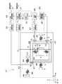
次に、図4は第2の実施の形態を示している。そして、本実施の形態の特徴は、第2の振動子は第1の振動子の振動方向と同じX軸方向に変位可能に設ける構成としたことにある。なお、本実施の形態では前記第1の実施の形態と同一の構成要素に同一の符号を付し、その説明を省略するものとする。 Next, FIG. 4 shows a second embodiment. A feature of the present embodiment is that the second vibrator is configured to be displaceable in the same X-axis direction as the vibration direction of the first vibrator. In the present embodiment, the same components as those in the first embodiment are denoted by the same reference numerals, and the description thereof is omitted.
複合センサ41は、基板2、支持部3,42、振動子4,6,43、支持梁5,7,44、振動発生部8、変位検出部11,45、振動モニタ部20等によって構成されている。 The
第2の支持部42は、基板2の表面に位置して例えば2個設けられている。そして、これら2個の第2の支持部42は、後述する振動子43を挟んでX軸方向の両側に配置されている。 For example, two
第2の振動子43は、第1の振動子4の近傍に位置して基板2の表面側に設けられ、基板2と隙間をもって対向している。また、第2の振動子43は、例えば四角形の板状に形成されている。 The
第2の支持梁44は、第2の振動子43と第2の支持部42とを接続し、X軸方向に向けて振動可能な状態で第2の振動子43を支持している。具体的には、第2の支持梁44は、X軸方向に撓み変形可能に形成され、例えば第2の振動子43のX軸方向の両側にそれぞれ配置されている。そして、支持梁44は、振動子43をX軸方向に振動可能に支持し、振動子43がY軸方向に変位するのを規制している。 The
加速度検出用の変位検出部45(加速度検出用の変位検出手段)は、第1の振動子4と第2の振動子43との間に設けられ、第2の振動子43がX軸方向に向けて変位するときの変位量を検出する。ここで、変位検出部45は、第1の振動子4に設けられた検出電極46と、第2の振動子43に設けられた検出電極47とによって構成されている。また、検出電極46,47は、互いに隙間をもって対向し、平行平板コンデンサを形成している。そして、変位検出部45は、加速度検出回路31に接続されている。 The acceleration detection displacement detector 45 (acceleration detection displacement detection means) is provided between the
また、検出電極46は第1の振動子4と一緒にX軸方向に変位し、検出電極47は第2の振動子43と一緒にX軸方向に変位する。これにより、第1,第2の振動子4,43がX軸方向に変位したときには、検出電極46,47間の静電容量Caが変化する。このため、変位検出部45は、検出電極46,47間の静電容量Caを用いて、第2の振動子43がX軸方向に変位するときの変位量を検出する。 The
かくして、このように構成される本実施の形態でも、前記第1の実施の形態とほぼ同様の作用効果を得ることができる。特に、本実施の形態では、第2の振動子43は第1の振動子4の振動方向と同じX軸方向に変位可能に設ける構成としたから、第1の振動子4の振動方向の加速度を検出することができる。 Thus, in the present embodiment configured as described above, it is possible to obtain substantially the same operational effects as those of the first embodiment. In particular, in the present embodiment, since the
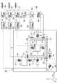
次に、図5は第3の実施の形態を示している。そして、本実施の形態の特徴は、第2の振動子をY軸方向に変位可能に設けるのに加えて、第3の振動子をX軸方向に変位可能に設ける構成としたことにある。なお、本実施の形態では前記第1の実施の形態と同一の構成要素に同一の符号を付し、その説明を省略するものとする。 Next, FIG. 5 shows a third embodiment. A feature of this embodiment is that, in addition to providing the second vibrator so as to be displaceable in the Y-axis direction, the third vibrator is provided so as to be displaceable in the X-axis direction. In the present embodiment, the same components as those in the first embodiment are denoted by the same reference numerals, and the description thereof is omitted.
複合センサ51は、基板2、支持部3,14,52、振動子4,6,15,53、支持梁5,7,16,54、振動発生部8、変位検出部11,17,55、振動モニタ部20等によって構成されている。 The
第3の支持部52は、基板2の表面に位置して例えば2個設けられている。そして、これら2個の第3の支持部52は、後述する振動子53を挟んでX軸方向の両側に配置されている。 For example, two
第3の振動子53は、第1の振動子4の近傍に位置して基板2の表面側に設けられ、基板2と隙間をもって対向している。また、第3の振動子53は、第2の振動子15と異なる位置に配置され、例えば四角形の板状に形成されている。 The
第3の支持梁54は、第3の振動子53と第3の支持部52とを接続し、X軸方向に向けて振動可能な状態で第3の振動子53を支持している。具体的には、第3の支持梁54は、X軸方向に撓み変形可能に形成され、例えば第3の振動子53のX軸方向の両側にそれぞれ配置されている。そして、支持梁54は、振動子53をX軸方向に振動可能に支持し、振動子53がY軸方向に変位するのを規制している。 The
加速度検出用の変位検出部55(加速度検出用の変位検出手段)は、第1の振動子4と第3の振動子53との間に設けられ、第3の振動子53がX軸方向に向けて変位するときの変位量を検出する。ここで、変位検出部55は、第1の振動子4に設けられた検出電極56と、第3の振動子53に設けられた検出電極57とによって構成されている。また、検出電極56,57は、互いに隙間をもって対向し、平行平板コンデンサを形成している。そして、変位検出部55は、加速度検出回路31と同様に構成された他の加速度検出回路58に接続されている。 The acceleration detection displacement detection unit 55 (acceleration detection displacement detection means) is provided between the
かくして、このように構成される本実施の形態でも、前記第1の実施の形態とほぼ同様の作用効果を得ることができる。特に、本実施の形態では、第2の振動子15をY軸方向に変位可能に設けるのに加えて、第3の振動子53をX軸方向に変位可能に設ける構成としたから、互いに直交する2軸方向の加速度を一緒に検出することができる。 Thus, in the present embodiment configured as described above, it is possible to obtain substantially the same operational effects as those of the first embodiment. In particular, in the present embodiment, since the
次に、図6は第4の実施の形態を示している。そして、本実施の形態の特徴は、角速度検出用振動子をZ軸方向に変位可能に設け、Y軸周りの角速度Ωを検出する構成としたことにある。なお、本実施の形態では前記第1の実施の形態と同一の構成要素に同一の符号を付し、その説明を省略するものとする。 Next, FIG. 6 shows a fourth embodiment. The feature of this embodiment is that the angular velocity detecting vibrator is provided so as to be displaceable in the Z-axis direction, and the angular velocity Ω around the Y-axis is detected. In the present embodiment, the same components as those in the first embodiment are denoted by the same reference numerals, and the description thereof is omitted.
複合センサ61は、基板2、支持部3,14、振動子4,62,15、支持梁5,63,16、振動発生部8、変位検出部64,17、振動モニタ部20等によって構成されている。 The
角速度検出用振動子62は、その四隅から延びる角速度検出用支持梁63によってZ軸方向に変位可能に設けられている。また、角速度検出用振動子62と基板2との間には、例えば平行平板コンデンサ等からなる角速度検出用の変位検出部64が設けられている。そして、変位検出部64は、角速度検出回路27に接続されている。 The angular
かくして、このように構成される本実施の形態でも、前記第1の実施の形態とほぼ同様の作用効果を得ることができる。特に、本実施の形態では、角速度検出用振動子62をZ軸方向に変位可能に設ける構成としたので、変位検出部64等を用いることによって、Y軸周りの角速度Ωを検出することができる。 Thus, in the present embodiment configured as described above, it is possible to obtain substantially the same operational effects as those of the first embodiment. In particular, in this embodiment, since the angular
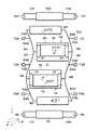
次に、図7ないし図12は第5の実施の形態を示している。そして、本実施の形態の特徴は、第1の振動子はY軸方向に複数並んで配置し、第1の支持梁は該複数の第1の振動子を互いに連結すると共に、振動発生部は互いに隣合う第1の振動子を逆位相で振動させる構成としたことにある。 Next, FIG. 7 to FIG. 12 show a fifth embodiment. A feature of the present embodiment is that a plurality of first vibrators are arranged side by side in the Y-axis direction, a first support beam connects the plurality of first vibrators to each other, and a vibration generator is The first vibrator adjacent to each other is oscillated with an opposite phase.
図において、複合センサ71は、基板72、支持部73,98,101、質量部74,78,82,83,99,102、支持梁77,81,84,100,103、振動発生部86,89、変位検出部92,95,104,107、振動モニタ部110,113等によって構成されている。 In the figure, the
基板72は、例えばシリコン材料、ガラス材料等により平板状に形成され、互いに直交するX軸,Y軸及びZ軸のうち、例えばX軸とY軸とに沿って水平に延びると共に、Z軸と垂直に配置されている。 The
また、基板72上には、例えば導電性を有する低抵抗なシリコン材料等にエッチング加工を施すことによって、支持部73,98,101、質量部74,78,82,83,99,102、支持梁77,81,84,100,103、振動発生部86,89、変位検出部92,95,104,107、振動モニタ部110,113等が形成されている。 Further, on the
中央支持部73は、第1の支持部を構成し、基板72上に位置してX軸方向の両側に設けられている。ここで、各中央支持部73は、基板72上に固定されY軸方向に延びた台座部73Aと、該台座部73Aに設けられ基板72から離れた位置で連結支持梁84の節部84Aに連結された3個の腕部73Bとによって構成されている。 The
ここで、各腕部73Bは、質量部74,78,82,83、支持梁77,81,84等を基板72から離間した状態に保持している。また、腕部73Bは、各質量部等を連結支持梁84の節部84A(振動の節)の位置で支持する。このため、これらの振動が節部84Aの位置で打消されるようになり、基板72に振動が伝わるのを抑制する。 Here, each
第1の中央質量部74は、基板72と隙間をもって対向して配置されている。また、第1の中央質量部74は、Y軸方向に並んで配置された4個の質量部74,78,82,83のうち、第2の中央質量部78と共に中央寄りに配置されている。また、中央質量部74は、四角形の枠状に形成された第1の振動子としての外側枠体75と、該外側枠体75の内側に配置された四角形の枠状体からなる角速度検出用振動子としての内側枠体76と、該内側枠体76の四隅と外側枠体75との間に設けられた例えば4本の角速度検出用支持梁77とにより構成されている。 The first
ここで、外側枠体75は、中央質量部74がX軸方向(振動方向)に振動するときに、後述する連結支持梁84の撓み変形がY軸方向(検出方向)の変位となって内側枠体76に伝わるのを遮断している。また、角速度検出用支持梁77は、X軸方向に延びてY軸方向に撓み変形可能に形成され、内側枠体76をY軸方向に変位可能に支持すると共に、内側枠体76がX軸方向に変位するのを規制している。 Here, when the
第2の中央質量部78は、中央質量部74とほぼ同様に、外側枠体79(第1の振動子)、内側枠体80(角速度検出用振動子)および角速度検出用支持梁81により構成されている。そして、内側枠体80は、角速度検出用支持梁81が撓み変形することによりY軸方向に変位可能となっている。 The second
第1,第2の外側質量部82,83は、Y軸方向に対して中央質量部74,78の外側に配置され、第1の振動子をそれぞれ構成している。外側質量部82,83は、X軸方向に延びる直線状の質量体として形成され、その長さ方向の両端側は各連結支持梁84にそれぞれ連結されている。 The first and second
連結支持梁84は、質量部74,78,82,83を挟んでX軸方向の両側に配置され、第1の支持梁を構成している。各連結支持梁84は、ばね性を有する細幅な梁として形成され、Y軸方向に直線状に延びると共に、X軸方向に撓み変形可能となっている。また、各連結支持梁84の長さ方向途中部位には、高い剛性を有する幅広な連結部85を介して質量部74,78の外側枠体75,79が連結され、連結支持梁84の長さ方向両端側には外側質量部82,83が連結されている。 The connection support beams 84 are disposed on both sides in the X-axis direction with the
これにより、4個の質量部74,78,82,83は、互いに梯子状に連結された連結質量部を構成すると共に、Y軸方向に直線状に並んだ状態で各連結支持梁84によりX軸方向に振動可能に支持されている。また、これらの質量部74,78,82,83は、質量部全体の重心Gを挟んでほぼ対称に配置されている。 As a result, the four
そして、後述の振動発生部86,89に駆動信号をそれぞれ印加したときには、図7および図11に示すように、互い隣合う質量部74,83と質量部78,82とが、これら全体の重心Gをほぼ一定の位置に保持しつつ、逆位相(位相が180°ずれた状態)でX軸方向に振動する。即ち、例えば質量部74,83がX軸方向に沿って矢示a1方向に振動するときには、質量部78,82がこれと逆向きの矢示a2方向に振動する。 When a drive signal is applied to
このように、隣合う質量部同士が互いに逆位相で振動する振動モードは、複合センサ71が作動するときの正規の振動モードとして予め定められているものである。この振動モードにおいて、質量部74,83と質量部78,82とは、重心Gを中心として対称な位置で安定的に振動できると共に、重心Gの周囲でバランスよく振動することによって基板72への振動伝達を抑えることができる。また、正規の振動モードでは、各連結支持梁84がX軸方向に略S字状をなして撓み変形しつつ、くねるように振動し、その長さ方向途中部位には、振動の節となってほぼ一定の位置を保持する例えば3箇所の節部84Aがそれぞれ形成される。 Thus, the vibration mode in which adjacent mass parts vibrate in mutually opposite phases is predetermined as a normal vibration mode when the
第1の振動発生部86(振動発生手段)は、基板72と第1の外側質量部82との間に設けられ、静電力を用いて第1の外側質量部82をX軸方向に振動させる。ここで、振動発生部86は、X軸方向に離間して2箇所に配置されている。そして、各振動発生部86は、基板72に設けられた固定側駆動電極87と、外側質量部82に設けられた可動側駆動電極88とによって構成されている。 The first vibration generating unit 86 (vibration generating means) is provided between the
固定側駆動電極87は、例えば複数の電極板87Aを有する櫛歯状電極によって構成されている。また、可動側駆動電極88も、例えば複数の電極板88Aを有する櫛歯状電極からなり、各電極板87A,88Aは、Y軸方向の隙間をもって互いに噛合している。 The fixed
第2の振動発生部89(振動発生手段)は、基板72と第2の外側質量部83との間に設けられ、静電力を用いて第2の外側質量部83をX軸方向に振動させる。ここで、振動発生部89は、X軸方向に離間して2箇所に配置されている。そして、各振動発生部89は、基板72に設けられた固定側駆動電極90と、外側質量部83に設けられた可動側駆動電極91とによって構成されている。 The second vibration generating unit 89 (vibration generating unit) is provided between the
固定側駆動電極90は、例えば複数の電極板90Aを有する櫛歯状電極によって構成されている。また、可動側駆動電極91も、例えば複数の電極板91Aを有する櫛歯状電極からなり、各電極板90A,91Aは、Y軸方向の隙間をもって互いに噛合している。 The fixed
そして、振動発生部86,89は、後述の振動制御回路116から駆動信号Vdが印加されることにより静電力を発生し、これを駆動力として外側質量部82,83をX軸方向に振動させる。この場合、例えば振動発生部86が矢示a2方向の駆動力F1を発生するときに、振動発生部89は、これと逆方向(逆位相)となる矢示a1方向の駆動力F2を発生する。 The
第1の角速度検出用の変位検出部92(角速度検出用の変位検出手段)は、基板72と中央質量部74との間に設けられ、内側枠体76がY軸方向に向けて変位するときの変位量を検出する。ここで、変位検出部92は、基板72に設けられた固定側検出電極93と、内側枠体76に設けられた可動側検出電極94とによって構成されている。 The first angular velocity detecting displacement detecting unit 92 (angular velocity detecting displacement detecting means) is provided between the
また、固定側検出電極93は、Y軸方向に間隔をもってX軸方向に延びる複数の電極板93Aを有し、第1の中央質量部74の内側枠体76内に配置されている。一方、可動側検出電極94は、固定側検出電極93に対応して中央質量部74の内側枠体76に設けられ、固定側検出電極93の各電極板93AとY軸方向の隙間をもって噛合する複数の電極板94Aを有している。これにより、電極板93A,94Aは平行平板コンデンサを構成している。 The fixed
そして、変位検出部92は、内側枠体76がZ軸周りの角速度ΩによってY軸方向に変位するときに、その変位量を検出電極93,94間の静電容量Cc1の変化により角速度Ωとして検出する。 When the
第2の角速度検出用の変位検出部95(角速度検出用の変位検出手段)は、基板72と中央質量部78との間に設けられ、内側枠体80がY軸方向に向けて変位するときの変位量を検出する。ここで、変位検出部95は、変位検出部92とほぼ同様に、基板72に設けられた固定側検出電極96と、内側枠体80に設けられた可動側検出電極97とによって構成されている。 The second angular velocity detection displacement detection unit 95 (angular velocity detection displacement detection means) is provided between the
また、固定側検出電極96は、Y軸方向に間隔をもってX軸方向に延びる複数の電極板96Aを有し、第2の中央質量部78の内側枠体80内に配置されている。一方、可動側検出電極97は、固定側検出電極96に対応して中央質量部78の内側枠体80に設けられ、固定側検出電極96の各電極板96AとY軸方向の隙間をもって噛合する複数の電極板97Aを有している。これにより、電極板96A,97Aは平行平板コンデンサを構成している。 The fixed
そして、変位検出部95は、内側枠体80がZ軸周りの角速度ΩによってY軸方向に変位するときに、その変位量を検出電極96,97間の静電容量Cc2の変化により角速度Ωとして検出する。 Then, when the
ここで、第1の変位検出部92は、例えば中央質量部74の内側枠体76がY軸方向に沿って矢示b1方向に変位するときに検出電極93,94間の静電容量Cc1が増大し、内側枠体76が矢示b2方向に変位するときに静電容量Cc1が減少する。これと逆に、第2の変位検出部95は、例えば中央質量部78の内側枠体80が矢示b1方向に変位するときに検出電極96,97間の静電容量Cc2が減少し、内側枠体80が矢示b2方向に変位するときに静電容量Cc2が増大する。 Here, the first
第1の外側支持部98は、第2の支持部を構成し、重心Gを中心としたときに第1の外側質量部82よりもY軸方向の外側に配置され、基板72の表面に例えば2個設けられている。そして、これら2個の外側支持部98は、後述する非連結質量部99を挟んでX軸方向の両側に配置されている。 The first
第1の非連結質量部99は、第2の振動子を構成し、外側質量部82の近傍に位置して基板72の表面側に設けられ、基板72と隙間をもって対向している。また、第1の非連結質量部99は、例えばC字状の枠体によって形成されている。 The first unconnected
第1の外側支持梁100は、第2の支持梁を構成し、非連結質量部99と外側支持部98とを接続し、Y軸方向に向けて振動可能な状態で非連結質量部99を支持している。具体的には、外側支持梁100は、X軸方向に折り返して延び、Y軸方向に撓み変形可能なばね性を有している。そして、外側支持梁100は、例えば非連結質量部99のX軸方向の両側に2本ずつ合計4本配置されている。これにより、外側支持梁100は、非連結質量部99をY軸方向に振動可能に支持し、非連結質量部99がX軸方向に変位するのを規制している。 The first
また、第1の外側支持部98、第1の非連結質量部99、第1の外側支持梁100に対して質量部74,78,82,83を挟んでY軸方向の反対側の位置には、第2の外側支持部101、第2の非連結質量部102、第2の外側支持梁103が設けられている。このとき、第2の外側支持部101、第2の非連結質量部102、第2の外側支持梁103は、第1の外側支持部98、第1の非連結質量部99、第1の外側支持梁100とほぼ同様に形成され、第2の支持部、第2の振動子、第2の支持梁をそれぞれ構成している。このため、非連結質量部102は、外側支持梁103を用いて外側支持部101に接続されると共に、Y軸方向に振動可能に支持されている。 Further, the first
また、非連結質量部99,102は、外側質量部82,83に対してY軸方向の反対側の位置に配置されている。このため、Y軸方向に加速度αが作用したときには、非連結質量部99,102は外側質量部82,83に対して互いに逆方向に変位する。即ち、非連結質量部99が外側質量部82に接近するときには、非連結質量部102は外側質量部83から離れる。また、非連結質量部99が外側質量部82から離れるときには、非連結質量部102は外側質量部83に接近する。 Further, the
第1の加速度検出用の変位検出部104(加速度検出用の変位検出手段)は、第1の外側質量部82と第1の非連結質量部99との間に設けられ、非連結質量部99がY軸方向に向けて変位するときの変位量を検出する。ここで、変位検出部104は、図8に示すように、外側質量部82に設けられた検出電極105と、非連結質量部99に設けられた検出電極106とによって構成されている。 The first acceleration detection displacement detection unit 104 (acceleration detection displacement detection means) is provided between the first
また、検出電極105は、例えばT字状に形成された腕部105Aと、該腕部105Aおよび外側質量部82に設けられた複数個の電極部105Bとによって構成されている。このとき、腕部105Aは、その基端側が外側質量部82に接続されると共に、その先端側が枠状をなす非連結質量部99の内部に挿入されている。また、各電極部105Bは、非連結質量部99に向けて突出した突起状に形成され、例えばY軸方向のうち図7中のb2方向に向けて突出している。 In addition, the
一方、検出電極106は、外側質量部82と腕部105Aとの間に挿入された腕部106Aと、該腕部106Aおよび非連結質量部99の内部に設けられた複数個の電極部106Bとによって構成されている。このとき、各電極部106Bは、検出電極105の電極部105Bと対応した位置に配置されている。また、各電極部106Bは、外側質量部82に向けて突出した突起状に形成され、例えばY軸方向のうち図7中のb1方向に向けて突出している。そして、電極部105B,106Bは、Y軸方向の隙間をもって互いに対向し、平行平板コンデンサを形成している。 On the other hand, the
また、検出電極105は外側質量部82と一緒にX軸方向に変位する。これにより、外側質量部82がX軸方向に変位したときには、検出電極105,106の対向面積が変化するから、この対向面積に応じて検出電極105,106間の静電容量Ca1が変化する。ここで、電極部105B,106Bは、外側質量部82が中立状態となったときに、例えば突出端面のうち半分程度が部分的に対向するように、X軸方向に対して互いに位置ずれして配置されている。そして、外側質量部82が振動発生部86によって例えば図7中のa1方向に変位したときには、電極部105B,106Bの対向面積が減少する。一方、外側質量部82が振動発生部86によって例えば図7中のa2方向に変位したときには、電極部105B,106Bの対向面積が増加する。これにより、図9に示すように、外側質量部82がX軸方向に振動するときには、検出電極105,106間の静電容量Ca1は、外側質量部82の振動周期(駆動周期)と一致して変化する。 Further, the
また、検出電極106は非連結質量部99と一緒にY軸方向に変位する。そして、非連結質量部99がY軸方向に変位したときには、検出電極105,106間の距離寸法が変化するから、この距離寸法に応じて検出電極105,106間の静電容量Ca1が変化する。このため、変位検出部104は、検出電極105,106間の静電容量Ca1を用いて、非連結質量部99がY軸方向に変位するときの変位量を検出する。 Further, the
第2の加速度検出用の変位検出部107(加速度検出用の変位検出手段)は、図7に示すように、第2の外側質量部83と第2の非連結質量部102との間に設けられ、非連結質量部102がY軸方向に向けて変位するときの変位量を検出する。ここで、変位検出部107は、変位検出部104をほぼ同様に、外側質量部83に設けられた検出電極108と、非連結質量部102に設けられた検出電極109とによって構成されている。 The second acceleration detection displacement detection unit 107 (acceleration detection displacement detection means) is provided between the second
このため、検出電極108は、非連結質量部102の内部に挿入されたT字状の腕部108Aと、該腕部108Aおよび外側質量部83に設けられた複数個の電極部108Bとによって構成されている。そして、各電極部108Bは、非連結質量部102に向けて突出した突起状に形成され、例えばY軸方向のうち図7中のb1方向に向けて突出している。 Therefore, the detection electrode 108 is configured by a T-shaped
一方、検出電極109は、外側質量部83と腕部108Aとの間に挿入された腕部109Aと、該腕部109Aおよび非連結質量部102の内部に設けられた複数個の電極部109Bとによって構成されている。このとき、各電極部109Bは、検出電極108の電極部108Bと対応した位置に配置されている。また、各電極部109Bは、外側質量部83に向けて突出した突起状に形成され、例えばY軸方向のうち図7中のb2方向に向けて突出している。そして、電極部108B,109Bは、Y軸方向の隙間をもって互いに対向し、平行平板コンデンサを形成している。このため、変位検出部107は、検出電極108,109間の静電容量Ca2を用いて、非連結質量部102がY軸方向に変位するときの変位量を検出する。 On the other hand, the
また、電極部108B,109Bは、電極部105B,106Bと同様に、外側質量部83が中立状態となったときに、例えば突出端面のうち半分程度が部分的に対向するように、X軸方向に対して互いに位置ずれして配置されている。そして、外側質量部83が振動発生部89によって例えば図7中のa1方向に変位したときには、電極部108B,109Bの対向面積が増加する。一方、外側質量部83が振動発生部89によって例えば図7中のa2方向に変位したときには、電極部108B,109Bの対向面積が減少する。これにより、外側質量部83がX軸方向に振動するときには、検出電極108,109間の静電容量Ca2は、外側質量部83の振動周期(駆動周期)と一致して変化する。 Similarly to the
ここで、第1の変位検出部104は、例えば非連結質量部99がY軸方向に沿って矢示b1方向に変位するときに検出電極105,106間の静電容量Ca1が増大し、さらに振幅が大きくなる。非連結質量部99が矢示b2方向に変位するときに静電容量Ca1が減少し、さらに振幅が小さくなる。これと逆に、第2の変位検出部107は、例えば非連結質量部102が矢示b1方向に変位するときに検出電極108,109間の静電容量Ca2が減少し、さらに振幅が小さくなる。非連結質量部102が矢示b2方向に変位するときに静電容量Ca2が増大し、さらに振幅が大きくなる。 Here, in the first
第1の振動モニタ部110(振動モニタ手段)は、基板72と第1の外側質量部82との間に設けられ、外側質量部82がX軸方向に向けて変位するときの変位量を検出する。ここで、振動モニタ部110は、基板72に設けられた固定側モニタ電極111と、外側質量部82に設けられた可動側モニタ電極112とによって構成されている。また、モニタ電極111,112は、例えば櫛歯状電極によって構成され、隙間をもって互いに噛合している。 The first vibration monitoring unit 110 (vibration monitoring unit) is provided between the
第2の振動モニタ部113(振動モニタ手段)は、基板72と第2の外側質量部83との間に設けられ、外側質量部83がX軸方向に向けて変位するときの変位量を検出する。ここで、振動モニタ部113は、基板72に設けられた固定側モニタ電極114と、外側質量部83に設けられた可動側モニタ電極115とによって構成されている。また、モニタ電極114,115は、例えば櫛歯状電極によって構成され、隙間をもって互いに噛合している。 The second vibration monitoring unit 113 (vibration monitoring unit) is provided between the
そして、第1の振動モニタ部110は、例えば外側質量部82がX軸方向に沿って矢示a1方向に変位するときにモニタ電極111,112間の静電容量Cm1が減少し、外側質量部82が矢示a2方向に変位するときに静電容量Cm1が増大する。これと逆に、第2の振動モニタ部113は、例えば外側質量部83が矢示a1方向に変位するときにモニタ電極114,115間の静電容量Cm2が増大し、外側質量部83が矢示a2方向に変位するときに静電容量Cm2が減少する。 The first
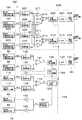
次に、図10を参照しつつ、質量部74,78,82,83の振動状態を制御する振動制御回路116について説明する。振動制御回路116は、振動モニタ部110,113によるモニタ信号Vmを用いて振動発生部86,89に出力する駆動信号Vdを制御する。そして、振動制御回路116は、C−V変換回路117,118、差動増幅器119、AGC回路120、駆動信号発生回路121等によって構成されている。 Next, the
C−V変換回路117,118は振動モニタ部110,113の出力側にそれぞれ接続されている。そして、C−V変換回路117,118は、振動モニタ部110,113の静電容量Cm1,Cm2の変化を電圧変化に変換し、これらの電圧変化を予備モニタ信号Vm1,Vm2としてそれぞれ出力する。また、C−V変換回路117,118の出力側には、差動増幅器119が接続されている。 The
ここで、質量部74,83と質量部78,82とが互いに逆位相で振動しているときには、これら2つの予備モニタ信号Vm1,Vm2は互いに逆位相となる。このため、2つの予備モニタ信号Vm1,Vm2は差動増幅器119によって差動増幅され、最終的なモニタ信号VmとしてAGC回路120に出力される。 Here, when the
AGC回路120の出力側は、駆動信号Vdを出力する駆動信号発生回路121に接続されている。そして、AGC回路120は、モニタ信号Vmが一定となるようにゲインを調整する。また、駆動信号発生回路121は、増幅器122を介して第1の振動発生部86に接続されると共に、反転増幅器123を介して第2の振動発生部89に接続される。これにより、駆動信号発生回路121は、振動発生部86,89に対して互いに逆位相となる駆動信号Vdを入力し、振動発生部86,89は、質量部74,83と質量部78,82とを互いに逆位相で振動させる。 The output side of the
次に、角速度Ωを検出する角速度検出回路124(角速度検出手段)について説明する。角速度検出回路124は、変位検出部92,95による変位検出信号Vcを振動モニタ部110,113によるモニタ信号Vmを用いて同期検波し、内側枠体76,80に作用する角速度Ωを検出する。そして、角速度検出回路124は、例えばC−V変換回路125,126、差動増幅器127、同期検波回路128等によって構成されている。 Next, the angular velocity detection circuit 124 (angular velocity detection means) that detects the angular velocity Ω will be described. The angular
C−V変換回路125,126は変位検出部92,95の出力側にそれぞれ接続されている。そして、C−V変換回路125,126は、変位検出部92,95の静電容量Cc1,Cc2の変化を電圧変化に変換し、これらの電圧変化を予備的な変位検出信号Vc1,Vc2としてそれぞれ出力する。また、C−V変換回路125,126の出力側には、差動増幅器127が接続されている。 The
ここで、質量部74,78が互いに逆位相で振動している状態で、角速度Ωが作用したときには、内側枠体76,80はY軸方向に対して互いに逆方向に変位する(図11参照)。このとき、2つの予備的な変位検出信号Vc1,Vc2は互いに逆位相となる。このため、2つの予備的な変位検出信号Vc1,Vc2は差動増幅器127によって差動増幅され、最終的な変位検出信号Vcとして同期検波回路128に出力される。 Here, when the angular velocity Ω is applied in a state where the
同期検波回路128の入力側は、差動増幅器127に接続されると共に、位相シフト回路129を介してAGC回路120に接続されている。また、同期検波回路128の出力側には、角速度信号を取り出すための低域通過フィルタ(LPF)130が接続されると共に、LPF130の出力側にはゲインおよびオフセットを調整するための調整回路131が接続されている。ここで、位相シフト回路129は、AGC回路120を介して出力されるモニタ信号Vmの位相を90°シフトさせた位相シフト信号Vm′を出力する。これにより、同期検波回路128は、変位検出信号Vcから位相シフト信号Vm′を用いて同期検波し、LPF130、調整回路131を介して角速度Ωに応じた角速度信号を出力する。 The input side of the
次に、加速度αを検出する加速度検出回路132(加速度検出手段)について説明する。加速度検出回路132は、変位検出部104,107による変位検出信号Vaを振動モニタ部110,113によるモニタ信号Vmを用いて同期検波し、質量部99,102に作用する加速度αを検出する。そして、加速度検出回路132は、例えばC−V変換回路133,134、差動増幅器135、同期検波回路136等によって構成されている。 Next, the acceleration detection circuit 132 (acceleration detection means) that detects the acceleration α will be described. The
C−V変換回路133,134は変位検出部104,107の出力側にそれぞれ接続されている。そして、C−V変換回路133,134は、変位検出部104,107の静電容量Ca1,Ca2の変化を電圧変化に変換し、これらの電圧変化を予備的な変位検出信号Va1,Va2としてそれぞれ出力する。また、C−V変換回路133,134の出力側には、差動増幅器135が接続されている。 The
ここで、Y軸方向に加速度αが作用したときには、非連結質量部99,102は外側質量部82,83に対して互いに逆方向に変位する(図12参照)。このとき、2つの予備的な変位検出信号Va1,Va2は互いに逆位相となる。このため、2つの予備的な変位検出信号Va1,Va2は差動増幅器135によって差動増幅され、最終的な変位検出信号Vaとして同期検波回路136に出力される。 Here, when the acceleration α is applied in the Y-axis direction, the
同期検波回路136の入力側は、差動増幅器135に接続されると共に、AGC回路120に接続されている。また、同期検波回路136の出力側には、加速度信号を取り出すための低域通過フィルタ(LPF)137が接続されると共に、LPF137の出力側にはゲインおよびオフセットを調整するための調整回路138が接続されている。このとき、加速度αによって非連結質量部99,102が変位すると、この非連結質量部99,102の変位量に応じて変位検出部104,107の静電容量Ca1,Ca2は、質量部74,78,82,83のX軸方向の振動と同期して変化する。このため、同期検波回路136は、変位検出信号Vaからモニタ信号Vmを用いて同期検波し、LPF137、調整回路138を介して加速度αに応じた加速度信号を出力する。 The input side of the
本実施の形態による複合センサ71は上述の如き構成を有するもので、次にその作動について説明する。 The
まず、振動発生部86,89に駆動信号Vdが出力されると、振動発生部86,89にX軸方向の静電力が発生し、質量部74,78,82,83はX軸方向に振動する。このとき、振動発生部86,89は、隣合う質量部74,83と質量部78,82とを互いに逆位相となるように振動させる。また、振動制御回路116は、振動モニタ部110,113によるモニタ信号Vmを用いて駆動信号Vdを制御し、質量部74,78,82,83が常に同じ振幅で振動させる。 First, when the drive signal Vd is output to the
このように、質量部74,83がX軸方向に振動しているときに、複合センサ71にZ軸周りの角速度Ωが加わると、内側枠体76,80には、第1の実施の形態と同様に、Y軸方向のコリオリ力Fが加わる。 As described above, when the
このとき、内側枠体76,80は、角速度Ωに応じてY軸方向に変位する。これにより、角速度検出用の変位検出部92,95の静電容量Cc1,Cc2が変化するから、C−V変換回路125,126は、静電容量Cc1,Cc2の変化を予備的な変位検出信号Vc1,Vc2に変換する。このとき、質量部74,78はX軸方向に沿って互いに逆位相で振動しているから、予備的な変位検出信号Vc1,Vc2は互いに逆位相となる。このため、差動増幅器127は、予備的な変位検出信号Vc1,Vc2の差を演算し、最終的な変位検出信号Vcを出力する。そして、同期検波回路128は、変位検出信号Vcから位相シフト信号Vm′と同期した信号を検波する。これにより、角速度検出回路124は、角速度Ωに応じた角速度信号を外部に出力する。 At this time, the
一方、質量部82,83がX軸方向に振動しているときに、複合センサ71にY軸方向の加速度αが加わると、非連結質量部99,102は加速度αに応じてY軸方向に変位する。これにより、加速度検出用の変位検出部104,107の静電容量Ca1,Ca2が変化するから、C−V変換回路133,134は、静電容量Ca1,Ca2の変化を予備的な変位検出信号Va1,Va2に変換する。このとき、非連結質量部99,102は質量部82,83に対してY軸方向に沿って互いに逆位置に配置されているから、予備的な変位検出信号Va1,Va2は互いに逆位相となる。このため、差動増幅器135は、予備的な変位検出信号Va1,Va2の差を演算し、最終的な変位検出信号Vaを出力する。そして、同期検波回路136は、変位検出信号Vaからモニタ信号Vmと同期した信号を検波する。これにより、加速度検出回路132は、加速度αに応じた加速度信号を外部に出力する。 On the other hand, when the
かくして、本実施の形態でも、第1の実施の形態と同様に、角速度Ωおよび加速度αを検出することができる。 Thus, also in the present embodiment, the angular velocity Ω and the acceleration α can be detected as in the first embodiment.
また、質量部74,78,82,83とは別個に非連結質量部99,102を設けると共に、非連結質量部99,102を外側支持梁100,103を用いて支持する構成とした。このため、質量部74,78,82,83および支持梁77,81,84とは独立して、非連結質量部99,102および外側支持梁100,103を設計することができる。これにより、角速度Ωおよび加速度αの両方を高感度に検出することができる。 Further, the
また、加速度検出回路132は、加速度検出用の変位検出部104,107による変位検出信号Vaを振動モニタ部110,113によるモニタ信号Vmを用いて同期検波する構成としたから、質量部74,78,82,83の振動周波数とは異なる周波数成分の信号を除去することができる。このため、電気的な外部雑音等を容易に除去することができ、加速度αの検出精度を高めることができる。 Further, since the
特に、本実施の形態では、互いにY軸方向の隣合う位置に配置された質量部74,78は互いに逆位相で振動する。このとき、質量部74,78の内側枠体76,80は、角速度Ωが作用したときにはコリオリ力Fによって互いに逆方向に変位し、加速度αが作用したときには慣性力によって互いに等しい方向に変位する。このとき、角速度検出用の変位検出部92,95は内側枠体76,80のY軸方向の変位を検出し、差動増幅器127は変位検出部92,95による予備的な変位検出信号Vc1,Vc2の差を演算する。このため、角速度検出回路124は、差動増幅器127による変位検出信号Vcを用いて角速度Ωを検出するから、予備的な変位検出信号Vc1,Vc2中の加速度成分を相殺して除去することができ、加速度αと分離して角速度Ωを高精度に検出することができる。 In particular, in the present embodiment, the
また、非連結質量部99,102は質量部82,83に対してY軸方向の反対側に配置したから、加速度αが作用したときには、非連結質量部99,102は、質量部82,83に対して互いに逆方向に変位する。このとき、加速度検出用の変位検出部104,107は非連結質量部99,102のY軸方向の変位を検出し、差動増幅器135は変位検出部104,107による予備的な変位検出信号Va1,Va2の差を演算する。これにより、差動増幅器135から出力される最終的な変位検出信号Vaを大きく変化させることができ、加速度αの検出感度を高めることができる。 Further, since the
さらに、加速度検出用の変位検出部104は、質量部82と非連結質量部99の間に互いに対向して設けられた一対の電極部105B,106Bを備え、該一対の電極部105B,106Bは、質量部82の振動が停止した中立状態となるときに、部分的に対向するようにX軸方向に対して互いに位置ずれして配置する構成としている。同様に、加速度検出用の変位検出部107の一対の電極部108B,109Bも、質量部83の振動が停止した中立状態となるときに、部分的に対向するようにX軸方向に対して互いに位置ずれして配置する構成としている。 Furthermore, the acceleration detection
このように構成したことにより、質量部82がX軸のa1方向に変位したときには、電極部105B,106Bの対向面積は減少する。このとき、質量部83はX軸のa2方向に変位するから、電極部108B,109Bの対向面積も減少する。一方、質量部82がX軸のa2方向に変位したときには、電極部105B,106Bの対向面積は増加する。このとき、質量部83はX軸のa1方向に変位するから、電極部108B,109Bの対向面積も増加する。 With this configuration, when the
このため、電極部105B,106Bの対向面積および電極部108B,109Bの対向面積は質量部82,83の振動周期と同期して変化するから、電極部105B,106B間の静電容量および電極部108B,109B間の静電容量も質量部82,83の振動周期と同期させることができる。この結果、変位検出部104,107の静電容量Ca1,Ca2の変化に基づいて、質量部82,83の振動周期と同期した変位検出信号Vaを得ることができるから、同期検波回路136は、この変位検出信号Vaからモニタ信号Vmを用いて同期検波し、加速度αに応じた加速度信号を出力することができる。 For this reason, since the opposing area of the
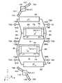
次に、図13ないし図15は第6の実施の形態を示している。そして、本実施の形態の特徴は、加速度検出用の変位検出部は、第1の振動子が振動したときの静電容量の変化を相殺する構成としたことにある。なお、本実施の形態では前記第5の実施の形態と同一の構成要素に同一の符号を付し、その説明を省略するものとする。 Next, FIGS. 13 to 15 show a sixth embodiment. The feature of the present embodiment is that the displacement detection unit for detecting acceleration cancels the change in capacitance when the first vibrator vibrates. In the present embodiment, the same components as those in the fifth embodiment are denoted by the same reference numerals, and the description thereof is omitted.
複合センサ141は、基板72、支持部73,98,101、質量部74,78,82,83,99,102、支持梁77,81,84,100,103、振動発生部86,89、変位検出部92,95,142,145、振動モニタ部110,113等によって構成されている。 The
第1の加速度検出用の変位検出部142(加速度検出用の変位検出手段)は、第1の外側質量部82と第1の非連結質量部99との間に設けられ、非連結質量部99がY軸方向に向けて変位するときの変位量を検出する。ここで、変位検出部142は、図14に示すように、外側質量部82に設けられた検出電極143と、非連結質量部99に設けられた検出電極144とによって構成されている。 The first acceleration detection displacement detection unit 142 (acceleration detection displacement detection means) is provided between the first
また、検出電極143は、例えばT字状に形成された腕部143Aと、外側質量部82に設けられた複数個の第1電極部143Bと、腕部143Aに設けられた複数個の第2電極部143Cとによって構成されている。このとき、腕部143Aは、その基端側が外側質量部82に接続されると共に、その先端側が枠状をなす非連結質量部99の内部に挿入されている。 The
また、各第1電極部143Bは、非連結質量部99に接続された後述の腕部144Aに向けて突出した突起状に形成され、例えば図13中のb2方向に向けて突出している。さらに、各第2電極部143Cは、非連結質量部99に接続された腕部144Aに向けて突出した突起状に形成され、第1電極部143Bとは逆方向となる図13中のb1方向に向けて突出している。そして、第1電極部143Bの個数と第2電極部143Cの個数は、例えば同じ値に設定されている。 Each
一方、検出電極144は、外側質量部82と腕部143Aとの間に挿入された腕部144Aと、腕部144Aのうち外側質量部82と対面する部位に設けられた複数個の第1電極部144Bと、腕部144Aのうち検出電極143の腕部143Aと対面する部位に設けられた複数個の第2電極部144Cとによって構成されている。このとき、各第1電極部144Bは、検出電極143の第1電極部143Bと対応した位置に配置されている。 On the other hand, the
また、各第1電極部144Bは、外側質量部82に向けて突出した突起状に形成され、例えばY軸方向のうち図13中のb1方向に向けて突出している。さらに、各第2電極部144Cは、検出電極143の腕部143Aに向けて突出した突起状に形成され、例えばY軸方向のうち図13中のb2方向に向けて突出している。そして、第1電極部143B,144Bは、Y軸方向の隙間をもって互いに対向し、平行平板コンデンサを形成している。同様に、第2電極部143C,144Cは、Y軸方向の隙間をもって互いに対向し、平行平板コンデンサを形成している。 Each first electrode portion 144B is formed in a protruding shape that protrudes toward the
また、第1電極部143B,144Bは、第1の外側質量部82が中立状態となったときに、例えば突出端面のうち半分程度が部分的に対向するように、X軸方向に位置ずれして配置されている。このとき、第1電極部143Bは、第1電極部144Bに対して例えばX軸方向のうちa1方向に位置ずれして配置されている。 Further, the
一方、第2電極部143C,144Cも、第1電極部143B,144Bと同様に、第1の外側質量部82が中立状態となったときに、例えば突出端面のうち半分程度が部分的に対向するように、X軸方向に位置ずれして配置されている。但し、第2電極部143Cは、第2電極部144Cに対して第1電極部143Bとは逆方向となるa2方向に位置ずれして配置されている。また、加速度αが作用せずに非連結質量部99が停止したときには、第1電極部143B,144B間の距離寸法は、第2電極部143C,144C間の距離寸法とほぼ一致するように設定されている。 On the other hand, as with the
また、検出電極143は外側質量部82と一緒にX軸方向に変位する。これにより、外側質量部82がX軸方向に変位したときには、第1電極部143B,144Bの対向面積が変化すると共に、第2電極部143C,144Cの対向面積が変化する。そして、第1電極部143B,144Bと第2電極部143C,144Cとは、X軸方向で互いに逆方向に位置ずれして配置されている。このため、第1電極部143B,144Bの対向面積が増加するときには、第2電極部143C,144Cの対向面積が減少する。一方、第1電極部143B,144Bの対向面積が減少するときには、第2電極部143C,144Cの対向面積が増加する。 Further, the
この結果、加速度が作用せず非連結質量部99が停止したときには、第1電極部143B,144Bの静電容量と第2電極部143C,144Cの静電容量とは、互いに逆位相で変化する。即ち、第1電極部143B,144Bの静電容量の変化は、第2電極部143C,144Cの静電容量の変化によって相殺される。このため、非連結質量部99が停止したときには、第1電極部143B,144Bの静電容量と第2電極部143C,144Cの静電容量との総和である検出電極143,144間の静電容量Ca1の変化量は、図15中に実線で示すように、変化せずにほぼ一定の値となる。 As a result, when the acceleration does not act and the
一方、非連結質量部99が加速度によってY軸方向に変位したときには、第1電極部143B,144B間の距離寸法と第2電極部143C,144C間の距離寸法とは、互いに逆方向に変化する。即ち、第1電極部143B,144B間の距離寸法が増加するときには、第2電極部143C,144C間の距離寸法が減少する。一方、第1電極部143B,144B間の距離寸法が減少するときには、第2電極部143C,144C間の距離寸法が増加する。そして、第1電極部143B,144Bの静電容量と第2電極部143C,144Cの静電容量とは互いに逆位相で変化するから、検出電極143,144間の静電容量Ca1は、第1電極部143B,144Bの静電容量と第2電極部143C,144Cの静電容量との差に応じて変化する。この結果、非連結質量部99が加速度αによってY軸方向(b1方向,b2方向)に変位したときには、図15中に一点鎖線および破線で示すように、検出電極143,144間の静電容量Ca1は、外側質量部82の振動周期(駆動周期)と一致して変化すると共に、その振幅が非連結質量部99の変位量に応じた値となる。このため、変位検出部142は、検出電極143,144間の静電容量Ca1を用いて、非連結質量部99がY軸方向に変位するときの変位量を検出する。 On the other hand, when the unconnected
第2の加速度検出用の変位検出部145(加速度検出用の変位検出手段)は、第2の外側質量部83と第2の非連結質量部102との間に設けられ、非連結質量部102がY軸方向に向けて変位するときの変位量を検出する。ここで、変位検出部145は、変位検出部142をほぼ同様に、外側質量部83に設けられた検出電極146と、非連結質量部102に設けられた検出電極147とによって構成されている(図13参照)。 The second acceleration detection displacement detector 145 (acceleration detection displacement detector) is provided between the second
また、検出電極146は、例えばT字状に形成された腕部146Aと、外側質量部83に設けられた複数個の第1電極部146Bと、腕部146Aに設けられた複数個の第2電極部146Cとによって構成されている。このとき、腕部146Aは、その基端側が外側質量部83に接続されると共に、その先端側が枠状をなす非連結質量部102の内部に挿入されている。 The detection electrode 146 includes, for example, an
また、各第1電極部146Bは、非連結質量部102に接続された後述の腕部147Aに向けて突出した突起状に形成され、例えば図13中のb1方向に向けて突出している。さらに、各第2電極部146Cは、非連結質量部102に接続された腕部147Aに向けて突出した突起状に形成され、第1電極部146Bとは逆方向となる図13中のb2方向に向けて突出している。そして、第1電極部146Bの個数と第2電極部146Cの個数は、例えば同じ値に設定されている。 Each
一方、検出電極147は、外側質量部83と腕部146Aとの間に挿入された腕部147Aと、腕部147Aのうち外側質量部83と対面する部位に設けられた複数個の第1電極部147Bと、腕部147Aのうち検出電極146の腕部146Aと対面する部位に設けられた複数個の第2電極部147Cとによって構成されている。このとき、各第1電極部147Bは、検出電極146の第1電極部146Bと対応した位置に配置されている。 On the other hand, the
また、各第1電極部147Bは、外側質量部83に向けて突出した突起状に形成され、例えばY軸方向のうち図13中のb2方向に向けて突出している。さらに、各第2電極部147Cは、検出電極146の腕部146Aに向けて突出した突起状に形成され、例えばY軸方向のうち図13中のb1方向に向けて突出している。そして、第1電極部146B,147Bは、Y軸方向の隙間をもって互いに対向し、平行平板コンデンサを形成している。同様に、第2電極部146C,147Cは、Y軸方向の隙間をもって互いに対向し、平行平板コンデンサを形成している。 Each
また、第1電極部146B,147Bは、第2の外側質量部83が中立状態となったときに、例えば突出端面のうち半分程度が部分的に対向するように、X軸方向に位置ずれして配置されている。このとき、第1電極部146Bは、第1電極部147Bに対して例えばX軸方向のうちa2方向に位置ずれして配置されている。 Further, the
一方、第2電極部146C,147Cも、第1電極部146B,147Bと同様に、第2の外側質量部83が中立状態となったときに、例えば突出端面のうち半分程度が部分的に対向するように、X軸方向に位置ずれして配置されている。但し、第2電極部146Cは、第2電極部147Cに対して第1電極部146Bとは逆方向となるa1方向に位置ずれして配置されている。また、加速度が作用せずに非連結質量部102が停止したときには、第1電極部146B,147B間の距離寸法は、第2電極部146C,147C間の距離寸法とほぼ一致するように設定されている。 On the other hand, as with the
そして、第2の変位検出部145も、第1の変位検出部142とほぼ同様に、加速度が作用せず非連結質量部102が停止したときには、検出電極146,147間の静電容量Ca2は、変化せずにほぼ一定の値となる。一方、非連結質量部102が加速度によってY軸方向に変位したときには、検出電極146,147間の静電容量Ca2は、外側質量部83の振動周期(駆動周期)と一致して変化すると共に、その振幅が非連結質量部102の変位量に応じた値となる。さらに、第1の変位検出部142と第2の変位検出部145とは、非連結質量部99,102が加速度によってY軸方向に沿って同じ方向に変位したときには、互いに逆位相の信号を出力する構成となっている。 The second
かくして、このように構成される本実施の形態でも、前記第1,第5の実施の形態とほぼ同様の作用効果を得ることができる。特に、本実施の形態では、加速度検出用の第1の変位検出部142は、第1電極部143B,144Bおよび第2電極部143C,144Cを備える構成とし、第1電極部143B,144Bと第2電極部143C,144Cとは、外側質量部83が変位したときに静電容量の増加と減少が互いに逆に変化し、かつ非連結質量部99が変位したときに静電容量の増加と減少が互いに逆に変化する構成とした。また、第2の変位検出部145も、第1の変位検出部142と同様に構成した。 Thus, also in the present embodiment configured as described above, it is possible to obtain substantially the same operational effects as those of the first and fifth embodiments. In particular, in the present embodiment, the first
これにより、例えば第1の変位検出部142では、加速度が作用せずに非連結質量部102が停止したときには、検出電極143,144間の静電容量Ca1は、変化せずにほぼ一定の値となる。一方、非連結質量部99が加速度によってY軸方向に変位したときには、検出電極143,144間の静電容量Ca1は、外側質量部82の振動周期と一致して変化すると共に、その振幅が非連結質量部99の変位量に応じた値となる。また、第2の変位検出部145も、第1の変位検出部142と同様の出力を得ることができる。 Thereby, for example, in the first
ここで、変位検出部142,145の出力から外側質量部82,83と同一周期の信号を同期検波したときには、同期検波後の加速度信号に対して外側質量部82,83の振動に基づくオフセット成分が含まれる。しかし、本実施の形態では、この加速度信号に含まれるオフセット成分を低減することができるから、信号処理が容易になると共に、オフセット成分に対する加速度成分の割合を高めることができ、加速度の検出精度を高めることができる。 Here, when a signal having the same period as that of the
また、腕部144A,147Aを挟んでY軸方向の両側には第1電極部143B,144B,146B,147Bおよび第2電極部143C,144C,146C,147Cをそれぞれ設ける構成とした。このため、例えば第1電極部143B,144B,146B,147Bおよび第2電極部143C,144C,146C,147Cのうちいずれか一方だけを設けたときに比べて、検出電極143,144,146,147間の静電容量Ca1,Ca2は、2倍の振幅で変化するから、加速度の検出感度を高めることができる。また、単位面積当りの第1電極部143B,144B,146B,147Bおよび第2電極部143C,144C,146C,147Cの個数を2倍以上にすることができるから、同一感度の場合には、素子の小型化が可能となる。 Further, the
さらに、検出電極143,144,146,147間の静電容量Ca1,Ca2を検出するときには、検出電極143,144,146,147間に検出用の電圧を印加する必要があり、この電圧によって検出電極143,144,146,147間に静電力が作用する。このため、この静電力によって非連結質量部99,102が変位して、加速度の検出精度が低下する可能性がある。 Further, when detecting the capacitances Ca1 and Ca2 between the
これに対し、本実施の形態では、腕部144A,147Aを挟んでY軸方向の両側には第1電極部143B,144B,146B,147Bおよび第2電極部143C,144C,146C,147Cをそれぞれ設ける構成としたから、静電容量Ca1,Ca2の検出に伴って電圧を印加しても、この電圧による静電力を相殺することができる。この結果、静電力に伴って加速度の検出特性が劣化するのを低減することができる。 On the other hand, in the present embodiment, the
次に、図16ないし図19は第7の実施の形態を示している。そして、本実施の形態の特徴は、第2,第3の振動子を互いに異なる方向で、かつX軸およびY軸に傾斜した方向に向けて変位可能に設け、これらの第2,第3の振動子を用いてX軸方向およびY軸方向の加速度を検出する構成としたことにある。なお、本実施の形態では前記第5の実施の形態と同一の構成要素に同一の符号を付し、その説明を省略するものとする。 Next, FIGS. 16 to 19 show a seventh embodiment. The feature of the present embodiment is that the second and third vibrators are provided so as to be displaceable in directions different from each other and in a direction inclined to the X axis and the Y axis. The present invention is configured to detect the acceleration in the X-axis direction and the Y-axis direction using a vibrator. In the present embodiment, the same components as those in the fifth embodiment are denoted by the same reference numerals, and the description thereof is omitted.
複合センサ151は、基板72、支持部73,152,155、質量部74,78,82,83,153,156、支持梁77,81,84,154,157、振動発生部86,89、変位検出部92,95,158,161、振動モニタ部110,113等によって構成されている。 The
第1の外側支持部152は、第2の支持部を構成し、質量部全体の重心Gを中心としたときに第1の外側質量部152よりもY軸方向の外側に配置され、基板72の表面に例えば2個設けられている。そして、これら2個の外側支持部152は、後述する非連結質量部153を挟んでX軸およびY軸に対して斜め45°傾斜したc1方向と直交する方向の両側に配置されている。 The first
第1の非連結質量部153は、第2の振動子を構成し、外側質量部82の近傍に位置して基板72の表面側に設けられ、基板72と隙間をもって対向している。また、第1の非連結質量部153は、例えばC字状の枠体によって形成されている。 The first
第1の外側支持梁154は、第2の支持梁を構成し、非連結質量部153と外側支持部152とを接続し、X軸およびY軸に対して斜め45°傾斜したc1方向に向けて振動可能な状態で非連結質量部153を支持している。具体的には、外側支持梁154は、c1方向と直交したc2方向に向けて延び、c1方向に撓み変形可能なばね性を有している。これにより、外側支持梁154は、非連結質量部153をc1方向に振動可能に支持し、非連結質量部153がc2方向に変位するのを規制している。 The first
また、第1の外側支持部152、第1の非連結質量部153、第1の外側支持梁154に対して質量部74,78,82,83を挟んでY軸方向の反対側の位置には、第2の外側支持部155、第2の非連結質量部156、第2の外側支持梁157が設けられている。このとき、第2の外側支持部155、第2の非連結質量部156、第2の外側支持梁157は、第1の外側支持部152、第1の非連結質量部153、第1の外側支持梁154とほぼ同様に形成され、第3の支持部、第3の振動子、第3の支持梁をそれぞれ構成している。 Further, the first
そして、外側支持梁157は、c2方向と直交した方向(c1方向)に向けて延び、c2方向に撓み変形可能なばね性を有している。これにより、外側支持梁157は、非連結質量部153の振動方向(c1方向)と直交するc2方向に振動可能な状態で非連結質量部156を支持し、非連結質量部156がc1方向に変位するのを規制している。 The
また、非連結質量部153,156は、外側質量部82,83に対してY軸方向の反対側の位置に配置されている。このため、Y軸方向に加速度α1が作用したときには、非連結質量部153,156は外側質量部82,83に対して互いに逆方向に変位する。即ち、非連結質量部153が外側質量部82に接近するときには、非連結質量部156は外側質量部83から離れる。また、非連結質量部153が外側質量部82から離れるときには、非連結質量部156は外側質量部83に接近する(図18参照)。 Further, the unconnected
一方、X軸方向に加速度α2が作用したときには、非連結質量部153,156は外側質量部82,83に対して互いに同じ方向に変位する。即ち、非連結質量部153が外側質量部82に接近するときには、非連結質量部156は外側質量部83に接近する。また、非連結質量部153が外側質量部82から離れるときには、非連結質量部156は外側質量部83から離れる(図19参照)。 On the other hand, when the acceleration α2 is applied in the X-axis direction, the
第1の加速度検出用の変位検出部158(加速度検出用の変位検出手段)は、第1の外側質量部82と第1の非連結質量部153との間に設けられ、非連結質量部153がY軸方向に向けて変位するときの変位量を検出する。ここで、変位検出部158は、例えば第6の実施の形態による変位検出部142とほぼ同様に構成され、外側質量部82に設けられた検出電極159と、非連結質量部153に設けられた検出電極160とによって構成されている。このため、検出電極159は、腕部159A、第1電極部159Bおよび第2電極部159Cを備えている。また、検出電極160は、腕部160A、第1電極部160Bおよび第2電極部160Cを備えている。そして、第1電極部159B,160Bは互いに対向して平行平板コンデンサを構成すると共に、第2電極部159C,160Cも互いに対向して平行平板コンデンサを構成している。 The first acceleration detection displacement detection unit 158 (acceleration detection displacement detection means) is provided between the first
第2の加速度検出用の変位検出部161(他の加速度検出用の変位検出手段)は、第2の外側質量部83と第2の非連結質量部156との間に設けられ、非連結質量部156がY軸方向に向けて変位するときの変位量を検出する。ここで、変位検出部161は、例えば第6の実施の形態による変位検出部145とほぼ同様に構成され、外側質量部83に設けられた検出電極162と、非連結質量部156に設けられた検出電極163とによって構成されている。このため、検出電極162は、腕部162A、第1電極部162Bおよび第2電極部162Cを備えている。また、検出電極163は、腕部163A、第1電極部163Bおよび第2電極部163Cを備えている。そして、第1電極部162B,163Bは互いに対向して平行平板コンデンサを構成すると共に、第2電極部162C,163Cも互いに対向して平行平板コンデンサを構成している。 The second acceleration detection displacement detector 161 (another acceleration detection displacement detection means) is provided between the second
次に、加速度α1,α2を検出する加速度検出回路164(加速度検出手段)について説明する。加速度検出回路164は、変位検出部158,161による変位検出信号Vay,Vaxを振動モニタ部110,113によるモニタ信号Vmを用いて同期検波し、質量部153,156に作用する加速度α1,α2を検出する。そして、加速度検出回路164は、例えばC−V変換回路165,166、差動増幅器167、加算増幅器171、同期検波回路168,172等によって構成されている。 Next, the acceleration detection circuit 164 (acceleration detection means) that detects the accelerations α1 and α2 will be described. The
C−V変換回路165,166は変位検出部158,161の出力側にそれぞれ接続されている。そして、C−V変換回路165,166は、変位検出部158,161の静電容量Ca1,Ca2の変化を電圧変化に変換し、これらの電圧変化を予備的な変位検出信号Va1,Va2としてそれぞれ出力する。また、C−V変換回路165,166の出力側には、差動増幅器167および加算増幅器171が並列に接続されている。 The
ここで、Y軸方向に加速度α1が作用したときには、非連結質量部153,156は外側質量部82,83に対して互いに逆方向に変位する(図18参照)。このとき、2つの予備的な変位検出信号Va1,Va2は互いに逆位相となる。このため、2つの予備的な変位検出信号Va1,Va2は差動増幅器167によって差動増幅され、最終的な変位検出信号Vayとして同期検波回路168に出力される。 Here, when the acceleration α1 is applied in the Y-axis direction, the
同期検波回路168の入力側は、差動増幅器167に接続されると共に、AGC回路120に接続されている。また、同期検波回路168の出力側には、加速度信号を取り出すための低域通過フィルタ(LPF)169が接続されると共に、LPF169の出力側にはゲインおよびオフセットを調整するための調整回路170が接続されている。このとき、加速度α1によって非連結質量部153,156が変位すると、この非連結質量部153,156の変位量に応じて変位検出部158,161の静電容量Ca1,Ca2は、質量部74,78,82,83のX軸方向の振動と同期して変化する。このため、同期検波回路168は、変位検出信号Vayからモニタ信号Vmを用いて同期検波し、LPF169、調整回路170を介してY軸方向の加速度α1に応じた加速度信号を出力する。 The input side of the
一方、X軸方向に加速度α2が作用したときには、非連結質量部153,156は外側質量部82,83に対して互いに同じ方向に変位する(図19参照)。このとき、2つの予備的な変位検出信号Va1,Va2は互いに同位相となる。このため、2つの予備的な変位検出信号Va1,Va2は加算増幅器171によって加算増幅され、最終的な変位検出信号Vaxとして同期検波回路172に出力される。 On the other hand, when the acceleration α2 is applied in the X-axis direction, the
同期検波回路172の入力側は、加算増幅器171に接続されると共に、AGC回路120に接続されている。また、同期検波回路172の出力側には、加速度信号を取り出すための低域通過フィルタ(LPF)173が接続されると共に、LPF173の出力側にはゲインおよびオフセットを調整するための調整回路174が接続されている。このとき、加速度α2によって非連結質量部153,156が変位すると、この非連結質量部153,156の変位量に応じて変位検出部158,161の静電容量Ca1,Ca2は、質量部74,78,82,83のX軸方向の振動と同期して変化する。このため、同期検波回路172は、変位検出信号Vaxからモニタ信号Vmを用いて同期検波し、LPF173、調整回路174を介してX軸方向の加速度α2に応じた加速度信号を出力する。 The input side of the
かくして、このように構成される本実施の形態でも、前記第1,第5の実施の形態とほぼ同様の作用効果を得ることができる。特に、本実施の形態では、非連結質量部153,156を互いに異なる方向で、かつX軸およびY軸に傾斜したc1,c2方向に変位可能に設け、変位検出部158,161は非連結質量部153,156のY軸方向の変位量を検出する構成とした。このため、変位検出部158,161による変位検出信号Va1,Va2の差を用いてY軸方向の加速度α1(第1の加速度)を検出することができる。これに加えて、変位検出部158,161による変位検出信号Va1,Va2の和を用いてX軸方向の加速度α2(第2の加速度)を検出することができる。この結果、互いに直交する2軸方向の加速度α1,α2を一緒に検出することができる。 Thus, also in the present embodiment configured as described above, it is possible to obtain substantially the same operational effects as those of the first and fifth embodiments. In particular, in the present embodiment, the unconnected
また、非連結質量部153,156はX軸およびY軸に傾斜したc1,c2方向に変位可能に設けたから、Y軸方向の加速度α1およびX軸方向の加速度α2のいずれが作用したときでも、非連結質量部153,156を変位させることができる。このため、例えばX軸方向に振動する質量部74,78,82,83の近傍にX軸方向に変位する加速度検出用の振動子を配置できないときでも、X軸方向の加速度α2を検出することができる。 Further, since the unconnected
次に、図20および図21は第8の実施の形態を示している。そして、本実施の形態の特徴は、第2,第3の振動子をそれぞれ2個ずつ設け、これら合計4個の第2,第3の振動子を用いてX軸方向およびY軸方向の加速度を検出する構成としたことにある。なお、本実施の形態では前記第5の実施の形態と同一の構成要素に同一の符号を付し、その説明を省略するものとする。 Next, FIG. 20 and FIG. 21 show an eighth embodiment. The feature of the present embodiment is that two each of the second and third vibrators are provided, and the acceleration in the X-axis direction and the Y-axis direction is made using a total of four second and third vibrators. It is in the structure which detects this. In the present embodiment, the same components as those in the fifth embodiment are denoted by the same reference numerals, and the description thereof is omitted.
複合センサ181は、基板72、支持部73,182,185,188,191、質量部74,78,82,83,183,186,189,192、支持梁77,81,84,184,187,190,193、振動発生部86,89、変位検出部92,95,194,197,200,203、振動モニタ部110,113等によって構成されている。 The
第1の外側支持部182は、第2の支持部を構成し、第7の実施の形態による第1の外側支持部152とほぼ同様に構成されている。そして、第1の外側支持部182は、基板72の表面に例えば2個設けられ、後述する非連結質量部183を挟んでX軸およびY軸に対して斜め45°傾斜したc1方向と直交する方向の両側に配置されている。 The 1st outer
第1の非連結質量部183は、第2の振動子を構成し、第7の実施の形態による第1の非連結質量部153とほぼ同様に構成されている。そして、第1の非連結質量部183は、外側質量部82の近傍に配置されている。 The first
第1の外側支持梁184は、第2の支持梁を構成し、第7の実施の形態による第1の外側支持梁154とほぼ同様に構成されている。このため、第1の外側支持梁184は、非連結質量部183をc1方向に振動可能に支持し、非連結質量部183がc2方向に変位するのを規制している。 The first
第2の外側支持部185は、第3の支持部を構成し、第7の実施の形態による第2の外側支持部155とほぼ同様に構成されている。そして、第2の外側支持部185は、基板72の表面に例えば2個設けられ、後述する非連結質量部186を挟んでX軸およびY軸に対して斜め45°傾斜したc2方向と直交する方向の両側に配置されている。 The second
第2の非連結質量部186は、第3の振動子を構成し、第7の実施の形態による第2の非連結質量部156とほぼ同様に構成されている。そして、第2の非連結質量部186は、外側質量部83の近傍に配置されている。 The second
第2の外側支持梁187は、第3の支持梁を構成し、第7の実施の形態による第2の外側支持梁157とほぼ同様に構成されている。このため、第2の外側支持梁187は、非連結質量部186をc2方向に振動可能に支持し、非連結質量部186がc1方向に変位するのを規制している。 The second
第3の外側支持部188、第3の非連結質量部189、第3の外側支持梁190は、質量部全体の重心Gを挟んで第1の外側支持部182、第1の非連結質量部183、第1の外側支持梁184とほぼ対称となる位置に設けられている。そして、第3の外側支持部188、第3の非連結質量部189、第3の外側支持梁190は、第2の支持部、第2の振動子、第2の支持梁をそれぞれ構成している。このため、第3の非連結質量部189は、外側質量部83の近傍に位置して、c1方向に振動可能に設けられている。 The third
第4の外側支持部191、第4の非連結質量部192、第4の外側支持梁193は、質量部全体の重心Gを挟んで第2の外側支持部185、第2の非連結質量部186、第2の外側支持梁187とほぼ対称となる位置に設けられている。そして、第4の外側支持部191、第4の非連結質量部192、第4の外側支持梁193は、第3の支持部、第3の振動子、第3の支持梁をそれぞれ構成している。このため、第4の非連結質量部192は、外側質量部82の近傍に位置して、c2方向に振動可能に設けられている。 The fourth
第1の変位検出部194(加速度検出用の変位検出手段)は、質量部82,183間に設けられ、第7の実施の形態による第1の変位検出部158とほぼ同様に構成されている。このため、第1の変位検出部194は、検出電極195,196を備え、非連結質量部183がY軸方向に変位したときの変位量を検出する。 The first displacement detector 194 (acceleration detection displacement detector) is provided between the
第2の変位検出部197(他の加速度検出用の変位検出手段)は、質量部83,186間に設けられ、第7の実施の形態による第2の変位検出部161とほぼ同様に構成されている。このため、第2の変位検出部197は、検出電極198,199を備え、非連結質量部186がY軸方向に変位したときの変位量を検出する。 The second displacement detection unit 197 (other acceleration detection displacement detection means) is provided between the
第3の変位検出部200(加速度検出用の変位検出手段)は、質量部83,189間に設けられ、第7の実施の形態による第1の変位検出部158とほぼ同様に構成されている。このため、第3の変位検出部200は、検出電極201,202を備え、非連結質量部189がY軸方向に変位したときの変位量を検出する。 The third displacement detection unit 200 (acceleration detection displacement detection means) is provided between the
第4の変位検出部203(他の加速度検出用の変位検出手段)は、質量部82,192間に設けられ、第7の実施の形態による第2の変位検出部161とほぼ同様に構成されている。このため、第4の変位検出部203は、検出電極204,205を備え、非連結質量部192がY軸方向に変位したときの変位量を検出する。 The fourth displacement detection unit 203 (another acceleration detection displacement detection unit) is provided between the
次に、加速度α1,α2を検出する加速度検出回路206(加速度検出手段)について説明する。加速度検出回路206は、変位検出部194,197,200,203による変位検出信号Vay,Vaxを振動モニタ部110,113によるモニタ信号Vmを用いて同期検波し、質量部183,186,189,192に作用する加速度α1,α2を検出する。そして、加速度検出回路206は、例えばC−V変換回路207,208,209,210、加算増幅器211,212,217,218、差動増幅器213,219、同期検波回路214,220等によって構成されている。 Next, the acceleration detection circuit 206 (acceleration detection means) that detects the accelerations α1 and α2 will be described. The
C−V変換回路207,208,209,210は、変位検出部194,197,200,203の静電容量Ca1,Ca2,Ca3,Ca4の変化を電圧変化に変換し、これらの電圧変化を予備的な変位検出信号Va1,Va2,Va3,Va4としてそれぞれ出力する。 The
加算増幅器211は、C−V変換回路207,208の出力側に接続され、これらの予備的な変位検出信号Va1,Va2を加算する。また、加算増幅器212は、C−V変換回路209,210の出力側に接続され、これらの予備的な変位検出信号Va3,Va4を加算する。さらに、差動増幅器213は、加算増幅器211,212の出力の差から最終的な変位検出信号Vayを演算し、同期検波回路214に出力する。これにより、同期検波回路214は、変位検出信号Vayからモニタ信号Vmを用いて同期検波し、LPF215、調整回路216を介してY軸方向の加速度α1に応じた加速度信号を出力する。 The summing
一方、加算増幅器217は、C−V変換回路207,210の出力側に接続され、これらの予備的な変位検出信号Va1,Va4を加算する。また、加算増幅器218は、C−V変換回路208,209の出力側に接続され、これらの予備的な変位検出信号Va2,Va3を加算する。さらに、差動増幅器219は、加算増幅器217,218の出力の差から最終的な変位検出信号Vaxを演算し、同期検波回路220に出力する。これにより、同期検波回路220は、変位検出信号Vaxからモニタ信号Vmを用いて同期検波し、LPF221、調整回路222を介してX軸方向の加速度α2に応じた加速度信号を出力する。 On the other hand, the
かくして、このように構成される本実施の形態でも、前記第1,第5の実施の形態とほぼ同様の作用効果を得ることができる。特に、本実施の形態では、非連結質量部183,189をc1方向に変位可能に設け、非連結質量部186,192をc2方向に変位可能に設け、これら非連結質量部183,186,189,192のY軸方向の変位量を変位検出部194,197,200,203を用いて検出する構成とした。このため、変位検出部194,197,200,203による変位検出信号Va1,Va2,Va3,Va4を加算および減算の演算処理することによって、Y軸方向およびX軸方向の加速度α1,α2を検出することができる。また、変位検出部194,197,200,203による変位検出信号Va1,Va2,Va3,Va4を加算および減算の演算処理を施すから、例えば外気温度等によって変位検出信号Va1,Va2,Va3,Va4が変化するときでも、このような温度変化等の影響を低減することができ、加速度α1,α2の検出精度を高めることができる。 Thus, also in the present embodiment configured as described above, it is possible to obtain substantially the same operational effects as those of the first and fifth embodiments. In particular, in this embodiment, the unconnected
次に、図22は第9の実施の形態を示している。そして、本実施の形態の特徴は、角速度検出に関する構成を省いたことにある。なお、本実施の形態では前記第1の実施の形態と同一の構成要素に同一の符号を付し、その説明を省略するものとする。 Next, FIG. 22 shows a ninth embodiment. The feature of this embodiment is that the configuration relating to angular velocity detection is omitted. In the present embodiment, the same components as those in the first embodiment are denoted by the same reference numerals, and the description thereof is omitted.
加速度センサ231は、基板2、支持部3,14、振動子4,15、支持梁5,16、振動発生部8、変位検出部17、振動モニタ部20等によって構成されている。即ち、本実施の形態では、第1の実施の形態による角速度検出に関する構成(振動子6、支持梁7、変位検出部11等)を省いた構成となっている。 The
かくして、本実施の形態では、角速度の検出はできないものの、第1の実施の形態と同様に、加速度αを高精度に検出することができる。 Thus, although the angular velocity cannot be detected in the present embodiment, the acceleration α can be detected with high accuracy as in the first embodiment.
なお、前記第5および第6の実施の形態では、非連結質量部99,102はY軸方向に変位可能に設ける構成とした。しかし、本発明はこれに限らず、第2の実施の形態と同様に、非連結質量部をX軸方向に変位可能に設ける構成としてもよく、第3の実施の形態と同様に、2つの非連結質量部のうち一方をY軸方向に変位可能に設け、他方をX軸方向に変位可能に設ける構成としてもよい。 In the fifth and sixth embodiments, the
なお、前記第7および第8の実施の形態では、変位検出部158,161,194,197,200,203は、第6の実施の形態による変位検出部142,145と同様に構成するものとしたが、例えば第5の実施の形態による変位検出部104,107と同様に構成してもよい。 In the seventh and eighth embodiments, the
また、前記第5ないし第8の実施の形態では、例えば4個の質量部74,78,82,83を連結支持梁84によって連結する構成とした。しかし、本発明はこれに限らず、例えば3個以下、または5個以上の質量部を連結する構成としてもよい。 In the fifth to eighth embodiments, for example, the four
さらに、前記第5ないし第8の実施の形態では、Z軸周りの角速度Ωを検出する構成とした。しかし、本発明はこれに限らず、第4の実施の形態と同様に、角速度検出用振動子は角速度検出用支持梁によってZ軸方向に変位可能に設け、Y軸周りの角速度Ωを検出する構成としてもよい。 Further, in the fifth to eighth embodiments, the angular velocity Ω around the Z axis is detected. However, the present invention is not limited to this, and similarly to the fourth embodiment, the angular velocity detecting vibrator is provided to be displaceable in the Z-axis direction by the angular velocity detecting support beam, and detects the angular velocity Ω around the Y axis. It is good also as a structure.
Claims (8)
Translated fromJapanese該基板に設けられた第1の支持部と、
前記基板と隙間をもって対向して配置された第1の振動子と、
該第1の振動子と第1の支持部とを接続し、互いに直交するX軸、Y軸、Z軸からなる3軸方向のうちX軸方向に向けて振動可能な状態で該第1の振動子を支持する第1の支持梁と、
前記第1の振動子に設けられた角速度検出用振動子と、
該角速度検出用振動子と第1の振動子とを接続し、該角速度検出用振動子をY軸方向またはZ軸方向に向けて変位可能に支持する角速度検出用支持梁と、
前記第1の振動子をX軸方向に振動させる振動発生手段と、
前記第1の振動子がX軸方向に振動した状態で角速度検出用振動子がY軸方向またはZ軸方向に向けて変位するときの変位量を検出する角速度検出用の変位検出手段と、
前記基板に設けられた第2の支持部と、
前記基板と隙間をもって対向して配置された第2の振動子と、
該第2の振動子と第2の支持部とを接続し、X軸方向またはY軸方向に向けて変位可能な状態で該第2の振動子を支持する第2の支持梁と、
前記第1,第2の振動子の間に設けられ、第2の振動子がX軸方向またはY軸方向に変位するときの変位量を検出する加速度検出用の変位検出手段と、
前記第1の振動子がX軸方向に振動したときの第1の振動子の変位をモニタする振動モニタ手段と、
前記加速度検出用の変位検出手段による変位検出信号を該振動モニタ手段によるモニタ信号を用いて同期検波し、前記第2の振動子に作用する加速度を検出する加速度検出手段とを備える構成としてなる複合センサ。A substrate,
A first support provided on the substrate;
A first vibrator disposed to face the substrate with a gap;
The first vibrator is connected to the first support portion, and the first vibrator is capable of vibrating in the X-axis direction among the three axial directions including the X-axis, Y-axis, and Z-axis that are orthogonal to each other. A first support beam for supporting the vibrator;
An angular velocity detecting vibrator provided in the first vibrator;
An angular velocity detection support beam that connects the angular velocity detection vibrator and the first vibrator, and supports the angular velocity detection vibrator so as to be displaceable in the Y-axis direction or the Z-axis direction;
Vibration generating means for vibrating the first vibrator in the X-axis direction;
Displacement detecting means for detecting angular velocity, which detects a displacement amount when the angular velocity detecting vibrator is displaced in the Y-axis direction or the Z-axis direction in a state where the first vibrator is vibrated in the X-axis direction;
A second support provided on the substrate;
A second vibrator disposed to face the substrate with a gap;
A second support beam connecting the second vibrator and the second support portion and supporting the second vibrator in a state displaceable in the X-axis direction or the Y-axis direction;
A displacement detecting means for detecting an acceleration provided between the first and second vibrators and detecting a displacement amount when the second vibrator is displaced in the X-axis direction or the Y-axis direction;
Vibration monitoring means for monitoring the displacement of the first vibrator when the first vibrator vibrates in the X-axis direction;
A composite comprising: an acceleration detection means for detecting the acceleration acting on the second vibrator by synchronously detecting a displacement detection signal from the acceleration detection displacement detection means using a monitor signal from the vibration monitoring means. Sensor.
該第3の振動子と第3の支持部との間には、X軸方向およびY軸方向のうち前記第2の振動子が変位可能な方向と異なる方向に変位可能な状態で該第3の振動子を支持する第3の支持梁を設け、
前記第1,第3の振動子の間には、第3の振動子がY軸方向またはX軸方向に変位するときの変位量を検出する他の加速度検出用の変位検出手段を設け、
前記他の加速度検出用の変位検出手段による変位検出信号を前記振動モニタ手段によるモニタ信号を用いて同期検波し、前記第3の振動子に作用する加速度を検出する他の加速度検出手段を備える構成としてなる請求項1に記載の複合センサ。The substrate is provided with a third support portion and a third vibrator arranged to face each other with a gap,
Between the third vibrator and the third support portion, the third vibrator can be displaced in a direction different from the direction in which the second vibrator can be displaced in the X-axis direction and the Y-axis direction. Providing a third support beam for supporting the vibrator of
Between the first and third vibrators, there is provided another acceleration detection displacement detecting means for detecting a displacement amount when the third vibrator is displaced in the Y-axis direction or the X-axis direction,
Configuration comprising other acceleration detection means for detecting the acceleration acting on the third vibrator by synchronously detecting a displacement detection signal from the other acceleration detection displacement detection means using the monitor signal from the vibration monitoring means The composite sensor according to claim 1.
前記第1の支持梁は、該複数の第1の振動子を互いに連結し、
前記振動発生手段は、互いに隣合う第1の振動子を逆位相で振動させる構成としてなる請求項1に記載の複合センサ。A plurality of the first vibrators are arranged side by side in the Y-axis direction,
The first support beam connects the plurality of first vibrators to each other,
2. The composite sensor according to claim 1, wherein the vibration generating unit is configured to vibrate the first vibrators adjacent to each other in opposite phases.
前記加速度検出用の変位検出手段は、該2つの第2の振動子に対応して2つ設け、
前記加速度検出手段は、該2つの加速度検出用の変位検出手段による変位検出信号の差を用いて加速度を検出する構成としてなる請求項1または3に記載の複合センサ。Two of the second vibrators are provided so as to be displaced in directions opposite to each other with respect to the first vibrator when acceleration is applied,
Two displacement detection means for detecting the acceleration are provided corresponding to the two second vibrators,
4. The composite sensor according to claim 1, wherein the acceleration detection unit is configured to detect acceleration using a difference between displacement detection signals by the two acceleration detection displacement detection units. 5.
該一対の電極部は、前記第1の振動子が停止した中立状態となるときに、部分的に対向するようにX軸方向に対して互いに位置ずれして配置する構成としてなる請求項1または3に記載の複合センサ。The acceleration detecting displacement detecting means is provided between the first and second vibrators so as to face each other, and a pair of capacitances that change according to the displacement of the first and second vibrators. The electrode part of
The pair of electrode portions are configured so as to be displaced from each other with respect to the X-axis direction so as to partially face each other when the first vibrator is in a neutral state in which the first vibrator is stopped. 3. The composite sensor according to 3.
前記一対の第1電極部と一対の第2電極部とは、前記第1の振動子が変位したときに静電容量の増加と減少が互いに逆に変化し、かつ前記第2の振動子が変位したときに静電容量の増加と減少が互いに逆に変化する構成としてなる請求項1または3に記載の複合センサ。The acceleration detecting displacement detecting means is provided between the first and second vibrators so as to face each other, and a pair of capacitances that change according to the displacement of the first and second vibrators. The first electrode portion and a pair of second electrode portions are provided,
The pair of first electrode portions and the pair of second electrode portions are configured such that when the first vibrator is displaced, an increase and a decrease in capacitance are changed in reverse to each other, and the second vibrator is The composite sensor according to claim 1, wherein when the sensor is displaced, the increase and decrease in capacitance change in opposite directions.
該基板に設けられた第1の支持部と、
前記基板と隙間をもって対向して配置された第1の振動子と、
該第1の振動子と第1の支持部とを接続し、互いに直交するX軸、Y軸、Z軸からなる3軸方向のうちX軸方向に向けて振動可能な状態で該第1の振動子を支持する第1の支持梁と、
前記第1の振動子に設けられた角速度検出用振動子と、
該角速度検出用振動子と第1の振動子とを接続し、該角速度検出用振動子をY軸方向またはZ軸方向に向けて変位可能に支持する角速度検出用支持梁と、
前記第1の振動子をX軸方向に振動させる振動発生手段と、
前記第1の振動子がX軸方向に振動した状態で角速度検出用振動子がY軸方向またはZ軸方向に向けて変位するときの変位量を検出する角速度検出用の変位検出手段と、
前記基板に設けられた第2の支持部と、
前記基板と隙間をもって対向して配置された第2の振動子と、
該第2の振動子と第2の支持部とを接続し、Z軸と直交し、かつX軸およびY軸に対して傾斜した傾斜方向に向けて変位可能な状態で該第2の振動子を支持する第2の支持梁と、
前記第1,第2の振動子の間に設けられ、第2の振動子がY軸方向に変位するときの変位量を検出する加速度検出用の変位検出手段と、
前記基板に設けられた第3の支持部と、
前記基板と隙間をもって対向して配置された第3の振動子と、
該第3の振動子と第3の支持部とを接続し、Z軸と直交し、かつX軸およびY軸に対して傾斜した傾斜方向であって前記第2の振動子が変位する方向と異なる方向に向けて変位可能な状態で該第3の振動子を支持する第3の支持梁と、
前記第1,第3の振動子の間に設けられ、第3の振動子がY軸方向に変位するときの変位量を検出する他の加速度検出用の変位検出手段と、
前記第1の振動子がX軸方向に振動したときの第1の振動子の変位をモニタする振動モニタ手段と、
前記2つの加速度検出用の変位検出手段による変位検出信号の差を該振動モニタ手段によるモニタ信号を用いて同期検波して第1の加速度を検出し、前記2つの加速度検出用の変位検出手段による変位検出信号の和を該振動モニタ手段によるモニタ信号を用いて同期検波して第2の加速度を検出する加速度検出手段とを備える構成としてなる複合センサ。A substrate,
A first support provided on the substrate;
A first vibrator disposed to face the substrate with a gap;
The first vibrator is connected to the first support portion, and the first vibrator is capable of vibrating in the X-axis direction among the three axial directions including the X-axis, Y-axis, and Z-axis that are orthogonal to each other. A first support beam for supporting the vibrator;
An angular velocity detecting vibrator provided in the first vibrator;
An angular velocity detection support beam that connects the angular velocity detection vibrator and the first vibrator, and supports the angular velocity detection vibrator so as to be displaceable in the Y-axis direction or the Z-axis direction;
Vibration generating means for vibrating the first vibrator in the X-axis direction;
Displacement detecting means for detecting angular velocity, which detects a displacement amount when the angular velocity detecting vibrator is displaced in the Y-axis direction or the Z-axis direction in a state where the first vibrator is vibrated in the X-axis direction;
A second support provided on the substrate;
A second vibrator disposed to face the substrate with a gap;
The second vibrator is connected to the second vibrator and the second support portion, and is displaceable in an inclined direction that is orthogonal to the Z axis and inclined with respect to the X axis and the Y axis. A second support beam for supporting
A displacement detecting means for detecting acceleration, which is provided between the first and second vibrators and detects a displacement amount when the second vibrator is displaced in the Y-axis direction;
A third support provided on the substrate;
A third vibrator disposed facing the substrate with a gap;
An inclination direction that connects the third vibrator and the third support, is orthogonal to the Z axis, and is inclined with respect to the X axis and the Y axis, and the direction in which the second vibrator is displaced, A third support beam that supports the third vibrator in a state displaceable in different directions;
Displacement detecting means for detecting other acceleration provided between the first and third vibrators and detecting a displacement amount when the third vibrator is displaced in the Y-axis direction;
Vibration monitoring means for monitoring the displacement of the first vibrator when the first vibrator vibrates in the X-axis direction;
A difference between displacement detection signals by the two acceleration detection displacement detection means is synchronously detected using a monitor signal by the vibration monitoring means to detect a first acceleration, and by the two acceleration detection displacement detection means. A composite sensor comprising: an acceleration detection means for detecting a second acceleration by synchronously detecting a sum of displacement detection signals using a monitor signal from the vibration monitoring means.
該基板に設けられた第1の支持部と、
前記基板と隙間をもって対向して配置された第1の振動子と、
該第1の振動子と第1の支持部とを接続し、互いに直交するX軸、Y軸、Z軸からなる3軸方向のうちX軸方向に向けて振動可能な状態で該第1の振動子を支持する第1の支持梁と、
前記第1の振動子をX軸方向に振動させる振動発生手段と、
前記基板に設けられた第2の支持部と、
前記基板と隙間をもって対向して配置された第2の振動子と、
該第2の振動子と第2の支持部とを接続し、X軸方向またはY軸方向に向けて変位可能な状態で該第2の振動子を支持する第2の支持梁と、
前記第1,第2の振動子の間に設けられ、第2の振動子がX軸方向またはY軸方向に変位するときの変位量を検出する加速度検出用の変位検出手段と、
前記第1の振動子がX軸方向に振動したときの第1の振動子の変位をモニタする振動モニタ手段と、
前記加速度検出用の変位検出手段による変位検出信号を該振動モニタ手段によるモニタ信号を用いて同期検波し、前記第2の振動子に作用する加速度を検出する加速度検出手段とを備える構成としてなる加速度センサ。A substrate,
A first support provided on the substrate;
A first vibrator disposed to face the substrate with a gap;
The first vibrator is connected to the first support portion, and the first vibrator is capable of vibrating in the X-axis direction among the three axial directions including the X-axis, Y-axis, and Z-axis that are orthogonal to each other. A first support beam for supporting the vibrator;
Vibration generating means for vibrating the first vibrator in the X-axis direction;
A second support provided on the substrate;
A second vibrator disposed to face the substrate with a gap;
A second support beam connecting the second vibrator and the second support portion and supporting the second vibrator in a state displaceable in the X-axis direction or the Y-axis direction;
A displacement detecting means for detecting an acceleration provided between the first and second vibrators and detecting a displacement amount when the second vibrator is displaced in the X-axis direction or the Y-axis direction;
Vibration monitoring means for monitoring the displacement of the first vibrator when the first vibrator vibrates in the X-axis direction;
Acceleration comprising: an acceleration detection means for detecting the acceleration acting on the second vibrator by synchronously detecting a displacement detection signal from the acceleration detection displacement detection means using a monitor signal from the vibration monitoring means. Sensor.
Applications Claiming Priority (1)
| Application Number | Priority Date | Filing Date | Title |
|---|---|---|---|
| PCT/JP2007/068174WO2009037751A1 (en) | 2007-09-19 | 2007-09-19 | Composite sensor and acceleration sensor |
Publications (2)
| Publication Number | Publication Date |
|---|---|
| JPWO2009037751A1 JPWO2009037751A1 (en) | 2011-01-06 |
| JP4687791B2true JP4687791B2 (en) | 2011-05-25 |
Family
ID=40453065
Family Applications (1)
| Application Number | Title | Priority Date | Filing Date |
|---|---|---|---|
| JP2008528268AExpired - Fee RelatedJP4687791B2 (en) | 2007-09-19 | 2007-09-19 | Composite sensor and acceleration sensor |
Country Status (6)
| Country | Link |
|---|---|
| US (1) | US7677100B2 (en) |
| EP (1) | EP2075534A4 (en) |
| JP (1) | JP4687791B2 (en) |
| KR (1) | KR100992250B1 (en) |
| CN (1) | CN101563582B (en) |
| WO (1) | WO2009037751A1 (en) |
Families Citing this family (34)
| Publication number | Priority date | Publication date | Assignee | Title |
|---|---|---|---|---|
| US8508039B1 (en) | 2008-05-08 | 2013-08-13 | Invensense, Inc. | Wafer scale chip scale packaging of vertically integrated MEMS sensors with electronics |
| US20090262074A1 (en)* | 2007-01-05 | 2009-10-22 | Invensense Inc. | Controlling and accessing content using motion processing on mobile devices |
| US20100071467A1 (en)* | 2008-09-24 | 2010-03-25 | Invensense | Integrated multiaxis motion sensor |
| US7934423B2 (en) | 2007-12-10 | 2011-05-03 | Invensense, Inc. | Vertically integrated 3-axis MEMS angular accelerometer with integrated electronics |
| US20090265671A1 (en)* | 2008-04-21 | 2009-10-22 | Invensense | Mobile devices with motion gesture recognition |
| US8020441B2 (en)* | 2008-02-05 | 2011-09-20 | Invensense, Inc. | Dual mode sensing for vibratory gyroscope |
| US8462109B2 (en) | 2007-01-05 | 2013-06-11 | Invensense, Inc. | Controlling and accessing content using motion processing on mobile devices |
| US8047075B2 (en)* | 2007-06-21 | 2011-11-01 | Invensense, Inc. | Vertically integrated 3-axis MEMS accelerometer with electronics |
| US8141424B2 (en)* | 2008-09-12 | 2012-03-27 | Invensense, Inc. | Low inertia frame for detecting coriolis acceleration |
| US8952832B2 (en)* | 2008-01-18 | 2015-02-10 | Invensense, Inc. | Interfacing application programs and motion sensors of a device |
| US8250921B2 (en)* | 2007-07-06 | 2012-08-28 | Invensense, Inc. | Integrated motion processing unit (MPU) with MEMS inertial sensing and embedded digital electronics |
| JP4868027B2 (en) | 2009-05-26 | 2012-02-01 | 株式会社デンソー | Acceleration angular velocity sensor |
| US20120227491A1 (en)* | 2009-12-17 | 2012-09-13 | Toyota Jidosha Kabushiki Kaisha | Angular velocity detecting apparatus |
| WO2011102063A1 (en)* | 2010-02-17 | 2011-08-25 | 株式会社村田製作所 | Oscillation-type inertial force sensor |
| CN102753936B (en)* | 2010-02-17 | 2015-11-25 | 株式会社村田制作所 | Vibration Type Inertial Force Sensor |
| JP5341807B2 (en)* | 2010-03-26 | 2013-11-13 | 株式会社東芝 | Acceleration sensor |
| DE102010029565A1 (en)* | 2010-06-01 | 2011-12-01 | Robert Bosch Gmbh | Method for operating a sensor arrangement and sensor arrangement |
| DE102010029590B4 (en)* | 2010-06-01 | 2014-07-10 | Robert Bosch Gmbh | Rotation rate sensor, sensor arrangement, method for operating a rotation rate sensor and method for operating a sensor arrangement |
| DE102010062581A1 (en)* | 2010-12-08 | 2012-06-14 | Robert Bosch Gmbh | Rotation rate sensor, sensor system, method for operating a rotation rate sensor and method for operating a sensor system |
| US9715480B1 (en) | 2011-06-24 | 2017-07-25 | United States Of America As Represented By Secretary Of The Navy | Method for analytical reconstruction of digital signals via stitched polynomial fitting |
| US9705450B2 (en) | 2011-06-24 | 2017-07-11 | The United States Of America As Represented By The Secretary Of The Navy | Apparatus and methods for time domain measurement of oscillation perturbations |
| DE102011083487B4 (en)* | 2011-09-27 | 2023-12-21 | Robert Bosch Gmbh | Acceleration sensor and method for operating an acceleration sensor |
| US8875576B2 (en)* | 2012-03-21 | 2014-11-04 | The United States Of America As Represented By The Secretary Of The Navy | Apparatus and method for providing an in-plane inertial device with integrated clock |
| JP6098780B2 (en)* | 2012-04-19 | 2017-03-22 | セイコーエプソン株式会社 | Gyro sensor and electronics |
| JP6061064B2 (en)* | 2012-05-14 | 2017-01-18 | セイコーエプソン株式会社 | Gyro sensor and electronic equipment |
| KR20150015932A (en)* | 2013-08-02 | 2015-02-11 | 삼성전기주식회사 | Apparatus and Method for driving gyro sensor |
| KR101671856B1 (en) | 2015-07-14 | 2016-11-03 | 곽상천 | The method and apparatus for providing tourist information based on application |
| JP6512006B2 (en)* | 2015-07-14 | 2019-05-15 | 株式会社デンソー | Sensor device |
| JP6733333B2 (en)* | 2015-08-26 | 2020-07-29 | セイコーエプソン株式会社 | Physical quantity detection device, physical quantity detection device manufacturing method, electronic apparatus, and moving body |
| US11428705B2 (en)* | 2017-04-17 | 2022-08-30 | Panasonic Intellectual Property Management Co., Ltd. | Angular velocity sensor and angular velocity sensor control method |
| DE102018211755A1 (en)* | 2018-07-13 | 2020-01-16 | Infineon Technologies Ag | AMPLITUDE DETECTION, AMPLITUDE CONTROL AND DIRECTION DETECTION OF A VIBRATION OF A VIBRATION BODY |
| JP7128697B2 (en)* | 2018-09-19 | 2022-08-31 | ファスフォードテクノロジ株式会社 | Die bonding apparatus and semiconductor device manufacturing method |
| DE102020112261A1 (en) | 2020-05-06 | 2021-11-11 | Northrop Grumman Litef Gmbh | Coupling device for coupling vibration systems |
| JP7622971B2 (en)* | 2020-06-17 | 2025-01-28 | 特許機器株式会社 | Servo type vibration detector and vibration control device |
Citations (5)
| Publication number | Priority date | Publication date | Assignee | Title |
|---|---|---|---|---|
| JPH1164370A (en)* | 1997-08-26 | 1999-03-05 | Japan Aviation Electron Ind Ltd | Multi-axis inertial sensor |
| JP2000028365A (en)* | 1998-07-10 | 2000-01-28 | Murata Mfg Co Ltd | Angular velocity sensor |
| JP2002005950A (en)* | 2000-06-23 | 2002-01-09 | Murata Mfg Co Ltd | Combined sensor element and its manufacturing method |
| JP2004132988A (en)* | 2002-10-12 | 2004-04-30 | Samsung Electro Mech Co Ltd | Microgyroscope for preventing signal detection by translational acceleration |
| JP2005283424A (en)* | 2004-03-30 | 2005-10-13 | Denso Corp | Dynamic quantity sensor unit |
Family Cites Families (6)
| Publication number | Priority date | Publication date | Assignee | Title |
|---|---|---|---|---|
| JPH10239347A (en)* | 1997-02-28 | 1998-09-11 | Japan Aviation Electron Ind Ltd | Motion sensor |
| DE19719780B4 (en)* | 1997-05-10 | 2006-09-07 | Robert Bosch Gmbh | Acceleration detecting means |
| JP2003028644A (en)* | 2001-07-12 | 2003-01-29 | Denso Corp | Angular velocity sensor |
| JP3870895B2 (en)* | 2002-01-10 | 2007-01-24 | 株式会社村田製作所 | Angular velocity sensor |
| JP4645013B2 (en)* | 2003-10-03 | 2011-03-09 | パナソニック株式会社 | Acceleration sensor and composite sensor using the same |
| JP2006105698A (en)* | 2004-10-01 | 2006-04-20 | Star Micronics Co Ltd | Acceleration angular velocity composite sensor |
- 2007
- 2007-09-19EPEP07807549.6Apatent/EP2075534A4/ennot_activeWithdrawn
- 2007-09-19WOPCT/JP2007/068174patent/WO2009037751A1/enactiveApplication Filing
- 2007-09-19CNCN2007800097541Apatent/CN101563582B/ennot_activeExpired - Fee Related
- 2007-09-19JPJP2008528268Apatent/JP4687791B2/ennot_activeExpired - Fee Related
- 2007-09-19KRKR1020087021110Apatent/KR100992250B1/ennot_activeExpired - Fee Related
- 2008
- 2008-08-29USUS12/201,125patent/US7677100B2/ennot_activeExpired - Fee Related
Patent Citations (5)
| Publication number | Priority date | Publication date | Assignee | Title |
|---|---|---|---|---|
| JPH1164370A (en)* | 1997-08-26 | 1999-03-05 | Japan Aviation Electron Ind Ltd | Multi-axis inertial sensor |
| JP2000028365A (en)* | 1998-07-10 | 2000-01-28 | Murata Mfg Co Ltd | Angular velocity sensor |
| JP2002005950A (en)* | 2000-06-23 | 2002-01-09 | Murata Mfg Co Ltd | Combined sensor element and its manufacturing method |
| JP2004132988A (en)* | 2002-10-12 | 2004-04-30 | Samsung Electro Mech Co Ltd | Microgyroscope for preventing signal detection by translational acceleration |
| JP2005283424A (en)* | 2004-03-30 | 2005-10-13 | Denso Corp | Dynamic quantity sensor unit |
Also Published As
| Publication number | Publication date |
|---|---|
| EP2075534A1 (en) | 2009-07-01 |
| KR20090054411A (en) | 2009-05-29 |
| US7677100B2 (en) | 2010-03-16 |
| CN101563582B (en) | 2011-08-24 |
| JPWO2009037751A1 (en) | 2011-01-06 |
| CN101563582A (en) | 2009-10-21 |
| EP2075534A4 (en) | 2013-05-29 |
| US20090071247A1 (en) | 2009-03-19 |
| WO2009037751A1 (en) | 2009-03-26 |
| KR100992250B1 (en) | 2010-11-05 |
Similar Documents
| Publication | Publication Date | Title |
|---|---|---|
| JP4687791B2 (en) | Composite sensor and acceleration sensor | |
| JP5267023B2 (en) | Compound sensor | |
| JP3589182B2 (en) | External force measuring device | |
| US11079229B2 (en) | Microelectromechanical structure with enhanced rejection of acceleration noise | |
| US6742390B2 (en) | Angular velocity sensor | |
| JP4874067B2 (en) | Angular velocity sensor | |
| JP2010181240A (en) | Composite sensor | |
| JP4599848B2 (en) | Angular velocity sensor | |
| JP2010096538A (en) | Angular velocity sensor | |
| JP2013210283A (en) | Rollover gyro sensor | |
| CN100437116C (en) | Micro-machined multi-sensor providing 2-axes of acceleration sensing and 1-axis of angular rate sensing | |
| JP2001124559A (en) | External-force detecting sensor device | |
| JP2006010408A (en) | Vibratory gyro | |
| WO2014092060A1 (en) | Sensor element and composite sensor | |
| KR100491592B1 (en) | Microgyroscopes | |
| JP3750679B2 (en) | External force detection sensor device | |
| JP2011242257A (en) | Vibration gyro | |
| JP2009150816A (en) | Angular velocity sensor | |
| JP2010107518A (en) | Angular velocity sensor | |
| JP3637522B2 (en) | Vibration type multi-axis differential capacitance sensor | |
| JPH1062177A (en) | Detector for angular velocity | |
| JP2007101203A (en) | Angular velocity sensor | |
| JP2002340561A (en) | Angular velocity detector | |
| JP2005069801A (en) | Piezoelectric oscillating gyroscopic sensor | |
| JP2011242256A (en) | Vibration gyro |
Legal Events
| Date | Code | Title | Description |
|---|---|---|---|
| TRDD | Decision of grant or rejection written | ||
| A01 | Written decision to grant a patent or to grant a registration (utility model) | Free format text:JAPANESE INTERMEDIATE CODE: A01 Effective date:20110118 | |
| A01 | Written decision to grant a patent or to grant a registration (utility model) | Free format text:JAPANESE INTERMEDIATE CODE: A01 | |
| A61 | First payment of annual fees (during grant procedure) | Free format text:JAPANESE INTERMEDIATE CODE: A61 Effective date:20110131 | |
| R150 | Certificate of patent or registration of utility model | Free format text:JAPANESE INTERMEDIATE CODE: R150 | |
| FPAY | Renewal fee payment (event date is renewal date of database) | Free format text:PAYMENT UNTIL: 20140225 Year of fee payment:3 | |
| LAPS | Cancellation because of no payment of annual fees |