JP4687232B2 - switch - Google Patents
switchDownload PDFInfo
- Publication number
- JP4687232B2 JP4687232B2JP2005142641AJP2005142641AJP4687232B2JP 4687232 B2JP4687232 B2JP 4687232B2JP 2005142641 AJP2005142641 AJP 2005142641AJP 2005142641 AJP2005142641 AJP 2005142641AJP 4687232 B2JP4687232 B2JP 4687232B2
- Authority
- JP
- Japan
- Prior art keywords
- lever
- contact
- movable contact
- case
- switch
- Prior art date
- Legal status (The legal status is an assumption and is not a legal conclusion. Google has not performed a legal analysis and makes no representation as to the accuracy of the status listed.)
- Expired - Lifetime
Links
Images


Classifications
- H—ELECTRICITY
- H01—ELECTRIC ELEMENTS
- H01H—ELECTRIC SWITCHES; RELAYS; SELECTORS; EMERGENCY PROTECTIVE DEVICES
- H01H21/00—Switches operated by an operating part in the form of a pivotable member acted upon directly by a solid body, e.g. by a hand
- H01H21/02—Details
- H01H21/18—Movable parts; Contacts mounted thereon
- H01H21/22—Operating parts, e.g. handle
- H01H21/24—Operating parts, e.g. handle biased to return to normal position upon removal of operating force
- H01H21/28—Operating parts, e.g. handle biased to return to normal position upon removal of operating force adapted for actuation at a limit or other predetermined position in the path of a body, the relative movement of switch and body being primarily for a purpose other than the actuation of the switch, e.g. door switch, limit switch, floor-levelling switch of a lift
- H—ELECTRICITY
- H01—ELECTRIC ELEMENTS
- H01H—ELECTRIC SWITCHES; RELAYS; SELECTORS; EMERGENCY PROTECTIVE DEVICES
- H01H1/00—Contacts
- H01H1/12—Contacts characterised by the manner in which co-operating contacts engage
- H01H1/36—Contacts characterised by the manner in which co-operating contacts engage by sliding
- H01H1/44—Contacts characterised by the manner in which co-operating contacts engage by sliding with resilient mounting
- H—ELECTRICITY
- H01—ELECTRIC ELEMENTS
- H01H—ELECTRIC SWITCHES; RELAYS; SELECTORS; EMERGENCY PROTECTIVE DEVICES
- H01H1/00—Contacts
- H01H1/12—Contacts characterised by the manner in which co-operating contacts engage
- H01H1/36—Contacts characterised by the manner in which co-operating contacts engage by sliding
- H01H1/365—Bridging contacts
- H—ELECTRICITY
- H01—ELECTRIC ELEMENTS
- H01H—ELECTRIC SWITCHES; RELAYS; SELECTORS; EMERGENCY PROTECTIVE DEVICES
- H01H1/00—Contacts
- H01H1/58—Electric connections to or between contacts; Terminals
- H01H2001/5888—Terminals of surface mounted devices [SMD]
Landscapes
- Rotary Switch, Piano Key Switch, And Lever Switch (AREA)
- Manufacture Of Switches (AREA)
Description
Translated fromJapanese本発明は、各種電子機器において、主に記録媒体の有無やメカニズムの動作検出等に用いられるスイッチに関するものである。 The present invention relates to a switch used mainly in various electronic devices for detecting the presence or absence of a recording medium and the operation of a mechanism.
近年、ビデオやパソコン等の各種電子機器の小型化や高機能化が進むなか、これらのテープやディスク等の記録媒体の有無、或いはツマミや扉等のメカニズムの動作検出等に用いられる検出用スイッチにおいても、小型薄型で動作の確実なものが求められている。 In recent years, as various electronic devices such as video and personal computers have become smaller and more advanced, detection switches used for detecting the presence or absence of recording media such as tapes and disks, or the operation of mechanisms such as knobs and doors. However, there is a demand for a small, thin and reliable operation.
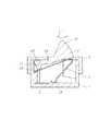
このような従来のスイッチについて、図5を用いて説明する。 Such a conventional switch will be described with reference to FIG.
図5は従来のスイッチの断面図であり、同図において、1は絶縁樹脂製で上面開放の箱形のケース、2は導電金属薄板製の固定接点で、複数の固定接点2がケース1の内底面に植設固定されると共に、その端子部(図示せず)が各々外方へ延出している。 FIG. 5 is a cross-sectional view of a conventional switch. In FIG. 5, 1 is a box-shaped case made of insulating resin and having an open top surface, 2 is a fixed contact made of a conductive metal thin plate, and a plurality of fixed contacts 2 are
そして、3は絶縁樹脂製のレバーで、左端の支点部3Aを支点としてケース1内に揺動可能に収納されると共に、右端には上方へ突出する操作部3Bが形成されている。
また、4は中間部が折曲された弾性金属薄板製の可動接点で、やや撓んだ状態でケース1内に収納され、一端の接触部4Aがケース1の内底面に弾接すると共に、他端の係止部4Bがレバー3下面の突出部3Cに係止されている。 Reference numeral 4 denotes a movable contact made of an elastic metal thin plate with a bent middle portion, and is housed in the
さらに、5は金属薄板製のカバーで、このカバー5がケース1上面の開口部を覆うと共に、カバー5の貫通孔5Aからレバー3の操作部3Bが上方へ突出して、スイッチが構成されている。 Further,
なお、このように構成されたスイッチは、先ず、インサート成形等によって内底面に固定接点2が植設固定されたケース1内に、上方から可動接点4を挿入した後、突出部3Cを可動接点4の係止部4Bに当接させ、可動接点4を撓めながらケース1内にレバー3を収納する。 The switch constructed in this manner is such that, first, the movable contact 4 is inserted from above into the
そして、この後、ケース1上面の開口部をカバー5で覆い、カバー5をケース1外壁等に固着して、スイッチの組立てが行われる。 After that, the opening on the upper surface of the
また、このように製作されたスイッチは、上下面に複数の配線パターンが形成された配線基板(図示せず)上に載置され、ケース1から延出した固定接点2の端子部が、所定の配線パターンに半田付けされて、機器の電子回路に電気的に接続される。 The switch manufactured in this way is placed on a wiring board (not shown) having a plurality of wiring patterns formed on the upper and lower surfaces, and the terminal portion of the fixed contact 2 extending from the
以上の構成において、テープやディスク等の記録媒体の挿抜、或いはツマミや扉等のメカニズムの動作によって、ケース1上方へ突出した操作部3Bが下方へ押圧操作されると、レバー3が支点部3Aを支点として下方へ揺動する。 In the above configuration, when the operation portion 3B protruding upward from the
これによって、可動接点4の中間部が操作部3B下面に押圧され、ケース1の内底面に弾接した可動接点4端部の接触部4Aが、左方の固定接点2の方向へケース1内底面上を弾接摺動する。 As a result, the intermediate portion of the movable contact 4 is pressed against the lower surface of the operation portion 3B, and the
そして、操作部3Bが所定量押圧されると、接触部4Aが固定接点2上に弾接し、可動接点4を介して複数の固定接点2の電気的接離が行われる。 When the operation portion 3B is pressed by a predetermined amount, the
また、レバー3への操作力が解除されると、可動接点4の弾性復帰力によって、レバー3が上方に押圧されて揺動すると共に、接触部4Aも固定接点2から右方のケース1内底面へ弾接摺動して、元の状態に復帰するように構成されている。 Further, when the operating force to the
なお、この出願の発明に関連する先行技術文献情報としては、例えば、特許文献1が知られている。
しかしながら、上記従来のスイッチにおいては、組立てを行う際、ケース1内に可動接点4を挿入した後、この可動接点4を突出部3Cで撓めながらケース1内にレバー3を収納しているため、可動接点4の外れや変形が生じ易く、製作にも時間を要するという課題があった。 However, in the above-described conventional switch, when assembling, the movable contact 4 is inserted into the
本発明は、このような従来の課題を解決するものであり、組立てが容易で、動作の確実なスイッチを提供することを目的とする。 The present invention solves such a conventional problem, and an object thereof is to provide a switch that is easy to assemble and reliably operates.
上記目的を達成するために本発明は、以下の構成を有するものである。 In order to achieve the above object, the present invention has the following configuration.
本発明の請求項1に記載の発明は、内底面に複数の固定接点が植設された箱形のケースと、このケース内に一端を支点として揺動可能に収納し、他端の上方を操作部として外方へ突出されたレバーと、二つのアーム部を備え、上記レバーの揺動によって上記アーム部の一端の接触部が、上記ケース内底面または上記固定接点上を弾接摺動する可動接点からなり、上記可動接点の二つのアーム部の他端間を連結する保持部を設けると共に、上記接触部を上記レバーの支点側に位置するように上記保持部の中間部を上記レバーの操作部下方内にインサート成形したものであり、可動接点の保持部の中間部をレバーの操作部下方内にインサート成形され、確実にレバーに保持されているため、組立ての際、可動接点の外れや変形が生じにくく、容易に組立てが行えると共に、操作時の可動接点の確実な動作が可能なスイッチを得ることができるという作用を有する。The invention according to
請求項2に記載の発明は、請求項1記載の発明において、可動接点の二つのアーム部の他端間を連結する保持部の中央に上記アーム部と平行方向に延出する舌片部を形成すると共に、この舌片部と上記保持部をレバー内にインサート成形したものであり、可動接点のレバー内へのインサート保持が、舌片部によってより強固なものとなるため、操作時の可動接点の動作がより確実となり、安定した電気的接離を行うことができるという作用を有する。Invention according to claim 2, in the invention according to the first aspect, the tongue portion extending in a direction parallel to thecentral tothe arm portionof the holding portionfor connecting the other ends of the two arms of the movable contact and forming, is obtained by insert molding the tongue piece portion andthe holding portion in the lever, since the insert retaining into the lever of the movable contact becomes a more robust by tongue, movable during operation The operation of the contact becomes more reliable, and it has an effect that stable electrical contact / separation can be performed.
以上のように本発明によれば、組立てが容易で、動作の確実なスイッチを実現することができるという有利な効果が得られる。 As described above, according to the present invention, it is possible to obtain an advantageous effect that a switch that is easy to assemble and can be reliably operated can be realized.
以下、本発明の実施の形態について、図1〜図4を用いて説明する。 Hereinafter, embodiments of the present invention will be described with reference to FIGS.
(実施の形態)
図1は本発明の一実施の形態によるスイッチの断面図、図2は同分解斜視図、図3は同要部分解斜視図であり、同図において、11は液晶ポリマーやポリフェニレンサルファイド等の絶縁樹脂製で上面開放の箱形のケース、12は銅合金等の導電金属薄板製の固定接点で、複数の固定接点12がケース11の内底面にインサート成形等によって植設固定されると共に、その端子部が各々外方へ延出している。(Embodiment)
1 is a cross-sectional view of a switch according to an embodiment of the present invention, FIG. 2 is an exploded perspective view of the same, FIG. 3 is an exploded perspective view of the same part, and 11 is an insulating material such as a liquid crystal polymer or polyphenylene sulfide. A box-shaped case made of resin and having an open top surface, 12 is a fixed contact made of a conductive metal thin plate such as a copper alloy, and a plurality of
そして、13は液晶ポリマーやナイロン等の絶縁樹脂製のレバーで、左端の支点部13Aを支点としてケース11内に揺動可能に収納されると共に、右端には上方へ突出する操作部13Bが形成されている。
また、14は銅合金等の弾性金属薄板製の可動接点で、二つのアーム部14Aがやや撓んだ状態でケース11内に収納され、このアーム部14A左端には、ケース11の内底面に弾接する略円弧状の接触部14Bが形成されると共に、右端には二つのアーム部14Aを連結する保持部14Cが設けられ、この保持部14Cの中間部が、レバー13の操作部13B下方内にインサート成形されている。
さらに、可動接点14の保持部14Cには、中央にアーム部14Aと平行方向に延出する舌片部14Dが設けられ、この舌片部14Dも保持部14Cと共にレバー13内にインサート成形されている。 Further, the holding portion 14C of the
そして、15は銅板等の金属薄板製のカバーで、このカバー15がケース11上面の開口部を覆うと共に、カバー15の貫通孔15Aからレバー13の操作部13Bが上方へ突出して、スイッチが構成されている。 A
なお、このように構成されたスイッチは、先ず、ケース11内底面にインサート成形等によって固定接点12を植設固定すると共に、レバー13の操作部13B下方に可動接点14の保持部14Cと舌片部14Dをインサート成形して、レバー13下面に可動接点14を固着保持し一体化する。 In the switch configured in this manner, first, the
そして、この一体化されたレバー13と可動接点14を、上方からケース11内に挿入し、アーム部14Aを撓めながらケース11内にレバー13を収納した後、ケース11上面の開口部をカバー15で覆い、カバー15をケース11外壁等に固着して、スイッチの組立てが行われる。 Then, the integrated
つまり、固定接点12が植設されたケース11と、可動接点14がインサート成形されたレバー13、及びカバー15の三つの部品だけで、スイッチの組立てが行われるように構成されている。 In other words, the switch is assembled by only three parts: the
また、この時、可動接点14は右端の保持部14Cと舌片部14Dが、レバー13内にインサート成形され、確実にレバー13に固着保持されているため、レバー13をケース11内に上方から挿入するだけで、滑らかにアーム部14Aが撓んで組立てが行えるようになっている。 At this time, since the
つまり、スイッチの組立てを行う際、可動接点14のレバー13からの外れや変形が生じにくく、組立てが容易に行えると共に、操作時の可動接点14の動作が確実に行われるように形成されている。 That is, when assembling the switch, the
また、このように製作されたスイッチは、上下面に複数の配線パターンが形成された配線基板(図示せず)上に載置され、ケース11から延出した固定接点12の端子部が、所定の配線パターンに半田付けされて、機器の電子回路に電気的に接続される。 Further, the switch manufactured in this way is placed on a wiring board (not shown) having a plurality of wiring patterns formed on the upper and lower surfaces, and the terminal portion of the fixed
以上の構成において、テープやディスク等の記録媒体の挿抜、或いはツマミや扉等のメカニズムの動作によって、ケース11上方へ突出した操作部13Bが下方へ押圧操作されると、図4の断面図に示すように、レバー13が支点部13Aを支点として下方へ揺動する。 In the above configuration, when the
そして、このレバー13の揺動に伴って、レバー13下面に右端が固着保持された可動接点14左端の接触部14Bが、左方の固定接点12の方向へケース11内底面上を弾接摺動し、操作部13Bが所定量押圧されると、接触部14Bが固定接点12上に弾接し、可動接点14を介して複数の固定接点12の電気的接離が行われる。 As the
また、レバー13への操作力が解除されると、可動接点14の弾性復帰力によって、レバー13が上方に押圧されて揺動すると共に、接触部14Bも固定接点12から右方のケース11内底面へ弾接摺動して、図1に示した元の状態に復帰する。 Further, when the operating force to the
なお、この時、可動接点14は保持部14Cに加え舌片部14Dもレバー13内にインサート成形され、可動接点14のレバー13内へのインサート保持が、舌片部14Dによってより強固なものとなっているため、レバー13の揺動操作を繰返した場合にも、レバー13からの可動接点14の脱落や剥がれのないように形成されている。 At this time, the
つまり、舌片部14Dによって、揺動操作時の可動接点14の動作がより確実となり、固定接点12との安定した電気的接離を行うことができるように構成されている。 That is, the tongue piece portion 14D is configured such that the operation of the
このように本実施の形態によれば、レバー13の揺動によってアーム部14A一端の接触部14Bが、ケース11内底面または固定接点12上を弾接摺動する可動接点14の、アーム部14A他端に保持部14Cを設けると共に、この保持部14Cをレバー13内にインサート成形することによって、可動接点14がレバー13に確実に保持されているため、組立ての際、可動接点14の外れや変形が生じにくく、容易に組立てが行えると共に、操作時の可動接点14の確実な動作が可能なスイッチを得ることができるものである。 As described above, according to the present embodiment, the
また、可動接点14の保持部14Cにアーム部14Aと平行方向に延出する舌片部14Dを形成すると共に、この舌片部14Dと保持部14Cをレバー13内にインサート成形することによって、可動接点14のレバー13内へのインサート保持がより強固なものとなるため、操作時の可動接点14の動作がより確実となり、安定した電気的接離を行うことができる。 Further, a tongue piece portion 14D extending in a direction parallel to the
本発明によるスイッチは、組立てが容易で、動作の確実なものを得ることができ、主に各種電子機器に使用される検出用スイッチとして有用である。 The switch according to the present invention can be easily assembled and can be reliably operated, and is useful as a detection switch mainly used in various electronic devices.
11 ケース
12 固定接点
13 レバー
13A 支点部
13B 操作部
14 可動接点
14A アーム部
14B 接触部
14C 保持部
14D 舌片部
15 カバー
15A 貫通孔DESCRIPTION OF
Claims (2)
Translated fromJapanesePriority Applications (3)
| Application Number | Priority Date | Filing Date | Title |
|---|---|---|---|
| JP2005142641AJP4687232B2 (en) | 2005-05-16 | 2005-05-16 | switch |
| US11/400,234US7202432B2 (en) | 2005-05-16 | 2006-04-10 | Switch |
| CNB200610080302XACN100446145C (en) | 2005-05-16 | 2006-05-09 | switch |
Applications Claiming Priority (1)
| Application Number | Priority Date | Filing Date | Title |
|---|---|---|---|
| JP2005142641AJP4687232B2 (en) | 2005-05-16 | 2005-05-16 | switch |
Publications (2)
| Publication Number | Publication Date |
|---|---|
| JP2006318851A JP2006318851A (en) | 2006-11-24 |
| JP4687232B2true JP4687232B2 (en) | 2011-05-25 |
Family
ID=37418061
Family Applications (1)
| Application Number | Title | Priority Date | Filing Date |
|---|---|---|---|
| JP2005142641AExpired - LifetimeJP4687232B2 (en) | 2005-05-16 | 2005-05-16 | switch |
Country Status (3)
| Country | Link |
|---|---|
| US (1) | US7202432B2 (en) |
| JP (1) | JP4687232B2 (en) |
| CN (1) | CN100446145C (en) |
Families Citing this family (9)
| Publication number | Priority date | Publication date | Assignee | Title |
|---|---|---|---|---|
| CN201084590Y (en)* | 2007-04-04 | 2008-07-09 | 鸿富锦精密工业(深圳)有限公司 | Key module |
| JP4962179B2 (en) | 2007-07-11 | 2012-06-27 | パナソニック株式会社 | switch |
| TWI356430B (en)* | 2008-01-10 | 2012-01-11 | Primax Electronics Ltd | Micro switch |
| TWI390569B (en)* | 2008-11-20 | 2013-03-21 | Altek Corp | Mode dial mechanism and electronic device having the same |
| USD761212S1 (en) | 2013-11-21 | 2016-07-12 | Omron Corporation | Push switch |
| USD761211S1 (en) | 2013-11-21 | 2016-07-12 | Omron Corporation | Push switch |
| USD743917S1 (en)* | 2013-11-21 | 2015-11-24 | Omron Corporation | Push switch |
| JP6890512B2 (en)* | 2017-09-15 | 2021-06-18 | 株式会社Lixil | Remote control device and toilet system |
| DE102019115773B4 (en)* | 2019-06-11 | 2021-11-18 | Hoover Dam Technology Gmbh | Switch for making and breaking an electrical connection |
Family Cites Families (13)
| Publication number | Priority date | Publication date | Assignee | Title |
|---|---|---|---|---|
| ES414752A2 (en)* | 1973-05-14 | 1977-07-01 | Amp Inc | An electrical switch device. (Machine-translation by Google Translate, not legally binding) |
| US4012608A (en)* | 1974-08-20 | 1977-03-15 | Amp Incorporated | Miniature switch with substantial wiping action |
| DE4222794C2 (en)* | 1991-07-13 | 1994-10-13 | Mitsuku Denshi Kogyo | Pressure switch |
| JP3248392B2 (en)* | 1995-06-06 | 2002-01-21 | 松下電器産業株式会社 | Lever switch |
| JPH09245573A (en)* | 1996-03-04 | 1997-09-19 | Alps Electric Co Ltd | Rotary switch |
| US5967302A (en)* | 1998-03-06 | 1999-10-19 | Lin; Hsi-Chi | Dual inline package switch |
| JP3015023B1 (en)* | 1999-03-18 | 2000-02-28 | 株式会社サガミ電子工業 | Push button switch |
| JP3893824B2 (en)* | 1999-12-27 | 2007-03-14 | 松下電器産業株式会社 | Lever switch and detection device using the same |
| JP4019601B2 (en)* | 2000-04-14 | 2007-12-12 | 松下電器産業株式会社 | Lever switch |
| CN1293584C (en)* | 2003-01-29 | 2007-01-03 | 松下电器产业株式会社 | Lever switch |
| JP2005026035A (en) | 2003-07-01 | 2005-01-27 | Matsushita Electric Ind Co Ltd | switch |
| JP2005116347A (en)* | 2003-10-08 | 2005-04-28 | Matsushita Electric Ind Co Ltd | switch |
| US6917008B1 (en)* | 2004-01-06 | 2005-07-12 | Zippy Technology Corp. | Microswitch |
- 2005
- 2005-05-16JPJP2005142641Apatent/JP4687232B2/ennot_activeExpired - Lifetime
- 2006
- 2006-04-10USUS11/400,234patent/US7202432B2/ennot_activeExpired - Fee Related
- 2006-05-09CNCNB200610080302XApatent/CN100446145C/enactiveActive
Also Published As
| Publication number | Publication date |
|---|---|
| JP2006318851A (en) | 2006-11-24 |
| CN1866442A (en) | 2006-11-22 |
| US20060254901A1 (en) | 2006-11-16 |
| US7202432B2 (en) | 2007-04-10 |
| CN100446145C (en) | 2008-12-24 |
Similar Documents
| Publication | Publication Date | Title |
|---|---|---|
| CN100446145C (en) | switch | |
| CN102436940B (en) | Switching device | |
| JP4862697B2 (en) | Switch device | |
| JP4962179B2 (en) | switch | |
| JP4595741B2 (en) | switch | |
| JP4618155B2 (en) | Lever switch | |
| JP4830793B2 (en) | switch | |
| US20040223416A1 (en) | Lever switch | |
| JP2005026035A (en) | switch | |
| JP4770652B2 (en) | Lever switch | |
| JP4172309B2 (en) | Lever switch | |
| US6353196B2 (en) | Water-resistant switching device | |
| US7102094B2 (en) | Switch | |
| JP2011100626A (en) | Lever switch | |
| CN102856108A (en) | Switch | |
| JP2004253378A (en) | Lever switch | |
| JP5317243B2 (en) | Switch device | |
| JP3157249U (en) | switch | |
| JP4619196B2 (en) | Sliding electronic parts with pressure switch | |
| JP2012190576A (en) | Lever switch | |
| JP5013300B2 (en) | Card connector with half-insertion status detection switch | |
| JP2012089363A (en) | Switch | |
| JP2013214490A (en) | Lever switch | |
| JP2014132526A (en) | Lever switch |
Legal Events
| Date | Code | Title | Description |
|---|---|---|---|
| A621 | Written request for application examination | Free format text:JAPANESE INTERMEDIATE CODE: A621 Effective date:20080115 | |
| RD01 | Notification of change of attorney | Free format text:JAPANESE INTERMEDIATE CODE: A7421 Effective date:20080213 | |
| RD01 | Notification of change of attorney | Free format text:JAPANESE INTERMEDIATE CODE: A7421 Effective date:20091126 | |
| A131 | Notification of reasons for refusal | Free format text:JAPANESE INTERMEDIATE CODE: A131 Effective date:20100907 | |
| A521 | Request for written amendment filed | Free format text:JAPANESE INTERMEDIATE CODE: A523 Effective date:20101015 | |
| TRDD | Decision of grant or rejection written | ||
| A01 | Written decision to grant a patent or to grant a registration (utility model) | Free format text:JAPANESE INTERMEDIATE CODE: A01 Effective date:20110118 | |
| A01 | Written decision to grant a patent or to grant a registration (utility model) | Free format text:JAPANESE INTERMEDIATE CODE: A01 | |
| A61 | First payment of annual fees (during grant procedure) | Free format text:JAPANESE INTERMEDIATE CODE: A61 Effective date:20110131 | |
| R151 | Written notification of patent or utility model registration | Ref document number:4687232 Country of ref document:JP Free format text:JAPANESE INTERMEDIATE CODE: R151 | |
| FPAY | Renewal fee payment (event date is renewal date of database) | Free format text:PAYMENT UNTIL: 20140225 Year of fee payment:3 | |
| EXPY | Cancellation because of completion of term |