JP4686281B2 - Respiratory state determination device, respiratory state measurement method, and respiratory state determination program - Google Patents
Respiratory state determination device, respiratory state measurement method, and respiratory state determination programDownload PDFInfo
- Publication number
- JP4686281B2 JP4686281B2JP2005198082AJP2005198082AJP4686281B2JP 4686281 B2JP4686281 B2JP 4686281B2JP 2005198082 AJP2005198082 AJP 2005198082AJP 2005198082 AJP2005198082 AJP 2005198082AJP 4686281 B2JP4686281 B2JP 4686281B2
- Authority
- JP
- Japan
- Prior art keywords
- respiratory
- sound
- subject
- state determination
- synchronization component
- Prior art date
- Legal status (The legal status is an assumption and is not a legal conclusion. Google has not performed a legal analysis and makes no representation as to the accuracy of the status listed.)
- Expired - Fee Related
Links
Images


Classifications
- A—HUMAN NECESSITIES
- A61—MEDICAL OR VETERINARY SCIENCE; HYGIENE
- A61B—DIAGNOSIS; SURGERY; IDENTIFICATION
- A61B7/00—Instruments for auscultation
- A61B7/003—Detecting lung or respiration noise
Landscapes
- Health & Medical Sciences (AREA)
- Life Sciences & Earth Sciences (AREA)
- Medical Informatics (AREA)
- Engineering & Computer Science (AREA)
- Biomedical Technology (AREA)
- Heart & Thoracic Surgery (AREA)
- Pulmonology (AREA)
- Molecular Biology (AREA)
- Surgery (AREA)
- Animal Behavior & Ethology (AREA)
- General Health & Medical Sciences (AREA)
- Public Health (AREA)
- Veterinary Medicine (AREA)
- Measurement Of The Respiration, Hearing Ability, Form, And Blood Characteristics Of Living Organisms (AREA)
Description
Translated fromJapanese本発明は、被験者の呼吸状態を判定する呼吸状態判定装置、呼吸状態測定方法および呼吸状態判定プログラムに関するものである。The present invention relates to a respiratory state determination device, a respiratory statemeasurement method, and a respiratory state determination program that determine a respiratory state of a subject.
近年、鉄道、自動車などの運転手の運転中の居眠りによる事故が問題となっている。その原因のひとつとして、睡眠時無呼吸症候群が関心を集めている。また、このような完全な無呼吸とまではいかなくとも、低酸素状態になることがある。これは、枕の高さが合わないことなどに起因する。 In recent years, accidents caused by falling asleep while driving drivers such as railways and cars have become a problem. One of the causes is sleep apnea syndrome. In addition, even if it is not such complete apnea, hypoxia may occur. This is due to the fact that the height of the pillow does not match.
また、いす型チャイルドシードや、ベビーカーによる子供の低酸素症も問題となっている。その他、喘息発作が睡眠時に起きやすいこと、慢性閉塞性肺疾患(COPD)が、例えば米国では1600万人とも言われるように増加していることもあり、睡眠時の呼吸状態の計測に関心が集まっている。 In addition, chair child seeds and children's hypoxia caused by strollers are also a problem. In addition, asthma attacks are likely to occur during sleep, and chronic obstructive pulmonary disease (COPD) is increasing, for example, as it is said to be 16 million people in the United States. Gathered.
睡眠時の呼吸計測に関しては、低拘束である必要があり、枕やマットレスにセンサを内蔵し、心拍や呼吸数を計測する方法の研究開発が進められている。外部設置マイクにおいて、いびきなど呼吸に関する音を計測する方法も考案されている。また、体に装着した音センサにより肺音を計測し、喘息時に発生するラ音と呼ばれる音を計測する方法も検討されている(特許文献1)。 Respiratory measurement during sleep needs to be low-restraint, and research and development of methods for measuring heart rate and respiratory rate by incorporating sensors in pillows and mattresses are underway. A method of measuring sounds related to breathing, such as snoring, using an external microphone has been devised. In addition, a method of measuring a lung sound with a sound sensor attached to the body and measuring a sound called rale generated during asthma has been studied (Patent Document 1).
上述のように寝具に内蔵する心拍呼吸センサは、呼吸に伴う胸部の動きに伴う低周波振動(〜1Hz)を計測するものである。そのため、完全な無呼吸ではない、例えば気道閉塞状態や歯ぎしりなどの帯域の高いものを計測するのは困難である。また、外部設置マイクでは、いびきや歯ぎしりなど外部に音として現れない場合には計測できない。このため、呼吸閉塞状態による音の変化などを捉えるのは困難である。 As described above, the heartbeat respiration sensor built in the bedding measures low frequency vibration (˜1 Hz) accompanying the movement of the chest accompanying respiration. For this reason, it is difficult to measure a thing with a high band such as an airway obstruction state or a bruxism that is not complete apnea. Also, with an external microphone, measurement is not possible if it does not appear as sound, such as snoring or bruxism. For this reason, it is difficult to capture a change in sound due to a respiratory obstruction.
本発明は、上記に鑑みてなされたものであって気道閉塞状態や呼吸閉塞状態など様々な症状を判定することのできる呼吸状態判定装置を提供することを目的とする。 The present invention has been made in view of the above, and an object of the present invention is to provide a respiratory state determination device capable of determining various symptoms such as an airway obstruction state and a respiratory obstruction state.
上述した課題を解決し、目的を達成するために、本発明は、被験者の気道を通過する呼吸音を計測し、前記呼吸音に応じた信号を出力する呼吸音計測手段と、前記信号を整流積分して得られる包絡線の最大値および最小値それぞれを周波数変換して周波数スペクトルを算出し、前記最大値に対する周波数スペクトルと前記最小値に対する周波数スペクトルとの差分を表す呼吸同期成分を抽出する呼吸同期成分抽出手段と、前記被験者の正常な状態における呼吸同期成分に対する、抽出された呼吸同期成分の周波数成分のシフト量を表す周波数シフトが所定の値以上である場合に、前記被験者の呼吸状態が悪化していると判定する呼吸状態判定手段とを備えたことを特徴とする。In order to solve the above-described problems and achieve the object, the present invention measures respiratory sound passing through a subject's airwayand outputs a signal corresponding to the respiratory sound,and rectifies the signal. Respiration for extracting a respiratory synchronization componentrepresenting a difference between a frequency spectrum for the maximum value and a frequency spectrum for the minimum value by calculating a frequency spectrum by frequency-converting each of the maximum value and the minimum value of the envelope obtained by integration Whenthe frequency shift indicating the shift amount of the frequency component of the extracted respiratory synchronization component with respect to the synchronization component extraction means and therespiratory synchronization component in the normal state of the subjectis equal to or greater than a predetermined value, the respiratory state of the subjectis And a breathing state determining meansfor determining that the conditionhas deteriorated .
本発明にかかる呼吸状態判定装置によれば、睡眠時の呼吸に関する様々な症状を判定することができるという効果を奏する。According to the respiratory condition determination device of the present invention, it is possible to determine various symptoms related to breathingduring sleep .
以下に、本発明にかかる呼吸状態判定装置、呼吸状態測定方法および呼吸状態判定プログラムの実施の形態を図面に基づいて詳細に説明する。Embodiments of a respiratory condition determination device, a respiratory conditionmeasurement method, and a respiratory condition determination program according to the present invention will be described below in detail with reference to the drawings.
(実施の形態1)
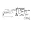
図1は、本実施の形態にかかる呼吸状態判定装置10の全体構成を示すブロック図である。呼吸状態判定装置10は、被験者の皮膚に接触し、被験者の気道を通過する呼吸音を検出する複数のセンサ111〜120を備えたセンサアレイ110と、信号増幅部130と、周波数変換部132と、呼吸同期成分抽出部134と、周波数シフト検出部136と、呼吸状態判定部138と、呼吸同期成分比較部140と、センサ選択部142と、入眠前呼吸同期成分保持部150とを備えている。(Embodiment 1)
FIG. 1 is a block diagram showing an overall configuration of a respiratory
信号増幅部130は、各センサ111〜120から検出した呼吸音の信号を増幅する。周波数変換部132は、フーリエ変換などの周波数変換により、増幅後の呼吸音の信号から周波数スペクトルを得る。 The
呼吸同期成分抽出部134は、周波数変換部132により得られた周波数スペクトルから呼吸同期成分を抽出する。ここで、呼吸同期成分とは、周波数変換部132により得られた周波数スペクトルのうち、被験者の呼吸に同期して変化する成分のことである。 The respiratory synchronization component extraction unit 134 extracts a respiratory synchronization component from the frequency spectrum obtained by the frequency conversion unit 132. Here, the respiratory synchronization component is a component that changes in synchronization with the breathing of the subject in the frequency spectrum obtained by the frequency conversion unit 132.
入眠前呼吸同期成分保持部150は、被験者の入眠前呼吸同期成分を保持しておく。具体的には、入眠前の被験者の呼吸音に対し、信号増幅部130から呼吸同期成分抽出部134の各処理により呼吸同期成分を得る。そして、これを入眠前呼吸同期成分として保持する。入眠前の呼吸状態は正常であると考えられる。そこで、このとき得られた呼吸同期成分を正常状態(健常な状態)における呼吸同期成分として保持することとしている。 The sleep-synchronized respiratory synchronization
周波数シフト検出部136は、呼吸同期成分抽出部134により得られた呼吸同期成分の周波数成分の変化、すなわち周波数シフトを検出する。呼吸状態判定部138は、周波数シフト検出部136が検出した周波数シフトに基づいて、呼吸状態を判定する。 The frequency
一方、呼吸同期成分比較部140は、各センサ111〜120が検出した呼吸音の信号それぞれに対し、呼吸同期成分抽出部134が検出した呼吸同期成分を比較する。センサ選択部142は、呼吸同期成分比較部140による比較結果に基づいて、呼吸状態判定部138が呼吸判定を行う対象とする呼吸音を検出すべきセンサを複数のセンサ111〜120の中から1つ選択する。 On the other hand, the respiratory synchronization
図2は、呼吸状態判定装置10を内蔵した枕の外観図である。図2に示すように枕のうち、被験者の頸部があたる部分は、他の部分に比べて凸状に形成されている。複数のセンサ111〜120は、この凸部において枕の横方向に一列に配置されている。 FIG. 2 is an external view of a pillow incorporating the respiratory
このように、複数のセンサを備えているので、被験者が睡眠中に寝返りを打ち、被験者と所定のセンサとの接触状態が悪くなった場合であっても、そのときに接触している他のセンサにより呼吸音の信号を検出することができる。 As described above, since the plurality of sensors are provided, even if the subject turns over during sleep and the contact state between the subject and the predetermined sensor deteriorates, the other contact at that time A respiratory sound signal can be detected by the sensor.
図3は、第1センサ111の外観図である。センサ111は、ポリミドやポリエステルなどの誘電体で形成された基板1110と、基板1110の両端に設けられた電極1112,1114とを有している。センサ111の電極方向200における厚さは、2mm程度である。また、電極1112,1114のサイズは、3cm×3cmである。なお、他のセンサ112〜130の構成は、第1センサ111の構成と同様である。のどの詰まりなどによる呼吸状態の変化を検出する観点からは、いずれの場合においても、各センサは数100Hz程度の周波数を検出可能であることが望ましい。 FIG. 3 is an external view of the
また、本実施の形態にかかる各センサ111〜120はそれぞれ独立し形成されていたが、これにかえて、各センサ111〜120は一体に設けられてもよい。 Moreover, although each sensor 111-120 concerning this Embodiment was each formed independently, it replaces with this and each sensor 111-120 may be provided integrally.
図4は、センサアレイ110等のより詳細な構成を示す図である。センサ111〜120としては、コンデンサマイクを使用し、直流のバイアス電圧を印加する。センサ選択部142には、マルチプレクサを使用する。また、信号増幅部130には、CV変換回路を使用し、電圧変換後増幅を行う。増幅後の信号は、AD変換されCPUに入力される。そして、CPUにおいて、周波数変換部132、呼吸同期成分抽出部134、周波数シフト検出部136、呼吸状態判定部138、呼吸同期成分比較部140、センサ選択部142、および入眠前呼吸同期成分保持部150の処理が行われる。 FIG. 4 is a diagram showing a more detailed configuration of the
CPUは、各センサから得られた呼吸同期成分に基づいて、センサを選択し、選択したセンサを特定するセレクト信号をマルチプレクサに入力する。マルチプレクサは、セレクト信号にしたがい所定のセンサを選択する。 The CPU selects a sensor based on the respiratory synchronization component obtained from each sensor, and inputs a select signal for specifying the selected sensor to the multiplexer. The multiplexer selects a predetermined sensor according to the select signal.
なお、センサとしては、コンデンサマイクにかえて圧力センサを使用してもよい。この場合には、例えば、交流の100kHz程度のサイン波を印加する。また、信号増幅後、印加電圧と同等の周波数で検波することにより印加周波数成分が除去された後、AD変換される。また他の例としては、信号増幅後、ローパスフィルタで印加周波数成分を除去してもよい。 As the sensor, a pressure sensor may be used instead of the condenser microphone. In this case, for example, an alternating sine wave of about 100 kHz is applied. Further, after signal amplification, the applied frequency component is removed by detection at a frequency equivalent to the applied voltage, and then AD conversion is performed. As another example, the applied frequency component may be removed by a low-pass filter after signal amplification.
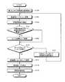
図5は、呼吸状態判定装置10における呼吸状態判定処理を示すフローチャートである。まず、予め定められたセンサ、例えば第1センサ111が検出した、睡眠中の被験者の呼吸音の信号に対する呼吸同期成分を抽出する。 FIG. 5 is a flowchart showing a respiratory state determination process in the respiratory
具体的には、まず、第1センサ111は、睡眠中の被験者の呼吸音の信号を検出する(ステップS100)。次に、第1センサ111から取得した呼吸音の信号は、増幅された後、周波数変換部132により周波数変換され、周波数スペクトルが得られる(ステップS102)。 Specifically, first, the
次に、呼吸同期成分抽出部134は、周波数スペクトルから呼吸同期成分を抽出する(ステップS104)。なおこのとき検出された呼吸同期成分を睡眠中呼吸同期成分と称する。 Next, the respiratory synchronization component extraction unit 134 extracts a respiratory synchronization component from the frequency spectrum (step S104). The respiratory synchronization component detected at this time is referred to as a sleep synchronization component during sleep.
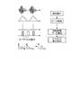
図6は、呼吸同期成分抽出処理(ステップS104)を説明するための図である。図6に示すように、まずセンサの出力を整流積分し包絡線を求める。次に、包絡線における最大値および最小値を検出する。検出した最大値および最小値それぞれの時刻のデータを元に周波数変換し、最大値、最小値それぞれの周波数スペクトルを取得する。これらの周波数スペクトルの差分を呼吸同期成分として抽出する。 FIG. 6 is a diagram for explaining the respiratory synchronization component extraction process (step S104). As shown in FIG. 6, first, the output of the sensor is rectified and integrated to obtain an envelope. Next, the maximum value and the minimum value in the envelope are detected. Frequency conversion is performed based on the detected time data of the maximum value and the minimum value, and frequency spectra of the maximum value and the minimum value are obtained. A difference between these frequency spectra is extracted as a respiratory synchronization component.
再び説明を図5に戻す。呼吸同期成分を抽出した後(ステップS104)、抽出した呼吸同期成分の時間波形の振幅の最大値と予め設定した閾値とを比較する。振幅の最大値が閾値以上である場合には(ステップS106,Yes)、センサにおいて良好な状態で呼吸音を検出できていると判断し、このセンサをセンサ候補として保持する(ステップS108)。 The description returns to FIG. 5 again. After extracting the respiratory synchronization component (step S104), the maximum value of the time waveform amplitude of the extracted respiratory synchronization component is compared with a preset threshold value. If the maximum value of the amplitude is equal to or greater than the threshold value (Yes at Step S106), it is determined that the respiratory sound can be detected in a good state in the sensor, and this sensor is held as a sensor candidate (Step S108).
一方、振幅の最大値が閾値未満である場合には(ステップS106,No)、検出結果が適切でないと判断し、このセンサをセンサ候補とせずに、ステップS110へ進む。 On the other hand, if the maximum value of the amplitude is less than the threshold (No in step S106), it is determined that the detection result is not appropriate, and the process proceeds to step S110 without setting this sensor as a sensor candidate.
すべてのセンサ111〜120に対する呼吸同期成分の振幅の最大値と閾値との比較処理が完了していない場合には(ステップS110,No)、まだ比較処理が完了していない他のセンサにおいて呼吸音の信号を検出する(ステップS120)。次に、再びステップS102へ戻り、検出した呼吸音の信号から周波数スペクトルを得る。 If the comparison process between the maximum value of the amplitude of the respiratory synchronization component and the threshold value for all the
すべてのセンサに対する比較処理が完了すると(ステップS110,Yes)、ステップS108において保持されたセンサ候補の中から、呼吸同期成分の時間波形の振幅が最大となるセンサを選択する(ステップS112)。以上で、呼吸判定に利用すべきセンサを選択することができる。 When the comparison process for all the sensors is completed (step S110, Yes), the sensor that maximizes the amplitude of the time waveform of the respiratory synchronization component is selected from the sensor candidates held in step S108 (step S112). As described above, a sensor to be used for breathing determination can be selected.
次に、周波数シフト検出部136は、選択したセンサの検出結果から得られた睡眠中呼吸同期成分と、入眠前呼吸同期成分保持部150が保持している入眠前呼吸同期成分とを比較し、入眠前呼吸同期成分に対する、選択したセンサにおける睡眠中呼吸同期成分の周波数シフトを検出する(ステップS114)。次に、呼吸状態判定部138は、周波数シフトに基づいて呼吸状態を判定する(ステップS116)。 Next, the frequency
具体的には、選択したセンサの呼吸同期成分が最大となる周波数が、入眠前呼吸同期成分に基づいて予め設定した値を超えてシフトした場合には、呼吸が閉塞状態であると判定する。 Specifically, when the frequency at which the respiratory synchronization component of the selected sensor is maximized is shifted beyond a preset value based on the respiratory synchronization component before falling asleep, it is determined that the breathing is in an obstructed state.
なお、被験者の就寝前に入眠前呼吸同期成分を検出し保持しておく。具体的には、就寝前の状態において、ステップS100〜ステップS112の処理により選択されたセンサにおける呼吸同期成分を入眠前呼吸同期成分として検出する。 Note that the pre-sleep respiratory synchronization component is detected and held before the subject goes to bed. Specifically, in the state before going to bed, the respiratory synchronization component in the sensor selected by the processing in steps S100 to S112 is detected as the respiratory synchronization component before falling asleep.
なお、本実施の形態においては、呼吸同期成分が最大となる周波数を基準としたが、呼吸同期成分が最大となる周波数にかえて、呼吸同期成分が中間値をとる周波数、すなわち中心周波数を基準としてもよい。また他の例としては、重心の周波数を基準としてもよい。 In this embodiment, the frequency at which the respiratory synchronization component is maximized is used as a reference. However, the frequency at which the respiratory synchronization component takes an intermediate value, that is, the center frequency is used as a reference instead of the frequency at which the respiratory synchronization component is maximized. It is good. As another example, the center of gravity frequency may be used as a reference.
図7−1および図7−2は、呼吸同期成分の周波数シフトを説明するための図である。図7−1は、正常な状態における呼吸同期成分を示す図である。図7−2は、呼吸状態が悪化した場合の呼吸同期成分を示す図である。このように、正常な状態において400Hz近傍に見られた呼吸同期成分のピークは、例えば高すぎる枕を使用し首に負担をかけた状態には、図7−2に示すように、より低周波数側へシフトする。すなわち、周波数シフトを検出することにより、首の負担等に起因したのどの詰まりなどの異常を検出することができる。 7A and 7B are diagrams for explaining the frequency shift of the respiratory synchronization component. FIG. 7-1 is a diagram illustrating a respiratory synchronization component in a normal state. FIG. 7-2 is a diagram illustrating a respiratory synchronization component when the respiratory state deteriorates. In this way, the peak of the respiratory synchronization component seen in the vicinity of 400 Hz in the normal state is, for example, a lower frequency as shown in FIG. Shift to the side. That is, by detecting the frequency shift, it is possible to detect abnormalities such as clogging of the throat caused by a burden on the neck.
なお、図7−1および図7−2に示すデータは、センサにより計測された計測音すべての周波数変換により得られた周波数スペクトルである。実際には、これと呼吸音が入っていないときの周波数スペクトルとの差分により呼吸同期成分を抽出する。 The data shown in FIGS. 7-1 and 7-2 is a frequency spectrum obtained by frequency conversion of all the measurement sounds measured by the sensor. Actually, the respiratory synchronization component is extracted based on the difference between this and the frequency spectrum when no breathing sound is contained.
以上の呼吸状態判定処理により得られた呼吸状態判定結果は、例えばグラフとして表示してもよい。具体的には、例えば一晩において得られた呼吸状態悪化状態の回数、積算時間などを、被験者の起床時にモニタに表示してもよい。また、他の例としては、時間帯ごとの呼吸状態悪化の回数をグラフ表示してもよい。 The respiratory state determination result obtained by the above respiratory state determination process may be displayed as a graph, for example. Specifically, for example, the number of respiratory state deterioration states obtained overnight and the accumulated time may be displayed on the monitor when the subject wakes up. As another example, the number of respiratory state deteriorations for each time zone may be displayed in a graph.
図8は、実施の形態1に係る呼吸状態判定装置10のハードウェア構成を示す図である。呼吸状態判定装置10は、ハードウェア構成として、呼吸状態判定装置10における呼吸状態判定処理を実行する呼吸状態判定プログラムなどが格納されているROM52と、ROM52内のプログラムに従って呼吸状態判定装置10の各部を制御するCPU51と、呼吸状態判定装置10の制御に必要な種々のデータを記憶するRAM53と、ネットワークに接続して通信を行う通信I/F57と、各部を接続するバス62とを備えている。 FIG. 8 is a diagram illustrating a hardware configuration of the respiratory
先に述べた呼吸状態判定装置10における呼吸状態判定プログラムは、インストール可能な形式又は実行可能な形式のファイルでCD−ROM、フロッピー(R)ディスク(FD)、DVD等のコンピュータで読み取り可能な記録媒体に記録されて提供されてもよい。 The respiratory state determination program in the respiratory
この場合には、呼吸状態判定プログラムは、呼吸状態判定装置10において上記記録媒体から読み出して実行することにより主記憶装置上にロードされ、上記ソフトウェア構成で説明した各部が主記憶装置上に生成されるようになっている。 In this case, the respiratory condition determination program is loaded onto the main storage device by being read from the recording medium and executed by the respiratory
また、本実施の形態の呼吸状態判定プログラムを、インターネット等のネットワークに接続されたコンピュータ上に格納し、ネットワーク経由でダウンロードさせることにより提供するように構成しても良い。 Further, the respiratory condition determination program of the present embodiment may be provided by being stored on a computer connected to a network such as the Internet and downloaded via the network.
以上、本発明を実施の形態を用いて説明したが、上記実施の形態に多様な変更または改良を加えることができる。 As described above, the present invention has been described using the embodiment, but various changes or improvements can be added to the above embodiment.
そうした第1の変更例としては、実施の形態においては、ステップS106では、呼吸同期成分の時間波形の振幅の最大値と閾値とを比較したが、これにかえて、呼吸同期成分の相関関数の最大値と、相関関係に対して予め設定された閾値とを比較し、呼吸同期成分の相関関数の最大値が閾値以上である場合に、このセンサをセンサ候補として保持する(ステップS108)こととしてもよい。この場合にも、呼吸音を良好な状態で検出しているセンサをセンサ候補として選択することができる。 As such a first modification, in the embodiment, in step S106, the maximum value of the amplitude of the time waveform of the respiratory synchronization component is compared with the threshold value, but instead, the correlation function of the respiratory synchronization component is changed. The maximum value is compared with a threshold value set in advance for the correlation, and when the maximum value of the correlation function of the respiratory synchronization component is equal to or greater than the threshold value, this sensor is held as a sensor candidate (step S108). Also good. Also in this case, a sensor that detects a breathing sound in a good state can be selected as a sensor candidate.
また、第2の変更例としては、本実施の形態にかかる呼吸状態判定装置10は、被験者の入眠前呼吸同期成分を基準とした周波数シフトに基づいて被験者の睡眠状態を判定したが、これにかえて、被験者の呼吸音から過去に得られた呼吸同期成分を基準とした周波数シフトに基づいて、被験者の睡眠状態を判定してもよい。 As a second modification, the respiratory
具体的には、睡眠時に当該呼吸状態判定装置10において健康状態を判定した場合に得られた呼吸同期成分を、被験者における履歴情報として保持しておく。そして、履歴情報として保持されている呼吸同期成分を基準として周波数シフトを検出してもよい。 Specifically, the respiratory synchronization component obtained when the respiratory
さらに、履歴情報として複数の呼吸同期成分が保持されている場合には、複数の呼吸同期信号の平均値や標準偏差などを算出し、算出された呼吸同期成分を基準として周波数シフトを検出してもよい。 Furthermore, when multiple respiratory synchronization components are held as history information, the average value or standard deviation of multiple respiratory synchronization signals is calculated, and frequency shifts are detected based on the calculated respiratory synchronization components. Also good.
また、第3の変更例としては、センサにおける検出結果に基づいて、呼吸音が発生した時刻をさらに検出してもよい。そして、このときの呼吸音を取得することにより、実施の形態において説明した整流積分などの処理を省略することができる。 As a third modification, the time when the breathing sound is generated may be further detected based on the detection result of the sensor. Then, by acquiring the breathing sound at this time, processing such as rectification integration described in the embodiment can be omitted.
また、第4の変更例としては、本実施の形態においては、振幅の最大値に基づいて、睡眠状態判定に利用するセンサを選択したが、振幅の最大値に加えて、さらに隣接するセンサ間における電気的なインピーダンス変化に基づいて、センサを選択してもよい。 Further, as a fourth modification example, in the present embodiment, the sensor used for the sleep state determination is selected based on the maximum value of the amplitude, but in addition to the maximum value of the amplitude, between adjacent sensors. The sensor may be selected based on the electrical impedance change at.
具体的には、各隣接するセンサの間の電気的なインピーダンス変化の測定結果に基づいて、被験者に接触しているセンサを第1のセンサ候補として選択する。さらに、インピーダンス変化に基づいて選択された第1のセンサ候補に対し、実施の形態において説明したように、振幅の最大値と閾値とを比較することにより、さらに第2のセンサ候補を選択する。そして、第2のセンサ候補のうち最大振幅を示すセンサを選択する。 Specifically, a sensor in contact with the subject is selected as a first sensor candidate based on the measurement result of the electrical impedance change between each adjacent sensor. Further, as described in the embodiment, the second sensor candidate is further selected by comparing the maximum value of the amplitude and the threshold value with respect to the first sensor candidate selected based on the impedance change. Then, the sensor indicating the maximum amplitude is selected from the second sensor candidates.
このように、2段階にセンサを選択することにより、センサ選択にかかる処理の高速化を図ることができる。なおここで、第1のセンサ候補は、特許請求の範囲にかかるセンサ候補に対応する。 Thus, by selecting a sensor in two stages, it is possible to speed up the process for sensor selection. Here, the first sensor candidate corresponds to the sensor candidate according to the claims.
また、第5の変更例としては、呼吸状態判定装置10は寝具に内蔵されていればよく、枕にかえてシーツに内蔵されていてもよい。 As a fifth modification, the breathing
(実施の形態2)
図9は、実施の形態2にかかる呼吸状態判定装置10の外観図である。各センサ111〜120の下に複数のエアバッグ301〜310が設けられている。1つのセンサに対し、1つのエアバッグが設けられている。本実施の形態にかかるエアバッグは、特許請求の範囲に記載の押し付け部材に対応する。(Embodiment 2)
FIG. 9 is an external view of the respiratory
図10は、実施の形態2にかかる呼吸状態判定装置10の機能構成を示すブロック図である。実施の形態2にかかる呼吸状態判定装置10は、実施の形態1にかかる呼吸状態判定装置10の機能構成に加えて、さらにエアバッグ調整部160を備えている。エアバッグ調整部160は、センサ選択部142により選択されたセンサが搭載されているエアバッグをより膨張させる旨の指示をエアバッグに対して出力する。 FIG. 10 is a block diagram of a functional configuration of the respiratory
このように、呼吸判定に利用するセンサとして選択されたセンサが搭載されているエアバッグを膨張させることにより、被験者への押し付け圧を高めることができる。これにより、選択されたセンサにおける感度を向上させることができる。 In this manner, the pressure applied to the subject can be increased by inflating the airbag on which the sensor selected as the sensor used for breathing determination is mounted. Thereby, the sensitivity in the selected sensor can be improved.
例えば、図9に示す呼吸状態判定装置10において、第1センサ111が選択されたとする。この場合には、第1センサ111が搭載されている第1エアバッグ301を膨張させる。 For example, it is assumed that the
なお、実施の形態2にかかる呼吸状態判定装置10のこれ以外の構成および処理は、実施の形態1にかかる呼吸状態判定装置10の構成および処理と同様である。 The remaining configuration and processing of the respiratory
実施の形態2にかかる呼吸状態判定装置10の第1の変更例としては、複数のセンサが設けられていればよく、センサとエアバッグとが1対1に対応していなくてもよい。例えば、2つのセンサが、1つのエアバッグに搭載されていてもよい。 As a first modification of the respiratory
また、第2の変更例としては、さらにエアバッグに伝わる振動を圧力センサで計測することで心拍、呼吸信号を計測してもよい。そして、心拍、呼吸判定結果と、計測結果との組み合わせによりトータルに睡眠状態を管理してもよい。 As a second modification, the heartbeat and the respiratory signal may be measured by measuring vibration transmitted to the airbag with a pressure sensor. And you may manage a sleep state in total by the combination of a heartbeat and a respiration determination result, and a measurement result.
例えば、エアバッグで得られた心拍や呼吸信号に基づいて、自律神経状態、睡眠深度、呼吸状態(無呼吸、いびき)などを計測する。さらにセンサにて、歯軋りや呼吸状態変化を計測する。そして、これらを総合的にディスプレイに表示する。 For example, an autonomic nerve state, a sleep depth, a respiratory state (apnea, snoring) and the like are measured based on a heartbeat and a respiratory signal obtained by an airbag. Furthermore, the sensor measures the toothgear and respiratory state changes. These are then comprehensively displayed on the display.
第3の変更例としては、エアバッグに伝わる振動を圧力センサで計測し得られた呼吸信号をもとに、呼吸ピークのタイミングを検出し、図6における呼吸同期成分検出に利用してもよい。 As a third modification, the timing of the respiration peak may be detected based on the respiration signal obtained by measuring the vibration transmitted to the airbag with a pressure sensor, and used for respiration synchronization component detection in FIG. .
また、第4の変更例としては、エアバッグ調整部160は、睡眠状態判定に利用するとして選択されたセンサ以外のセンサ、すなわち感度の悪いセンサが搭載されたエアバッグを膨張させてもよい。これにより、センサ感度を向上させることができる。 As a fourth modification, the airbag adjustment unit 160 may inflate an airbag on which a sensor other than the sensor selected to be used for sleep state determination, that is, a sensor with poor sensitivity is mounted. Thereby, sensor sensitivity can be improved.
また、第5の変更例としては、センサを被験者に押し付ける観点からは、エアバッグにかえてバネなどを備えてもよい。このように、センサを押し付けることができる部材であればよく、実施の形態に限定されるものではない。 Further, as a fifth modification, from the viewpoint of pressing the sensor against the subject, a spring or the like may be provided instead of the airbag. Thus, any member that can press the sensor may be used, and the present invention is not limited to the embodiment.
(実施の形態3)
図11は、実施の形態3にかかる呼吸状態判定装置10の機能構成を示すブロック図である。実施の形態3に示す呼吸状態判定装置10は、呼吸同期成分比較部140およびセンサ選択部142を備えない。また、センサを1つのみ備えている。この点で、実施の形態3にかかる呼吸状態判定装置10は、他の実施の形態にかかる呼吸状態判定装置10と異なっている。(Embodiment 3)
FIG. 11 is a block diagram of a functional configuration of the respiratory
実施の形態3にかかる呼吸状態判定装置10は、例えば、聴診器に搭載されてもよい。そして、医師や被験者が聴診器などで確認しながら測定に適した部位を探し、適切な場所にセンサを接触させた状態で、呼吸音の信号を検出する。 The respiratory
このように、実施の形態3にかかる呼吸状態判定装置10は、適切なセンサを選択する処理を行う処理は行わず、1つのセンサにおける検出結果に基づいて、呼吸状態を判定する。 As described above, the respiratory
なお、実施の形態3にかかる呼吸状態判定装置10のこれ以外の構成および処理は、実施の形態1にかかる呼吸状態判定装置10の構成および処理と同様であるので説明を省略する。 In addition, since the structure and process of the other than this of the respiratory
10 呼吸状態判定装置
51 CPU
52 ROM
53 RAM
57 通信I/F
62 バス
110 センサアレイ
111〜120 センサ
130 信号増幅部
132 周波数変換部
134 呼吸同期成分抽出部
136 周波数シフト検出部
138 呼吸状態判定部
140 呼吸同期成分比較部
142 センサ選択部
150 入眠前呼吸同期成分保持部
160 エアバッグ調整部
300〜310 エアバッグ10 Respiratory
52 ROM
53 RAM
57 Communication I / F
62
Claims (13)
Translated fromJapanese前記信号を整流積分して得られる包絡線の最大値および最小値それぞれを周波数変換して周波数スペクトルを算出し、前記最大値に対する周波数スペクトルと前記最小値に対する周波数スペクトルとの差分を表す呼吸同期成分を抽出する呼吸同期成分抽出手段と、
前記被験者の正常な状態における呼吸同期成分に対する、抽出された呼吸同期成分の周波数成分のシフト量を表す周波数シフトが所定の値以上である場合に、前記被験者の呼吸状態が悪化していると判定する呼吸状態判定手段と
を備えたことを特徴とする呼吸状態判定装置。Respiratory sound measuring means for measuring a respiratory sound passing through the subject's airway andoutputting a signal corresponding to the respiratory sound;
Respiratory synchronization componentsrepresenting the difference between the frequency spectrum for the maximum value and the frequency spectrum for the minimum value by frequency-converting the maximum value and minimum value of the envelope obtained by rectifying and integrating the signal, respectively. Breathing synchronization component extracting means for extracting
When the frequency shift representing the shift amount of the frequency component of the extracted respiratory synchronization component with respect to the respiratory synchronization component in the normal state of the subject is greater than or equal to a predetermined value, it is determined that the subject's respiratory statehas deteriorated A breathing state judging device comprising:a breathing state judging means.
前記呼吸状態判定手段は、前記正常周波数分布保持手段が保持する呼吸同期成分に対する、抽出された呼吸同期成分の前記周波数シフトが所定の値以上である場合に、前記被験者の呼吸状態が悪化していると判定することを特徴とする請求項1に記載の呼吸状態判定装置。As a respiratory synchronization component in the normal state of the subject, further comprising a normal frequency distribution holding means for holding the respiratory synchronization component before sleep of the subject,
When the frequency shift of the extracted respiratory synchronization component with respect to the respiratory synchronization component held by the normal frequency distribution holding unit is greater than or equal to a predetermined value, the respiratory state determination unit deteriorates the respiratory state of the subject. The respiratory state determination device according to claim1 , wherein the respiratory state determination deviceis determined to be.
前記正常周波数分布保持手段は、前記呼吸音計測手段が計測した前記入眠前呼吸音に基づいて、前記呼吸同期成分抽出手段が抽出した呼吸同期成分を保持することを特徴とする請求項3に記載の呼吸状態判定装置。The breathing sound measurement means measures a breathing sound before falling asleep in a state before falling asleep of the subject,
The normal frequency distribution retaining means according to claim3, wherein the breath sound measuring means based on the entered sleep before breath sounds before measured, characterized in that to hold therespiratory synchronous component that therespiratory synchronous component extracting means has extracted Respiratory state determination device.
前記呼吸同期成分抽出手段は、複数の前記呼吸音計測手段それぞれに対して呼吸同期成分を抽出し、
前記呼吸同期成分抽出手段が抽出した複数の前記呼吸同期成分に基づいて、複数の呼吸音検出手段のうち、前記呼吸同期成分の振幅が最大となる前記呼吸音計測手段を選択する呼吸音計測手段選択手段をさらに備え、
前記呼吸状態判定手段は、前記呼吸音計測手段選択手段が選択した前記呼吸音計測手段に対して抽出された呼吸同期成分に基づいて、前記呼吸状態を判定することを特徴とする請求項1に記載の呼吸状態判定装置。A plurality of breathing sound measuring means for measuring breathing sounds that contact different positions of the subject's skin and pass through the subject's respiratory tract;
The respiratory synchronization component extraction unit extractsa respiratory synchronization component for each of theplurality of respiratory sound measurement units,
Based on the plurality of respiratory synchronization components extracted by the respiratory synchronization component extraction unit, the respiratory sound measurement unit selects the respiratory sound measurement unithaving the maximum amplitude of the respiratory synchronization component amonga plurality of respiratory sound detection units. Further comprising a selection means,
2. The respiratory state determination unit according toclaim 1 , wherein the respiratory state determination unit determines the respiratory state based ona respiratory synchronization component extracted for the respiratory sound measurement unit selected by the respiratory sound measurement unit selection unit. The respiratory state determination device described.
隣接する2つの電極間のインピーダンス変化を検出するインピーダンス変化検出手段と
をさらに備え、
前記呼吸音計測手段選択手段は、前記インピーダンス変化検出手段が検出した各電極間の前記インピーダンス変化に基づいて複数の呼吸音計測手段を呼吸音計測手段候補として選択し、さらに前記複数の呼吸音計測手段候補の中から、前記呼吸同期成分のうち振幅が最大となる呼吸音計測手段を選択することを特徴とする請求項7に記載の呼吸状態判定装置。Three or more breathing sound measuring means arranged adjacent to each other;
An impedance change detecting means for detecting an impedance change between two adjacent electrodes;
The breathing sound measuring means selecting means selects a plurality of breathing sound measuring means as candidates for breathing sound measuring means based on the impedance change between the electrodes detected by the impedance change detecting means, and further measures the plurality of breathing sound measurements. The respiratory state determination device according to claim7 , wherein a respiratory sound measuring unit having a maximum amplitude is selected from the candidate candidates.
前記複数の呼吸音計測手段のうち、第2の呼吸音計測手段を被験者に押し付ける第2の押し付け部材と、
前記呼吸音計測手段選択手段が前記第1の呼吸音計測手段を選択した場合に、前記第1の押し付け部材の押し付け圧を調整する押し付け圧調整手段と
をさらに備えたことを特徴とする請求項7または8に記載の呼吸状態判定装置。Of the plurality of respiratory sound measuring means, a first pressing member that presses the first respiratory sound measuring means against the subject;
A second pressing member that presses the second respiratory sound measuring means to the subject among the respiratory sound measuring means;
The pressing pressure adjusting means for adjusting the pressing pressure of the first pressing member when the breathing sound measuring means selecting means selects the first breathing sound measuring means. The respiratory state determination apparatus according to7 or 8 .
前記押し付け圧調整手段は、前記エアバッグの空気量を調整することを特徴とする請求項9に記載の呼吸状態判定装置。The first pressing member is an airbag,
The respiratory state determination device according to claim9 , wherein the pressing pressure adjusting unit adjusts an air amount of the airbag.
前記呼吸状態判定手段は、さらに前記呼吸信号計測手段が計測した呼吸信号に基づいて、前記被験者の呼吸状態を判定することを特徴とする請求項10に記載の呼吸状態判定装置。Further comprising a respiratory signal measuring means for measuring the respiratory signal of the subject based on the pressure transmitted to the airbag;
The respiratory state determination device according to claim10 , wherein the respiratory state determination unit further determines the respiratory state of the subject based on the respiratory signal measured by the respiratory signal measurement unit.
前記信号を整流積分して得られる包絡線の最大値および最小値それぞれを周波数変換して周波数スペクトルを算出し、前記最大値に対する周波数スペクトルと前記最小値に対する周波数スペクトルとの差分を表す呼吸同期成分を抽出する呼吸同期成分抽出ステップと、
前記被験者の正常な状態における呼吸同期成分に対する、抽出された呼吸同期成分の周波数成分のシフト量を表す周波数シフトが所定の値以上であるか否かを判定する判定ステップと、
所定の期間内で、前記所定の値以上であると判定された回数、および、前記所定の値以上であると判定された時間を積算した積算時間の少なくとも一方を出力する出力ステップと、
を有することを特徴とする呼吸状態測定方法。Respiratory sound measurement step of measuring a respiratory sound passing through the subject's airway and outputting a signal corresponding to the respiratory sound;
Respiratory synchronization components representing the difference between the frequency spectrum for the maximum value and the frequency spectrum for the minimum value by frequency-converting the maximum value and minimum value of the envelope obtained by rectifying and integrating the signal, respectively. A respiratory synchronization component extraction step for extracting
A determination step of determining whether or not a frequency shift representing a shift amount of a frequency component of the extracted respiratory synchronization component with respect to the respiratory synchronization component in a normal state of the subject is equal to or greater than a predetermined value;
An output step of outputting at least one of the number of times determined to be greater than or equal to the predetermined value and the time determined to be greater than or equal to the predetermined value within a predetermined period;
A respiratory conditionmeasuring method comprising:
被験者の気道を通過する呼吸音を計測し、前記呼吸音に応じた信号を出力する呼吸音計測ステップと、
前記信号を整流積分して得られる包絡線の最大値および最小値それぞれを周波数変換して周波数スペクトルを算出し、前記最大値に対する周波数スペクトルと前記最小値に対する周波数スペクトルとの差分を表す呼吸同期成分を抽出する呼吸同期成分抽出ステップと、
前記被験者の正常な状態における呼吸同期成分に対する、抽出された呼吸同期成分の周波数成分のシフト量を表す周波数シフトが所定の値以上である場合に、前記被験者の呼吸状態が悪化していると判定する呼吸状態判定ステップと
を有することを特徴とする呼吸状態判定プログラム。A respiratory state determination program for causing a computer to execute a respiratory state determination process for determining a respiratory state of a subject,
Respiratory sound measurement step of measuring a respiratory sound passing through the subject's airway andoutputting a signal corresponding to the respiratory sound;
Respiratory synchronization componentsrepresenting the difference between the frequency spectrum for the maximum value and the frequency spectrum for the minimum value by frequency-converting the maximum value and minimum value of the envelope obtained by rectifying and integrating the signal, respectively. A respiratory synchronization component extraction step for extracting
When the frequency shift representing the shift amount of the frequency component of the extracted respiratory synchronization component with respect to the respiratory synchronization component in the normal state of the subject is greater than or equal to a predetermined value, it is determined that the subject's respiratory statehas deteriorated And a respiratory state determination step for performing a respiratory state determination program.
Priority Applications (2)
| Application Number | Priority Date | Filing Date | Title |
|---|---|---|---|
| JP2005198082AJP4686281B2 (en) | 2005-07-06 | 2005-07-06 | Respiratory state determination device, respiratory state measurement method, and respiratory state determination program |
| US11/480,464US7981045B2 (en) | 2005-07-06 | 2006-07-05 | Apparatus, method and computer program product for determining respiratory condition |
Applications Claiming Priority (1)
| Application Number | Priority Date | Filing Date | Title |
|---|---|---|---|
| JP2005198082AJP4686281B2 (en) | 2005-07-06 | 2005-07-06 | Respiratory state determination device, respiratory state measurement method, and respiratory state determination program |
Publications (2)
| Publication Number | Publication Date |
|---|---|
| JP2007014501A JP2007014501A (en) | 2007-01-25 |
| JP4686281B2true JP4686281B2 (en) | 2011-05-25 |
Family
ID=37619131
Family Applications (1)
| Application Number | Title | Priority Date | Filing Date |
|---|---|---|---|
| JP2005198082AExpired - Fee RelatedJP4686281B2 (en) | 2005-07-06 | 2005-07-06 | Respiratory state determination device, respiratory state measurement method, and respiratory state determination program |
Country Status (2)
| Country | Link |
|---|---|
| US (1) | US7981045B2 (en) |
| JP (1) | JP4686281B2 (en) |
Families Citing this family (24)
| Publication number | Priority date | Publication date | Assignee | Title |
|---|---|---|---|---|
| US8920343B2 (en) | 2006-03-23 | 2014-12-30 | Michael Edward Sabatino | Apparatus for acquiring and processing of physiological auditory signals |
| JP2007319247A (en)* | 2006-05-30 | 2007-12-13 | Omron Healthcare Co Ltd | Apnea management system and program for displaying apnea frequency index |
| EP2062531A1 (en)* | 2007-11-26 | 2009-05-27 | GE Healthcare Finland Oy | Multiple function airway adapter |
| WO2009086033A1 (en)* | 2007-12-20 | 2009-07-09 | Dean Enterprises, Llc | Detection of conditions from sound |
| EP2238910B1 (en)* | 2009-04-08 | 2015-07-29 | Alcatel Lucent | Monitoring device |
| WO2011004299A1 (en)* | 2009-07-07 | 2011-01-13 | Koninklijke Philips Electronics N.V. | Noise reduction of breathing signals |
| EP2457504B1 (en) | 2009-07-24 | 2014-07-16 | Fujitsu Limited | Sleep apnea syndrome examination device and program |
| US8506501B2 (en)* | 2010-03-18 | 2013-08-13 | Sharp Laboratories Of America, Inc. | Lightweight wheeze detection methods and systems |
| US20110230778A1 (en)* | 2010-03-18 | 2011-09-22 | Yungkai Kyle Lai | Methods and devices for continual respiratory monitoring using adaptive windowing |
| WO2011114526A1 (en)* | 2010-03-19 | 2011-09-22 | 富士通株式会社 | Bruxism detection device, bruxism detection method, and computer program for detecting bruxism |
| JP5494813B2 (en)* | 2010-09-29 | 2014-05-21 | 富士通株式会社 | Respiration detection device and respiration detection method |
| EP2636369A4 (en)* | 2010-11-04 | 2014-09-24 | Panasonic Corp | DEVICE AND METHOD FOR ANALYZING BIOMETRIC SOUNDS |
| JP5585428B2 (en)* | 2010-12-08 | 2014-09-10 | ソニー株式会社 | Respiratory state analyzer, respiratory state display device, and program for them |
| JP5533726B2 (en)* | 2011-02-18 | 2014-06-25 | コニカミノルタ株式会社 | Sleep apnea determination device |
| JP5742340B2 (en)* | 2011-03-18 | 2015-07-01 | ソニー株式会社 | Mastication detection device and mastication detection method |
| US8870764B2 (en) | 2011-09-06 | 2014-10-28 | Resmed Sensor Technologies Limited | Multi-modal sleep system |
| JP5942566B2 (en)* | 2012-04-19 | 2016-06-29 | 富士通株式会社 | Apnea determination program, apnea determination apparatus, and apnea determination method |
| JP6036178B2 (en)* | 2012-10-31 | 2016-11-30 | 株式会社Jvcケンウッド | Respiratory sound analyzer, respiratory sound analysis method and respiratory sound analysis program |
| KR101635899B1 (en)* | 2014-12-19 | 2016-07-04 | 전남대학교산학협력단 | Method for determining state of breathing during sleep |
| USD818742S1 (en) | 2015-11-20 | 2018-05-29 | JAB Distributors, LLC | Pillow |
| USD772610S1 (en) | 2015-11-20 | 2016-11-29 | JAB Distributors, LLC | Pillow |
| USD809321S1 (en) | 2015-12-11 | 2018-02-06 | JAB Distributors, LLC | Pillow |
| USD820004S1 (en) | 2015-12-28 | 2018-06-12 | JAB Distributors, LLC | Pillow |
| TWI646942B (en) | 2018-02-06 | 2019-01-11 | 財團法人工業技術研究院 | Lung sound monitoring device and lung sound monitoring method |
Family Cites Families (12)
| Publication number | Priority date | Publication date | Assignee | Title |
|---|---|---|---|---|
| JPH0482538A (en)* | 1990-07-25 | 1992-03-16 | Hitachi Ltd | Breathing sound diagnostic device |
| JP3543392B2 (en)* | 1994-11-11 | 2004-07-14 | 松下電器産業株式会社 | Sleep respiration information measurement device |
| AUPN304895A0 (en)* | 1995-05-19 | 1995-06-15 | Somed Pty Limited | Device for detecting and recording snoring |
| US6168568B1 (en)* | 1996-10-04 | 2001-01-02 | Karmel Medical Acoustic Technologies Ltd. | Phonopneumograph system |
| FR2779932B1 (en)* | 1998-06-18 | 2000-12-01 | Taema | DEVICE FOR DETERMINING RESPIRATORY PHASES OF THE SLEEP OF A USER |
| JP3932726B2 (en)* | 1998-07-29 | 2007-06-20 | 株式会社デンソー | Biological monitor device |
| JP3846844B2 (en)* | 2000-03-14 | 2006-11-15 | 株式会社東芝 | Body-mounted life support device |
| JP2001344352A (en)* | 2000-05-31 | 2001-12-14 | Toshiba Corp | Life support apparatus, life support method, and advertisement information providing method |
| JP2004033254A (en)* | 2002-06-28 | 2004-02-05 | Hamamatsu Kagaku Gijutsu Kenkyu Shinkokai | Breath sound visualizing monitor, breath sound visualization method, and breath sound visualization program |
| US6949075B2 (en)* | 2002-12-27 | 2005-09-27 | Cardiac Pacemakers, Inc. | Apparatus and method for detecting lung sounds using an implanted device |
| JP2004223026A (en)* | 2003-01-24 | 2004-08-12 | Hitachi Hometec Ltd | Pillow |
| JP4310137B2 (en) | 2003-06-02 | 2009-08-05 | コニカミノルタエムジー株式会社 | Body sound detection data processing apparatus, body sound detection data processing method, and body sound detection data processing program |
- 2005
- 2005-07-06JPJP2005198082Apatent/JP4686281B2/ennot_activeExpired - Fee Related
- 2006
- 2006-07-05USUS11/480,464patent/US7981045B2/ennot_activeExpired - Fee Related
Also Published As
| Publication number | Publication date |
|---|---|
| US7981045B2 (en) | 2011-07-19 |
| US20070010722A1 (en) | 2007-01-11 |
| JP2007014501A (en) | 2007-01-25 |
Similar Documents
| Publication | Publication Date | Title |
|---|---|---|
| JP4686281B2 (en) | Respiratory state determination device, respiratory state measurement method, and respiratory state determination program | |
| US6450957B1 (en) | Respiratory disease monitoring system | |
| Hung et al. | Estimation of respiratory waveform using an accelerometer | |
| CN103169475B (en) | Present-on-bed determination apparatus and sleep measurement apparatus | |
| US7387124B2 (en) | Method of and device for snore detection | |
| US20070083125A1 (en) | Apparatus and method of measuring biological information | |
| US20030045806A1 (en) | Respiratory-analysis systems | |
| CN105943234A (en) | Intelligent snore stopping pillow and snore stopping method applied to intelligent snore stopping pillow | |
| WO2007040022A1 (en) | Cough detecting device and cough detecting method | |
| CN105615884B (en) | Method and device for detecting snoring | |
| KR102324471B1 (en) | Portable sleep apnea computer assisted diagnosis sensor device and its control method | |
| JP4859778B2 (en) | Measuring device for sleep apnea syndrome | |
| CN112741614A (en) | Snore detecting and intelligent snore stopping device | |
| JP2007327993A (en) | Voice monitor system, voice monitor method, program, and cough detection system | |
| CN110740684A (en) | bed monitoring system | |
| JP4863047B2 (en) | Respiratory heart rate monitoring device | |
| JP2803432B2 (en) | Sleep apnea monitor | |
| WO2015178439A2 (en) | Device and method for supporting diagnosis of central/obstructive sleep apnea, and computer-readable medium having stored thereon program for supporting diagnosis of central/obstructive sleep apnea | |
| EP2283773A1 (en) | Processing a breathing signal | |
| JP2009254611A (en) | Cough detector | |
| JP2005160650A (en) | Apnea syndrome determining instrument | |
| JP2007175388A (en) | Heart rate respiration measuring device | |
| WO2004043249A1 (en) | Organism data sensing device | |
| JP3627741B2 (en) | Sleep breathing information measuring device | |
| JP4480473B2 (en) | AH measuring device |
Legal Events
| Date | Code | Title | Description |
|---|---|---|---|
| A621 | Written request for application examination | Free format text:JAPANESE INTERMEDIATE CODE: A621 Effective date:20061215 | |
| A977 | Report on retrieval | Free format text:JAPANESE INTERMEDIATE CODE: A971007 Effective date:20091216 | |
| A131 | Notification of reasons for refusal | Free format text:JAPANESE INTERMEDIATE CODE: A131 Effective date:20100119 | |
| A521 | Request for written amendment filed | Free format text:JAPANESE INTERMEDIATE CODE: A523 Effective date:20100323 | |
| A131 | Notification of reasons for refusal | Free format text:JAPANESE INTERMEDIATE CODE: A131 Effective date:20100817 | |
| A521 | Request for written amendment filed | Free format text:JAPANESE INTERMEDIATE CODE: A523 Effective date:20101001 | |
| A131 | Notification of reasons for refusal | Free format text:JAPANESE INTERMEDIATE CODE: A131 Effective date:20101116 | |
| A521 | Request for written amendment filed | Free format text:JAPANESE INTERMEDIATE CODE: A523 Effective date:20101208 | |
| TRDD | Decision of grant or rejection written | ||
| A01 | Written decision to grant a patent or to grant a registration (utility model) | Free format text:JAPANESE INTERMEDIATE CODE: A01 Effective date:20110118 | |
| A01 | Written decision to grant a patent or to grant a registration (utility model) | Free format text:JAPANESE INTERMEDIATE CODE: A01 | |
| A61 | First payment of annual fees (during grant procedure) | Free format text:JAPANESE INTERMEDIATE CODE: A61 Effective date:20110214 | |
| FPAY | Renewal fee payment (event date is renewal date of database) | Free format text:PAYMENT UNTIL: 20140218 Year of fee payment:3 | |
| R151 | Written notification of patent or utility model registration | Ref document number:4686281 Country of ref document:JP Free format text:JAPANESE INTERMEDIATE CODE: R151 | |
| FPAY | Renewal fee payment (event date is renewal date of database) | Free format text:PAYMENT UNTIL: 20140218 Year of fee payment:3 | |
| S111 | Request for change of ownership or part of ownership | Free format text:JAPANESE INTERMEDIATE CODE: R313113 | |
| R350 | Written notification of registration of transfer | Free format text:JAPANESE INTERMEDIATE CODE: R350 | |
| LAPS | Cancellation because of no payment of annual fees |