JP4683397B2 - Electronics - Google Patents
ElectronicsDownload PDFInfo
- Publication number
- JP4683397B2 JP4683397B2JP2009217882AJP2009217882AJP4683397B2JP 4683397 B2JP4683397 B2JP 4683397B2JP 2009217882 AJP2009217882 AJP 2009217882AJP 2009217882 AJP2009217882 AJP 2009217882AJP 4683397 B2JP4683397 B2JP 4683397B2
- Authority
- JP
- Japan
- Prior art keywords
- electronic device
- state
- mode
- transition
- closed state
- Prior art date
- Legal status (The legal status is an assumption and is not a legal conclusion. Google has not performed a legal analysis and makes no representation as to the accuracy of the status listed.)
- Active
Links
Images


Classifications
- G—PHYSICS
- G06—COMPUTING OR CALCULATING; COUNTING
- G06F—ELECTRIC DIGITAL DATA PROCESSING
- G06F1/00—Details not covered by groups G06F3/00 - G06F13/00 and G06F21/00
- G06F1/26—Power supply means, e.g. regulation thereof
- G06F1/28—Supervision thereof, e.g. detecting power-supply failure by out of limits supervision
- G—PHYSICS
- G06—COMPUTING OR CALCULATING; COUNTING
- G06F—ELECTRIC DIGITAL DATA PROCESSING
- G06F1/00—Details not covered by groups G06F3/00 - G06F13/00 and G06F21/00
- G06F1/16—Constructional details or arrangements
- G06F1/1613—Constructional details or arrangements for portable computers
- G06F1/1633—Constructional details or arrangements of portable computers not specific to the type of enclosures covered by groups G06F1/1615 - G06F1/1626
- G06F1/1675—Miscellaneous details related to the relative movement between the different enclosures or enclosure parts
- G06F1/1677—Miscellaneous details related to the relative movement between the different enclosures or enclosure parts for detecting open or closed state or particular intermediate positions assumed by movable parts of the enclosure, e.g. detection of display lid position with respect to main body in a laptop, detection of opening of the cover of battery compartment
- G—PHYSICS
- G06—COMPUTING OR CALCULATING; COUNTING
- G06F—ELECTRIC DIGITAL DATA PROCESSING
- G06F1/00—Details not covered by groups G06F3/00 - G06F13/00 and G06F21/00
- G06F1/16—Constructional details or arrangements
- G—PHYSICS
- G06—COMPUTING OR CALCULATING; COUNTING
- G06F—ELECTRIC DIGITAL DATA PROCESSING
- G06F1/00—Details not covered by groups G06F3/00 - G06F13/00 and G06F21/00
- G06F1/16—Constructional details or arrangements
- G06F1/1613—Constructional details or arrangements for portable computers
- G06F1/1615—Constructional details or arrangements for portable computers with several enclosures having relative motions, each enclosure supporting at least one I/O or computing function
- G06F1/1624—Constructional details or arrangements for portable computers with several enclosures having relative motions, each enclosure supporting at least one I/O or computing function with sliding enclosures, e.g. sliding keyboard or display
- G—PHYSICS
- G06—COMPUTING OR CALCULATING; COUNTING
- G06F—ELECTRIC DIGITAL DATA PROCESSING
- G06F1/00—Details not covered by groups G06F3/00 - G06F13/00 and G06F21/00
- G06F1/16—Constructional details or arrangements
- G06F1/1613—Constructional details or arrangements for portable computers
- G06F1/1626—Constructional details or arrangements for portable computers with a single-body enclosure integrating a flat display, e.g. Personal Digital Assistants [PDAs]
- G—PHYSICS
- G06—COMPUTING OR CALCULATING; COUNTING
- G06F—ELECTRIC DIGITAL DATA PROCESSING
- G06F1/00—Details not covered by groups G06F3/00 - G06F13/00 and G06F21/00
- G06F1/26—Power supply means, e.g. regulation thereof
- G06F1/32—Means for saving power
- G06F1/3203—Power management, i.e. event-based initiation of a power-saving mode
- H—ELECTRICITY
- H04—ELECTRIC COMMUNICATION TECHNIQUE
- H04M—TELEPHONIC COMMUNICATION
- H04M1/00—Substation equipment, e.g. for use by subscribers
- H04M1/02—Constructional features of telephone sets
- H04M1/0202—Portable telephone sets, e.g. cordless phones, mobile phones or bar type handsets
- H04M1/0206—Portable telephones comprising a plurality of mechanically joined movable body parts, e.g. hinged housings
- H04M1/0208—Portable telephones comprising a plurality of mechanically joined movable body parts, e.g. hinged housings characterized by the relative motions of the body parts
- H04M1/0235—Slidable or telescopic telephones, i.e. with a relative translation movement of the body parts; Telephones using a combination of translation and other relative motions of the body parts
- H—ELECTRICITY
- H04—ELECTRIC COMMUNICATION TECHNIQUE
- H04M—TELEPHONIC COMMUNICATION
- H04M1/00—Substation equipment, e.g. for use by subscribers
- H04M1/02—Constructional features of telephone sets
- H04M1/0202—Portable telephone sets, e.g. cordless phones, mobile phones or bar type handsets
- H04M1/0206—Portable telephones comprising a plurality of mechanically joined movable body parts, e.g. hinged housings
- H04M1/0241—Portable telephones comprising a plurality of mechanically joined movable body parts, e.g. hinged housings using relative motion of the body parts to change the operational status of the telephone set, e.g. switching on/off, answering incoming call
- H04M1/0245—Portable telephones comprising a plurality of mechanically joined movable body parts, e.g. hinged housings using relative motion of the body parts to change the operational status of the telephone set, e.g. switching on/off, answering incoming call using open/close detection
- H—ELECTRICITY
- H04—ELECTRIC COMMUNICATION TECHNIQUE
- H04W—WIRELESS COMMUNICATION NETWORKS
- H04W52/00—Power management, e.g. Transmission Power Control [TPC] or power classes
- H04W52/02—Power saving arrangements
- H04W52/0209—Power saving arrangements in terminal devices
- H04W52/0251—Power saving arrangements in terminal devices using monitoring of local events, e.g. events related to user activity
- H04W52/0254—Power saving arrangements in terminal devices using monitoring of local events, e.g. events related to user activity detecting a user operation or a tactile contact or a motion of the device
- A—HUMAN NECESSITIES
- A63—SPORTS; GAMES; AMUSEMENTS
- A63F—CARD, BOARD, OR ROULETTE GAMES; INDOOR GAMES USING SMALL MOVING PLAYING BODIES; VIDEO GAMES; GAMES NOT OTHERWISE PROVIDED FOR
- A63F2300/00—Features of games using an electronically generated display having two or more dimensions, e.g. on a television screen, showing representations related to the game
- A63F2300/10—Features of games using an electronically generated display having two or more dimensions, e.g. on a television screen, showing representations related to the game characterized by input arrangements for converting player-generated signals into game device control signals
- A63F2300/1043—Features of games using an electronically generated display having two or more dimensions, e.g. on a television screen, showing representations related to the game characterized by input arrangements for converting player-generated signals into game device control signals being characterized by constructional details
- A—HUMAN NECESSITIES
- A63—SPORTS; GAMES; AMUSEMENTS
- A63F—CARD, BOARD, OR ROULETTE GAMES; INDOOR GAMES USING SMALL MOVING PLAYING BODIES; VIDEO GAMES; GAMES NOT OTHERWISE PROVIDED FOR
- A63F2300/00—Features of games using an electronically generated display having two or more dimensions, e.g. on a television screen, showing representations related to the game
- A63F2300/20—Features of games using an electronically generated display having two or more dimensions, e.g. on a television screen, showing representations related to the game characterised by details of the game platform
- A63F2300/204—Features of games using an electronically generated display having two or more dimensions, e.g. on a television screen, showing representations related to the game characterised by details of the game platform the platform being a handheld device
- A—HUMAN NECESSITIES
- A63—SPORTS; GAMES; AMUSEMENTS
- A63F—CARD, BOARD, OR ROULETTE GAMES; INDOOR GAMES USING SMALL MOVING PLAYING BODIES; VIDEO GAMES; GAMES NOT OTHERWISE PROVIDED FOR
- A63F2300/00—Features of games using an electronically generated display having two or more dimensions, e.g. on a television screen, showing representations related to the game
- A63F2300/60—Methods for processing data by generating or executing the game program
- A63F2300/63—Methods for processing data by generating or executing the game program for controlling the execution of the game in time
- A63F2300/636—Methods for processing data by generating or executing the game program for controlling the execution of the game in time involving process of starting or resuming a game
- H—ELECTRICITY
- H04—ELECTRIC COMMUNICATION TECHNIQUE
- H04M—TELEPHONIC COMMUNICATION
- H04M1/00—Substation equipment, e.g. for use by subscribers
- H04M1/02—Constructional features of telephone sets
- H04M1/23—Construction or mounting of dials or of equivalent devices; Means for facilitating the use thereof
- H04M1/236—Construction or mounting of dials or of equivalent devices; Means for facilitating the use thereof including keys on side or rear faces
- H—ELECTRICITY
- H04—ELECTRIC COMMUNICATION TECHNIQUE
- H04M—TELEPHONIC COMMUNICATION
- H04M1/00—Substation equipment, e.g. for use by subscribers
- H04M1/66—Substation equipment, e.g. for use by subscribers with means for preventing unauthorised or fraudulent calling
- H04M1/667—Preventing unauthorised calls from a telephone set
- H04M1/67—Preventing unauthorised calls from a telephone set by electronic means
- Y—GENERAL TAGGING OF NEW TECHNOLOGICAL DEVELOPMENTS; GENERAL TAGGING OF CROSS-SECTIONAL TECHNOLOGIES SPANNING OVER SEVERAL SECTIONS OF THE IPC; TECHNICAL SUBJECTS COVERED BY FORMER USPC CROSS-REFERENCE ART COLLECTIONS [XRACs] AND DIGESTS
- Y02—TECHNOLOGIES OR APPLICATIONS FOR MITIGATION OR ADAPTATION AGAINST CLIMATE CHANGE
- Y02D—CLIMATE CHANGE MITIGATION TECHNOLOGIES IN INFORMATION AND COMMUNICATION TECHNOLOGIES [ICT], I.E. INFORMATION AND COMMUNICATION TECHNOLOGIES AIMING AT THE REDUCTION OF THEIR OWN ENERGY USE
- Y02D30/00—Reducing energy consumption in communication networks
- Y02D30/70—Reducing energy consumption in communication networks in wireless communication networks
Landscapes
- Engineering & Computer Science (AREA)
- Theoretical Computer Science (AREA)
- Physics & Mathematics (AREA)
- General Engineering & Computer Science (AREA)
- General Physics & Mathematics (AREA)
- Computer Hardware Design (AREA)
- Human Computer Interaction (AREA)
- Signal Processing (AREA)
- Mathematical Physics (AREA)
- Computer Networks & Wireless Communication (AREA)
- Power Sources (AREA)
Description
Translated fromJapanese本発明は、電子機器に関し、特に2つの筐体を備えた携帯型の電子機器に関する。 The present invention relates to an electronic device, and more particularly to a portable electronic device including two housings.
ゲーム機やPDA(Personal Digital Assistant)等の電子機器には、少なくとも操作キーと、ディスプレイとが設けられる。ディスプレイサイズを犠牲にすることなく、電子機器自体を小型化するために、互いにスライド可能に連結された別個の筐体のそれぞれに操作キーとディスプレイとを設けた電子機器が実用化されている。この電子機器では、上側筐体と下側筐体とが完全に重ねられた状態から下側筐体を上側筐体に対してスライドさせることで、下側筐体に設けられた操作キーが露出し、ユーザが、操作キーを操作できるようになる。 Electronic devices such as game machines and PDAs (Personal Digital Assistants) are provided with at least operation keys and a display. In order to reduce the size of the electronic device itself without sacrificing the display size, an electronic device in which an operation key and a display are provided in each of separate housings slidably connected to each other has been put into practical use. In this electronic device, the operation keys provided on the lower housing are exposed by sliding the lower housing with respect to the upper housing from the state where the upper housing and the lower housing are completely overlapped. Thus, the user can operate the operation keys.
このようなスライド型電子機器では、上側筐体と下側筐体とが完全に重なっていると、操作キーは外部に露出しないため、ユーザは操作キーを操作できない。携帯型の電子機器はバッテリ駆動であるため、このような場合は消費電力を低減させるために、動作モードをスリープモードに移行させて、アプリケーションを実行するCPU(Central Processing Unit)への電力供給を停止することが好ましい。しかしながら、音楽再生アプリケーションのように、基本的にキー操作を必要としないアプリケーションの実行中は、下側筐体に設けられた操作キーが外部に露出していなくても、スリープモードに移行させずに、音楽再生を継続することが好ましい場合もある。 In such a slide-type electronic device, when the upper housing and the lower housing are completely overlapped, the operation key is not exposed to the outside, and the user cannot operate the operation key. Since portable electronic devices are battery-powered, in this case, to reduce power consumption, the operation mode is shifted to the sleep mode and power is supplied to the CPU (Central Processing Unit) that executes the application. It is preferable to stop. However, during the execution of an application that does not basically require key operations, such as a music playback application, even if the operation keys provided on the lower housing are not exposed to the outside, the sleep mode is not entered. In addition, it may be preferable to continue music playback.
そこで本発明は、ユーザの操作により、スリープモードへの移行の有無を設定可能な電子機器を提供することを目的とする。 SUMMARY An advantage of some aspects of the invention is that it provides an electronic device in which whether or not to enter a sleep mode can be set by a user operation.
上記課題を解決するために、本発明のある態様の電子機器は、上側筐体と下側筐体とを備え、上側筐体と下側筐体とがスライド可能に連結されて、下側筐体の前面に設けられた操作キーが外部に露出する開状態と、操作キーが外部に露出しない閉状態の少なくとも2つの状態をとりうる電子機器であって、当該電子機器の状態の遷移を検出する開閉検出部と、アプリケーションを実行するアプリケーション処理部と、アプリケーション処理部の動作モードを設定する電力制御部と、ユーザにより操作される操作スイッチと、を備える。電力制御部は、操作スイッチがオフ状態にある場合に、開状態から閉状態への遷移が検出されると、アプリケーション処理部の動作モードを通常モードからスリープモードに切り替え、操作スイッチがオン状態にある場合に、開状態から閉状態への遷移が検出されても、アプリケーション処理部の動作モードを通常モードからスリープモードに切り替えない。 In order to solve the above problems, an electronic device according to an aspect of the present invention includes an upper housing and a lower housing, and the upper housing and the lower housing are slidably coupled to each other, and the lower housing An electronic device that can take at least two states, that is, an open state in which an operation key provided on the front of the body is exposed to the outside and a closed state in which the operation key is not exposed to the outside, and detects a transition of the state of the electronic device An open / close detection unit that executes an application, a power control unit that sets an operation mode of the application processing unit, and an operation switch operated by a user. The power control unit switches the operation mode of the application processing unit from the normal mode to the sleep mode when the operation switch is in the off state and detects the transition from the open state to the closed state, and the operation switch is turned on. In some cases, even if a transition from the open state to the closed state is detected, the operation mode of the application processing unit is not switched from the normal mode to the sleep mode.
なお、以上の構成要素の任意の組合せ、本発明の表現を方法、装置、システム、記録媒体、コンピュータプログラムなどの間で変換したものもまた、本発明の態様として有効である。 It should be noted that any combination of the above-described constituent elements and a conversion of the expression of the present invention between a method, an apparatus, a system, a recording medium, a computer program, etc. are also effective as an aspect of the present invention.
本発明によると、ユーザの操作により、スリープモードへの移行の有無を設定可能な電子機器を提供できる。 ADVANTAGE OF THE INVENTION According to this invention, the electronic device which can set the presence or absence of transfer to sleep mode by a user's operation can be provided.
図1は、本実施例に係る携帯型電子機器10の外観構成を示す。電子機器10は、スライド可能に連結された上側筐体20および下側筐体30を備える。図1(a)は、電子機器10が第1状態(閉状態)にあるときの前面図であり、図1(b)は、電子機器10が第2状態(開状態)にあるときの前面図である。電子機器10の閉状態においては、上側筐体20が下側筐体30の上方にてほぼ完全に重なっており、下側筐体30の前面に設けられた操作キーは外部に露出しない。この閉状態から、下側筐体30を上側筐体20に対してスライドさせると、電子機器10は、下側筐体30の前面に設けられた操作キーが外部に露出する開状態となる。 FIG. 1 shows an external configuration of a portable
上側筐体20の前面には、左スピーカ21a、右スピーカ21b、操作ボタン22およびディスプレイ23が設けられる。上側筐体20の背面と下側筐体30の前面の間には、上側筐体20と下側筐体30とをスライド可能に連結するスライド機構(図示せず)が設けられる。 On the front surface of the
図1(b)に示す開状態において、下側筐体30の前面に設けられた方向キー31a、31b、31c、31d(以下、総称する場合には「方向キー31」と呼ぶ)、アナログパッド32、マイク33、スタートボタン34、セレクトボタン35、操作ボタン36a、36b、36c、36d(以下、総称する場合には「操作ボタン36」と呼ぶ)が外部に露出する。方向キー31、アナログパッド32、スタートボタン34、セレクトボタン35、操作ボタン36などの操作キーは、電子機器10が開状態となることで、操作可能となる。 In the open state shown in FIG. 1 (b),
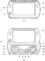
図2は、電子機器10の外観構成を示す。図2において、電子機器10は閉状態にある。図2(a)は、電子機器10の頂面図であり、図2(b)は、電子機器10の底面図である。下側筐体30の頂面には、左ボタン37a、右ボタン37bおよび音量ボタン38a、38bが設けられ、底面には、接続用端子39およびヘッドホン/マイク端子40が設けられる。接続用端子39は、外部の機器と接続するために用いられる。 FIG. 2 shows an external configuration of the
図3は、電子機器10の外観構成を示す。図3において、電子機器10は閉状態にある。図3(a)は、電子機器10の左側面図であり、図3(b)は、電子機器10の右側面図である。下側筐体30の左側面には、メディアカードスロット41が設けられ、右側面にはホールドスイッチ50が設けられる。 FIG. 3 shows an external configuration of the
電子機器10において、上側筐体20の前面に設けられた操作ボタン22、下側筐体30の前面に設けられた方向キー31、アナログパッド32、スタートボタン34、セレクトボタン35、操作ボタン36、下側筐体30の頂面に設けられた左ボタン37a、右ボタン37bは、ユーザにより操作される操作キーである。ホールドスイッチ50は、ユーザによりオフ位置とオン位置との間で動かされ、オン位置に動かされると、ユーザによる操作キーへの操作入力の受け付けが無効とされる。電子機器10が閉状態にある場合、下側筐体30の前面に設けられた操作キーは外部に露出しないが、操作ボタン22、左ボタン37a、右ボタン37bは、常に外部に露出している。そのためユーザは、電子機器10の利用を終了するときには、ホールドスイッチ50をオン位置に動かすことで、操作ボタン22、左ボタン37a、右ボタン37bのキー操作を無効化させ、操作キーの意図しない誤操作を回避することができる。 In the
電子機器10は携帯型ゲーム機であってよい。ゲーム機として利用する場合、ユーザは、電子機器10を開状態にして、ゲームアプリケーションを実行する。ディスプレイ23にはゲーム画像が表示され、ユーザは、電子機器10を把持しながら方向キー31や操作ボタン36などを操作して、ゲームを楽しむことができる。ゲームを終了すると、ユーザは、電子機器10を閉状態にする。電子機器10はバッテリ駆動であるため、電子機器10が閉状態になると、消費電力を低減させるために、動作モードを通常モードからスリープモードに切り替えて、省電力化を図ることが好ましい。 The
近年では、電子機器の多機能化が進んでおり、たとえば音楽再生機能が携帯電話機などの電子機器に組み込まれることが増えている。本実施例の電子機器10も、ゲーム実行機能だけでなく、音楽再生機能を有して構成されてもよい。電子機器10が音楽再生機器として利用される場合、その利用態様は、ゲーム機とは異なることが想定される。すなわち、ゲーム機として利用される場合、ユーザは電子機器10を把持しながら操作キーを操作するが、音楽再生機器として利用される場合には、ユーザは、電子機器10を把持するのではなく、カバンや衣服のポケットなどに電子機器10を入れて、イヤホンやヘッドホンなどを用いて音楽を聴く利用態様が想定される。 In recent years, electronic devices have become more multifunctional. For example, music playback functions are increasingly incorporated in electronic devices such as mobile phones. The
このように音楽再生機器として利用される場合には、電子機器10は閉状態にされるのが通常であると考えられるが、電子機器10を閉状態にしたときに、動作モードが常にスリープモードに移行すると、音楽再生アプリケーションも終了することになり、好ましくない。そこで本実施例の電子機器10は、ユーザの簡易なスイッチ操作により、スリープモードへの移行の有無を設定可能とする。 When used as a music playback device in this way, it is considered that the
図4は、電子機器10の内部構成を示す。電子機器10は、メインCPU100およびシステムコントローラ200を備える。メインCPU100およびシステムコントローラ200は、別個のチップに形成され、それぞれバッテリから異なる系統で電力供給を受ける。メインCPU100は、本体情報の設定や、アプリケーションの選択をユーザに行わせるためのメニュー画面を生成するメニュー処理部102と、アプリケーションを実行するアプリケーション処理部104を有する。また電子機器10は、ユーザにより設定された本体情報を保持する設定情報保持部202と、電子機器10の状態の遷移を検出する開閉検出部220を備える。 FIG. 4 shows an internal configuration of the
システムコントローラ200は、メインCPU100とは独立して、各種操作キーの状態検出機能、通信処理機能および電力制御機能を実行する。具体的にシステムコントローラ200は、操作入力受付部204、遷移情報受付部206、ホールド状態値受付部208、電力制御部210および通信処理部212を有する。 The
システムコントローラ200の機能は、CPU、メモリ、メモリにロードされたプログラムなどによって実現され、ここではそれらの連携によって実現される機能ブロックを描いている。したがってこれらの機能ブロックがハードウエアのみ、ソフトウエアのみ、またはそれらの組合せによっていろいろな形で実現できることは、当業者に理解されるところである。 The functions of the
上記したように、閉状態にある電子機器10では、音楽再生アプリケーションなどの実行中以外は、原則としてメインCPU100の動作モードをスリープモードに設定して、省電力化を実現することが好ましい。しかしながらユーザによっては、電子機器10が閉状態にあるときに、現在時刻情報などのディスプレイ表示を希望することもある。そこで本実施例の電子機器10では、閉状態にしたときの電子機器10の動作を、本体情報としてユーザに予め登録させることとしている。 As described above, in the
図5は、閉状態にしたときの電子機器10の動作を設定するための画面例を示す。メニュー処理部102は、ユーザが本体情報設定処理を行う際に、図5に示す設定画面を生成する。この設定画面においてユーザが、操作ボタン36bを押下すると、操作入力受付部204が、操作ボタン36bの押下入力を受け付け、メニュー処理部102に供給する。メニュー処理部102は、本体情報項目「閉状態にしたときの設定」に対して用意されている設定項目の選択画面を生成する。なお、図5に示す設定画面においては、設定項目の初期値として「標準」が選択された状態が示される。 FIG. 5 shows an example of a screen for setting the operation of the
図6は、設定項目の選択画面60を示す。選択画面60には、「標準」と「スリープモードにする」の2つの選択肢が示される。設定項目「標準」が選択されると、電子機器10が開状態から閉状態に遷移したときに、アプリケーション処理部104が、現在時刻情報を示す時計をディスプレイ23に表示するアプリケーションを実行する。設定項目「スリープモードにする」が選択されると、電子機器10が開状態から閉状態に遷移したときに、メインCPU100への電力供給を停止するスリープモードが実行される。なおスリープモードの実行時、電子機器10が閉状態から開状態に遷移すると、メインCPU100への電力供給が再開されて、メインCPU100がレジュームされる。ユーザにより選択された設定項目は、本体情報として設定情報保持部202に保持される。以下では、ユーザにより「スリープモードにする」が選択された場合について説明する。 FIG. 6 shows a setting
図4に戻り、システムコントローラ200において、遷移情報受付部206は、開閉検出部220から、電子機器10が開状態から閉状態に、または閉状態から開状態に状態遷移したことを示す遷移情報を受け付ける。上側筐体20および下側筐体30は、スライド機構によりスライド可能に連結されており、開閉検出部220は、スライド機構に設けられた磁気センサを有して構成されてもよい。開閉検出部220は、電子機器10が開状態から閉状態に遷移したとき、または閉状態から開状態に遷移したときに、その遷移したことを示す遷移情報を遷移情報受付部206に出力する。たとえば開閉検出部220は、開状態から閉状態に遷移したときには信号値0の遷移情報を、また閉状態から開状態に遷移したときには信号値1の遷移情報を遷移情報受付部206に出力してもよい。遷移情報受付部206は、開閉検出部220から遷移情報を受け付け、電子機器10が閉状態に遷移したか、または開状態に遷移したかを判定する。 Returning to FIG. 4, in the
なお、開閉検出部220は、開状態であるか閉状態であるかを示す状態情報を遷移情報受付部206に出力してもよい。たとえば開閉検出部220は、閉状態にあるときは状態値0を、開状態にあるときは状態値1を遷移情報受付部206に出力する。このとき遷移情報受付部206は、状態情報が変化したときに、状態遷移が生じたことを判定してもよい。この場合、開閉検出部220および遷移情報受付部206は、協働して、電子機器10の状態の遷移を検出する機能を実現する。 Note that the open /
電力制御部210は、遷移情報受付部206で受け付ける遷移情報または遷移情報受付部206による判定結果を監視する。設定情報保持部202において、閉状態にしたときに「スリープモードにする」ことを定めた本体情報が保持されており、開状態から閉状態への遷移が検出された場合に、電力制御部210は、原則としてメインCPU100の動作モードを通常モードからスリープモードに切り替える。なお、通常モードは、メインCPU100に電力を供給する動作モードであり、スリープモードは、メインCPU100への電力供給を停止する動作モードである。動作モードをスリープモードに設定することで、省電力化を実現できる。 The
以上は、電子機器10の基本電力制御であるが、本実施例の電子機器10においては、閉状態にしたときに「スリープモードにする」ことを定めた本体情報が設定情報保持部202に保持されている場合であっても、本体情報を変更することなく、開状態から閉状態への遷移が検出されてもユーザによる操作スイッチの操作状態に応じて、スリープモードへの移行を禁止する制御が行われる。 The above is the basic power control of the
ホールド状態値受付部208は、ホールドスイッチ50の状態値を受け付ける。ホールドスイッチ50の状態値は、ホールドスイッチ50のオン状態またはオフ状態を示す値である。なお、オン状態を示す状態値は、操作キーの操作入力の受け付けを無効にすることを操作入力受付部204に指示する信号である。ホールド状態値受付部208が、ホールドスイッチ50のオン状態を示す状態値を受け付けると、操作入力受付部204が、操作キーの操作入力の受け付けを無効にする。これにより、ユーザは、電子機器10に設けられた操作キーを有効に操作できないようになる。 The hold state
なおホールド状態値受付部208は、ホールドスイッチ50の状態値ではなく、ホールドスイッチ50の状態が切り替わったことを示す信号を受け付けてもよい。ホールドスイッチ50は、ユーザによりオン位置からオフ位置、またはオフ位置からオン位置に動かされたときに、切り替えられたことを示す切替情報をホールド状態値受付部208に出力する。ホールド状態値受付部208が、ホールドスイッチ50がオフ状態からオン状態に切り替えられたことを示す切替情報を受け付けると、操作入力受付部204が、操作キーの操作入力の受け付けを無効にする。 Note that the hold state
電力制御部210は、ホールドスイッチ50がオフ状態にある場合に、開閉検出部220および/または遷移情報受付部206にて開状態から閉状態への遷移が検出されると、メインCPU100の動作モードを通常モードからスリープモードに切り替える。一方、電力制御部210は、ホールドスイッチ50がオン状態にある場合に、開閉検出部220および/または遷移情報受付部206にて開状態から閉状態への遷移が検出されても、メインCPU100の動作モードを通常モードからスリープモードに切り替えず、通常モードを維持する。これにより、アプリケーション処理部104は、実行中のアプリケーションを、電子機器10が閉状態になっても継続して実行できる。 When the
ホールドスイッチ50がオン状態にある場合、操作入力受付部204は、操作キーの操作入力の受け付けを無効にするが、同様に、遷移情報受付部206も、開閉検出部220から出力される遷移情報の受け付けを無効にする。そのため電力制御部210は、開状態から閉状態に遷移した場合であっても、遷移情報の受け付けが無効にされることで、その遷移したことを認識しない。したがって電力制御部210は、開閉検出部220および/または遷移情報受付部206にて開状態から閉状態への遷移が検出されても、その遷移を認識しないことで、動作モードをスリープモードには切り替えず、通常モードを維持する電力制御を行う。 When the
以上説明した遷移情報受付部206が遷移情報の受け付けを無効にする処理とは別に、電力制御部210は、ホールド状態値受付部208で受け付ける状態値を監視してもよい。設定情報保持部202において、閉状態にしたときに「スリープモードにする」ことを定めた本体情報が保持されている場合であっても、電力制御部210は、開状態から閉状態への遷移が検出されたときに、ホールドスイッチ50がオン状態にあれば、メインCPU100の動作モードを通常モードからスリープモードに切り替えず、通常モードを維持するようにしてもよい。これにより、アプリケーション処理部104は、実行中のアプリケーションを、電子機器10が閉状態になっても継続して実行できる。 Apart from the process in which the transition
ホールドスイッチ50に、ユーザによる動作モードの設定機能を割り当てることで、電子機器10の資源を有効に利用できる。また、電子機器10を閉状態にしたときには、操作キーの操作を無効化することが好適な場合が多く、特に音楽再生アプリケーションにおいては、ユーザが操作キーを操作する場面も少ない。そのため、ホールドスイッチ50に動作モードの設定機能を割り当てることで、1回のホールドスイッチ50の操作で、操作キーの操作を無効化するとともに、スリープモードへの移行を禁止することができ、基本的にキー操作を必要としないアプリケーションに対して、簡易に好適な環境を提供することができる。 By assigning the operation mode setting function by the user to the
以上のように、本実施例の電子機器10では、電力制御部210が、ホールドスイッチ50がオン状態にある場合に、開状態から閉状態への遷移が検出されても、アプリケーション処理部104を含むメインCPU100の動作モードを通常モードからスリープモードに切り替えない。このように、本実施例の電子機器10では、閉状態にしたときに、実行していたアプリケーションをそのまま継続するか否かを、ユーザがホールドスイッチ50のオンオフ設定により簡易に制御できるという利点がある。 As described above, in the
なお、ホールドスイッチ50がオン状態にあるとき、メインCPU100は、閉状態であってもアプリケーションの実行を継続するが、電子機器10に設けられた操作キーの操作入力の受け付けは無効とされる。そのため、操作入力用のリモートコントローラを用意し、通信処理部212が、リモートコントローラからの操作入力を受け付けるようにしてもよい。これによりユーザは、音楽再生アプリケーションを自在に操作することができる。リモートコントローラの使用の可否については、アプリケーションごとに定められてよい。なお、このとき、ホールドスイッチ50をオフ状態にしても、電子機器10の状態遷移が生じるわけではないため、電力制御部210は、メインCPU100の動作モードをスリープモードに切り替えることはない。 When the
本実施例の電子機器10では、ホールドスイッチ50がオフ状態にあれば、開状態から閉状態に遷移すると、スリープモードに移行する。スリープモードの実行時、電子機器10が閉状態から開状態に遷移すると、メインCPU100への電力供給が再開されて、メインCPU100がレジュームされる。 In the
スリープモードの実行時に、ホールドスイッチ50がオフ位置からオン位置に動かされたときの電子機器10の動作について説明する。ホールドスイッチ50がオン状態にあれば、遷移情報受付部206は、遷移情報の受け付けを無効にする。そのため、電力制御部210は、電子機器10が閉状態から開状態に遷移しても、遷移情報の受け付けが無効にされることで、その遷移したことを認識しない。したがって電力制御部210は、開閉検出部220および/または遷移情報受付部206にて閉状態から開状態への遷移が検出されても、その遷移を認識しないことで、動作モードを通常モードには切り替えず、メインCPU100はレジュームされない。 An operation of the
図7は、メインCPU100のスリープモードへの移行制御を示すフローチャートである。上記したように、この制御フローでは、電子機器10を閉状態にしたときに、スリープモードに入ることを定めた本体情報が設定されていることを前提とする。遷移情報受付部206が、開閉検出部220からの遷移情報の到来を監視する(S10)。開閉検出部220から遷移情報が出力されなければ(S10のN)、本制御フローは実行されない。遷移情報受付部206が、開状態から閉状態に遷移したことを示す遷移情報を受け付けると(S10のY)、ホールドスイッチ50がオン状態にあるかオフ状態にあるかに応じて(S12)、遷移情報受付部206が、遷移情報の扱いを決定する。 FIG. 7 is a flowchart showing the transition control of the
遷移情報受付部206は、ホールドスイッチ50がオフ状態にあれば(S12のN)、遷移情報の受け付けを有効とし、電力制御部210は、メインCPU100の動作モードを通常モードからスリープモードに切り替える(S16)。一方、ホールドスイッチ50がオン状態にあれば(S12のY)、遷移情報受付部206は、遷移情報の受け付けを無効とし、電力制御部210は、メインCPU100の動作モードを通常モードからスリープモードに切り替えず、通常モードを維持する(S14)。以上により、メインCPU100の動作モードの制御が終了する。 If the
以上、本発明を実施例をもとに説明した。この実施例は例示であり、それらの各構成要素や各処理プロセスの組合せにいろいろな変形例が可能なこと、またそうした変形例も本発明の範囲にあることは当業者に理解されるところである。 In the above, this invention was demonstrated based on the Example. This embodiment is an exemplification, and it will be understood by those skilled in the art that various modifications can be made to the combination of each component and each processing process, and such modifications are also within the scope of the present invention. .
実施例では、主に、電子機器10を閉状態にしたときにスリープモードに入ることを定めた本体情報が設定されていた場合の、ホールドスイッチ50の操作状態に応じた電力制御について説明した。変形例では、電子機器10を閉状態にしたときに「標準」に入ることを定めた本体情報が設定されている場合に、アプリケーション処理部104が、ホールドスイッチ50の操作状態に応じてアプリケーションの実行を制御する。 In the embodiment, the power control according to the operation state of the
実施例に示したように、設定項目「標準」が選択されると、電子機器10が開状態から閉状態に遷移したときに、アプリケーション処理部104が、現在時刻情報を示す時計をディスプレイ23に表示するアプリケーションを実行する。変形例では、ホールドスイッチ50がオン状態にあると、電子機器10が開状態から閉状態に遷移しても、遷移情報受付部206が、遷移情報の受け付けを無効とすることで、アプリケーション処理部104が、アプリケーションを実行しないようにしてもよい。 As shown in the embodiment, when the setting item “standard” is selected, when the
また、電子機器10が開状態から閉状態に遷移して、アプリケーション処理部104が時計をディスプレイ23に表示するアプリケーションを実行しているときにホールドスイッチ50がオン状態にされると、電子機器10が閉状態から開状態に遷移しても、アプリケーション処理部104は、アプリケーションを実行し続けてもよい。遷移情報受付部206が遷移情報の受け付けを無効とすることで、アプリケーション処理部104が、閉状態から開状態への遷移を認識せず、時計をディスプレイ23に引き続き表示する。なお、このとき、ホールドスイッチ50がオン状態にあるため、操作キーのキー操作は無効とされるが、たとえば時刻合わせなど、時計の設定に必要な操作キーの操作に限っては、操作入力受付部204が、有効なものとして受け付けるようにしてもよい。 Further, when the
実施例では、ユーザが動作モード制御の設定を行う操作スイッチとしてホールドスイッチ50を利用したが、ホールドスイッチ50とは別に、ユーザが動作モード制御の設定を行うための操作スイッチが設けられてもよい。 In the embodiment, the
また、実施例では上側筐体20と下側筐体30とが並行に直進方向にスライド可能に連結される電子機器10を示したが、上側筐体20と下側筐体30とは、回転方向にスライド可能に連結されてもよい。 Moreover, although the upper housing | casing 20 and the lower housing | casing 30 showed the
10・・・電子機器、20・・・上側筐体、23・・・ディスプレイ、30・・・下側筐体、50・・・ホールドスイッチ、100・・・メインCPU、102・・・メニュー処理部、104・・・アプリケーション処理部、200・・・システムコントローラ、202・・・設定情報保持部、204・・・操作入力受付部、206・・・遷移情報受付部、208・・・ホールド状態値受付部、210・・・電力制御部、212・・・通信処理部、220・・・開閉検出部。DESCRIPTION OF
Claims (2)
Translated fromJapanese当該電子機器の状態の遷移を検出する開閉検出部と、
アプリケーションを実行するアプリケーション処理部と、
前記アプリケーション処理部の動作モードを設定する電力制御部と、
ユーザにより操作される操作スイッチと、を備え、
前記操作スイッチは、オン状態にされると、前記操作キーの操作入力の受け付けを無効にすることを指示するホールドスイッチであり、
前記電力制御部は、前記操作スイッチがオフ状態にある場合に、開状態から閉状態への遷移が検出されると、前記アプリケーション処理部の動作モードを通常モードからスリープモードに切り替え、前記操作スイッチがオン状態にある場合に、開状態から閉状態への遷移が検出されても、前記アプリケーション処理部の動作モードを通常モードからスリープモードに切り替えないことを特徴とする電子機器。An upper housing and a lower housing, wherein the upper housing and the lower housing are slidably coupled so that an operation key provided on the front surface of the lower housing is exposed to the outside. An electronic device capable of taking at least two states: a state and a closed state in which the operation keys are not exposed to the outside,
An open / close detection unit for detecting a state transition of the electronic device;
An application processing unit for executing the application;
A power control unit for setting an operation mode of the application processing unit;
An operation switch operated by a user,
When the operation switch is turned on, the operation switch is a hold switch that instructs to invalidate reception of an operation input of the operation key;
The power control unit switches the operation mode of the application processing unit from a normal mode to a sleep mode when a transition from an open state to a closed state is detected when the operation switch is in an off state, and the operation switch An electronic device characterized in that, when a transition from an open state to a closed state is detected when the device is in an on state, the operation mode of the application processing unit is not switched from the normal mode to the sleep mode.
Priority Applications (7)
| Application Number | Priority Date | Filing Date | Title |
|---|---|---|---|
| JP2009217882AJP4683397B2 (en) | 2009-09-18 | 2009-09-18 | Electronics |
| EP10816841.0AEP2472354A4 (en) | 2009-09-18 | 2010-08-25 | Electronic device |
| KR1020127009512AKR101503419B1 (en) | 2009-09-18 | 2010-08-25 | Electronic device |
| PCT/JP2010/005230WO2011033726A1 (en) | 2009-09-18 | 2010-08-25 | Electronic device |
| AU2010296787AAU2010296787B2 (en) | 2009-09-18 | 2010-08-25 | Electronic device |
| CN201080041268.XACN102498452B (en) | 2009-09-18 | 2010-08-25 | Electronic device |
| US13/394,592US8935554B2 (en) | 2009-09-18 | 2010-08-25 | Hand held electronic device with user controlled power saving feature |
Applications Claiming Priority (1)
| Application Number | Priority Date | Filing Date | Title |
|---|---|---|---|
| JP2009217882AJP4683397B2 (en) | 2009-09-18 | 2009-09-18 | Electronics |
Related Child Applications (1)
| Application Number | Title | Priority Date | Filing Date |
|---|---|---|---|
| JP2010287776ADivisionJP5291081B2 (en) | 2010-12-24 | 2010-12-24 | Electronics |
Publications (2)
| Publication Number | Publication Date |
|---|---|
| JP2011065584A JP2011065584A (en) | 2011-03-31 |
| JP4683397B2true JP4683397B2 (en) | 2011-05-18 |
Family
ID=43758341
Family Applications (1)
| Application Number | Title | Priority Date | Filing Date |
|---|---|---|---|
| JP2009217882AActiveJP4683397B2 (en) | 2009-09-18 | 2009-09-18 | Electronics |
Country Status (7)
| Country | Link |
|---|---|
| US (1) | US8935554B2 (en) |
| EP (1) | EP2472354A4 (en) |
| JP (1) | JP4683397B2 (en) |
| KR (1) | KR101503419B1 (en) |
| CN (1) | CN102498452B (en) |
| AU (1) | AU2010296787B2 (en) |
| WO (1) | WO2011033726A1 (en) |
Families Citing this family (12)
| Publication number | Priority date | Publication date | Assignee | Title |
|---|---|---|---|---|
| US9300342B2 (en)* | 2013-04-18 | 2016-03-29 | Apple Inc. | Wireless device with dynamically adjusted maximum transmit powers |
| US10564693B2 (en)* | 2013-07-10 | 2020-02-18 | Nintendo Co., Ltd. | Information processing system, information processing apparatus, information processing program, and method of controlling operation mode |
| JP6446827B2 (en)* | 2014-05-14 | 2019-01-09 | 株式会社島津製作所 | Analysis equipment |
| US9791490B2 (en) | 2014-06-09 | 2017-10-17 | Apple Inc. | Electronic device having coupler for tapping antenna signals |
| CN105116991A (en)* | 2015-08-26 | 2015-12-02 | 广东欧珀移动通信有限公司 | A terminal power saving method and device |
| CN105159436A (en)* | 2015-09-30 | 2015-12-16 | 新达通科技股份有限公司 | Industrial personal computer power on-off control apparatus and control method |
| CN105159437A (en)* | 2015-09-30 | 2015-12-16 | 联想(北京)有限公司 | Method and device for controlling electronic equipment |
| US20180026974A1 (en)* | 2016-07-21 | 2018-01-25 | Htc Corporation | Portable electric device and operating method therefor |
| CN108021219A (en) | 2016-11-03 | 2018-05-11 | 华为技术有限公司 | Control method of electronic device, device and electronic equipment |
| JP6792589B2 (en)* | 2018-04-06 | 2020-11-25 | レノボ・シンガポール・プライベート・リミテッド | Information processing equipment, control methods and programs |
| CN108594984A (en)* | 2018-04-24 | 2018-09-28 | 联想(北京)有限公司 | A kind of electronic equipment and control method |
| KR200491755Y1 (en)* | 2019-02-21 | 2020-06-04 | 이동현 | Apparatus for saving battery in mobile terminal |
Family Cites Families (25)
| Publication number | Priority date | Publication date | Assignee | Title |
|---|---|---|---|---|
| JPH08203200A (en)* | 1995-01-31 | 1996-08-09 | Sony Corp | Reproducing device |
| US5978923A (en)* | 1997-08-07 | 1999-11-02 | Toshiba America Information Systems, Inc. | Method and apparatus for a computer power management function including selective sleep states |
| JP2001005568A (en)* | 1999-06-25 | 2001-01-12 | Toshiba Corp | Portable computer |
| WO2002065303A1 (en)* | 2001-02-13 | 2002-08-22 | Fujitsu Limited | Network terminal having power saving mode |
| JP2003204383A (en)* | 2001-10-26 | 2003-07-18 | Nec Corp | Portable telephone |
| JP4051978B2 (en)* | 2002-03-27 | 2008-02-27 | 日本電気株式会社 | Mobile phone |
| JP4193411B2 (en) | 2002-04-26 | 2008-12-10 | 日本電気株式会社 | Mobile phone |
| US20040056651A1 (en)* | 2002-09-19 | 2004-03-25 | Daniele Marietta Bersana | System for detecting a flip-lid position of a personal electronic device |
| JP2004117436A (en)* | 2002-09-24 | 2004-04-15 | Fuji Xerox Co Ltd | Image forming apparatus |
| US20050044428A1 (en)* | 2003-08-21 | 2005-02-24 | Anthony Olson | Means for improving system operation by creating dependency between a power control and a latch |
| JP4213015B2 (en)* | 2003-10-31 | 2009-01-21 | 京セラ株式会社 | Mobile device |
| US7310740B2 (en)* | 2004-08-30 | 2007-12-18 | Dell Products L.P. | System and method for a configurable portable information handling system cover switch delay |
| JP4504147B2 (en)* | 2004-10-06 | 2010-07-14 | オリンパスイメージング株式会社 | Electronics |
| JP2007013302A (en)* | 2005-06-28 | 2007-01-18 | Konica Minolta Holdings Inc | Two-way communication system |
| KR100742590B1 (en)* | 2005-09-02 | 2007-08-02 | 엘지전자 주식회사 | Position fixing device of mobile communication terminal and mode switching method using same |
| AU2006347794A1 (en)* | 2006-08-29 | 2008-03-06 | Nokia Corporation | Electronic device with movable housing parts |
| JP2008055362A (en)* | 2006-09-01 | 2008-03-13 | Matsushita Electric Ind Co Ltd | Air cleaner |
| KR100800802B1 (en)* | 2006-09-26 | 2008-02-04 | 삼성전자주식회사 | Method and device for preventing malfunction of key input unit in portable terminal capable of attaching and detaching external case |
| JPWO2008059914A1 (en)* | 2006-11-17 | 2010-03-04 | アルプス電気株式会社 | Magnetic detector and electronic apparatus using the same |
| KR20100015800A (en)* | 2007-04-23 | 2010-02-12 | 소니 주식회사 | Electronic device, control method and program |
| TWI339792B (en)* | 2007-09-06 | 2011-04-01 | Inventec Corp | Power switch device |
| JP2009272996A (en)* | 2008-05-09 | 2009-11-19 | Toshiba Corp | Mobile terminal |
| TWI382733B (en)* | 2008-08-25 | 2013-01-11 | Htc Corp | Sliding electronic device |
| US8851992B2 (en)* | 2008-08-29 | 2014-10-07 | Disney Enterprises, Inc. | Music player for video game consoles and electronic devices operable in sleep or power-saving modes |
| US8190220B2 (en)* | 2009-01-30 | 2012-05-29 | Research In Motion Limited | Slider mechanism and configuration for a mobile communication device |
- 2009
- 2009-09-18JPJP2009217882Apatent/JP4683397B2/enactiveActive
- 2010
- 2010-08-25EPEP10816841.0Apatent/EP2472354A4/ennot_activeWithdrawn
- 2010-08-25AUAU2010296787Apatent/AU2010296787B2/enactiveActive
- 2010-08-25CNCN201080041268.XApatent/CN102498452B/enactiveActive
- 2010-08-25KRKR1020127009512Apatent/KR101503419B1/enactiveActive
- 2010-08-25WOPCT/JP2010/005230patent/WO2011033726A1/enactiveApplication Filing
- 2010-08-25USUS13/394,592patent/US8935554B2/enactiveActive
Also Published As
| Publication number | Publication date |
|---|---|
| AU2010296787B2 (en) | 2013-08-22 |
| EP2472354A1 (en) | 2012-07-04 |
| US8935554B2 (en) | 2015-01-13 |
| JP2011065584A (en) | 2011-03-31 |
| EP2472354A4 (en) | 2015-07-29 |
| CN102498452A (en) | 2012-06-13 |
| WO2011033726A1 (en) | 2011-03-24 |
| KR20120066037A (en) | 2012-06-21 |
| AU2010296787A1 (en) | 2012-04-05 |
| KR101503419B1 (en) | 2015-03-17 |
| US20120239955A1 (en) | 2012-09-20 |
| CN102498452B (en) | 2014-12-31 |
Similar Documents
| Publication | Publication Date | Title |
|---|---|---|
| JP4683397B2 (en) | Electronics | |
| KR101672212B1 (en) | Mobile terminal and operation method thereof | |
| TWI410824B (en) | Electronic device with the module integrating display unit and input unit | |
| JP4937677B2 (en) | Mobile terminal with touchpad | |
| KR101331346B1 (en) | Electronic apparatus | |
| CN101681185B (en) | Method and system for providing sensory information to devices and peripherals | |
| US8560020B2 (en) | Apparatus and method for controlling a touchscreen in a wireless terminal | |
| US20100181988A1 (en) | Method for reducing power consumption based on motion sensor and portable terminal using the same | |
| WO2004093419A1 (en) | Electronic device | |
| US20100182270A1 (en) | Electronic device with touch input assembly | |
| JP2007281864A (en) | Foldable mobile terminal, and control method thereof | |
| TWI411282B (en) | Communication device including one or more electrical control buttons in an upper housing part and method of operating the same | |
| JP2014235544A (en) | Electronic apparatus and input control method | |
| CN101472206A (en) | Earphone device | |
| WO2017053169A1 (en) | Electronic accessory device | |
| JP5582283B2 (en) | Portable information processing apparatus and control method thereof | |
| JP2014137753A (en) | Portable information terminal | |
| JP5291081B2 (en) | Electronics | |
| CN112230827B (en) | Interactive interface switching method and device and electronic equipment | |
| CN201087858Y (en) | Combined notebook computer | |
| KR20150000681A (en) | Mobile terminal and operation method thereof | |
| JP2010200045A (en) | Portable electronic apparatus | |
| CN201118652Y (en) | Ultra-thin dual-battery dual-mode operation wireless telephone device | |
| CN219285695U (en) | Stylus and electronic device system | |
| KR100703209B1 (en) | Mobile phone with Bluetooth mouse function |
Legal Events
| Date | Code | Title | Description |
|---|---|---|---|
| TRDD | Decision of grant or rejection written | ||
| A01 | Written decision to grant a patent or to grant a registration (utility model) | Free format text:JAPANESE INTERMEDIATE CODE: A01 | |
| FPAY | Renewal fee payment (event date is renewal date of database) | Free format text:PAYMENT UNTIL: 20140218 Year of fee payment:3 | |
| R150 | Certificate of patent or registration of utility model | Ref document number:4683397 Country of ref document:JP Free format text:JAPANESE INTERMEDIATE CODE: R150 Free format text:JAPANESE INTERMEDIATE CODE: R150 | |
| R250 | Receipt of annual fees | Free format text:JAPANESE INTERMEDIATE CODE: R250 | |
| R250 | Receipt of annual fees | Free format text:JAPANESE INTERMEDIATE CODE: R250 | |
| R250 | Receipt of annual fees | Free format text:JAPANESE INTERMEDIATE CODE: R250 | |
| R250 | Receipt of annual fees | Free format text:JAPANESE INTERMEDIATE CODE: R250 | |
| R250 | Receipt of annual fees | Free format text:JAPANESE INTERMEDIATE CODE: R250 | |
| R250 | Receipt of annual fees | Free format text:JAPANESE INTERMEDIATE CODE: R250 | |
| R250 | Receipt of annual fees | Free format text:JAPANESE INTERMEDIATE CODE: R250 | |
| R250 | Receipt of annual fees | Free format text:JAPANESE INTERMEDIATE CODE: R250 | |
| R250 | Receipt of annual fees | Free format text:JAPANESE INTERMEDIATE CODE: R250 |