JP4680935B2 - Transport container for cooling and holding frozen materials - Google Patents
Transport container for cooling and holding frozen materialsDownload PDFInfo
- Publication number
- JP4680935B2 JP4680935B2JP2006548225AJP2006548225AJP4680935B2JP 4680935 B2JP4680935 B2JP 4680935B2JP 2006548225 AJP2006548225 AJP 2006548225AJP 2006548225 AJP2006548225 AJP 2006548225AJP 4680935 B2JP4680935 B2JP 4680935B2
- Authority
- JP
- Japan
- Prior art keywords
- transport container
- coolant
- chamber
- container according
- container
- Prior art date
- Legal status (The legal status is an assumption and is not a legal conclusion. Google has not performed a legal analysis and makes no representation as to the accuracy of the status listed.)
- Expired - Fee Related
Links
Images


Classifications
- F—MECHANICAL ENGINEERING; LIGHTING; HEATING; WEAPONS; BLASTING
- F25—REFRIGERATION OR COOLING; COMBINED HEATING AND REFRIGERATION SYSTEMS; HEAT PUMP SYSTEMS; MANUFACTURE OR STORAGE OF ICE; LIQUEFACTION SOLIDIFICATION OF GASES
- F25D—REFRIGERATORS; COLD ROOMS; ICE-BOXES; COOLING OR FREEZING APPARATUS NOT OTHERWISE PROVIDED FOR
- F25D3/00—Devices using other cold materials; Devices using cold-storage bodies
- F25D3/02—Devices using other cold materials; Devices using cold-storage bodies using ice, e.g. ice-boxes
- F25D3/06—Movable containers
- F25D3/08—Movable containers portable, i.e. adapted to be carried personally
- A—HUMAN NECESSITIES
- A01—AGRICULTURE; FORESTRY; ANIMAL HUSBANDRY; HUNTING; TRAPPING; FISHING
- A01N—PRESERVATION OF BODIES OF HUMANS OR ANIMALS OR PLANTS OR PARTS THEREOF; BIOCIDES, e.g. AS DISINFECTANTS, AS PESTICIDES OR AS HERBICIDES; PEST REPELLANTS OR ATTRACTANTS; PLANT GROWTH REGULATORS
- A01N1/00—Preservation of bodies of humans or animals, or parts thereof
- A01N1/10—Preservation of living parts
- A01N1/14—Mechanical aspects of preservation; Apparatus or containers therefor
- A01N1/146—Non-refrigerated containers specially adapted for transporting or storing living parts whilst preserving
- A01N1/148—Non-refrigerated containers specially adapted for transporting or storing living parts whilst preserving with provisions specially adapted for transporting
- B—PERFORMING OPERATIONS; TRANSPORTING
- B01—PHYSICAL OR CHEMICAL PROCESSES OR APPARATUS IN GENERAL
- B01L—CHEMICAL OR PHYSICAL LABORATORY APPARATUS FOR GENERAL USE
- B01L7/00—Heating or cooling apparatus; Heat insulating devices
- B01L7/04—Heat insulating devices, e.g. jackets for flasks
- B—PERFORMING OPERATIONS; TRANSPORTING
- B01—PHYSICAL OR CHEMICAL PROCESSES OR APPARATUS IN GENERAL
- B01L—CHEMICAL OR PHYSICAL LABORATORY APPARATUS FOR GENERAL USE
- B01L3/00—Containers or dishes for laboratory use, e.g. laboratory glassware; Droppers
- B01L3/50—Containers for the purpose of retaining a material to be analysed, e.g. test tubes
- B01L3/508—Containers for the purpose of retaining a material to be analysed, e.g. test tubes rigid containers not provided for above
- B—PERFORMING OPERATIONS; TRANSPORTING
- B01—PHYSICAL OR CHEMICAL PROCESSES OR APPARATUS IN GENERAL
- B01L—CHEMICAL OR PHYSICAL LABORATORY APPARATUS FOR GENERAL USE
- B01L9/00—Supporting devices; Holding devices
- B01L9/06—Test-tube stands; Test-tube holders
- F—MECHANICAL ENGINEERING; LIGHTING; HEATING; WEAPONS; BLASTING
- F25—REFRIGERATION OR COOLING; COMBINED HEATING AND REFRIGERATION SYSTEMS; HEAT PUMP SYSTEMS; MANUFACTURE OR STORAGE OF ICE; LIQUEFACTION SOLIDIFICATION OF GASES
- F25D—REFRIGERATORS; COLD ROOMS; ICE-BOXES; COOLING OR FREEZING APPARATUS NOT OTHERWISE PROVIDED FOR
- F25D2201/00—Insulation
- F25D2201/10—Insulation with respect to heat
- F25D2201/14—Insulation with respect to heat using subatmospheric pressure
- F—MECHANICAL ENGINEERING; LIGHTING; HEATING; WEAPONS; BLASTING
- F25—REFRIGERATION OR COOLING; COMBINED HEATING AND REFRIGERATION SYSTEMS; HEAT PUMP SYSTEMS; MANUFACTURE OR STORAGE OF ICE; LIQUEFACTION SOLIDIFICATION OF GASES
- F25D—REFRIGERATORS; COLD ROOMS; ICE-BOXES; COOLING OR FREEZING APPARATUS NOT OTHERWISE PROVIDED FOR
- F25D2303/00—Details of devices using other cold materials; Details of devices using cold-storage bodies
- F25D2303/08—Devices using cold storage material, i.e. ice or other freezable liquid
- F25D2303/083—Devices using cold storage material, i.e. ice or other freezable liquid using cold storage material disposed in closed wall forming part of a container for products to be cooled
- F25D2303/0831—Devices using cold storage material, i.e. ice or other freezable liquid using cold storage material disposed in closed wall forming part of a container for products to be cooled the liquid is disposed in the space between the walls of the container
- F—MECHANICAL ENGINEERING; LIGHTING; HEATING; WEAPONS; BLASTING
- F25—REFRIGERATION OR COOLING; COMBINED HEATING AND REFRIGERATION SYSTEMS; HEAT PUMP SYSTEMS; MANUFACTURE OR STORAGE OF ICE; LIQUEFACTION SOLIDIFICATION OF GASES
- F25D—REFRIGERATORS; COLD ROOMS; ICE-BOXES; COOLING OR FREEZING APPARATUS NOT OTHERWISE PROVIDED FOR
- F25D2303/00—Details of devices using other cold materials; Details of devices using cold-storage bodies
- F25D2303/08—Devices using cold storage material, i.e. ice or other freezable liquid
- F25D2303/085—Compositions of cold storage materials
- F—MECHANICAL ENGINEERING; LIGHTING; HEATING; WEAPONS; BLASTING
- F25—REFRIGERATION OR COOLING; COMBINED HEATING AND REFRIGERATION SYSTEMS; HEAT PUMP SYSTEMS; MANUFACTURE OR STORAGE OF ICE; LIQUEFACTION SOLIDIFICATION OF GASES
- F25D—REFRIGERATORS; COLD ROOMS; ICE-BOXES; COOLING OR FREEZING APPARATUS NOT OTHERWISE PROVIDED FOR
- F25D2331/00—Details or arrangements of other cooling or freezing apparatus not provided for in other groups of this subclass
- F25D2331/80—Type of cooled receptacles
- F25D2331/804—Boxes
Landscapes
- Engineering & Computer Science (AREA)
- Health & Medical Sciences (AREA)
- Life Sciences & Earth Sciences (AREA)
- Chemical & Material Sciences (AREA)
- General Health & Medical Sciences (AREA)
- Mechanical Engineering (AREA)
- Zoology (AREA)
- Environmental Sciences (AREA)
- Dentistry (AREA)
- Combustion & Propulsion (AREA)
- Physics & Mathematics (AREA)
- Wood Science & Technology (AREA)
- Thermal Sciences (AREA)
- General Engineering & Computer Science (AREA)
- Clinical Laboratory Science (AREA)
- Chemical Kinetics & Catalysis (AREA)
- Packages (AREA)
- Sampling And Sample Adjustment (AREA)
- Agricultural Chemicals And Associated Chemicals (AREA)
Description
Translated fromJapanese本発明は、冷凍材料、特に冷凍された生物組織の標本又は培養細胞の冷却保持用輸送容器に関するものであり、断熱チャンバを取り囲む断熱材と、断熱チャンバ内に取り外し可能に配置されかつチャンバ内に冷凍材料を受け入れる内部容器と、相転移によって冷熱を発生する冷却剤とを含む輸送容器に関する。 The present invention relates to a cryocontainer, particularly a transport container for cooling and holding frozen biological tissue specimens or cultured cells, a heat insulating material surrounding the heat insulating chamber, a removably disposed heat insulating chamber, and the chamber. The present invention relates to a transport container including an inner container that receives a frozen material and a coolant that generates cold heat by phase transition.
古くから知られる材料の冷却保持方法は、材料を断熱容器の中に入れて、これによって材料が熱に曝露されるのを防ぐ方式である。しかし、特に輸送容器の場合には断熱材の壁面厚さに制限があり、従って断熱効果が限定される。このため、特に、比較的長い貯蔵又は輸送時間の場合、毀損的な温度上昇あるいは場合によっては冷凍材料の融解を回避するには、侵入する熱を対応する冷熱の生成によって確実に相殺する以外に選択肢はない。 A method of cooling and holding a material that has been known for a long time is a method in which a material is placed in an insulated container, thereby preventing the material from being exposed to heat. However, especially in the case of a transport container, the wall thickness of the heat insulating material is limited, and therefore the heat insulating effect is limited. For this reason, especially in the case of relatively long storage or transport times, in order to avoid detrimental temperature rises or in some cases melting of the frozen material, in addition to ensuring that the ingress heat is offset by the corresponding cold generation. There is no choice.
低温の冷却剤によって、流入する熱を相殺するのに必要な冷熱を供給する方式が知られている。この冷却剤は、寸法を相応に大きくした輸送容器の断熱チャンバ内に材料と共に入れられる。この方式においては、循環しなければならない媒体を含む冷却装置の経費は必要でない。冷却剤の固体→液体転移(融解熱)、液体→気体転移(蒸発熱)、あるいは固体→気体転移(昇華熱)の相転移を利用することによって、相転移の期間中の一定温度を達成することができるが、この期間は使用する冷却剤の量によって定まる。 There is known a system for supplying cold heat necessary for canceling inflowing heat using a low-temperature coolant. This coolant is placed with the material in an insulated chamber of the shipping container of correspondingly larger dimensions. In this manner, there is no need for the cost of a refrigeration system that includes media that must be circulated. Achieve constant temperature during the phase transition by utilizing the solid-to-liquid transition (heat of fusion), liquid-> gas transition (heat of evaporation), or solid-> gas transition (heat of sublimation) of the coolant This period can depend on the amount of coolant used.
輸送容器に用いられるこのような冷却剤の周知の例は、氷(水)、ドライアイス(二酸化炭素)及び液体窒素である。氷が、冷凍材料の冷却保持用に用いるには0℃という高すぎる融点を有しているのに対して、固体二酸化炭素の昇華温度及び液体窒素の沸騰温度は通例の冷凍材料の温度より遥かに低いので、冷凍材料の過度の冷却を避けるために、冷却剤と材料との間に断熱壁を設ける等の付加的な手段を講じて適正な温度管理を行わなければならない。しかし、この場合、特に、それぞれ気体相への相転移が生起するという事実があるので、比較的大容積の気体が生成し、それを外部に排出しなければならない。限られた空間ではこの点が問題となり、例えば、この輸送容器の航空機による輸送を一層難しくする。 Well known examples of such coolants used in transport containers are ice (water), dry ice (carbon dioxide) and liquid nitrogen. Ice has a melting point that is too high, 0 ° C. to be used for refrigeration of the frozen material, whereas the sublimation temperature of solid carbon dioxide and the boiling temperature of liquid nitrogen are much higher than the temperatures of conventional frozen materials. Therefore, in order to avoid excessive cooling of the frozen material, additional temperature measures must be taken such as providing a heat insulating wall between the coolant and the material. However, in this case, in particular, there is a fact that a phase transition to the gas phase occurs, so that a relatively large volume of gas must be generated and discharged to the outside. This is a problem in confined spaces, for example, making it more difficult to transport this transport container by aircraft.
本発明は、比較的小型で軽量であり、従って取り扱い易い輸送容器であって、気体がそれから放散されることなく、かつ、材料の過度の冷却を防止する手段を必要とすることなく、所定の輸送期間の間、冷凍材料を確実に所期の冷却温度に簡単な方法で保持する輸送容器を提供するという目的に基づいている。 The present invention is a transport container that is relatively small and lightweight, and therefore easy to handle, without any gas being released from it and without requiring means to prevent excessive cooling of the material. It is based on the object of providing a transport container that ensures that the frozen material is kept at the desired cooling temperature in a simple manner during the transport period.
本発明によれば、この目的は、材料用の少なくとも1つの冷却チャンバと、冷却チャンバから分離された少なくとも1つの冷却剤チャンバで冷却剤を含み恒久的に密封シールされる冷却剤チャンバとを設けること、温度範囲−15℃〜−100℃において固体/液体間相転移する冷却剤を設けること、及び、断熱材が、≦0.01W/mKの熱伝導率λを有する超断熱材であることによって実現される。 According to the present invention, this object provides at least one cooling chamber for the material and a coolant chamber that contains the coolant and is permanently hermetically sealed in at least one coolant chamber separated from the cooling chamber. Providing a coolant that undergoes a solid / liquid phase transition in the temperature range of −15 ° C. to −100 ° C. It is realized by.
相転移温度が好ましい−30℃〜−85℃の間にある水銀又は有機物質又は混合物質が冷却剤として考慮の対象になる。凝固した水銀の融点は約−39℃(大気圧において)である。この温度は、例えば、医学的状態(癌)診断のための蛋白質及びRNA分析用として送付される組織の標本又は培養細胞等の生物学的材料の冷却保持用として非常に適しており、過度の冷却による毀損を防止する。さらなる利点は、この冷却剤を用いた場合、気体も蒸気も発生せず、相転移の間に容積が事実上変化しない点にある。 Mercury or organic substances or mixed substances whose phase transition temperature is preferably between -30 ° C. and -85 ° C. are considered as coolants. The melting point of the solidified mercury is about −39 ° C. (at atmospheric pressure). This temperature is very suitable, for example, for cryopreservation of biological materials such as tissue specimens or cultured cells sent for protein and RNA analysis for medical conditions (cancer) diagnosis. Prevent damage due to cooling. A further advantage is that with this coolant, no gas or vapor is generated and the volume does not change substantially during the phase transition.
本発明による輸送容器の場合、冷却剤は、冷却剤チャンバのハウジング内又は内部容器内に触れられることなく残存したままである。輸送後に液体に戻された(使用済みの)水銀は、取り外し可能な冷却剤容器又は内部容器を例えば液体窒素に浸漬して冷凍することによる液体→固体の相転移によって、新しい冷却保持輸送操作用として再生することができる。 In the case of the transport container according to the invention, the coolant remains untouched in the housing of the coolant chamber or in the inner container. Mercury returned (used) to liquid after transport can be used for new cooled holding transport operations by a liquid-to-solid phase transition, for example by immersing a removable coolant container or inner container in liquid nitrogen and freezing. Can be played as.
本発明による輸送容器の好適な改良形態及び発展形態が従属請求項に提示される。また、これらは、輸送容器の特に簡単な製造及び取り扱いと、対応すべき輸送距離従って冷却時間に対する冷却能力の適応とに関するものである。 Preferred refinements and developments of the transport container according to the invention are presented in the dependent claims. They also relate to the particularly simple manufacture and handling of the transport container and the adaptation of the cooling capacity to the transport distance to be accommodated and thus to the cooling time.
以下、概略図に基づいて、本発明による輸送容器の実施例を詳細に説明する。 Hereinafter, based on the schematic, the Example of the transport container by this invention is described in detail.
図1及び2による輸送容器1は、円筒状に形成されており、同様に円筒状の内部容器2と、2つの同じく円筒状の付加的容器3、4とを同軸配置で含んでいる。この2つの付加的容器は、断熱チャンバ5内で内部容器2の上端と下端に配置される。断熱チャンバ5は、厚壁のカップ形状の断熱材6によって構成され、上端7の内側が段付き構造になっており、断熱チャンバ5を閉止するカバーの形の、対応する段付き構造の厚壁断熱閉止部材8を受け入れている。断熱材6は硬質の防護筒9によって被包されている。この防護筒9の両端にはそれぞれ外ねじが設けられ、ねじ付きカバー11及び12の対応する係合ねじ端部10と固くねじ止めされている。 The
断熱材6及び断熱閉止部材8は、きわめて低い熱伝導率λ、例えば0.002W/mKの熱伝導率を有する高品質の断熱材料から構成する。周知のこの断熱材料は、その卓越した断熱効果のために超断熱材とも呼称される。 The
内部容器2は図3に示される。それは、中空ハウジング又はカップ部分13と、それとねじ結合することができるねじ付きカバー14とを含む。カップ部分13には、同じくカップ形状の冷却剤チャンバ15と、中央の冷却チャンバ16とが形成され、この冷却チャンバ16がねじ付きカバー14によって閉止される。冷却チャンバ16が、冷却保持して輸送するべき材料17を受け入れる。図示の例では、この材料は、上端を閉止部品19で閉止された標本容器18の中の標本である。冷却剤チャンバ15には冷却剤15'(例えば水銀)を充填し、固体状態になるまで深冷する。冷却剤15'を注入し得るようにするため、カップ部分13の中央底部に、六角ソケットのねじストッパ21をねじ込むためのねじを有する充填開口20が設けられる。ねじストッパ21は、それをねじ込んだ時に、カップ部分13の底面の外側に窪み22が生じるような寸法のものとし、窪み22が生じるようにねじ込む。この底面の窪み22には、充填開口20を溶接して閉止する際に形成される溶接ビード23が溶着される。その結果、冷却剤チャンバ15は恒久的に密封シールされ、冷却剤15'の漏出を懸念する必要は全くない。 The
カップ部分13及びねじ付きカバー14は、圧縮負荷及び衝撃負荷を変形することなく吸収し得るように、及び、航空機の墜落等の極端な場合にも損傷や冷却剤(水銀)の漏出が確実に生じないようにするため、高強度の材料から製造される。内部容器2に適した材料は、例えば高級鋼、チタン又はチタン合金(TiAl5Sn2)であるが、これらは、高い強度を有するだけでなく、輸送重量を低減するための相対的な軽量性をも備えている。水銀よりも毒性が低い冷却剤の場合は、アルミニウム又は耐低温性プラスチック等の他の材料も考慮の対象になる。 The
図4によれば、付加的な容器3及び4も同様に中空円筒状に形成される。これは、冷却剤チャンバ24を有するが、冷却チャンバは備えていない。冷却剤チャンバ24には同様に冷却剤24'を充填する。図3の場合と同様に、付加的な容器3、4の中央底部には、それぞれ、充填開口25、ねじストッパ26を装備し、かつ溶接ビード27を溶着する。付加的容器3、4は、同様に上記の材料から製造することができる。 According to FIG. 4, the
図5は、付加的容器3、4の寸法の円筒状断熱ストッパ28を示す。この断熱ストッパ28は、輸送距離又は輸送時間が相応に短い場合に、内部容器2内の冷却剤15'によって材料17が輸送中十分に冷却保持されるならば、付加的容器3、4に代えて冷却チャンバ16の中に挿入することができる。 FIG. 5 shows a
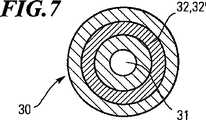
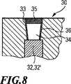
図6は、内部容器2の代わりに用いることができる内部容器30を示す。内部容器30は円筒状に形成され、その中心に円筒状の冷却チャンバ31を有する。この冷却チャンバ31は、内部容器30の上面から延びており、壁面の距離を置いて環状の冷却剤チャンバ32によって取り囲まれている。この冷却剤チャンバ32は、内部容器30の上端面及び下端面から壁面の距離を置いた範囲で止まっている。この場合も、冷却剤チャンバ32には冷却剤32'を充填する。冷却剤を注入するため、内部容器30の上端面に、冷却剤チャンバ32の方に向かって円錐状に僅かにテーパした充填開口33を形成する。この詳細が図8に示されている。冷却剤32'注入後、充填開口33を、同じく高級鋼又はチタン製のストッパ34によって閉止する。ストッパ34の上部で、充填開口33を溶接ビード35によって溶接閉止する。 FIG. 6 shows an
円錐状のストッパ34は、固定する前に強く過冷却して収縮させることによって、プレス嵌めとして適切に固定することができる。場合によっては、例えば銅等のアマルガム形成金属の円環状のシール材36を同時に装着することもできる。この方式はアマルガム(Hg−Cu合金)の形成を伴い、溶接ビード37による溶接閉止を省略することも可能になる。 The
図9は、同様に高級鋼又はチタン製とすることができる付加的容器37を示す。 FIG. 9 shows an
この付加的容器37も、冷却剤38'が充填される冷却剤チャンバ38を有しており、充填及び閉止操作用として図4又は図8に相当する形態が設けられる(図9には示されていない)。 This
付加的容器37は、その上面の中心に短いねじ付き突起39を備えており、このねじ付き突起39を、内部容器30の下面の中心の内ねじ付き窪み孔40にねじ込む。このため、付加的容器37を内部容器30と固く連結することができ、それによって容器30及び37間が密着して、良好な熱伝達を確保することができる。 The
さらに別の付加的容器37を、同様の方法で内部容器30の上部に連結することができる。冷却チャンバ31の上端面の内ねじ41がこの目的に用いられる。この内ねじ41は、冷却チャンバ31を閉止するねじストッパ42を六角のソケットレンチによってねじ込んだ後、さらに付加的容器37のねじ付き突起39をも内ねじ40の上端部の中にねじ込むことができるような軸方向の長さを有するものとする。 Yet another
図10は、高級鋼又はチタンの円筒状ブロック45を含む別の内部容器44を示す。この円筒状ブロック45には、上端面から延びる複数の穿孔が機械加工されている。図11に従って詳しく見ると、円筒に軸に沿って中心の穿孔が設けられ、その中心穿孔は同軸の穿孔の内側のリングに取り囲まれており、その内側のリングはさらに同軸の穿孔の外側のリングに囲繞されている。中心穿孔及び内側のリングの穿孔は冷却チャンバ46を形成し、従って、図3の標本容器18を全部で7個収納することができる。外側のリングの12個の穿孔は、それぞれ充填冷却剤47'を含む冷却剤チャンバ47を形成する。その上端においては、ねじ込みするか、あるいは、熱収縮によって挿入しプレス嵌めで保持することができるストッパ48によって、冷却剤チャンバ47を閉止する。 FIG. 10 shows another
冷却剤47'の漏出に対する追加的な安全対策が、リング状のカバー49を設けることによって実現される。このリング状のカバー49は、冷却剤チャンバ46の外側のリングを覆うものであり、図10に示すように、円筒状ブロック45に固く溶接される。 An additional safety measure against leakage of the coolant 47 ′ is realized by providing a ring-shaped
リング状のカバー49は内ねじ50を備えており、その中に、ディスク形状のねじ付きストッパ51がその外ねじ52によってねじ込まれ、最終的に上面においてリング状カバー49と同一面を形成する。冷却チャンバ46の終端部を形成するねじ付きストッパ51は、その上面側に、直径上に対置される2対の窪み孔53を有している。この窪み孔53は、ねじ込み又は取り外し時に、ピンレンチを差し込むためのものであり、互いに90°ずれている。リング状カバー49は、直径上に対置される2つの溝54を備えており、この2つの溝54が、ねじ付きストッパ51に高いねじ込み力を掛け得るようにするためのレンチ装着用の2つの平行な面を形成する。 The ring-shaped
図12によれば、円筒状ブロック56の形の付加的容器55も設けられる。これは、円筒状ブロック45と同様に、穿孔の外側のリングと内側のリングとを有しているが、中心穿孔を備えていない。この場合、2つの穿孔リング共、充填冷却剤57'を受け入れる冷却剤チャンバ57を形成する。冷却剤チャンバ57は、それぞれその上端においてストッパ58によって閉止される。このストッパ58は、図10のストッパ48と同様に、ねじ込みするか、あるいは、低温収縮によってプレス嵌めで固定することができる。 According to FIG. 12, an
円筒状ブロック56の上面の中心には、図10の内部容器44に連結するためのねじ付き突起59が設けられる。このため、円筒状ブロック45は、その底面の中心にねじ付き窪み孔60を備えている。ねじ付きストッパ51の上面の中心には、同等のねじ付き窪み孔61が設けられるので、図12の付加的容器55を、内部容器44の両端に連結することができる。 At the center of the upper surface of the
図13は、円錐状充填開口33閉止用の別の異なる円錐状ストッパ62を、まだ挿入前の状態において、図8に相当する拡大図で示している。ストッパ62は、円錐状ストッパ62を回転して充填開口33の中に摺り合わせするのに用いられる軸形状の付加部品63を有している。ストッパ62のこの嵌め合わせ完了後、ストッパ62に対して、図14に示すように、アマルガム形成金属の電解被膜64を被覆する。 FIG. 13 shows another different
被膜64を被覆したストッパ62を、続いて、好適には熱収縮を用いて充填開口33の中に固定すると、それが充填開口33の中にプレス嵌めによって保持される。この固定方式として、2つの変形形態を、好みによって考慮の対象にすることができる。すなわち、図15によれば、ストッパ62は、選定された寸法に対応して、皿穴への埋め込みの形で充填開口33の中に配置され、その上に溶接ビード65によって補足的な溶接閉止が行われる。仕上げ段階において、ストッパ62及び盛り上がった溶接ビード65は、平滑な機械仕上げ面66に仕上げられ、最終的には、図16に示すように、冷却剤チャンバ32を有するハウジング又は内部容器30の表面68と同一面になる。 When the
図17の代替方式によれば、ストッパ62が充填開口33を完全に一杯に塞いでいる。この場合、ストッパ62の突き出た部分、及び特に軸形状の全付加部品63は、図18のように、冷却剤チャンバ32を収納するハウジング又は内部容器30の表面68と最終的に同一面となる機械仕上げ面67に達するまで取り除かれる。 According to the alternative system of FIG. 17, the
図19による内部容器70は、図3に示す内部容器2と大部分一致している。円筒状のU字形内部容器70は、冷却剤71'が充填される冷却剤チャンバ71を有している。内壁72及び外壁73が、冷却剤71'を充填されかつ上記の方法で密封シールされた冷却剤チャンバ71の境界を定めるが、これは図19には示されていない。内壁72は、標本受け入れ用の冷却チャンバ74を取り囲んでいる。同様に超断熱材として構成される内部断熱材75が、冷却剤チャンバ71を囲繞している。この内部断熱材75を、ほぼ円筒状の壁面76が取り囲んでいる。冷却チャンバ74の上端部は、同様にカバー77によって閉止される。このカバー77は、断面表示されていないが、内壁72の上端にねじ込みされるストッパと、断熱効果を有するカバープレートとを備えている。内部容器70は、輸送時間及び保存時間が短いために冷却能力の増大が必要とされない場合には、上記に述べた形態において既に使用することが可能である。 The
内部容器70の特別な特徴は、それが、壁面76を取り囲みかつ冷却剤78'を含むジャケットチャンバ78を備えている点にある。この冷却剤78'は、冷却剤71'に比べてより高い温度で融解し、0℃〜−15℃の融点を有するものであり、ジャケット壁面79がそれを囲繞している。容器の外壁81を含む断熱ジャケット80がジャケットチャンバ78を取り囲む。同じく超断熱材として構成される断熱ジャケット80は、2つの部分から形成され、カップ形状の底部ジャケット部分82と、逆カップ形状のカバージャケット部分83とを含んでおり、カバー77、従って冷却チャンバ74を取り扱うために、カバージャケット部分83を取り外すことができる。図19に示す使用位置(輸送位置)においては、底部ジャケット部分82とカバージャケット部分83とが、その端面において互いに当接している。この場合、分割面の領域において、底部ジャケット部分82には狭い内側の段付きリング84が設けられ、上部のジャケット部分2には狭い外側の段付きリング85が設けられ、それが、内側の段付きリング84の上に係合している。これによって、分割面の領域において、熱の侵入が増大することが避けられる。 A special feature of the
図19により想定される、2つの異なる冷却剤71'及び78'を用いると、一般的に多少とも毒性があり従って危険である冷却剤71'の所要量を低減することができ、その代わりに、0℃〜15℃という若干高い温度範囲で融解/凝固する毒性の低い、あるいは毒性のない冷却剤(例えば水又はブライン)を使用し得るという利点が得られる。 The use of two different coolants 71 'and 78' envisioned by FIG. 19 can reduce the amount of coolant 71 'that is generally more or less toxic and therefore dangerous, instead The advantage is that a less toxic or non-toxic coolant (eg water or brine) that melts / solidifies in a slightly higher temperature range of 0 ° C. to 15 ° C. can be used.
輸送容器1は、例えば、1つ以上の冷凍された組織の標本を、それぞれ冷凍用の定置式冷却装置が設置されている1つの地点から別の地点に輸送するのに用いられる。従って、輸送操作は、冷却チェーンにおける中間リンクである。輸送は、例えばクーリエサービスによって行うことができるが、このサービスは、世界の遠隔地に対しても1日、2日又は3日という比較的短時間での輸送を保証している。さらに詳しく説明すると、ここで、以下のような手順に従う。 The
発送者は、最初に、内部容器2、30、44、70及び付加的容器3、4、37、55を、充填冷却剤15'、24'、32'、38'、47'、57'、71'、78'が完全に凝固するまで液体窒素で冷凍する。続いて、標本容器18内に入れられた標本17を冷却チャンバ16、31、46、74の中に挿入し、これをねじ付きカバー14、77あるいはねじ付きストッパ42、51で閉止する。次に、内部容器2、30、44、70、及び状況によって付加的容器3、4;37、55を断熱材6の中に収納する。内部容器30、44の場合には、例えば長い輸送距離で冷却能力を増大する必要がある場合、最初に、付加的容器37、55を内部容器30、44に固くねじ止めする。この後、断熱カバー8を載せ、ねじ付きカバー11を固くねじ止めして、極力遅滞なく輸送容器1を発送する。 The shipper first adds the
受取人は、逆の手順で、輸送容器1を開放し、標本17を含む標本容器18を取り出す。断熱材6の断熱チャンバ5内の温度、あるいは冷却チャンバ16、31、46、74内の温度は、例えば冷却剤の融点に相当する約−40℃でなければならないが、この温度は、受取人が、輸送容器1を開放する際に適切に測定する。もしこの温度でなければ、輸送時間が大幅に超過したために、充填冷却剤15'、24'、32'、38'、47'、57'、71'、78'の冷却能力が十分でなかったことになり、標本17は多分毀損されている可能性があるので、その場合は排除しなければならないことが結論付けられる。 The recipient opens the
上記の仕様に従って5cm厚さの超断熱材で装備された輸送容器1は、例えば、外径24cm、長さ24cmであり、従って取り扱い易く、クーリエサービスによる輸送に理想的に適している。 The
Claims (15)
Translated fromJapanesea)断熱チャンバ(5)を取り囲む熱伝導率λ≦0.005W/mKである超断熱材(6)と、
b)前記材料(17)用の少なくとも1つの冷却チャンバ(16、31、46、74)と、少なくとも1つの恒久的に密封シールされる冷却剤チャンバ(15、32、47、71)とを内部に有し、かつ前記断熱チャンバ(5)内に取り外し可能に配置される内部容器(2、30、44、70)と、
c)純粋な有機物質であり、温度範囲−100℃から−15℃において固体および液体状態間の相転移が生じ、かつ少なくとも50J/mlの融解熱を有し、固体/液体間相転移によって冷熱を発生する第1の冷却剤(15'、32'、47'、71')と、
を含む輸送容器。In a frozen material (17), in particular in a transport container for refrigerated holding of frozen biological tissue specimens or cultured cells,
a) superinsulation (6) with thermal conductivity λ ≦ 0.005 W / mK surrounding the thermal insulation chamber (5);
b) interior with at least one cooling chamber (16, 31, 46, 74) for said material (17) and at least one permanently hermetically sealed coolant chamber (15, 32, 47, 71) And an internal container (2, 30, 44, 70) removably disposed in the heat insulation chamber (5);
c) Pure organic material, which undergoes a phase transition between the solid and liquid states in the temperature range of −100 ° C. to −15 ° C., has a heat of fusion of at least 50 J / ml, and is cooled by the solid / liquid phase transition. A first coolant (15 ′, 32 ′, 47 ′, 71 ′) that generates
Including transport container.
Applications Claiming Priority (3)
| Application Number | Priority Date | Filing Date | Title |
|---|---|---|---|
| DE102004001351 | 2004-01-08 | ||
| DE102004032840 | 2004-07-06 | ||
| PCT/EP2005/000086WO2005066559A2 (en) | 2004-01-08 | 2005-01-07 | Transport container for keeping frozen material chilled |
Publications (2)
| Publication Number | Publication Date |
|---|---|
| JP2007523013A JP2007523013A (en) | 2007-08-16 |
| JP4680935B2true JP4680935B2 (en) | 2011-05-11 |
Family
ID=34751375
Family Applications (1)
| Application Number | Title | Priority Date | Filing Date |
|---|---|---|---|
| JP2006548225AExpired - Fee RelatedJP4680935B2 (en) | 2004-01-08 | 2005-01-07 | Transport container for cooling and holding frozen materials |
Country Status (6)
| Country | Link |
|---|---|
| US (1) | US20070210090A1 (en) |
| EP (1) | EP1704374A2 (en) |
| JP (1) | JP4680935B2 (en) |
| CN (1) | CN100594347C (en) |
| DE (1) | DE112005000154A5 (en) |
| WO (1) | WO2005066559A2 (en) |
Cited By (1)
| Publication number | Priority date | Publication date | Assignee | Title |
|---|---|---|---|---|
| KR200491161Y1 (en) | 2018-12-14 | 2020-04-24 | 대한민국 | Liquid nitrogen housing for straws freezing of sperm |
Families Citing this family (106)
| Publication number | Priority date | Publication date | Assignee | Title |
|---|---|---|---|---|
| DE102006032435A1 (en)* | 2006-07-13 | 2008-01-17 | Sixt, Bernhard, Dr. | Transport container for keeping refrigerated frozen goods |
| KR101486407B1 (en)* | 2006-07-28 | 2015-01-26 | 마퍼 리쏘그라피 아이피 비.브이. | Lithography system, method of heat dissipation and frame |
| EP2142431A4 (en)* | 2007-05-04 | 2014-06-18 | Entropy Solutions Inc | Package having phase change materials and method of use in transport of temperature sensitive payload |
| US8211516B2 (en) | 2008-05-13 | 2012-07-03 | Tokitae Llc | Multi-layer insulation composite material including bandgap material, storage container using same, and related methods |
| US8887944B2 (en) | 2007-12-11 | 2014-11-18 | Tokitae Llc | Temperature-stabilized storage systems configured for storage and stabilization of modular units |
| US20090145912A1 (en)* | 2007-12-11 | 2009-06-11 | Searete Llc, A Limited Liability Corporation Of The State Of Delaware | Temperature-stabilized storage containers |
| US20110127273A1 (en) | 2007-12-11 | 2011-06-02 | TOKITAE LLC, a limited liability company of the State of Delaware | Temperature-stabilized storage systems including storage structures configured for interchangeable storage of modular units |
| US9205969B2 (en)* | 2007-12-11 | 2015-12-08 | Tokitae Llc | Temperature-stabilized storage systems |
| US8485387B2 (en) | 2008-05-13 | 2013-07-16 | Tokitae Llc | Storage container including multi-layer insulation composite material having bandgap material |
| US9140476B2 (en) | 2007-12-11 | 2015-09-22 | Tokitae Llc | Temperature-controlled storage systems |
| US9174791B2 (en) | 2007-12-11 | 2015-11-03 | Tokitae Llc | Temperature-stabilized storage systems |
| US8215835B2 (en) | 2007-12-11 | 2012-07-10 | Tokitae Llc | Temperature-stabilized medicinal storage systems |
| WO2009143364A1 (en)* | 2008-05-21 | 2009-11-26 | Winterlab Limited | Apparatus and method for using a brine solution to freeze biopsy material |
| US9372016B2 (en) | 2013-05-31 | 2016-06-21 | Tokitae Llc | Temperature-stabilized storage systems with regulated cooling |
| US9447995B2 (en) | 2010-02-08 | 2016-09-20 | Tokitac LLC | Temperature-stabilized storage systems with integral regulated cooling |
| DE102010028769A1 (en) | 2010-05-07 | 2011-11-10 | Pvt Probenverteiltechnik Gmbh | System for transporting containers between different stations and container carriers |
| CN101849535B (en)* | 2010-05-24 | 2013-04-17 | 中国水产科学研究院黄海水产研究所 | Portable fish sperm frozen cooling device |
| US20110308271A1 (en) | 2010-06-18 | 2011-12-22 | Biocision, Inc. | Specimen freezing rate regulator device |
| DK2583078T3 (en)* | 2010-06-18 | 2024-10-07 | Biocision Inc | Apparatus for regulating the freezing rate of samples |
| US8439221B2 (en) | 2010-11-15 | 2013-05-14 | Troy M. Davis | Beverage container with chill sleeve |
| CN102246743B (en)* | 2011-04-20 | 2013-07-10 | 中国人民解放军第三军医大学 | Biological tissue cryopreservation device |
| EP2589966A1 (en) | 2011-11-04 | 2013-05-08 | Roche Diagnostics GmbH | Laboratory sample distribution system and corresponding method of operation |
| EP2589968A1 (en) | 2011-11-04 | 2013-05-08 | Roche Diagnostics GmbH | Laboratory sample distribution system, laboratory system and method of operating |
| EP2589967A1 (en) | 2011-11-04 | 2013-05-08 | Roche Diagnostics GmbH | Laboratory sample distribution system and corresponding method of operation |
| CN103112661A (en)* | 2012-12-11 | 2013-05-22 | 樊荣 | Portable refrigerating barrel |
| CN103190393B (en)* | 2013-04-09 | 2015-05-13 | 上海安久生物科技有限公司 | Biological sample vitrification carrier and application thereof |
| US9913777B2 (en) | 2013-05-16 | 2018-03-13 | Sandy Wengreen | Storage systems and methods for medicines |
| US9877894B2 (en) | 2013-05-16 | 2018-01-30 | Sandy Wengreen | Storage systems and methods for medicines |
| US9707156B2 (en) | 2013-05-16 | 2017-07-18 | Sandy Wengreen | Storage systems and methods for medicines |
| US20160262979A1 (en)* | 2013-05-16 | 2016-09-15 | Sandy Wengreen | Storage systems and methods for medicines |
| US10588820B2 (en) | 2013-05-16 | 2020-03-17 | Sandy Wengreen | Storage systems and methods for medicines |
| US9151531B2 (en)* | 2013-05-16 | 2015-10-06 | Sandy Wengreen | Storage systems and methods for medicines |
| US9844782B2 (en)* | 2013-06-21 | 2017-12-19 | Coldblock Technologies Inc. | Systems and methods for preparing samples for chemical analysis using a cooled digestion zone |
| CN103548815B (en)* | 2013-11-18 | 2015-06-10 | 王意 | Programmed cell freezing box with direct-in liquid nitrogen |
| DE102014202838B3 (en) | 2014-02-17 | 2014-11-06 | Roche Pvt Gmbh | Transport device, sample distribution system and laboratory automation system |
| DE102014202843B3 (en) | 2014-02-17 | 2014-11-06 | Roche Pvt Gmbh | Transport device, sample distribution system and laboratory automation system |
| CN103848101A (en)* | 2014-03-14 | 2014-06-11 | 杜海兵 | Medicine cold chain box |
| EP2927168A1 (en)* | 2014-03-31 | 2015-10-07 | Roche Diagniostics GmbH | Transport device, sample distribution system and laboratory automation system |
| EP2927625A1 (en) | 2014-03-31 | 2015-10-07 | Roche Diagniostics GmbH | Sample distribution system and laboratory automation system |
| EP2927167B1 (en) | 2014-03-31 | 2018-04-18 | F. Hoffmann-La Roche AG | Dispatch device, sample distribution system and laboratory automation system |
| EP2927163B1 (en) | 2014-03-31 | 2018-02-28 | Roche Diagnostics GmbH | Vertical conveyor, sample distribution system and laboratory automation system |
| EP2927695B1 (en) | 2014-03-31 | 2018-08-22 | Roche Diagniostics GmbH | Sample distribution system and laboratory automation system |
| ES2960772T3 (en)* | 2014-06-11 | 2024-03-06 | Rmb Products Inc | Rigid fluid container with phase change capability with recesses to aid handling |
| EP2957914B1 (en) | 2014-06-17 | 2018-01-03 | Roche Diagnostics GmbH | Laboratory sample distribution system and laboratory automation system |
| FR3023714A1 (en)* | 2014-07-18 | 2016-01-22 | Lab Francais Du Fractionnement | INNOVATIVE THERAPY DRUG PACKAGING |
| EP2977766A1 (en) | 2014-07-24 | 2016-01-27 | Roche Diagniostics GmbH | Laboratory sample distribution system and laboratory automation system |
| EP2995580A1 (en) | 2014-09-09 | 2016-03-16 | Roche Diagniostics GmbH | Laboratory sample distribution system and laboratory automation system |
| EP2995960B1 (en) | 2014-09-09 | 2020-07-15 | Roche Diagniostics GmbH | Laboratory sample distribution system and method for calibrating magnetic sensors |
| US9952242B2 (en) | 2014-09-12 | 2018-04-24 | Roche Diagnostics Operations, Inc. | Laboratory sample distribution system and laboratory automation system |
| EP2995958A1 (en) | 2014-09-15 | 2016-03-16 | Roche Diagniostics GmbH | Method of operating a laboratory sample distribution system, laboratory sample distribution system and laboratory automation system |
| EP3006943B1 (en) | 2014-10-07 | 2020-04-22 | Roche Diagniostics GmbH | Module for a laboratory sample distribution system, laboratory sample distribution system and laboratory automation system |
| EP3016116A1 (en) | 2014-11-03 | 2016-05-04 | Roche Diagniostics GmbH | Printed circuit board arrangement, coil for a laboratory sample distribution system, laboratory sample distribution system and laboratory automation system |
| EP3070479B1 (en) | 2015-03-16 | 2019-07-03 | Roche Diagniostics GmbH | Transport carrier, laboratory cargo distribution system and laboratory automation system |
| EP3073270B1 (en) | 2015-03-23 | 2019-05-29 | Roche Diagniostics GmbH | Laboratory sample distribution system and laboratory automation system |
| EP3095739A1 (en) | 2015-05-22 | 2016-11-23 | Roche Diagniostics GmbH | Method of operating a laboratory sample distribution system, laboratory sample distribution system and laboratory automation system |
| EP3096145B1 (en) | 2015-05-22 | 2019-09-04 | Roche Diagniostics GmbH | Method of operating a laboratory automation system and laboratory automation system |
| EP3096146A1 (en) | 2015-05-22 | 2016-11-23 | Roche Diagniostics GmbH | Method of operating a laboratory sample distribution system, laboratory sample distribution system and laboratory automation system |
| EP3112874A1 (en) | 2015-07-02 | 2017-01-04 | Roche Diagnostics GmbH | Storage module, method of operating a laboratory automation system and laboratory automation system |
| EP3121603A1 (en) | 2015-07-22 | 2017-01-25 | Roche Diagnostics GmbH | Sample container carrier, laboratory sample distribution system and laboratory automation system |
| JP6836235B2 (en)* | 2015-08-11 | 2021-02-24 | 株式会社ジェイ・エム・エス | Cell transport container |
| EP3139175B1 (en) | 2015-09-01 | 2021-12-15 | Roche Diagnostics GmbH | Laboratory cargo distribution system, laboratory automation system and method of operating a laboratory cargo distribution system |
| EP3153867B1 (en) | 2015-10-06 | 2018-11-14 | Roche Diagniostics GmbH | Method of configuring a laboratory automation system, laboratory sample distribution system and laboratory automation system |
| EP3153866A1 (en) | 2015-10-06 | 2017-04-12 | Roche Diagnostics GmbH | Method of determining a handover position and laboratory automation system |
| WO2017062692A1 (en) | 2015-10-06 | 2017-04-13 | Cold Chain Technologies,Inc. | Thermally insulated shipping system for pallet-sized payload, methods of making and using the same, and kit for use therein |
| EP3156352B1 (en) | 2015-10-13 | 2019-02-27 | Roche Diagniostics GmbH | Laboratory sample distribution system and laboratory automation system |
| EP3156353B1 (en) | 2015-10-14 | 2019-04-03 | Roche Diagniostics GmbH | Method of rotating a sample container carrier, laboratory sample distribution system and laboratory automation system |
| KR102703913B1 (en)* | 2015-12-09 | 2024-09-09 | 메디칸(주) | Refrigeration equipment and refrigeration cell comprises a cryogenic storage container |
| DE202016001097U1 (en)* | 2016-01-28 | 2017-05-02 | Va-Q-Tec Ag | Transport container system |
| EP3211429A1 (en) | 2016-02-26 | 2017-08-30 | Roche Diagnostics GmbH | Transport device having a tiled driving surface |
| EP3211428A1 (en) | 2016-02-26 | 2017-08-30 | Roche Diagnostics GmbH | Transport device unit for a laboratory sample distribution system |
| EP3211430A1 (en) | 2016-02-26 | 2017-08-30 | Roche Diagnostics GmbH | Transport device with base plate modules |
| CN109196363A (en) | 2016-06-03 | 2019-01-11 | 豪夫迈·罗氏有限公司 | Laboratory sample distribution system and laboratory automation system |
| EP3255519B1 (en) | 2016-06-09 | 2019-02-20 | Roche Diagniostics GmbH | Laboratory sample distribution system and method of operating a laboratory sample distribution system |
| EP3260867A1 (en) | 2016-06-21 | 2017-12-27 | Roche Diagnostics GmbH | Method of setting a handover position and laboratory automation system |
| MX2016008614A (en)* | 2016-06-29 | 2017-12-28 | Univ Nacional Autónoma De Mexico | Device for the thermal protection and transport of biomacromolecules. |
| JP6752350B2 (en) | 2016-08-04 | 2020-09-09 | エフ.ホフマン−ラ ロシュ アーゲーF. Hoffmann−La Roche Aktiengesellschaft | Laboratory sample distribution system and laboratory automation system |
| USD804807S1 (en) | 2016-09-22 | 2017-12-12 | Sandy Wengreen | Insulated container |
| EP3330717B1 (en) | 2016-12-01 | 2022-04-06 | Roche Diagnostics GmbH | Laboratory sample distribution system and laboratory automation system |
| EP3343232B1 (en) | 2016-12-29 | 2021-09-15 | Roche Diagnostics GmbH | Laboratory sample distribution system and laboratory automation system |
| CN106966060A (en)* | 2016-12-29 | 2017-07-21 | 浙江工商大学 | A kind of cold-storage express delivery box structure |
| EP3355065B1 (en) | 2017-01-31 | 2021-08-18 | Roche Diagnostics GmbH | Laboratory sample distribution system and laboratory automation system |
| EP3357842B1 (en) | 2017-02-03 | 2022-03-23 | Roche Diagnostics GmbH | Laboratory automation system |
| JP6881710B2 (en)* | 2017-03-28 | 2021-06-02 | 国立研究開発法人宇宙航空研究開発機構 | Insulation container and heat and cold insulation device using it |
| EP3410123B1 (en) | 2017-06-02 | 2023-09-20 | Roche Diagnostics GmbH | Method of operating a laboratory sample distribution system, laboratory sample distribution system and laboratory automation system |
| EP3428653B1 (en) | 2017-07-13 | 2021-09-15 | Roche Diagnostics GmbH | Method of operating a laboratory sample distribution system, laboratory sample distribution system and laboratory automation system |
| EP3456415B1 (en) | 2017-09-13 | 2021-10-20 | Roche Diagnostics GmbH | Sample container carrier, laboratory sample distribution system and laboratory automation system |
| EP3457144B1 (en) | 2017-09-13 | 2021-10-20 | Roche Diagnostics GmbH | Sample container carrier, laboratory sample distribution system and laboratory automation system |
| EP3537159B1 (en) | 2018-03-07 | 2022-08-31 | Roche Diagnostics GmbH | Method of operating a laboratory sample distribution system, laboratory sample distribution system and laboratory automation system |
| EP3540443B1 (en) | 2018-03-16 | 2023-08-30 | Roche Diagnostics GmbH | Laboratory system, laboratory sample distribution system and laboratory automation system |
| US10722427B2 (en) | 2018-03-29 | 2020-07-28 | Simon Charles Cantor | Hermetically sealable case for medical device and medicine |
| CN109160083A (en)* | 2018-09-27 | 2019-01-08 | 佛山科学技术学院 | A kind of laboratory sample transport save set |
| GB201917625D0 (en)* | 2019-12-03 | 2020-01-15 | Asymptote Ltd | Container sterilising apparatus and method |
| US11920862B2 (en)* | 2019-12-19 | 2024-03-05 | Praxair Technology, Inc. | Methods and apparatuses for using dry ice containers |
| US12127555B2 (en)* | 2020-04-08 | 2024-10-29 | Biolife Solutions, Inc. | Shock absorbing device to protect cryopreserved biological material |
| EP3925911B1 (en) | 2020-06-19 | 2023-05-24 | Roche Diagnostics GmbH | Laboratory sample distribution system and corresponding method of operation |
| EP3940388B1 (en) | 2020-07-15 | 2024-04-10 | Roche Diagnostics GmbH | Laboratory sample distribution system and method for operating the same |
| CN112167242B (en)* | 2020-09-24 | 2022-03-25 | 清华大学 | No active cooling low temperature storage and transportation device based on multilayer phase change material |
| WO2022094714A1 (en)* | 2020-11-05 | 2022-05-12 | Acorn Biolabs, Inc. | Temperature-controlled system for the collection and/or transportation of living and/or temperature-sensitive material |
| EP4001923B1 (en) | 2020-11-23 | 2024-06-05 | Roche Diagnostics GmbH | Laboratory sample distribution system and laboratory automation system |
| CN114594124A (en)* | 2020-12-07 | 2022-06-07 | 中国科学院大连化学物理研究所 | A liquid sample cell with high temperature resistance and good sealing |
| US11747356B2 (en) | 2020-12-21 | 2023-09-05 | Roche Diagnostics Operations, Inc. | Support element for a modular transport plane, modular transport plane, and laboratory distribution system |
| KR102276406B1 (en)* | 2020-12-23 | 2021-07-12 | 천성태 | Storage device for specimen ampoule |
| CA3111955A1 (en)* | 2021-03-12 | 2022-09-12 | Proprietect L.P. | Composite container |
| US11602486B2 (en)* | 2021-06-29 | 2023-03-14 | Daniel Singh | Device for chilling insulin in a travel mug |
| DE102022212394A1 (en) | 2022-11-21 | 2024-05-23 | dot.COOL Group Inc. | VACUUM CONTAINER, METHOD FOR MANUFACTURING THE SAME AND EVACUATION MODULE |
| CN117007210A (en)* | 2023-07-21 | 2023-11-07 | 浙江省计量科学研究院 | Liquid nitrogen constant temperature detector |
Family Cites Families (17)
| Publication number | Priority date | Publication date | Assignee | Title |
|---|---|---|---|---|
| US52269A (en)* | 1866-01-30 | Improvement in bottle-stoppers | ||
| US1771186A (en)* | 1928-06-20 | 1930-07-22 | Mock Hugo | Serving element for electric refrigerators |
| GB1004791A (en)* | 1963-06-19 | 1965-09-15 | Salterpak Ltd | Improvements relating to thermally-insulated cases |
| US3858410A (en)* | 1973-09-24 | 1975-01-07 | Daniel H Drake | Dental material mixing holder and cooler |
| US5355684A (en)* | 1992-04-30 | 1994-10-18 | Guice Walter L | Cryogenic shipment or storage system for biological materials |
| CN2199086Y (en)* | 1994-06-04 | 1995-05-31 | 徐松培 | Device for transporting refrigerated goods |
| AU7720596A (en)* | 1995-11-09 | 1997-05-29 | Aspen Systems, Inc. | Flexible aerogel superinsulation and its manufacture |
| US5895561A (en)* | 1996-01-17 | 1999-04-20 | Kennecott Utah Copper Corporation | Method of sealing cooling blocks using electrodeposited metal |
| JP2710606B2 (en)* | 1996-02-29 | 1998-02-10 | 耀明 蔡 | Cooling retention media for cooling cups |
| US6467299B1 (en)* | 1996-08-30 | 2002-10-22 | Triple Ccc Cc | Container for a vial or ampoule |
| NL1005375C1 (en)* | 1997-02-26 | 1998-08-28 | Kombo Publishing B V | Chilled dish for presentation of e.g. perishable cocktail snacks |
| US5934099A (en)* | 1997-07-28 | 1999-08-10 | Tcp/Reliable Inc. | Temperature controlled container |
| US6032481A (en)* | 1997-08-26 | 2000-03-07 | Mosby; Sharon D. | Thermoregulating container |
| US6209343B1 (en)* | 1998-09-29 | 2001-04-03 | Life Science Holdings, Inc. | Portable apparatus for storing and/or transporting biological samples, tissues and/or organs |
| US6119465A (en)* | 1999-02-10 | 2000-09-19 | Mullens; Patrick L. | Shipping container for storing materials at cryogenic temperatures |
| US6446461B1 (en)* | 2001-02-20 | 2002-09-10 | David L. Williams, Jr. | Beverage cooler |
| FR2840289A1 (en)* | 2002-05-29 | 2003-12-05 | Centre Nat Rech Scient | PACKAGING BOX FOR BIOLOGICAL PRODUCTS AND THE LIKE |
- 2005
- 2005-01-07JPJP2006548225Apatent/JP4680935B2/ennot_activeExpired - Fee Related
- 2005-01-07WOPCT/EP2005/000086patent/WO2005066559A2/enactiveApplication Filing
- 2005-01-07DEDE200511000154patent/DE112005000154A5/ennot_activeWithdrawn
- 2005-01-07EPEP05700741Apatent/EP1704374A2/ennot_activeWithdrawn
- 2005-01-07USUS10/585,378patent/US20070210090A1/ennot_activeAbandoned
- 2005-01-07CNCN200580002196Apatent/CN100594347C/ennot_activeExpired - Fee Related
Cited By (1)
| Publication number | Priority date | Publication date | Assignee | Title |
|---|---|---|---|---|
| KR200491161Y1 (en) | 2018-12-14 | 2020-04-24 | 대한민국 | Liquid nitrogen housing for straws freezing of sperm |
Also Published As
| Publication number | Publication date |
|---|---|
| EP1704374A2 (en) | 2006-09-27 |
| JP2007523013A (en) | 2007-08-16 |
| DE112005000154A5 (en) | 2007-06-21 |
| CN101124444A (en) | 2008-02-13 |
| WO2005066559A3 (en) | 2005-11-10 |
| WO2005066559A2 (en) | 2005-07-21 |
| US20070210090A1 (en) | 2007-09-13 |
| CN100594347C (en) | 2010-03-17 |
Similar Documents
| Publication | Publication Date | Title |
|---|---|---|
| JP4680935B2 (en) | Transport container for cooling and holding frozen materials | |
| JP7005095B2 (en) | Shipping container | |
| US4357809A (en) | Cooling arrangement including a gel | |
| US6209343B1 (en) | Portable apparatus for storing and/or transporting biological samples, tissues and/or organs | |
| US1369367A (en) | Cooling-container | |
| EP3604476B1 (en) | Cold storage material composition, method for using cold storage material composition, cold storage material and transport container | |
| WO2008006558A3 (en) | Transport container for maintaining the temperature of frozen goods | |
| JP2007118972A (en) | Constant temperature cool box and constant temperature cool method | |
| NO337527B1 (en) | Method and apparatus for ensuring maintained temperature inside a transport container or equivalent | |
| US10897892B1 (en) | Passively regulated controlled cooling rate vial holding apparatus and method for controlling cooling rates | |
| US11597582B1 (en) | Double wall insulated beverage housing system with temperature maintenance | |
| JP2017128622A (en) | Coolant, cooler and cooler | |
| CN100581942C (en) | Beverage container and method of using the same | |
| JP5406129B2 (en) | Specimen holder for high-pressure freezing equipment | |
| DE102007008351A1 (en) | Self-cooling transport container for sample transport, e.g. for medical and oncologocial samples having a vacuum enclosed sample storage space that is cooled by making use of latent heat principles | |
| KR20070092020A (en) | Cold storage combined cooling cup | |
| US7260956B1 (en) | System for maintaining materials at freezer temperatures for shipping | |
| JP7319515B2 (en) | Insulated container | |
| KR200419437Y1 (en) | Cold storage combined cooling cup | |
| KR200250105Y1 (en) | A canteen | |
| JP6838906B2 (en) | Liquid bag quick freezing container | |
| WO2021104244A1 (en) | Cooling device | |
| CN216710031U (en) | Multifunctional heat-preservation sampling box | |
| CN223086686U (en) | A constant temperature sampling box | |
| US20230404068A1 (en) | Methods and devices for thermal stabilization on perishable biological specimens |
Legal Events
| Date | Code | Title | Description |
|---|---|---|---|
| A621 | Written request for application examination | Free format text:JAPANESE INTERMEDIATE CODE: A621 Effective date:20071206 | |
| A977 | Report on retrieval | Free format text:JAPANESE INTERMEDIATE CODE: A971007 Effective date:20100305 | |
| A131 | Notification of reasons for refusal | Free format text:JAPANESE INTERMEDIATE CODE: A131 Effective date:20100316 | |
| A521 | Request for written amendment filed | Free format text:JAPANESE INTERMEDIATE CODE: A523 Effective date:20100616 | |
| TRDD | Decision of grant or rejection written | ||
| A01 | Written decision to grant a patent or to grant a registration (utility model) | Free format text:JAPANESE INTERMEDIATE CODE: A01 Effective date:20110111 | |
| A01 | Written decision to grant a patent or to grant a registration (utility model) | Free format text:JAPANESE INTERMEDIATE CODE: A01 | |
| A61 | First payment of annual fees (during grant procedure) | Free format text:JAPANESE INTERMEDIATE CODE: A61 Effective date:20110203 | |
| R150 | Certificate of patent or registration of utility model | Free format text:JAPANESE INTERMEDIATE CODE: R150 | |
| FPAY | Renewal fee payment (event date is renewal date of database) | Free format text:PAYMENT UNTIL: 20140210 Year of fee payment:3 | |
| R250 | Receipt of annual fees | Free format text:JAPANESE INTERMEDIATE CODE: R250 | |
| R250 | Receipt of annual fees | Free format text:JAPANESE INTERMEDIATE CODE: R250 | |
| R250 | Receipt of annual fees | Free format text:JAPANESE INTERMEDIATE CODE: R250 | |
| R250 | Receipt of annual fees | Free format text:JAPANESE INTERMEDIATE CODE: R250 | |
| LAPS | Cancellation because of no payment of annual fees |