JP4679409B2 - Grounding structure and grounding fixture for solar cell module - Google Patents
Grounding structure and grounding fixture for solar cell moduleDownload PDFInfo
- Publication number
- JP4679409B2 JP4679409B2JP2006089662AJP2006089662AJP4679409B2JP 4679409 B2JP4679409 B2JP 4679409B2JP 2006089662 AJP2006089662 AJP 2006089662AJP 2006089662 AJP2006089662 AJP 2006089662AJP 4679409 B2JP4679409 B2JP 4679409B2
- Authority
- JP
- Japan
- Prior art keywords
- solar cell
- cell module
- bolt
- horizontal rail
- upper side
- Prior art date
- Legal status (The legal status is an assumption and is not a legal conclusion. Google has not performed a legal analysis and makes no representation as to the accuracy of the status listed.)
- Active
Links
Images


Classifications
- F—MECHANICAL ENGINEERING; LIGHTING; HEATING; WEAPONS; BLASTING
- F24—HEATING; RANGES; VENTILATING
- F24S—SOLAR HEAT COLLECTORS; SOLAR HEAT SYSTEMS
- F24S25/00—Arrangement of stationary mountings or supports for solar heat collector modules
- F24S25/60—Fixation means, e.g. fasteners, specially adapted for supporting solar heat collector modules
- F24S25/63—Fixation means, e.g. fasteners, specially adapted for supporting solar heat collector modules for fixing modules or their peripheral frames to supporting elements
- F24S25/634—Clamps; Clips
- F24S25/636—Clamps; Clips clamping by screw-threaded elements
- F—MECHANICAL ENGINEERING; LIGHTING; HEATING; WEAPONS; BLASTING
- F24—HEATING; RANGES; VENTILATING
- F24S—SOLAR HEAT COLLECTORS; SOLAR HEAT SYSTEMS
- F24S25/00—Arrangement of stationary mountings or supports for solar heat collector modules
- F24S25/30—Arrangement of stationary mountings or supports for solar heat collector modules using elongate rigid mounting elements extending substantially along the supporting surface, e.g. for covering buildings with solar heat collectors
- F24S25/33—Arrangement of stationary mountings or supports for solar heat collector modules using elongate rigid mounting elements extending substantially along the supporting surface, e.g. for covering buildings with solar heat collectors forming substantially planar assemblies, e.g. of coplanar or stacked profiles
- F24S25/35—Arrangement of stationary mountings or supports for solar heat collector modules using elongate rigid mounting elements extending substantially along the supporting surface, e.g. for covering buildings with solar heat collectors forming substantially planar assemblies, e.g. of coplanar or stacked profiles by means of profiles with a cross-section defining separate supporting portions for adjacent modules
- F—MECHANICAL ENGINEERING; LIGHTING; HEATING; WEAPONS; BLASTING
- F24—HEATING; RANGES; VENTILATING
- F24S—SOLAR HEAT COLLECTORS; SOLAR HEAT SYSTEMS
- F24S25/00—Arrangement of stationary mountings or supports for solar heat collector modules
- F24S25/60—Fixation means, e.g. fasteners, specially adapted for supporting solar heat collector modules
- F24S2025/6006—Fixation means, e.g. fasteners, specially adapted for supporting solar heat collector modules by using threaded elements, e.g. stud bolts
- Y—GENERAL TAGGING OF NEW TECHNOLOGICAL DEVELOPMENTS; GENERAL TAGGING OF CROSS-SECTIONAL TECHNOLOGIES SPANNING OVER SEVERAL SECTIONS OF THE IPC; TECHNICAL SUBJECTS COVERED BY FORMER USPC CROSS-REFERENCE ART COLLECTIONS [XRACs] AND DIGESTS
- Y02—TECHNOLOGIES OR APPLICATIONS FOR MITIGATION OR ADAPTATION AGAINST CLIMATE CHANGE
- Y02B—CLIMATE CHANGE MITIGATION TECHNOLOGIES RELATED TO BUILDINGS, e.g. HOUSING, HOUSE APPLIANCES OR RELATED END-USER APPLICATIONS
- Y02B10/00—Integration of renewable energy sources in buildings
- Y02B10/10—Photovoltaic [PV]
- Y—GENERAL TAGGING OF NEW TECHNOLOGICAL DEVELOPMENTS; GENERAL TAGGING OF CROSS-SECTIONAL TECHNOLOGIES SPANNING OVER SEVERAL SECTIONS OF THE IPC; TECHNICAL SUBJECTS COVERED BY FORMER USPC CROSS-REFERENCE ART COLLECTIONS [XRACs] AND DIGESTS
- Y02—TECHNOLOGIES OR APPLICATIONS FOR MITIGATION OR ADAPTATION AGAINST CLIMATE CHANGE
- Y02B—CLIMATE CHANGE MITIGATION TECHNOLOGIES RELATED TO BUILDINGS, e.g. HOUSING, HOUSE APPLIANCES OR RELATED END-USER APPLICATIONS
- Y02B10/00—Integration of renewable energy sources in buildings
- Y02B10/20—Solar thermal
- Y—GENERAL TAGGING OF NEW TECHNOLOGICAL DEVELOPMENTS; GENERAL TAGGING OF CROSS-SECTIONAL TECHNOLOGIES SPANNING OVER SEVERAL SECTIONS OF THE IPC; TECHNICAL SUBJECTS COVERED BY FORMER USPC CROSS-REFERENCE ART COLLECTIONS [XRACs] AND DIGESTS
- Y02—TECHNOLOGIES OR APPLICATIONS FOR MITIGATION OR ADAPTATION AGAINST CLIMATE CHANGE
- Y02E—REDUCTION OF GREENHOUSE GAS [GHG] EMISSIONS, RELATED TO ENERGY GENERATION, TRANSMISSION OR DISTRIBUTION
- Y02E10/00—Energy generation through renewable energy sources
- Y02E10/40—Solar thermal energy, e.g. solar towers
- Y02E10/47—Mountings or tracking
Landscapes
- Engineering & Computer Science (AREA)
- Physics & Mathematics (AREA)
- Life Sciences & Earth Sciences (AREA)
- Sustainable Development (AREA)
- Sustainable Energy (AREA)
- Thermal Sciences (AREA)
- Chemical & Material Sciences (AREA)
- Combustion & Propulsion (AREA)
- Mechanical Engineering (AREA)
- General Engineering & Computer Science (AREA)
- Roof Covering Using Slabs Or Stiff Sheets (AREA)
- Photovoltaic Devices (AREA)
Description
Translated fromJapanese本発明は、建物の屋根等に設置される太陽電池モジュールの取付構造及びアース固定金具に関するものである。 The present invention relates to a solar cell module mounting structure and a grounding fixture that are installed on the roof of a building.
近年のCO2の増加による地球温暖化現象の問題は深刻な状況にあり、又今後世界的にエネルギー消費量が予想される中、資源の枯渇化が重大な問題となっている。そこで、CO2を排出せず、資源の制約や環境負荷の少ない太陽光エネルギーは重要な位置を占めるものである。この太陽光エネルギーを電気に変換する太陽電池モジュールが現在注目されている。The problem of the global warming phenomenon due to the increase in CO2 in recent years is in a serious situation, and depletion of resources has become a serious problem as energy consumption is predicted worldwide. Therefore, solar energy that does not emit CO2, has limited resources, and has a low environmental load occupies an important position. A solar cell module that converts this solar energy into electricity is currently attracting attention.
太陽電池モジュールを一般住宅に設置した系統連係型の住宅用太陽光発電システムが普及しつつあり、このシステムは、屋根に据え付けられた架台と、複数の太陽電池モジュールを直並列に接続して、該架台に設置するようになっている。 A grid-linked residential solar power generation system in which a solar cell module is installed in a general house is becoming widespread, and this system connects a plurality of solar cell modules in series and parallel with a stand installed on a roof, It is designed to be installed on the gantry.
太陽電池モジュールは屋根上等に設置して使用されるものであるが、太陽電池モジュールの絶縁対策が万が一損なわれた場合における漏電の被害を回避するためにアースをとる必要があり、そのために太陽電池モジュールが架台と電気的に接続しなければならない。 Solar cell modules are used by being installed on the roof, etc., but it is necessary to take grounding to avoid damage due to electric leakage in the event that the insulation measures of the solar cell module are damaged. The battery module must be electrically connected to the cradle.
従来の電気的に接続する方法は、図9に示すように、隣接して配置された太陽電池モジュール110の長辺側枠材121の外側面に係合溝部121cがそれぞれ設けられており、架台137の上面137aに各長辺側枠材121が載置されている。各長辺側枠材121間には、モジュール間カバー147が配置され、その各側縁部が、係合溝部121c内にそれぞれ嵌合されている。モジュール間カバー部材147は、ボルト142によって架台137に取り付けられる。ボルト142には、導電ワッシャー143が嵌合されており、ボルト142が架台137に取り付けられる際に、各係合溝部121bとモジュール間カバー部材147とを導電状態とする(特許文献1)。 As shown in FIG. 9, the conventional electrical connection method is such that engagement grooves 121c are provided on the outer side surfaces of the long-
もう一方の従来の電気的に接続する方法は、図10に示すように、縦桟にH型のアース金具201を取り付けることで、容易にモジュールと架台を接地することが出来る(特許文献2)。 As shown in FIG. 10, the other conventional electrical connection method is that the module and the pedestal can be easily grounded by attaching an H-
しかしながら、従来の金具を用いた電気的接続では、太陽電池モジュール同士のアース接続と、太陽電池モジュールと架台のアース接続を複数の金具を使ってアース接続しており、施工が複雑化しコストが高くなり経済性に問題があり、また太陽電池モジュールと架台の間に金具を差し込みアース接続する方法も太陽電池モジュールと架台の間に雨水が入った後、毛細管現象で雨水が留まり、電蝕による腐食が起こり易く長期間のアース接続が取れない問題があった。 However, in the conventional electrical connection using the metal fittings, the ground connection between the solar cell modules and the ground connection between the solar cell module and the gantry are grounded using a plurality of metal fittings, which makes the construction complicated and expensive. There is also a problem in economic efficiency, and the method of connecting the earth between the solar cell module and the base by inserting metal fittings into the ground is that rainwater enters between the solar cell module and the base, and then the rainwater remains due to capillary action, causing corrosion due to electric corrosion. There was a problem that long-term ground connection could not be obtained.
そこで、本発明は上記の実状に鑑み、太陽電池モジュールとこれを支持する架台との電気的に接続するアースを、簡単な構成でかつ安価に実現できる太陽電池モジュールの取付構造及びアース固定金具を提供することを課題とするものである。 Therefore, in view of the above situation, the present invention provides a solar cell module mounting structure and a grounding fixture that can realize a ground for electrical connection between a solar cell module and a gantry supporting the solar cell module with a simple configuration at low cost. The issue is to provide.
本発明に係る太陽電池モジュールの取付構造は、「屋根上に配設される太陽電池モジュールを両端に載置するための載置部を有した横桟と、該横桟の前記載置部に載置された前記太陽電池モジュール同士を同時に上側から押えられると共に上下方向に貫通する貫通孔を有する押え部材と、該押え部材の前記貫通孔に上側から挿通されるボルトと、該ボルトを螺合するボルト受部を有し前記横桟の内部を長手方向にスライド可能で、前記押え部材を貫通した前記ボルトを前記ボルト受部に締結することで、前記太陽電池モジュール同士と前記横桟とを同時に固定すると共に電気的に接続するアース固定金具とを具備し、該アース固定金具は、前記ボルト受部が形成された本体部から上側に延び、その先端が前記太陽電池モジュールの下側及び前記横桟における前記上辺溝部の内面上側と接触する立上り部を具備する」ことを特徴とする。The mounting structure of the solar cell module according to the present invention includes: “a horizontal beam having a mounting portion for mounting the solar cell module disposed on the roof on both ends, and the mounting portion described above of the horizontal beam. The pressed solar cell modules can be pressed simultaneously from above and have a through hole penetrating in the vertical direction, a bolt inserted from above into the through hole of the press member, and the bolt screwed together The solar cell modules and the horizontal beam are connected to each other by fastening the bolt that penetrates the holding member to the bolt receiving unit. ;and a ground fixing member for electrically connecting is fixed at the sametime, the ground fixing bracket, the bolt receiving portion extending upward from the body portion is formed, the lower and front of the tip of the solar cell module Comprising a rising portion in contact with the inner surface above the top side groove in the rungs "it is characterized.
ここで、「横桟」としては、太陽電池モジュールの端部を載置できる載置部と長手方向に延びる上辺溝部とを有したものであれば良く、特に、「上辺溝部」としては、開口部分が上を向いた断面Cチャンネル状の形態とすることが望ましく、内部に挿入されるアース固定金具が横桟の長手方向以外の方向から抜けないような形態のものとすることが望ましい。なお、横桟には、載置部や上辺溝部の他に、屋根に取付けるための取付固定部を更に備えていても良い。 Here, as the “horizontal rail”, it is only necessary to have a mounting portion on which the end portion of the solar cell module can be placed and an upper side groove portion extending in the longitudinal direction. In particular, the “upper side groove portion” has an opening. It is desirable that the cross-section is in the form of a C-channel with the portion facing upward, and that the grounding fixture to be inserted therein is not removed from directions other than the longitudinal direction of the cross rail. The horizontal rail may further include an attachment fixing part for attaching to the roof in addition to the placement part and the upper side groove part.
また、「アース固定金具」としては、横桟の長手方向以外の方向からは上辺溝部に挿入したり抜けたりすることができないような形態(形状)とすることが望ましい。また、横桟と太陽電池モジュールの両方に接触できるような形態とすることが望ましく、例えば、ボルト受部の他に、横桟と接触する横桟接触部と、太陽電池モジュールと接触する太陽電池モジュール接触部とを更に備えたものが望ましい。なお、太陽電池モジュールと横桟とを固定する部位と、太陽電池モジュールと横桟とを電気的に接続する部位とは、同じ部位であっても良いし、異なる部位であっても良い。 Further, it is desirable that the “earth fixing bracket” has a form (shape) that cannot be inserted into or removed from the upper side groove portion from a direction other than the longitudinal direction of the horizontal rail. In addition, it is desirable to have a configuration that can contact both the horizontal rail and the solar cell module. For example, in addition to the bolt receiving portion, the horizontal rail contact portion that contacts the horizontal rail and the solar cell that contacts the solar cell module What further provided with the module contact part is desirable. In addition, the site | part which fixes a solar cell module and a horizontal rail, and the site | part which electrically connects a solar cell module and a horizontal beam may be the same site | parts, and may be a different site | part.
本発明によると、ボルトにより押え部材とアース固定金具とを締結させると、押え部材とアース固定金具とが互いに接近し、その間に配置された太陽電池モジュールと横桟の上辺溝部の上辺とが押え部材とアース固定金具とで挟まれて、隣接する太陽電池モジュール同士を横桟に固定することができると共に、アース固定金具が横桟と太陽電池モジュールとに強く接触し、アース固定金具を介してそれらが互いに電気的に接続される。これにより、押え部材とアース固定金具とを互いにボルトで締結するだけで、横桟に太陽電池モジュールを固定することができると共に、一つのアース固定金具により隣接する太陽電池モジュール同士と横桟とを電気的に接続することができるので、太陽電池モジュールの設置に係る手間を簡略化することができると共に、部品点数を削減することができ、コストを低減させることができる。 According to the present invention, when the presser member and the ground fixing bracket are fastened by the bolt, the presser member and the ground fixing bracket come close to each other, and the solar cell module disposed between them and the upper side of the upper side groove portion of the horizontal rail are pressed down. Adjacent solar cell modules can be fixed to the horizontal beam by being sandwiched between the member and the earth fixing bracket, and the earth fixing bracket is in strong contact with the horizontal beam and the solar cell module, via the earth fixing bracket. They are electrically connected to each other. As a result, the solar cell module can be fixed to the horizontal beam only by fastening the holding member and the ground fixing bracket to each other with a bolt, and the adjacent solar cell modules and the horizontal beam can be connected to each other by one ground fixing bracket. Since they can be electrically connected, the labor involved in installing the solar cell module can be simplified, the number of parts can be reduced, and the cost can be reduced.
本発明によると、アース固定金具は太陽電池モジュールの下側、及び横桟の上辺溝部の内面上側と接触する立上り部を備えたものである。これにより、押え部材とアース固定金具とがボルトによって締結されると、アース固定金具が上側に引き寄せられ、立上り部と、太陽電池モジュール及び横桟との接触がより強固に接触し、アース固定金具に対し、太陽電池モジュール及び横桟との電気的な接続がより強くなり、太陽電池モジュールのアースを確実に取ることができる。 According to the present invention, the grounding fixture is provided with a rising portion that comes into contact with the lower side of the solar cell module and the upper side of the upper side groove of the horizontal rail. As a result, when the holding member and the earth fixing bracket are fastened by the bolt, the earth fixing bracket is pulled upward, and the rising portion, the solar cell module and the horizontal rail come into contact more firmly, and the earth fixing bracket On the other hand, the electrical connection between the solar cell module and the horizontal rail becomes stronger, and the solar cell module can be reliably grounded.
ところで、アース固定金具と太陽電池モジュールや横桟との接触部分が、潮風に含まれる海水や雨水などの通電性のある液体に浸かった場合、特に接触している金属の種類が異なっていると、一方の金属から他方の金属へ電気が流れて金属が腐蝕する、所謂、電蝕が発生し、金属が腐蝕することで、それらの間の接触が不完全となり、電気的な接続が解除されてしまう問題がある。特に、太陽電池モジュールや横桟の上側から接触させて電気的に接続する場合、その接触部分が雨水などに浸かり易く、電蝕が発生する問題があった。 By the way, when the contact portion between the earth fixing bracket and the solar cell module or crosspiece is immersed in a conductive liquid such as seawater or rainwater contained in the sea breeze, the type of metal in contact is different. , Electricity flows from one metal to the other and corrodes the metal, so-called electrocorrosion occurs, the metal corrodes, the contact between them becomes incomplete, the electrical connection is released There is a problem. In particular, when the solar cell module or the horizontal rail is brought into contact and electrically connected, there is a problem in that the contact portion is easily immersed in rainwater and the like, and electric corrosion occurs.
しかしながら、本発明によると、アース固定金具の立上り部を太陽電池モジュールや横桟の下側から接触させるようにしているので、その接触部分が雨水などの液体に浸かり難く、また、たとえ浸かったとしても、その液体が重力により自然に排出されるので、電蝕が発生するのを可及的に防止することができ、確実にアースを取ることができると共に、耐久性を向上させることができる。 However, according to the present invention, since the rising portion of the earth fixing bracket is brought into contact with the lower side of the solar cell module or the side rail, it is difficult to immerse the contact portion in a liquid such as rainwater. However, since the liquid is naturally discharged by gravity, it is possible to prevent the occurrence of electrolytic corrosion as much as possible, and it is possible to reliably take the ground and improve the durability.
本発明に係る太陽電池モジュールの取付構造は、「前記立上り部の先端に形成され、前記太陽電池モジュールの下側及び前記横桟における前記上辺溝部の内面上側に突き刺さる突出部を有している」ことを特徴とする。The mounting structure of the solar cell module according to the present invention is “having a protruding portion thatis formed at the tip of the rising portion and pierces the lower side of the solar cell module and the upper side of the upper side groove portion of the horizontal rail ” It is characterized by that.
本発明によると、前記アース固定金具に、前記太陽電池モジュールや前記横桟に突き刺さる突出部を備えたものである。これにより、この前記突出部が該太陽電池モジュールや該横桟に突き刺さることで、それらと、該アース固定金具とを確実に電気的に接続することができる。また、該太陽電池モジュール等の表面にアルマイト等の酸化被膜、塗装等による塗料や、表面保護被膜など、導電性の低い被膜を有していても、突出部がその被膜を突き破って導電性の高い部位に接触することで、電気的に接続することができるので、表面に被膜層を有した太陽電池モジュールや横桟に対しても、好適にアースを取ることができる。 According to the present invention, the grounding fixture is provided with a protruding portion that pierces the solar cell module or the horizontal rail. As a result, the projecting portion pierces the solar cell module or the horizontal rail, so that they can be reliably electrically connected to the grounding fixture. Moreover, even if the surface of the solar cell module or the like has an oxide film such as alumite, a paint by painting, or a surface protective film, the projecting portion breaks through the film and becomes conductive. Since it can be electrically connected by contacting a high part, it can be suitably grounded even for a solar cell module or a horizontal rail having a coating layer on the surface.
本発明に係るアース固定金具は、「屋根上に配設される太陽電池モジュールを両端に載置するための載置部、及び長手方向に延びる上辺溝部を有した横桟の上辺溝部内に挿入可能とされ、該横桟の前記載置部に載置された前記太陽電池モジュール同士を同時に上側から押えられる押え部材とボルトを介して締結することで、前記太陽電池モジュール同士と前記横桟とを同時に固定すると共に電気的に接続するアース固定金具であって、ボルトを受けるボルト受部と、該ボルト受部が形成された本体部から上側に延び、先端が前記太陽電池モジュールの下側及び前記横桟における前記上辺溝部の内面上側と接触可能な立上り部と、前記立上り部の先端に少なくとも形成され、前記太陽電池モジュールの下側及び前記横桟における前記上辺溝部の内面上側に突き刺さる突出部とを具備する」ことを特徴とする。The earth fixing bracket according to the present invention is “inserted into the upper side groove portion of the horizontal rail having a mounting portion for mounting the solar cell modules disposed on the roof at both ends and an upper side groove portion extending in the longitudinal direction. The solar cell modules and the horizontal rails are fastened by fastening the solar cell modules placed on the mounting portion of the horizontal rails from above by means of a pressing member and a bolt. Are fixed at the same time and electrically connected to each other, a bolt receiving portion for receiving the bolt, a main body portion on which the bolt receiving portion is formed, extending upward, and a tip thereof on the lower side of the solar cell module and said upper groove of the inner surface upper contactable rising portion in the lateral beam, are formed at least at the distal end of the rising portion,of the upper groove on thelower side and the lateral beamof the solar cell module It includes a projecting portion which sticks to theface upper "be characterized.
本発明によると、太陽電池モジュールを屋根上に配設するのに好適な、アース固定金具とすることができ、上述と同様の作用効果を奏することができる。 ADVANTAGE OF THE INVENTION According to this invention, it can be set as an earth | ground fixing metal fitting suitable for arrange | positioning a solar cell module on a roof, and there can exist an effect similar to the above-mentioned.
上記のように本発明によると、複数の金具を用いることなく、前記太陽電池モジュールと前記横桟とを固定するとともに、アース接続できる太陽電池モジュールの取付構造及びアース固定金具を提供することができる。 As described above, according to the present invention, it is possible to provide a solar cell module mounting structure and a grounding fixture that can be grounded while fixing the solar cell module and the horizontal rail without using a plurality of brackets. .
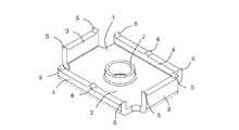
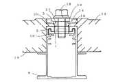
以下、本発明を実施するための最良の形態である太陽電池モジュールの取付構造について、図1乃至図9に基づいて詳細に説明する。図1(a)は、本発明の太陽電池モジュールの取付構造に用いるアース固定金具の平面図であり、(b)は(a)の正面図であり、(c)は(a)の側面図である。図2は、本発明の太陽電池モジュールの取付構造に用いるアース固定金具を示す斜視図である。また、図3は、本発明の太陽電池モジュールの取付構造に用いる横桟に図1に示すアース固定金具を挿通する斜視図である。更に、図4は、横桟に太陽電池モジュールを載置する斜視図である。図5は、横桟に載置された太陽電池モジュール上側から押えるカバー部材と、カバー部材を貫通するボルトの斜視図である。図6は、横桟に図1に示すアース固定金具を挿通し、カバー部材で太陽電池モジュールを載置した状態の断面図である。 Hereinafter, a solar cell module mounting structure that is the best mode for carrying out the present invention will be described in detail with reference to FIGS. 1 to 9. Fig.1 (a) is a top view of the earth fixing metal fitting used for the attachment structure of the solar cell module of this invention, (b) is a front view of (a), (c) is a side view of (a). It is. FIG. 2 is a perspective view showing a grounding fixture used in the solar cell module mounting structure of the present invention. FIG. 3 is a perspective view in which the grounding fixture shown in FIG. 1 is inserted into the horizontal rail used in the solar cell module mounting structure of the present invention. Furthermore, FIG. 4 is a perspective view of placing the solar cell module on the horizontal rail. FIG. 5 is a perspective view of a cover member pressed from the upper side of the solar cell module placed on the horizontal rail and a bolt penetrating the cover member. FIG. 6 is a cross-sectional view of a state in which the grounding fixture shown in FIG. 1 is inserted into the horizontal rail and the solar cell module is placed on the cover member.
まず、本例の太陽電池モジュールの取付構造に用いるアース固定金具を説明する。図1(a)、(b)、(c)、図2に示すように、アース固定金具1は、平面部2から上側に曲げられた立上り面3,4を具備した形状で形成されている。前記立上り部の先端部には突出部5,6を具備しており、平面部2にはボルト受部7を有している。 First, the earth fixture used in the solar cell module mounting structure of this example will be described. As shown in FIGS. 1A, 1 </ b> B, 1 </ b> C, and 2, the
このアース固定金具1の平面部2は長方形の形状をしており、立上り部3は平面部2の短辺に対して略垂直に形成されその立上り幅は本例では約15mmとされている。また、立上り部4は平面部2の長辺に対して略垂直に形成されその立上り幅は本例では約30mmとされている。そして、立上り部3,4の先端に備えられた突出部5,6は、上方に向かうに従って先が細くなる先の尖った三角形状に形成されている。また、ボルト受部7は、平面部2の中央から上方に延び出す円筒形状に形成されており、その内面にはボルトと螺合する雌ねじが形成されている。 The flat surface portion 2 of the
このアース固定金具1は、板金をプレス成形したものであり、例えば、平面部2に対して立上り部3,4を展開した状態で突出部5,6とボルト受部7を形成するための小孔と共に打抜いた上で、立上り部3,4を平面部2に対して略垂直に曲げ加工した上で、平面部2中央の小孔をバーリング加工によって拡径すると共にボルト受部7となる円筒部を形成し、その円筒部の内面に所定の雌ねじを刻設することでアース固定金具1が製造される。なお、上記の工程は一例であり、その他の工程や方法によってアース固定金具1を製造しても良い。なお、本例では、立上り部3,4を平面部2に対して略垂直に立上ったものを示しているが、斜めに傾斜して立上るように形成しても良い。 The
前記アース固定金具の前記突出部5は、二等辺三角形の長辺(二等辺)を斜面にし、前記斜面を内側向けた形状で高さは1.5mmが望ましく、1.5mm以下では、太陽電池モジュール19の設置時の上下方向の誤差によって横桟8との隙間が生じ、突出部が届かない場合があり、1.5mm以上では、太陽電池モジュール19が突出部によって持ち上げられ段差が生じ、美観が悪くなる恐れがある。また、二等辺三角形の長辺を斜面にした場合、突出部の先端が最も外側に配置され、太陽電池モジュール19が左右方向の誤差が生じても電気的の接続ができ、二等辺三角形の長辺を斜面にしなかった場合、突出部の先端が外側よりやや内側に配置される為、太陽電池モジュール19が左右方向の誤差が生じた場合、電気的の接続ができなくなる。なお、アース固定金具1の材質は、例えば鋼板で、板厚は2.3mm、シルバーである。 The projecting
続いて、本例の太陽電池モジュールの取付構造に用いる横桟8を説明する。横桟8は、図3に示すように縦長の長方形で、上部に載置部9を有し、長手方向に沿って前記アース固定金具1の立上り部4に関連した形状の一直線状に長手方向に延びる上辺溝部10を具備し太陽電池モジュール19のフレームの側面形状に関連した形状に形成してある。 Next, the
この横桟8の断面形状は、縦長の長方形で上側は開口されて、上部左右に横桟内側に向かって横桟の幅の1/4程度延びる載置部9があり、前記載置部9の先端から下側に延びる短線と、前記載置部9と平行に延びる略C字の形状を持つ上辺溝部10がある。なお、横桟8の材質は、アルミで、色はシルバーである。 The cross-sectional shape of the
続いて、本例の太陽電池モジュールの取付構造に用いる太陽電池モジュール19を説明する。太陽電池モジュール19は、図5に示すように横長の長方形で、枠体の外側面に設けられた係合溝部20を有している。 Then, the
係合溝部20の断面形状は、L字形状をしており、L字を90度回し、端部21を上側に配置したような形状を持つ。なお、太陽電池モジュール19の枠体の材質は、アルミで、色はブラックである。 The cross-sectional shape of the
続いて、本例の太陽電池モジュールの取付構造に用いる押え部材12を説明する。押え部材12は、図5に示すように横長の長方形で、平面部13はフラット状に成形されており、裏面、左面、右面には凹状の凹み部14,15を有し、太陽電池モジュール19の係合溝部20を押える、押え部16を有している。更に平面部13に上下方向に貫通孔17を有している。 Next, the pressing
この押え部材12の凹み部15は太陽電池モジュール19の係合溝部20の端部21の高さに関連した凹み寸法で、太陽電池モジュール19が屋根上に配設される際に屋根の長さ方向に配置誤差が発生した場合、凹み部15で太陽電池モジュール19の係合溝部20の端部21に干渉して配置誤差を抑制し、もし、太陽電池モジュール19の係合溝部20の端部21が押え部16の下に配置された場合、押え部材12が係合溝部20の端部21によって、変形し盛上がる事によって、施工中に目視によって、不具合の発見ができる。なお、押え部材12材質は、アルミで、色はブラックである。 The recessed
次に、本例における太陽電池モジュールの取付構造について、施工手順に沿って詳細に説明する。本実施形態の太陽電池モジュールの施工方法は、第一の手順で、図3に示すように横桟8の左右一方の端から、上辺溝部10に図1に示したアース固定金具1を挿通し、定位置までスライドさせる。 Next, the mounting structure of the solar cell module in this example will be described in detail along the construction procedure. The solar cell module construction method of the present embodiment is a first procedure in which the
第二の手順で、図4に示すように横桟8の載置部9に太陽電池モジュール19の係合溝部20を載置する。 In the second procedure, as shown in FIG. 4, the engaging
第三の手順で、図5に示すように押え部材12の貫通孔17に上側からボルト18を挿通し、前記アース固定金具1をスライドさせて貫通孔17と位置を調整し、ボルト受部7と螺合させて、前記太陽電池モジュール19と前記横桟8に固定する。 In the third procedure, as shown in FIG. 5, the
この際、図6に示すようにアース固定金具1が、前記ボルト18によって上側へ引揚げられ、押え部材12とが互いに接近し、その間に配置された太陽電池モジュールと横桟の上辺溝部の上辺とが押え部材とアース固定金具とで挟まれて、突出部5が太陽電池モジュール19の係合溝部20の裏側に突き刺さり、係合溝部20の表面保護皮膜を破りアース固定金具1と電気的に接続され、更に横桟8の上辺溝部10の上側11の表面保護皮膜を破りアース固定金具1と電気的に接続される。 At this time, as shown in FIG. 6, the
このように、本実施形態によると、アース固定金具1によって、従来のように複数の金具を用いなくても、単品で太陽電池モジュールの固定とアース接続が同時にできることが可能となり、コストを低減させることができる。特に、導通性に優れたものを用いることで、より高いアース接続できる。 As described above, according to the present embodiment, the earth fixing
以上、本発明について好適な実施形態を挙げて説明したが、本発明はこれらの実施形態に限定されるものではなく、以下に示すように、本発明の要旨を逸脱しない範囲において、種々の改良および設計の変更が可能である。 The present invention has been described with reference to preferred embodiments. However, the present invention is not limited to these embodiments, and various modifications can be made without departing from the spirit of the present invention as described below. And design changes are possible.
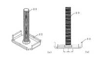
すなわち、本実施形態ではアース固定金具1のボルト受部7にボルト18が螺合するものを示したが、図7に示すようなアース固定金具1のボルト受部7にボルト23を下側より螺合させているアース固定金具22でも良い。これにより、押え部材12の貫通孔17との位置の調整が行い易くすることができる。 That is, in the present embodiment, the
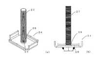
また、本実施形態ではアース固定金具1のボルト受部7にボルト18が螺合するものを示したが、図8に示すようなアース固定金具1の平面部25に貫通孔26を設け、ボルト27を下側より挿通し、点溶接28にて固定させているアース固定金具24でも良い。これにより、押え部材12の貫通孔17との位置の調整が行い易くすることができる。 Further, in the present embodiment, the
1 アース固定金具
2 平面部
3 立上り部
4 立上り部
5 突出部
6 突出部
7 ボルト受部
8 横桟
9 載置部
10 上辺溝部
11 上辺溝部の上側
12 押え部材
13 平面部
14 凹み部
15 凹み部
16 押え部
17 貫通孔
18 ボルト
19 太陽電池モジュール
20 係合溝部
21 端部
22 アース固定金具
23 ボルト
24 アース固定金具
25 平面部
26 貫通孔
27 ボルト
28 点溶接DESCRIPTION OF
Claims (3)
Translated fromJapanese該横桟の前記載置部に載置された前記太陽電池モジュール同士を同時に上側から押えられると共に上下方向に貫通する貫通孔を有する押え部材と、
該押え部材の前記貫通孔に挿通されるボルトと、
該ボルトを受けるボルト受部を有し、前記押え部材の下側に位置するように前記横桟の前記上辺溝部内に挿入され、前記ボルトにより前記押え部材と前記ボルト受部とを締結することで、前記太陽電池モジュール同士と前記横桟とを同時に固定すると共に電気的に接続するアース固定金具と
を具備し、
該アース固定金具は、
前記ボルト受部が形成された本体部から上側に延び、その先端が前記太陽電池モジュールの下側及び前記横桟における前記上辺溝部の内面上側と接触する立上り部を具備することを特徴とする太陽電池モジュールの取付構造。A mounting portion for mounting the solar cell module disposed on the roof at both ends, and a horizontal rail having an upper side groove portion extending in the longitudinal direction;
A holding member having a through-hole penetrating in the vertical direction while simultaneously pressing the solar cell modules placed on the placement portion of the horizontal rail from above;
A bolt inserted through the through hole of the pressing member;
A bolt receiving portion for receiving the bolt; and being inserted into the upper side groove portion of the horizontal rail so as to be positioned below the pressing member, and fastening the pressing member and the bolt receiving portion by the bolt. The solar cell module and the horizontal rail are fixed at the same time and comprise a grounding fixture for electrical connection,
The earth fixing bracket is
The sun includes a rising portion that extends upward from a main body portion on which the bolt receiving portion is formed, and that has a tip that contacts a lower side of the solar cell module and an upper surface of the upper side groove portion of the horizontal rail. Battery module mounting structure.
前記立上り部の先端に形成され、前記太陽電池モジュールの下側及び前記横桟における前記上辺溝部の内面上側に突き刺さる突出部を有していることを特徴とする請求項1に記載の太陽電池モジュールの取付構造。The earth fixing bracket is
2. The solar cell module according to claim 1, wherein the solar cell modulehas a protruding portion formed at a tip of the rising portion and piercing the lower side of the solar cell module and the upper surface of the upper side groove portion of the horizontal rail. Mounting structure.
ボルトを受けるボルト受部と、 A bolt receiving portion for receiving the bolt;
該ボルト受部が形成された本体部から上側に延び、先端が前記太陽電池モジュールの下側及び前記横桟における前記上辺溝部の内面上側と接触可能な立上り部と、 A rising portion that extends upward from a main body portion in which the bolt receiving portion is formed, and whose tip can contact the lower side of the solar cell module and the inner surface upper side of the upper side groove portion in the horizontal rail,
前記立上り部の先端に少なくとも形成され、前記太陽電池モジュールの下側及び前記横桟における前記上辺溝部の内面上側に突き刺さる突出部と A protrusion that is formed at least at the tip of the rising portion and pierces the lower side of the solar cell module and the upper surface of the upper side groove in the horizontal rail;
を具備することを特徴とするアース固定金具。An earth fixing metal fitting characterized by comprising:
Priority Applications (1)
| Application Number | Priority Date | Filing Date | Title |
|---|---|---|---|
| JP2006089662AJP4679409B2 (en) | 2006-03-29 | 2006-03-29 | Grounding structure and grounding fixture for solar cell module |
Applications Claiming Priority (1)
| Application Number | Priority Date | Filing Date | Title |
|---|---|---|---|
| JP2006089662AJP4679409B2 (en) | 2006-03-29 | 2006-03-29 | Grounding structure and grounding fixture for solar cell module |
Publications (2)
| Publication Number | Publication Date |
|---|---|
| JP2007262764A JP2007262764A (en) | 2007-10-11 |
| JP4679409B2true JP4679409B2 (en) | 2011-04-27 |
Family
ID=38636009
Family Applications (1)
| Application Number | Title | Priority Date | Filing Date |
|---|---|---|---|
| JP2006089662AActiveJP4679409B2 (en) | 2006-03-29 | 2006-03-29 | Grounding structure and grounding fixture for solar cell module |
Country Status (1)
| Country | Link |
|---|---|
| JP (1) | JP4679409B2 (en) |
Families Citing this family (23)
| Publication number | Priority date | Publication date | Assignee | Title |
|---|---|---|---|---|
| US7856769B2 (en) | 2004-02-13 | 2010-12-28 | Pvt Solar, Inc. | Rack assembly for mounting solar modules |
| US8344239B2 (en) | 2004-02-13 | 2013-01-01 | Pvt Solar, Inc. | Mechanism for mounting solar modules |
| US7900407B2 (en) | 2004-02-13 | 2011-03-08 | Pvt Solar, Inc. | Interconnected solar module design and system |
| WO2008028151A2 (en)* | 2006-08-31 | 2008-03-06 | Pvt Solar, Inc. | Technique for electrically bonding solar modules and mounting assemblies |
| US7721492B2 (en) | 2006-09-06 | 2010-05-25 | Pvt Solar, Inc. | Strut runner member and assembly using same for mounting arrays on rooftops and other structures |
| US7857269B2 (en) | 2006-11-29 | 2010-12-28 | Pvt Solar, Inc. | Mounting assembly for arrays and other surface-mounted equipment |
| CN101387151B (en)* | 2008-09-18 | 2011-05-11 | 吴文强 | Flat-plate fastening system |
| JP4511616B2 (en)* | 2008-11-05 | 2010-07-28 | シャープ株式会社 | Solar cell module mount and solar power generation system using the same |
| JP5666096B2 (en)* | 2009-02-25 | 2015-02-12 | 三洋電機株式会社 | Solar cell module |
| FR2949521A1 (en)* | 2009-08-26 | 2011-03-04 | Actif En Vertes | DEVICE FOR FIXING AT LEAST ONE PANEL ON A CARRIER STRUCTURE |
| JP2011084984A (en)* | 2009-10-19 | 2011-04-28 | Sharp Corp | Structure support tool, solar cell module system using the same and structure installing method using the same |
| EP2317244A1 (en)* | 2009-10-27 | 2011-05-04 | Reich + Nievergelt AG | On-roof assembly system for solar modules |
| JP5501125B2 (en) | 2010-07-06 | 2014-05-21 | 株式会社屋根技術研究所 | Fixed member |
| JP5687473B2 (en)* | 2010-11-10 | 2015-03-18 | ホリー株式会社 | Mounting device for installation on the roof |
| JP4856279B1 (en)* | 2011-05-30 | 2012-01-18 | マジカナテック株式会社 | Roof panel fittings |
| CN103088974B (en)* | 2011-10-27 | 2016-03-16 | 日轻金Act株式会社 | The fixed structure of frame material |
| CN102720307B (en)* | 2012-06-13 | 2014-04-30 | 美联钢结构建筑系统(上海)股份有限公司 | Butt seam connecting device for horizontal single-deck metal wall panels |
| JP2015002265A (en)* | 2013-06-14 | 2015-01-05 | 港製器工業株式会社 | Assembly metal fitting with grounding function of frame for photovoltaic power generation panel |
| JP6280712B2 (en)* | 2013-09-09 | 2018-02-14 | 元旦ビューティ工業株式会社 | Conductive member for grounding and solar cell module grounding structure using the same |
| JP6386303B2 (en)* | 2014-08-29 | 2018-09-05 | 株式会社Nttファシリティーズ | Solar cell panel mounting structure and solar cell panel mounting method |
| US20160344338A1 (en)* | 2015-08-07 | 2016-11-24 | Everest Solar Systems, LLC | Profiled-Rail Retaining Element Having Protuberances for a Mechanical and Electrical Connection |
| JP2022097083A (en)* | 2020-12-18 | 2022-06-30 | 武蔵 絵美理 | Photovoltaic power generation panel installation base |
| JP7633134B2 (en) | 2021-10-14 | 2025-02-19 | 日栄インテック株式会社 | Walkway Plate |
Family Cites Families (6)
| Publication number | Priority date | Publication date | Assignee | Title |
|---|---|---|---|---|
| JP3437891B2 (en)* | 1996-03-18 | 2003-08-18 | シャープ株式会社 | Mounting structure of solar cell module |
| JP3550950B2 (en)* | 1997-06-13 | 2004-08-04 | 三菱電機株式会社 | Panel structure fixing device |
| JP3502262B2 (en)* | 1998-05-13 | 2004-03-02 | シャープ株式会社 | Mounting structure of solar cell module |
| JP2000100490A (en)* | 1998-09-24 | 2000-04-07 | Matsushita Electric Works Ltd | Grounding structure for solar battery module |
| JP2004060358A (en)* | 2002-07-31 | 2004-02-26 | Kyocera Corp | Roof fixing device and solar energy utilization structure using the same |
| JP4190339B2 (en)* | 2003-04-23 | 2008-12-03 | 三洋電機株式会社 | Solar cell device fixed to the roof |
- 2006
- 2006-03-29JPJP2006089662Apatent/JP4679409B2/enactiveActive
Also Published As
| Publication number | Publication date |
|---|---|
| JP2007262764A (en) | 2007-10-11 |
Similar Documents
| Publication | Publication Date | Title |
|---|---|---|
| JP4679409B2 (en) | Grounding structure and grounding fixture for solar cell module | |
| JP5705380B2 (en) | Solar cell module fixing structure | |
| JP5501125B2 (en) | Fixed member | |
| JP4721081B1 (en) | Support and fixing structure of solar energy device | |
| JPWO2006016412A1 (en) | Solar cell unit mounting device | |
| US20140069877A1 (en) | Solar panel frame clamps | |
| US20150101654A1 (en) | Solar panel array | |
| CN207782738U (en) | Solar photovoltaic battery component fixed structure | |
| KR101355168B1 (en) | Installing structure for solar cell module | |
| US8672702B2 (en) | Electrical conductor arrangement as a component of a photovoltaic array | |
| JP2009091825A (en) | Solar cell module mounting jig and mounting structure | |
| JP6025770B2 (en) | Fixing bracket for solar cell module and fixing structure for solar cell module | |
| CN219718153U (en) | Photovoltaic panel's installing frame and photovoltaic panel | |
| JP2013221323A (en) | Mounting bracket for solar cell module | |
| JP2012241410A (en) | Metal fitting for installing solar module on slate roof | |
| CN215990684U (en) | Photovoltaic module lightning protection installing the system and photovoltaic roofing | |
| JP5505084B2 (en) | Grounding method for photovoltaic modules | |
| CN210201786U (en) | Photovoltaic support ground connection conducting strip | |
| CN217353263U (en) | Photovoltaic module connection structure and photovoltaic roof | |
| CN207782737U (en) | Solar photovoltaic assembly fixed structure | |
| JP2016098595A (en) | Power generation panel fixture | |
| CN219204431U (en) | Briquetting accessory and photovoltaic system are used in photovoltaic module installation | |
| CN207124598U (en) | A kind of photovoltaic module briquetting and the photovoltaic generating system using the briquetting | |
| CN117792250B (en) | Photovoltaic panel mounting system | |
| JP3179995U (en) | Solar panel mounting anchor |
Legal Events
| Date | Code | Title | Description |
|---|---|---|---|
| A621 | Written request for application examination | Free format text:JAPANESE INTERMEDIATE CODE: A621 Effective date:20080924 | |
| A977 | Report on retrieval | Free format text:JAPANESE INTERMEDIATE CODE: A971007 Effective date:20100917 | |
| A131 | Notification of reasons for refusal | Free format text:JAPANESE INTERMEDIATE CODE: A131 Effective date:20101019 | |
| A521 | Request for written amendment filed | Free format text:JAPANESE INTERMEDIATE CODE: A523 Effective date:20101209 | |
| TRDD | Decision of grant or rejection written | ||
| A01 | Written decision to grant a patent or to grant a registration (utility model) | Free format text:JAPANESE INTERMEDIATE CODE: A01 Effective date:20110118 | |
| A01 | Written decision to grant a patent or to grant a registration (utility model) | Free format text:JAPANESE INTERMEDIATE CODE: A01 | |
| A61 | First payment of annual fees (during grant procedure) | Free format text:JAPANESE INTERMEDIATE CODE: A61 Effective date:20110201 | |
| R150 | Certificate of patent or registration of utility model | Ref document number:4679409 Country of ref document:JP Free format text:JAPANESE INTERMEDIATE CODE: R150 Free format text:JAPANESE INTERMEDIATE CODE: R150 | |
| FPAY | Renewal fee payment (event date is renewal date of database) | Free format text:PAYMENT UNTIL: 20140210 Year of fee payment:3 | |
| R250 | Receipt of annual fees | Free format text:JAPANESE INTERMEDIATE CODE: R250 | |
| S531 | Written request for registration of change of domicile | Free format text:JAPANESE INTERMEDIATE CODE: R313531 | |
| R350 | Written notification of registration of transfer | Free format text:JAPANESE INTERMEDIATE CODE: R350 | |
| R250 | Receipt of annual fees | Free format text:JAPANESE INTERMEDIATE CODE: R250 | |
| R250 | Receipt of annual fees | Free format text:JAPANESE INTERMEDIATE CODE: R250 | |
| R250 | Receipt of annual fees | Free format text:JAPANESE INTERMEDIATE CODE: R250 |