JP4679190B2 - X-ray diagnostic imaging equipment - Google Patents
X-ray diagnostic imaging equipmentDownload PDFInfo
- Publication number
- JP4679190B2 JP4679190B2JP2005078362AJP2005078362AJP4679190B2JP 4679190 B2JP4679190 B2JP 4679190B2JP 2005078362 AJP2005078362 AJP 2005078362AJP 2005078362 AJP2005078362 AJP 2005078362AJP 4679190 B2JP4679190 B2JP 4679190B2
- Authority
- JP
- Japan
- Prior art keywords
- ray
- image
- region
- image data
- body motion
- Prior art date
- Legal status (The legal status is an assumption and is not a legal conclusion. Google has not performed a legal analysis and makes no representation as to the accuracy of the status listed.)
- Expired - Fee Related
Links
Images


Landscapes
- Image Processing (AREA)
- Image Analysis (AREA)
- Apparatus For Radiation Diagnosis (AREA)
Description
Translated fromJapanese本発明は、X線画像診断装置に係り、特にカテーテルやガイドワイヤ等の低コントラスト物の視認性の向上に好適なX線画像診断装置に関する。 The present invention relates to an X-ray diagnostic imaging apparatus, and more particularly to an X-ray diagnostic imaging apparatus suitable for improving the visibility of low-contrast objects such as catheters and guide wires.
X線透視撮影台や循環器X線検査装置等の医用X線透視撮影装置は、診断の分野においては欠かせないものとなっているが、最近は診断のみならず治療にも使われるようになってきた。この治療は、X線透視下において先端にさまざまな器具を取り付けたカテーテルを被検者の血管や臓器に挿入して行なうものであって、従来、開腹手術をせざるを得なかった治療に対して、被検者に与える苦痛を少なくでき、かつ安価に治療ができるという大きなメリットを持つため、急速に普及している。このような治療方法は、IVR(Interventional Radiology)施術と呼ばれている。
このIVR施術は、上記のようにX線透視画像を見ながらカテーテルを目的部に挿入し、例えば、微小のカッターやレーザーで病変部を切除したり、薬剤を投与して病変部の治療を行うものである。Medical X-ray fluoroscopy devices such as X-ray fluoroscopy tables and cardiovascular X-ray examination devices are indispensable in the field of diagnosis, but recently they are used not only for diagnosis but also for treatment. It has become. This treatment is performed by inserting a catheter with various instruments attached to the tip under fluoroscopy into the blood vessels and organs of the subject. Since it has a great merit that it can reduce the pain given to the subject and can be treated at low cost, it is rapidly spreading. Such a treatment method is called IVR (Interventional Radiology) treatment.
In this IVR treatment, the catheter is inserted into the target part while viewing the X-ray fluoroscopic image as described above. For example, the lesion part is excised with a micro cutter or laser, or the drug is administered to treat the lesion part. Is.
このようなIVR施術において、カテーテル先端の認識性が重要となり、該カテーテルを操作する術者は、常にカテーテルの先端が被検者の体内のどこに存在するかを把握する必要がある。
特に、脳血管に対する施術が必要な場合にはマイクロカテーテルと呼ばれる直径1mm以下の極細のカテーテルが使用されるため、カテーテルの先端位置を把握することは困難であった。
また、脳血管や心臓血管に対する処置を行う場合、大腿動静脈、肘部動静脈、橈骨動脈(手首)等からカテーテルを挿入し、胸部を経由するため、X線を透過させない背骨や、X線を透過しやすい肺野部があり、明暗の差が激しく、低コントラストのカテーテルを認識することは非常に困難である。
このようなIVR施術におけるカテーテル先端の認識率を高める技術として、特許文献1,2に開示されているものがある。In such IVR treatment, the recognition of the catheter tip is important, and the operator who operates the catheter always needs to know where the tip of the catheter is in the body of the subject.
In particular, when a treatment for a cerebral blood vessel is required, an extremely fine catheter called a microcatheter having a diameter of 1 mm or less is used, and it is difficult to grasp the position of the distal end of the catheter.
In addition, when performing treatments for cerebral blood vessels and cardiovascular vessels, a catheter is inserted from the femoral arteriovenous, elbow arteriovenous, radial artery (wrist), etc. It is difficult to recognize a low-contrast catheter because there is a lung field part that is easy to penetrate, and there is a great difference between light and dark.
Patent Documents 1 and 2 disclose techniques for increasing the recognition rate of the catheter tip in such an IVR treatment.
特許文献1は、X線透視撮影装置により、施術対象器官に造影剤を注入した造影画像を撮影し、この造影画像のうちの造影部分領域の辺縁部を辺縁画像として計算する辺縁部計算手段を有して、透視画像と前記辺縁画像とを合成して表示するものである。 Patent Document 1 uses an X-ray fluoroscopic apparatus to capture a contrast image in which a contrast medium is injected into an operation target organ, and calculate a marginal portion of the contrasted partial region of the contrasted image as a marginal image. It has a calculation means and combines and displays a fluoroscopic image and the edge image.
特許文献2は、ガイドワイヤーに所定の機械的な微振動を与え、この微振動量に基づいてガイドワイヤーを臓器から弁別し、前記ガイドワイヤーの振動周波数を臓器の生理的な動きによる振動と異なったものとすることで、ガイドワイヤーの位置検出を行う。
上記のように、カテーテル先端の位置を把握する手段として、上記特許文献1に記載されている造影剤を用いる方法や、特許文献2に記載されているカテーテル先端を振動させて周囲と区別する手段がある。 As described above, as means for grasping the position of the catheter tip, the method using the contrast agent described in Patent Document 1 above, or the means for vibrating the catheter tip described in Patent Document 2 to distinguish it from the surroundings There is.
しかし、特許文献1は、造影剤を用いることが必須であるために、該造影剤は被検者に副作用を起こす場合や、被検者によってはアレルギー反応が起こる場合があるので、被検者に与える苦痛は少なくない。
また、特記文献2のカテーテル先端を振動させる方法では、カテーテルの振動装置が必要となり、経済性の面で難点がある。However, in Patent Document 1, since it is essential to use a contrast medium, the contrast medium may cause a side effect on the subject or an allergic reaction may occur depending on the subject. There is not a lot of pain to give to.
In addition, the method of vibrating the catheter tip of Special Reference 2 requires a catheter vibration device, which is difficult in terms of economy.
そこで本発明の目的は、造影剤や振動装置等の外部装置を使用することなく、カテーテル先端を周囲と区別してこれを強調表示し、前記カテーテル及びガイドワイヤの視認を容易にすることができるX線画像診断装置を提供することにある。 Therefore, an object of the present invention is to distinguish the tip of the catheter from the surrounding and highlight it without using an external device such as a contrast medium or a vibration device, so that the catheter and the guide wire can be easily viewed. An object of the present invention is to provide a line image diagnostic apparatus.
一般に、カテーテルやガイドワイヤなど体外から挿入されるオブジェクトは、心臓や呼吸等に伴う体動方向とは異なる動きをするため、各画素の動き方向を算出することにより分別が可能となる。
本発明は上記考えに基づいて成されたもので、カテーテル先端などの小頻出度方向に動くオブジェクトを検出し、これを強調表示することにより前記カテーテル等の視認性の向上を図るもので、上記目的は以下の手段によって達成される。In general, an object inserted from outside the body, such as a catheter or a guide wire, moves differently from the body movement direction associated with the heart, breathing, or the like, and therefore can be distinguished by calculating the movement direction of each pixel.
The present invention has been made based on the above-described idea, and detects an object moving in a small frequency direction such as a catheter tip and highlights the object to improve visibility of the catheter or the like. The object is achieved by the following means.
(1)被検者にX線を照射するX線照射手段と、前記被検者を挟んで前記X線照射手段と対向して配置され前記被検者を透過したX線を検出するX線検出手段と、
該X線検出手段で検出したX線画像データを収集し、この収集した画像データに各種の画像処理を施して所望の画像を生成する画像処理手段と、 該画像処理手段で生成したX線画像を表示する表示手段とを備えたX線画像診断装置であって、前記画像処理手段は、前記収集した画像データから前記被検者の体動を検出する体動検出手段と、前記体動検出手段で検出した体動情報から非体動領域を検出する非体動検出手段と、前記非体動検出手段で検出した領域を現在のX線透視画像中に強調表示処理する非体動強調処理手段と、前記非体動強調処理手段で処理した画像を前記表示手段に表示制御する手段とを備えた構成である。
(1) X-ray irradiating means for irradiating the subject with X-rays, and X-ray for detecting X-rays that are disposed opposite to the X-ray irradiating means with the subject interposed therebetween and transmitted through the subject. Detection means;
Image processing means for collecting X-ray image data detected by the X-ray detection means and performing various image processing on the collected image data to generate a desired image; and an X-ray image generated by the image processing means an X-ray image diagnostic apparatus and a display means for displaying said image processing means includes a body motion detecting means for detecting a body motion of the subject from the image data the collected,the body motion detection and non-body motion detecting means for detectingthe non-body motion region from the detectedbody motion information unit,the non-body motion of the detected region in the current X-ray fluoroscopic image by the detection means for highlighting processing non body movement enhancement means and a configuration in which a means for displaying control the image processed bythe Hikaradado enhancement processing means on the display means.
(2)前記体動検出手段は、X線透視画像のフレーム間の移動方向を算出する移動方向算出手段により成され、前記非体動検出手段は、前記移動方向算出手段で算出した移動方向を記憶する移動方向メモリと、この移動方向メモリに記憶された1フレーム分の全てのデータに対して動いている画素の移動方向を算出して統計処理を行ない、この統計処理にて得た移動頻度の低い非体動オブジェクトを求める手段とから成る。(2) The body movement detection means is constituted by a movement direction calculation means for calculating a movement direction between frames of the X-ray fluoroscopic image, and the non-body movement detection means uses the movement direction calculated by the movement direction calculation means. The moving direction memory to be stored and the moving direction of the moving pixels for all the data for one frame stored in this moving direction memory are calculated and statistical processing is performed, and the moving frequency obtained by this statistical processing And a means for obtaining a low non-motion object.
(3)前記移動方向算出手段は、前記X線検出手段からのX線透視画像データを所要のライン分記憶するラインメモリと、このラインメモリのデータから濃度差の変化領域を抽出するエッジ抽出手段と、この抽出したエッジ画像を記憶するフレームメモリと、このフレームメモリのデータから所定形状と等しい領域を求めるパターンマッチング手段と、このパターンマッチング手段によるパターンマッチングの結果から移動物の移動方向を算出する。(3) The moving direction calculation means includes a line memory for storing X-ray fluoroscopic image data from the X-ray detection means for a required line, and an edge extraction means for extracting a density difference change region from the data in the line memory. A frame memory for storing the extracted edge image, a pattern matching means for obtaining an area equal to a predetermined shape from the data of the frame memory, and a moving direction of the moving object is calculated from a result of pattern matching by the pattern matching means. .
(4)前記非体動強調処理手段は、遅延手段により現在のX線透視画像を遅延をさせ、この遅延されたX線透視画像と前記非体動検出手段の出力とを入力してこれらを合成し、前記非体動検出手段で求めた頻度の低い移動を持つ領域を強調表示処理し、この強調表示処理された領域を前記X線透視画像に強調表示制御して、これを前記表示手段に表示する。(4) The non-body motion emphasis processing means delays the current X-ray fluoroscopic image by the delay means, inputs the delayed X-ray fluoroscopic image and the output of the non-body motion detection means, and outputs them. Combining and highlighting a region having a low frequency of movement determined by the non-body motion detecting means, and controlling the highlighting of the highlighted region on the X-ray fluoroscopic image. To display.
(5)前記非体動強調処理手段にカラー化処理する手段を備えて、前記強調表示領域をカラー表示したり、あるいは前記非体動強調処理手段に実線や破線によるコントラスト強調表示処理手段を備えて、前記強調表示領域をコントラスト強調表示して、カテーテル先端などの小頻出度方向に動くオブジェクトを強調表示する。(5) The non-body motion emphasis processing unit includes a color processing unit, and the emphasis display area is displayed in color, or the non-body motion emphasis processing unit includes a solid-line or broken-line contrast emphasis display processing unit. Then, the highlight area is displayed with contrast emphasis, and an object moving in the direction of small frequency such as a catheter tip is highlighted.
このように構成することにより、造影剤を使用すること無しに、あるいはガイドワイヤを振動させること無しに、体動と外部から挿入され人為的に操作されるカテーテルやガイドワイヤを分別することができ、更に分別したオブジェクトに対してカラー化処理等の強調表示を行うことにより、カテーテルやガイドワイヤの先端部の視認性の向上を図ることができる。 By configuring in this way, it is possible to separate the body movement and the catheter and the guide wire that are artificially operated from the outside without using a contrast agent or without vibrating the guide wire. Further, the visibility of the distal end portion of the catheter or guide wire can be improved by performing highlighting such as colorization processing on the further sorted object.
本発明によれば、造影剤や振動装置等の外部装置を使用することなく、カテーテル先端を周囲と区別してこれを強調表示し、前記カテーテル及びガイドワイヤの視認が容易となり、これによってIVR施術の効率化に寄与するものとなる。 According to the present invention, without using an external device such as a contrast medium or a vibration device, the distal end of the catheter is distinguished from the surrounding and highlighted so that the catheter and the guide wire can be easily viewed. It will contribute to efficiency.
本発明に係るX線画像診断装置の好ましい実施の形態について、以下の添付図面に従って詳細に説明する。
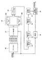
図1は、本発明によるX線画像診断装置の全体構成を示すブロック図である。Preferred embodiments of an X-ray image diagnostic apparatus according to the present invention will be described in detail with reference to the accompanying drawings.
FIG. 1 is a block diagram showing the overall configuration of an X-ray image diagnostic apparatus according to the present invention.
この図1のX線画像診断装置は、被検者1を透視撮影位置に載置する検診台2と、前記被検者1にX線を照射するX線照射装置3と、前記被検者1を挟んで前記X線照射装置3と対峙する位置に配置された前記被検者1を透過したX線を検出するX線平面検出器4と、システム全体を制御する制御パラメータを設定し操作するための操作器及び表示器を備えた制御操作卓5と、この制御操作卓5で設定した前記制御パラメータに基づいてシステム全体を制御するシステム制御装置6と、このシステム制御装置6から出力される撮影条件に対応した高電圧を発生し、これを前記X線照射装置3のX線管 3aに印加するX線高電圧装置7と、このX線高電圧装置7を制御するX線制御装置8と、前記X線平面検出器4で検出したX線検出信号を読み出し制御するX線平面検出器制御装置9と、このX線平面検出器制御装置9により読み出されたX線画像データを収集し、この収集した画像データに各種の画像処理を施して所望の画像データを生成し、この生成した画像データを表示制御する画像処理装置10と、前記表示制御されたX線画像を表示する表示装置11と、前記X線管3aから曝射されたX線の照射野を制限するX線可動絞り装置3bと、前記X線の強度分布を制御するためのX線補償フィルタ3cと、前記X線可動絞り装置3b及びX線補償フィルタ3cを制御する制御装置12と、前記被検者1を挟んで前記X線照射装置3と前記X線平面検出器6を対向する位置に支持するC字型支持器13と、この支持器13及び前記検診台2により被検者1を透視、撮影部位に位置決めするための機械機構部制御装置14とで構成される。
なお、前記X線照射装置3は、前記X線管3aと、X線可動絞り装置3bと、X線補償フィルタ3cとで構成されている。
また、上記図1の実施形態では、前記支持器13にC字型アームを用いた例をあげたが、X線透視撮影台等のX線透視ができるものであればどのような構成の支持器でも良い。The X-ray diagnostic imaging apparatus of FIG. 1 includes a screening table 2 for placing the subject 1 at a fluoroscopic position, an X-ray irradiation device 3 for irradiating the subject 1 with X-rays, and the subject The X-ray flat panel detector 4 that detects X-rays transmitted through the subject 1 disposed at a position facing the X-ray irradiation device 3 across 1 and the control parameters for controlling the entire system are set and operated. A
The X-ray irradiation device 3 includes the X-ray tube 3a, an X-ray movable diaphragm device 3b, and an X-ray compensation filter 3c.
In the embodiment shown in FIG. 1, an example in which a C-shaped arm is used as the support 13 has been described. However, any configuration that supports X-ray fluoroscopy such as an X-ray fluoroscopic imaging table is supported. A vessel may be used.
前記X線平面検出器4は、X線画像を直接デジタル画像として透視、撮影するために、デジタル画像がリアルタイムで得られる半導体式デジタルX線検出器で、被検者1を透過したX線を光に変換するシンチレータと、このシンチレータから出力される光を電荷に変換するフォトダイオード(例えば、アモルファスシリコン型)とから構成され、フォトダイオードの電荷をスイッチング素子(例えば、TFT(Thin Film Transistor))を経由して読み出すことによってX線画像データを得るものであり、一般には平面検出器(Flat Panel Detector)と呼ばれている。 The X-ray flat panel detector 4 is a semiconductor digital X-ray detector in which a digital image is obtained in real time in order to see and photograph an X-ray image directly as a digital image. It is composed of a scintillator that converts light and a photodiode (for example, amorphous silicon type) that converts light output from the scintillator to a charge, and the charge of the photodiode is a switching element (for example, TFT (Thin Film Transistor)) X-ray image data is obtained by reading out via, and is generally called a flat panel detector.
このX線平面検出器4は、被検者を透過したX線量に応じた電気信号に変換する検出部が多数平面マトリックス状に並んでおり、前記X線量は前記検出部それぞれで電気信号に変換された電気的画像信号になる。
この電気的画像信号は、前記X線平面検出器制御装置9で読出し制御され、さらにアナログ/デジタル変換器でデジタル画像信号に変換されて画像処理装置10に入力され、各種画像処理を行なってX線画像として表示装置11に表示し、診断に供される。This X-ray flat detector 4 has a large number of detectors arranged in a planar matrix for converting into an electric signal corresponding to the X-ray dose transmitted through the subject, and the X-ray dose is converted into an electric signal by each of the detectors. The electric image signal is obtained.
The electrical image signal is read out and controlled by the X-ray flat panel detector control device 9, and further converted into a digital image signal by an analog / digital converter and input to the
このような構成のX線平面検出器4は、上記のリアルタイムでX線画像が得られる特徴の他に、従来のスクリーン・フィルム検出系、輝尽性蛍光体検出器やイメージインテンスファイアを用いた検出器よりも薄型、軽量であり、システムの小型化にも有利なことからX線画像診断装置に幅広く採用されるようになった。 The X-ray flat panel detector 4 having such a configuration uses a conventional screen / film detection system, a photostimulable phosphor detector, and an image intensifier in addition to the above-mentioned feature that an X-ray image can be obtained in real time. Since it is thinner and lighter than the detector and is advantageous for miniaturization of the system, it has been widely adopted for X-ray diagnostic imaging equipment.
なお、本発明においては、X線透視画像(動画像)を出力するものであれば、どのようなX線検出器でも良く、該X線検出器の種別に限定するものではない。 In the present invention, any X-ray detector may be used as long as it outputs an X-ray fluoroscopic image (moving image), and is not limited to the type of the X-ray detector.
図2に、本発明の要部である画像処理装置10の構成ブロック図を示す。
本発明による体動検出と非体動強調表示は、この画像処理装置10を用いてX線平面検出器4で検出したX線透視画像データを処理して行なうものである。FIG. 2 is a block diagram showing the configuration of the
Body motion detection and non-body motion emphasis display according to the present invention are performed by processing the X-ray fluoroscopic image data detected by the X-ray flat panel detector 4 using the
本発明に適用される画像処理装置10は、X線平面検出器4で検出したX線透視画像データが入力される、後述のエッジ検出に必要な水平方向の数ライン分保存可能なラインメモリ20(後述のエッジ検出のカーネルにもよるが、2〜14ライン程度必要で、本実施例では6ライン分保存可能。本実施例のX線平面検出器では、行と列から成るマトリックス状に配列された画素の6行のデータ)と、このラインメモリ20から画像データを読み出して、濃度差が急激に変化している領域、例えば骨の輪郭やカテーテルの輪郭を抽出するためのエッジ抽出処理を行うエッジ抽出部21と、該抽出したエッジ画像を2フレーム分格納するフレームメモリ22a及び22bとを備えた二つのメモリ(2フレーム分とは2画面分のことで、例えば1000行×1000列の画素のあるX線検出器の場合は、1000行×1000列画素分のエッジ抽出データを保存する必要がある)と、前記フレームメモリ22aと22bの出力を入力してある形状のものと等しい領域があるかを探す出す処理、すなわち、連続するフレーム間のうち、前フレームの一部が後フレームのどこに含まれるかを算出する処理を行うパターンマッチング部23と、このパターンマッチング部23のパターンマッチングの結果からカテーテル、骨や血管などの全ての移動物の移動方向を算出する移動方向算出部24(移動物体の移動距離を知るためにパターンマッチングを用いており、画像内のある領域が、一定時間後の画像のどこにあるかを算出することで、移動距離を算出する)と、該算出した移動方向を格納する移動方向メモリ25と、この移動方向メモリ25に格納された1フレーム分の全てのデータに対してどの方向に動いている画素が多いか、逆に、希少な方向へ動いている画素を求めて統計処理を行なう移動方向統計部26と、この移動方向統計部26で求めた頻度の低い移動方向を持つ領域にフラグをセットする非体動検出部27と、現在のX線透視画像に上記処理分の遅延をかける遅延部28と、前記非体動検出部27の出力と前記遅延されたX線透視画像とを入力して前記フラグがセットされた領域の画素に対して強調表示処理を行う非体動強調処理部29とから構成される。 An
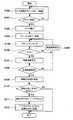
次に、上記構成の画像処理装置10の動作について図3に示すフローチャートを用いて説明する。 Next, the operation of the
(1)最初に、X線平面検出器4から出力されるX線透視画像をラインメモリ20に格納する(S100)。
これは、通常、エッジ検出には、ある大きさのカーネル(参照領域)が必要で、例えば、図4に示す斜線で示した注目点に対して左右上下の3画素の情報を使用するために7行×7列のカーネルが必要である。(1) First, the X-ray fluoroscopic image output from the X-ray flat panel detector 4 is stored in the line memory 20 (S100).
This is because edge detection usually requires a kernel (reference area) of a certain size, for example, to use the information of the three pixels on the left, right, top and bottom with respect to the point of interest shown by the diagonal lines in FIG. A 7 row x 7 column kernel is required.
(2)7行×7列のカーネルを使用する場合は、ラインメモリ20には最低でも6ライン分を格納する必要がある(S101)。
これは、図4に示したように、1ラインは現入力ラインで、残りの6ラインはメモリに保存しておくためである。(2) When using a 7-row × 7-column kernel, it is necessary to store at least 6 lines in the line memory 20 (S101).
This is because, as shown in FIG. 4, one line is the current input line and the remaining six lines are stored in the memory.
(3)必要なライン数(本実施例では6ライン)が格納されたことを確認後、次に入力されたライン画像と同期してエッジ抽出部21へ前記メモリ内容(1ライン前から6ライン前までの透視画像)を転送する。(3) After confirming that the required number of lines (six lines in this embodiment) is stored, the memory contents (six lines from the previous line) are sent to the
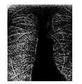
(4)エッジ抽出部21では、一般的にエッジ抽出に用いられるPrewittフィルタやSobelフィルタ(コロナ社:デジタル画像処理入門、酒井幸市著、1997年12月10日初版発行、30頁〜35頁に記載)を用いてエッジ抽出を行う(S102)。
このエッジ抽出部21でエッジ抽出した結果の一例を図5に示す。(4) In the
An example of the result of edge extraction by the
(5)エッジ抽出した画像はフレームメモリ22a,22bに格納される(S103)。
これらのフレームメモリには前フレームのエッジ検出画像も格納されている。
すなわち、前記フレームメモリ22a,22bのうちの1つには、前フレームのエッジ抽出画像が、他の1つには今回のエッジ抽出画像が格納される。(5) The edge extracted image is stored in the
These frame memories also store the edge detection image of the previous frame.
That is, the edge extracted image of the previous frame is stored in one of the
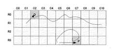
(6)次に、今回と前回のエッジ画像が格納されているフレームメモリ22a,22bの一部の領域(例えば、20行×20列の領域)を対象として、今回のエッジ画像に前回のエッジ画像とマッチする領域があるかどうかを周知のパターンマッチング手法(昭光堂:C言語による画像処理入門、安居院猛、長尾智晴共著、2000年11月20日初版発行、159頁に記載)を用いて確認する(S104)。(6) Next, for the part of the
(7)今、前フレームの内容が図6のようになっており、現フレームの内容が図7のようになっている場合、図6における(C1,R1)の領域Oと一致するパターンを図7の(C0,R0)から順に確認していくと、(C2,R0)で適合が確認される(S105)。(7) Now, if the contents of the previous frame are as shown in FIG. 6 and the contents of the current frame are as shown in FIG. 7, the pattern that matches the area O of (C1, R1) in FIG. When checking sequentially from (C0, R0) in FIG. 7, conformity is confirmed at (C2, R0) (S105).
(8)この場合には、領域Oに含まれるオブジェクトは(C1,R1)から(C2,R0)に移動したことになる。
移動方向は、移動方向算出部24により、逆正接tan-1(y/x)を使用することで算出が可能である(S107)。
このように、(C1,R1)から(C2,R0)に移動した場合には、移動距離は(1,1)となるため、tan-1(1/1)=45度となる。(8) In this case, the object included in the region O has moved from (C1, R1) to (C2, R0).
The moving direction can be calculated by using the arctangent tan−1 (y / x) by the moving direction calculation unit 24 (S107).
Thus, when moving from (C1, R1) to (C2, R0), the moving distance is (1, 1), and tan−1 (1/1) = 45 degrees.
(9)同様な確認をフレーム内全ての領域に対して行い、各領域の移動方向を移動方向メモリ25に格納していく(S108)。(9) The same confirmation is performed for all areas in the frame, and the movement direction of each area is stored in the movement direction memory 25 (S108).
(10)フレーム内の全ての領域に対してパターンマッチングを行った後に、移動方向メモリ25に格納されている各領域の移動方向を移動方向統計部26にて統計処理する(S109)。(10) After pattern matching is performed on all the areas in the frame, the movement
(11)また、心臓や呼吸等による体動は視野全ての移動方向が同一ではないため、フレーム内全ての領域に対してパターンマッチングを行うと移動方向が多数出現し、非体動オブジェクトの検出ができない可能性がある。
このため、パターンマッチングを行う範囲を制限することも有効である(S106)。例えば、全視野が1000×1000画素(横1000画素、縦1000画素)の場合、この内の300×300画素の範囲内を検索する。
この検索範囲は部位に応じて変更することも有効である。(11) Since the movement direction of the visual field is not the same in the movement direction of the field of view due to the heart or respiration, many movement directions appear when pattern matching is performed on all areas in the frame, and detection of non-body movement objects is performed. May not be possible.
For this reason, it is also effective to limit the range for pattern matching (S106). For example, when the entire field of view is 1000 × 1000 pixels (horizontal 1000 pixels, vertical 1000 pixels), the range of 300 × 300 pixels is searched.
It is also effective to change this search range according to the part.
(12)前記移動方向統計部26の統計処理手段としては、一般的なヒストグラムを使用し、各移動方向に適合する領域がいくつあるのかを計算する。
ヒストグラムの小さい領域が存在する場合には、その領域は特異な領域となり、人体の動きとは異なるもの、すなわち体外から挿入されて、人為的に操作されているカテーテルやガイドワイヤが存在することになる(S110)。(12) As a statistical processing means of the moving
If there is a small area in the histogram, the area will be a unique area, which is different from the movement of the human body, that is, there are catheters and guide wires that are inserted from outside the body and are manipulated artificially. (S110).
(13)前記頻度の低い方向を持つヒストグラムの小さい領域内の現在のX線透視画像の画素に対してフラグ“1”をセットする(S111)。
なお、非体動オブジェクトを検出するためにヒストグラムを使用せず、分散がある閾値以上の領域を非体動としてもなんら問題はない。(13) A flag “1” is set for the pixel of the current fluoroscopic image in the small region of the histogram having the low frequency direction (S111).
It should be noted that there is no problem even if a histogram is not used to detect a non-body motion object and a region where the variance is greater than or equal to a certain threshold value is non-body motion.
(14)最後に、非体動強調処理部29には、前記非体動検出部27で検出したカテーテル等の非体動オブジェクトであることを示す“1”フラグを有する画素と、遅延部28で現在のX線透視画像より前記処理時間に相当する時間だけ遅延されたX線透視画像とを入力して、前記“1”フラグの付いている画素に対して、該画素が強調表示されるようにその画素値を変化させ、前記遅延されたX線透視画像との同期をとって前記変化された画素値を有する画素と前記X線透視画像とを非体動強調処理部で合成して、この合成されたX線透視画像を表示装置11に表示する。(14) Finally, the non-body motion
前記表示装置11がカラー表示可能な場合には、前記強調表示する画素についてカラー化処理を行い、これと前記X線透視画像とを合成して前記強調表示画素をカラー表示する(S112)。
前記カラー化処理は、“1”フラグを持つ画素に対して、例えば最も目立つ色である赤色で表示したり、表示装置11がモノクロ表示のみである場合には、“1”フラグを持つ画素にたいして実線や破線を付加することや、“1”フラグの画素領域のみコントラストを向上させる方法、あるいは“1”フラグの領域に対するリカーシブフィルタ処理を行わないで動きボケを起こさなくする方法等により強調表示する。If the display device 11 is capable of color display, the pixel to be highlighted is subjected to colorization processing, and this is combined with the X-ray fluoroscopic image to display the highlighted pixel in color (S112).
The colorization processing is performed on a pixel having a “1” flag, for example, when the pixel that has the “1” flag is displayed in red, which is the most prominent color, or when the display device 11 is only monochrome display. Emphasize display by adding a solid line or a broken line, improving the contrast only for the pixel area of the “1” flag, or eliminating the recursive filter processing for the “1” flag area. .
以上の画像処理により、造影剤を使用すること無しに、あるいはガイドワイヤを振動させること無しに、体動と外部から挿入され人為的に操作されるカテーテルやガイドワイヤを分別することができ、更に分別したオブジェクトに対してカラー化処理等の強調表示を行うことで、カテーテルやガイドワイヤの先端部の視認性は向上する。 Through the above image processing, it is possible to separate the body movement from the externally inserted catheter and guide wire without using a contrast agent or without vibrating the guide wire, and further, Visibility of the distal end portion of the catheter or guide wire is improved by performing highlighting such as colorization processing on the sorted object.
1 被検者、2 被検者1を載置する検診台、3 X線照射装置、3a X線管、4 X線平面検出器、5 制御操作卓、6 システム制御装置、7 X線高電圧装置、8 X線制御装置、9 平面検出器制御装置、10 画像処理装置、11 表示装置、13 支持器、14 機械機構部制御装置、20 ラインメモリ、21 エッジ抽出部、22 フレームメモリ、23 パターンマッチング部、24 移動方向算出部、25 移動方向メモリ部、26 移 動方向統計部、27 非体動検出部、28 遅延部、29 非体動強調処理部 1 Examinee, 2 Examination table on which Subject 1 is placed, 3 X-ray irradiation device, 3a X-ray tube, 4 X-ray flat panel detector, 5 Control console, 6 System controller, 7 X-ray high voltage Device, 8 X-ray control device, 9 Planar detector control device, 10 Image processing device, 11 Display device, 13 Support device, 14 Mechanical mechanism control device, 20 Line memory, 21 Edge extraction unit, 22 Frame memory, 23 pattern Matching unit, 24 movement direction calculation unit, 25 movement direction memory unit, 26 movement direction statistics unit, 27 non-body motion detection unit, 28 delay unit, 29 non-body motion enhancement processing unit
Claims (1)
Translated fromJapanese該X線検出手段で検出したX線画像データを収集し、この収集した画像データに各種の画像処理を施して所望の画像を生成する画像処理手段と、該画像処理手段で生成したX線画像を表示する表示手段とを備えたX線画像診断装置であって、
前記X線画像データは、X線透視画像データであり、
前記画像処理手段は、前記X線透視画像データより分割された各領域に対して複数フレーム間でパターンマッチングを行なって該分割された各領域でのX線透視画像データ内の各フレーム間での移動方向を取得する手段と、前記各領域の移動方向を統計処理してヒストグラムを作成する手段と、該ヒストグラムの値に基づいてカテーテルあるいはガイドワイヤが存在する領域を非体動領域として抽出する非体動領域抽出手段と、該非体動領域をX線透視画像データ中で強調表示処理する非体動領域強調処理手段を備えたことを特徴とするX線画像診断装置。X-ray irradiating means for irradiating the subject with X-rays, and X-ray detecting means for detecting X-rays transmitted through the subject, disposed opposite to the X-ray irradiating means with the subject interposed therebetween. ,
Image processing means for collecting X-ray image data detected by the X-ray detection means and performing various image processing on the collected image data to generate a desired image; and X-ray image generated by the image processing means An X-ray diagnostic imaging apparatus comprising display means for displaying
The X-ray image data is X-ray fluoroscopic image data,
Wherein the image processing means, between eachframe in the X-ray fluoroscopic image datain each region that is the divided by performing pattern matchingbetween a plurality of frames foreach region divided from the X-ray fluoroscopic image data Means for obtaining the moving direction of the region, means for creating a histogram by statistically processing the moving direction of each region, and extracting a region where the catheter or guide wire exists as a non-body motion region based on the value of the histogram An X-ray image diagnostic apparatus comprising: a non-body motion region extracting unit; and a non-body motion region enhancement processing unit for performing a highlight display process on the non-body motion region in X-ray fluoroscopic image data.
Priority Applications (1)
| Application Number | Priority Date | Filing Date | Title |
|---|---|---|---|
| JP2005078362AJP4679190B2 (en) | 2005-03-18 | 2005-03-18 | X-ray diagnostic imaging equipment |
Applications Claiming Priority (1)
| Application Number | Priority Date | Filing Date | Title |
|---|---|---|---|
| JP2005078362AJP4679190B2 (en) | 2005-03-18 | 2005-03-18 | X-ray diagnostic imaging equipment |
Publications (3)
| Publication Number | Publication Date |
|---|---|
| JP2006255217A JP2006255217A (en) | 2006-09-28 |
| JP2006255217A5 JP2006255217A5 (en) | 2008-02-28 |
| JP4679190B2true JP4679190B2 (en) | 2011-04-27 |
Family
ID=37095048
Family Applications (1)
| Application Number | Title | Priority Date | Filing Date |
|---|---|---|---|
| JP2005078362AExpired - Fee RelatedJP4679190B2 (en) | 2005-03-18 | 2005-03-18 | X-ray diagnostic imaging equipment |
Country Status (1)
| Country | Link |
|---|---|
| JP (1) | JP4679190B2 (en) |
Families Citing this family (5)
| Publication number | Priority date | Publication date | Assignee | Title |
|---|---|---|---|---|
| JP5053982B2 (en)* | 2008-12-05 | 2012-10-24 | 株式会社東芝 | X-ray diagnostic apparatus and image processing apparatus |
| JP6509906B2 (en)* | 2014-01-06 | 2019-05-08 | ボディ・ビジョン・メディカル・リミテッドBody Vision Medical Ltd. | Method of operating a medical device |
| JP6789620B2 (en)* | 2015-10-08 | 2020-11-25 | キヤノン株式会社 | Image processing device and its control method, computer program |
| JP2021035493A (en)* | 2019-08-22 | 2021-03-04 | キヤノンメディカルシステムズ株式会社 | Medical image processing equipment, X-ray diagnostic equipment, and medical image processing methods |
| JP7468427B2 (en) | 2021-03-25 | 2024-04-16 | コニカミノルタ株式会社 | Image display device, control program, image display method, and image display system |
Family Cites Families (7)
| Publication number | Priority date | Publication date | Assignee | Title |
|---|---|---|---|---|
| JP3410778B2 (en)* | 1993-09-14 | 2003-05-26 | 株式会社東芝 | Recursive filter, X-ray diagnostic device |
| JPH0795478A (en)* | 1993-09-21 | 1995-04-07 | Toshiba Corp | X-ray fluoroscope |
| JP3930504B2 (en)* | 1998-01-07 | 2007-06-13 | 株式会社東芝 | Object extraction device |
| JP4112762B2 (en)* | 1999-10-05 | 2008-07-02 | 株式会社東芝 | Image processing apparatus and X-ray diagnostic apparatus |
| JP2002373340A (en)* | 2001-06-14 | 2002-12-26 | Nippon Hoso Kyokai <Nhk> | Motion feature extraction method, motion recognition device, and motion recognition program |
| JP2004356747A (en)* | 2003-05-27 | 2004-12-16 | Kddi Corp | Image matching method and apparatus |
| JP2004201730A (en)* | 2002-12-24 | 2004-07-22 | Hitachi Ltd | Method for generating three-dimensional shape using projected images in multiple directions |
- 2005
- 2005-03-18JPJP2005078362Apatent/JP4679190B2/ennot_activeExpired - Fee Related
Also Published As
| Publication number | Publication date |
|---|---|
| JP2006255217A (en) | 2006-09-28 |
Similar Documents
| Publication | Publication Date | Title |
|---|---|---|
| CN100399996C (en) | X-ray image diagnostic device and image data generation method | |
| US10830712B2 (en) | System and method for cabinet x-ray systems with camera | |
| US7826884B2 (en) | Live fluoroscopic roadmapping including targeted automatic pixel shift for misregistration correction | |
| JP5765913B2 (en) | Medical image diagnostic apparatus and medical image processing method | |
| US7668287B2 (en) | Radiation CT apparatus | |
| US20210015440A1 (en) | Radiographic image processing apparatus, radiographic image processing method, and radiographic image processing program | |
| JP6335001B2 (en) | X-ray diagnostic equipment | |
| CN103813754A (en) | X-ray diagnostic apparatus | |
| CN103561658A (en) | X-ray diagnostic device and x-ray diagnostic support method | |
| CN108324314A (en) | Fluoroscopy | |
| JP2021052957A (en) | Radiographic image processing apparatus, method and program | |
| US11138697B2 (en) | X-ray imaging apparatus | |
| JPH08164130A (en) | X-ray fluoroscope | |
| JP4679190B2 (en) | X-ray diagnostic imaging equipment | |
| US10079003B2 (en) | Method and device for imaging a region of interest | |
| US20070036266A1 (en) | Medical x-ray imaging workflow improvement | |
| JP4878828B2 (en) | X-ray fluoroscopic equipment | |
| JP7152375B2 (en) | Radiation image processing apparatus, method and program | |
| JP3641499B2 (en) | Digital X-ray device | |
| US7596206B2 (en) | Radiography device for recording dynamic processes and associated recording method | |
| JPH105213A (en) | X-ray contrast examination apparatus | |
| JPH05161635A (en) | X-ray diagnostic sheet system | |
| JP2024038841A (en) | Medical image processing device, X-ray diagnostic device, and medical image processing program | |
| JP2005027823A (en) | X-ray equipment | |
| JP2004089699A (en) | X-ray diagnostic apparatus and X-ray image acquisition method |
Legal Events
| Date | Code | Title | Description |
|---|---|---|---|
| A521 | Request for written amendment filed | Free format text:JAPANESE INTERMEDIATE CODE: A523 Effective date:20080115 | |
| A621 | Written request for application examination | Free format text:JAPANESE INTERMEDIATE CODE: A621 Effective date:20080115 | |
| A977 | Report on retrieval | Free format text:JAPANESE INTERMEDIATE CODE: A971007 Effective date:20100723 | |
| A131 | Notification of reasons for refusal | Free format text:JAPANESE INTERMEDIATE CODE: A131 Effective date:20100802 | |
| A521 | Request for written amendment filed | Free format text:JAPANESE INTERMEDIATE CODE: A523 Effective date:20100922 | |
| A131 | Notification of reasons for refusal | Free format text:JAPANESE INTERMEDIATE CODE: A131 Effective date:20101116 | |
| A521 | Request for written amendment filed | Free format text:JAPANESE INTERMEDIATE CODE: A523 Effective date:20101208 | |
| TRDD | Decision of grant or rejection written | ||
| A01 | Written decision to grant a patent or to grant a registration (utility model) | Free format text:JAPANESE INTERMEDIATE CODE: A01 Effective date:20110105 | |
| A01 | Written decision to grant a patent or to grant a registration (utility model) | Free format text:JAPANESE INTERMEDIATE CODE: A01 | |
| A61 | First payment of annual fees (during grant procedure) | Free format text:JAPANESE INTERMEDIATE CODE: A61 Effective date:20110201 | |
| R150 | Certificate of patent or registration of utility model | Ref document number:4679190 Country of ref document:JP Free format text:JAPANESE INTERMEDIATE CODE: R150 Free format text:JAPANESE INTERMEDIATE CODE: R150 | |
| FPAY | Renewal fee payment (event date is renewal date of database) | Free format text:PAYMENT UNTIL: 20140210 Year of fee payment:3 | |
| S111 | Request for change of ownership or part of ownership | Free format text:JAPANESE INTERMEDIATE CODE: R313111 | |
| S533 | Written request for registration of change of name | Free format text:JAPANESE INTERMEDIATE CODE: R313533 | |
| R350 | Written notification of registration of transfer | Free format text:JAPANESE INTERMEDIATE CODE: R350 | |
| LAPS | Cancellation because of no payment of annual fees |