JP4678371B2 - Magnetic encoder device - Google Patents
Magnetic encoder deviceDownload PDFInfo
- Publication number
- JP4678371B2 JP4678371B2JP2006514669AJP2006514669AJP4678371B2JP 4678371 B2JP4678371 B2JP 4678371B2JP 2006514669 AJP2006514669 AJP 2006514669AJP 2006514669 AJP2006514669 AJP 2006514669AJP 4678371 B2JP4678371 B2JP 4678371B2
- Authority
- JP
- Japan
- Prior art keywords
- rotation
- magnetic field
- signal
- detection element
- permanent magnet
- Prior art date
- Legal status (The legal status is an assumption and is not a legal conclusion. Google has not performed a legal analysis and makes no representation as to the accuracy of the status listed.)
- Expired - Fee Related
Links
Images


Classifications
- G—PHYSICS
- G01—MEASURING; TESTING
- G01D—MEASURING NOT SPECIALLY ADAPTED FOR A SPECIFIC VARIABLE; ARRANGEMENTS FOR MEASURING TWO OR MORE VARIABLES NOT COVERED IN A SINGLE OTHER SUBCLASS; TARIFF METERING APPARATUS; MEASURING OR TESTING NOT OTHERWISE PROVIDED FOR
- G01D5/00—Mechanical means for transferring the output of a sensing member; Means for converting the output of a sensing member to another variable where the form or nature of the sensing member does not constrain the means for converting; Transducers not specially adapted for a specific variable
- G01D5/12—Mechanical means for transferring the output of a sensing member; Means for converting the output of a sensing member to another variable where the form or nature of the sensing member does not constrain the means for converting; Transducers not specially adapted for a specific variable using electric or magnetic means
- G01D5/14—Mechanical means for transferring the output of a sensing member; Means for converting the output of a sensing member to another variable where the form or nature of the sensing member does not constrain the means for converting; Transducers not specially adapted for a specific variable using electric or magnetic means influencing the magnitude of a current or voltage
- G01D5/142—Mechanical means for transferring the output of a sensing member; Means for converting the output of a sensing member to another variable where the form or nature of the sensing member does not constrain the means for converting; Transducers not specially adapted for a specific variable using electric or magnetic means influencing the magnitude of a current or voltage using Hall-effect devices
- G01D5/145—Mechanical means for transferring the output of a sensing member; Means for converting the output of a sensing member to another variable where the form or nature of the sensing member does not constrain the means for converting; Transducers not specially adapted for a specific variable using electric or magnetic means influencing the magnitude of a current or voltage using Hall-effect devices influenced by the relative movement between the Hall device and magnetic fields
- G—PHYSICS
- G01—MEASURING; TESTING
- G01B—MEASURING LENGTH, THICKNESS OR SIMILAR LINEAR DIMENSIONS; MEASURING ANGLES; MEASURING AREAS; MEASURING IRREGULARITIES OF SURFACES OR CONTOURS
- G01B7/00—Measuring arrangements characterised by the use of electric or magnetic techniques
- G01B7/30—Measuring arrangements characterised by the use of electric or magnetic techniques for measuring angles or tapers; for testing the alignment of axes
- G—PHYSICS
- G01—MEASURING; TESTING
- G01D—MEASURING NOT SPECIALLY ADAPTED FOR A SPECIFIC VARIABLE; ARRANGEMENTS FOR MEASURING TWO OR MORE VARIABLES NOT COVERED IN A SINGLE OTHER SUBCLASS; TARIFF METERING APPARATUS; MEASURING OR TESTING NOT OTHERWISE PROVIDED FOR
- G01D2205/00—Indexing scheme relating to details of means for transferring or converting the output of a sensing member
- G01D2205/20—Detecting rotary movement
- G01D2205/26—Details of encoders or position sensors specially adapted to detect rotation beyond a full turn of 360°, e.g. multi-rotation
Landscapes
- Physics & Mathematics (AREA)
- General Physics & Mathematics (AREA)
- Transmission And Conversion Of Sensor Element Output (AREA)
- Measurement Of Length, Angles, Or The Like Using Electric Or Magnetic Means (AREA)
Description
Translated fromJapanese本発明は、産業用ロボット、NC工作機械等に用いられるモータの回転位置を検出する磁気式エンコーダ装置に関し、特に、1回転以内角度の絶対位置検出に加えて、多回転量を検出する磁気式エンコーダ装置に関する。 The present invention relates to a magnetic encoder device that detects a rotational position of a motor used in industrial robots, NC machine tools, and the like, and more particularly, a magnetic encoder that detects a multi-rotation amount in addition to detecting an absolute position of an angle within one rotation. The present invention relates to an encoder device.
従来、回転体の回転軸に対して垂直方向の一方向に磁化され回転体に固定された永久磁石の磁界を磁界検出素子で検出し、1回転以内の角度を検出する磁気式エンコーダ装置が開示されている。(例えば、特許文献1参照)。
図8は従来の磁気式エンコーダ装置の斜視図である。
図8において、1は回転体、2は回転体1の端部に固定された円板状の発磁体を構成する永久磁石で、永久磁石2は回転体1の軸方向に対して垂直な一方向に磁化されている。3は永久磁石2の外周側に設けられたリング状の固定体、4は回転体1の回転中心に対し同心円状にして設けられ、且つ、固定体3の周方向に等間隔に配設された磁界検出素子であって、4個の磁界検出素子41、42、43、44から構成されている。これらの磁界検出素子4は、永久磁石2の外周面に対して空隙を介して対向し、且つ、互いに電気角で90度位相をずらしてA1相検出素子41とB1相検出素子42を設け、さらにA1相検出素子41に対して電気角で180度位相をずらしてA2相検出素子43を、B1相検出素子42に対して電気角で180度位相をずらしてB2相検出素子44を設けている。
また、図9は信号処理回路のブロック図である。
図9において、5は信号処理回路で、差動増幅器51、52および角度演算回路53から構成される。
次に、動作について説明する。
回転体1が回転すると、回転体1に固定された永久磁石2が回転する。磁界検出素子4は、永久磁石2の発生する磁界を検出し、回転角に対して1回転に1周期の正弦波状の信号を出力する。なお、このように1回転に1周期の信号を出力するエンコーダを1X型エンコーダと呼ぶ。
差動増幅器51は、A1相検出素子41からの検出信号であるA1信号(Va1)とA2相検出素子43からの検出信号であるA2信号(Va2)の入力を受けて両信号の差動信号Vaを出力する。また、差動増幅器52は、B1相検出素子42からの検出信号であるB1信号(Vb1)とB2相検出素子44からの検出信号であるB2信号(Vb2)の入力を受けて両信号の差動信号Vbを出力する。差動信号VaとVbはお互いに90度位相の異なる信号となる。角度演算回路53、は差動信号VaとVbからarctan(Va/Vb)の演算を行って回転角度を演算する。
このように、従来の1X型エンコーダは、一方向に磁化された永久磁石が発する磁界を磁界検出素子により検出して信号処理回路により角度演算を行い、1回転以内角度を検出していた。
FIG. 8 is a perspective view of a conventional magnetic encoder device.
In FIG. 8,
FIG. 9 is a block diagram of the signal processing circuit.
In FIG. 9,
Next, the operation will be described.
When the rotating
The
Thus, the conventional 1X type encoder detects a magnetic field generated by a permanent magnet magnetized in one direction by a magnetic field detection element, calculates an angle by a signal processing circuit, and detects an angle within one rotation.
従来の1X型エンコーダは、多回転量を検出する手段を持たず、1回転以内の角度のみを検出していた。多回転量を検出するため、従来の1X型エンコーダの信号処理回路に多回転検出回路を付加し、磁界検出素子4からの信号をこの多回転検出回路に入力することにより、多回転量を検出することは可能である。しかし、瞬時停電等の外部電源遮断時においても多回転量の情報を持ち続けるためには、バッテリ等のバックアップ電源を用いて磁界検出素子4および付加した多回転検出回路に連続して通電する必要がある。この時の消費電力は、きわめて低いものが求められ、高精度の1回転以内角度信号を得るには、磁界検出素子4に適正な電流を流す必要があり、省電力化は困難である。従って、バックアップ電源としてバッテリを用いた場合、バッテリ交換を頻繁に行う必要があり、メンテナンス等により、繰り返しバッテリ電源のみで長時間の連続運転を要求される機械装置への適用が難しく、磁気式エンコーダ装置の適用範囲を狭めるという問題があった。
また、バックアップ電源を用いず多回転量を維持し検出する方法として、ギア等の機械的な手段をさらに加えることも考えられるが、大型化することと、機械的な接触部を持つため磁気エンコーダ装置の寿命を縮めるという問題や、機械的磨耗による信頼性の問題があった。
さらに、アウターロータ型のモータに対しては、ギア等の機械的な手段を用いた小型の減速機構適用するのは難しいという問題もあった。
本発明はこのような問題点に鑑みてなされたものであり、低い消費電力で多回転量が検出でき、また、バッテリ電源のみで長時間の連続運転が可能で、さらにアウターロータ型のモータに対しても多回転量を検出できる小型、薄型で長寿命の磁気式エンコーダ装置を提供することを目的とする。The conventional 1X type encoder has no means for detecting the amount of multiple rotations, and only detects an angle within one rotation. In order to detect the multi-rotation amount, a multi-rotation detection circuit is added to the signal processing circuit of the conventional 1X encoder, and the signal from the magnetic field detection element 4 is input to the multi-rotation detection circuit to detect the multi-rotation amount. It is possible to do. However, in order to keep the information on the amount of multi-rotation even when the external power supply is cut off such as an instantaneous power failure, it is necessary to continuously energize the magnetic field detection element 4 and the added multi-rotation detection circuit using a backup power source such as a battery. There is. The power consumption at this time is required to be extremely low, and in order to obtain a highly accurate angle signal within one rotation, it is necessary to pass an appropriate current to the magnetic field detection element 4, and power saving is difficult. Therefore, when a battery is used as a backup power source, it is necessary to replace the battery frequently, and it is difficult to apply it to mechanical devices that require continuous operation for a long time with only a battery power source due to maintenance, etc. There was a problem of narrowing the application range of the apparatus.
In addition, as a method of maintaining and detecting the multi-rotation amount without using a backup power source, it is conceivable to further add mechanical means such as gears. However, the magnetic encoder is increased in size and has a mechanical contact portion. There was a problem of shortening the life of the apparatus and a problem of reliability due to mechanical wear.
Furthermore, there has been a problem that it is difficult to apply a small speed reduction mechanism using mechanical means such as a gear to an outer rotor type motor.
The present invention has been made in view of such problems, and can detect the amount of multi-rotation with low power consumption, and can be continuously operated for a long time only with a battery power source, and further to an outer rotor type motor. It is another object of the present invention to provide a small, thin and long-life magnetic encoder device capable of detecting a multi-rotation amount.
上記問題を解決するため、本発明の磁気式エンコーダ装置は、次のように構成したものである。
請求項1に記載の発明は、回転体の回転軸に対して垂直方向の一方向に磁化され前記回転体に固定された永久磁石と、前記永久磁石に空隙を介して対向し固定体に取り付けられた磁界検出素子と、前記磁界検出素子からの信号を処理する信号処理回路とを備えた磁気式エンコーダ装置において、前記磁界検出素子は、1回転以内の角度を検出する少なくとも2つの1回転用磁界検出素子と、多回転量を検出する少なくとも2つの多回転用磁界検出素子と、を備え、前記信号処理回路は、1回転用磁界検出素子の検出信号から1回転以内角度信号を生成する1回転信号処理回路と、多回転用磁界検出素子の検出信号から多回転信号を生成する多回転信号処理回路と、を備えたものである。
また、請求項2記載の発明は、前記回転体および永久磁石はリング形状を成し、前記永久磁石の周囲にリング状の磁気ヨークが形成され、前記固定体は前記回転体の内側に配置したものである。
また、請求項3に記載の発明は、前記固定体はリング形状を成し、強磁性体で構成したものである。
また、請求項4に記載の発明は、前記多回転用磁界検出素子を、磁気抵抗素子またはホール素子としたものである。
また、請求項5に記載の発明は、前記多回転用磁界検出素子を、前記永久磁石の周方向に配置したものである。
また、請求項6に記載の発明は、前記多回転用磁界検出素子を、前記回転体の軸方向に空隙を介して、前記永久磁石の側面に配置したものである。In order to solve the above problems, the magnetic encoder device of the present invention is configured as follows.
The invention according to
According to a second aspect of the present invention, the rotating body and the permanent magnet have a ring shape, a ring-shaped magnetic yoke is formed around the permanent magnet, and the fixed body is disposed inside the rotating body. Is.
According to a third aspect of the present invention, the fixed body has a ring shape and is made of a ferromagnetic material.
According to a fourth aspect of the present invention, the multi-rotation magnetic field detecting element is a magnetoresistive element or a Hall element.
According to a fifth aspect of the present invention, the multi-rotation magnetic field detection element is arranged in the circumferential direction of the permanent magnet.
According to a sixth aspect of the present invention, the multi-rotation magnetic field detecting element is disposed on a side surface of the permanent magnet via a gap in the axial direction of the rotating body.
請求項1に記載の発明によると、1回転用磁界検出素子と1回転信号処理回路とで構成される1回転以内角度検出手段とは別に、多回転用磁界検出素子と多回転信号処理回路で構成される多回転検出手段を付加したので、外部電源遮断時には、多回転検出手段のみにバックアップ電源を供給すればよいので、極めて小さい電力で多回転量を検出でき、バックアップ電源として使用するバッテリ等を頻繁に交換しなくて良いので、長時間の連続運転が可能となる。
また、請求項2に記載の発明によると、回転体および永久磁石はリング形状とし、固定体を回転体の内側に配置したのでアウターロータ型のモータに対して極めて小さい電力で多回転量を検出できる。
また、請求項3に記載の発明によると、回転体の内側に配置した固定体をリング形状としたので、多回転量を検出できる中空の磁気式エンコーダ装置を構成できる。
また、請求項4に記載の発明によると、多回転用磁界検出素子に小型で消費電力の小さい磁気抵抗素子またはホール素子を用いることで、多回転機能が付加されても大幅な外形寸法の増加は生じない。従って、すでに、従来技術が適用されている装置へ多回転機能が付加されても、外形上、装置への適用が制限されることが無い。また、機械的な接触部分を持たないので長寿命で信頼性の高い磁気式エンコーダ装置が実現できる。
また、請求項5に記載の発明によると、多回転用磁界検出素子を1回転用磁界検出素子が配置されている永久磁石の外周部の残りの空間に配置したので、薄型に構成することができ、径方向の厚みも薄く構成できる。
また、請求項6に記載の発明によると、回転体1とは反対側の永久磁石2の側面に配置したので、モータが回転体と直結された場合、モータからの輻射熱を直接受けることが無く、小さい消費電流でも安定した信頼性の高い検出ができる。According to the first aspect of the present invention, the multi-rotation magnetic field detection element and the multi-rotation signal processing circuit are provided separately from the within-one-rotation angle detection means composed of the single-rotation magnetic field detection element and the single-rotation signal processing circuit. Since the configured multi-rotation detection means is added, it is only necessary to supply backup power to the multi-rotation detection means only when the external power supply is cut off. Can be operated continuously for a long time.
According to the second aspect of the present invention, the rotating body and the permanent magnet are ring-shaped, and the stationary body is arranged inside the rotating body, so that the amount of multiple rotations can be detected with extremely small power compared to the outer rotor type motor. it can.
According to the third aspect of the present invention, since the fixed body arranged inside the rotating body has a ring shape, a hollow magnetic encoder device capable of detecting a multi-rotation amount can be configured.
According to the invention of claim 4, by using a magnetoresistive element or a Hall element that is small and consumes less power for the multi-rotation magnetic field detecting element, the external dimensions can be greatly increased even if the multi-rotation function is added. Does not occur. Therefore, even if a multi-rotation function is added to a device to which the prior art is already applied, the application to the device is not limited due to the outer shape. Further, since there is no mechanical contact portion, a long-life and highly reliable magnetic encoder device can be realized.
According to the invention described in
In addition, according to the invention described in
1、1’ 回転体
2 永久磁石
2’ 磁界発生ロータ
21 リング形状永久磁石
22 リング形状磁気ヨーク
3、3’ 固定体
31 リング形状固定体
32 素子ホルダ
4 磁界検出素子、1回転用磁界検出素子
41 A1相検出素子
42 B1相検出素子
43 A2相検出素子
44 B2相検出素子
5 信号処理回路、1回転信号処理回路
51、52 差動増幅器
53 角度演算回路
6 多回転用磁界検出素子
61 Am相検出素子
62 Bm相検出素子
7 多回転信号処理回路
71、72 増幅器
73 カウンタDESCRIPTION OF
以下、本発明の実施の形態について図を参照して説明する。 Hereinafter, embodiments of the present invention will be described with reference to the drawings.
図1は、本発明の第1実施例を示す磁気式エンコーダ装置の斜視図である。
図1において、1は回転体、2は永久磁石、3は固定体、4は1回転用磁界検素子、5は1回転信号処理回路、6は多回転用磁界検出素子、7は多回転信号処理回路である。回転体1、永久磁石2、固定体3、1回転用磁界検出素子4、1回転信号処理回路5の構成については従来技術と同じであるので、その説明を省略する。
なお、本実施例では、永久磁石2は、フェライト系磁石で形成し、回転体1の軸に対して垂直方向の一方向に平行に磁化した2極の構成となっている。永久磁石2の大きさは直径が3mm 、厚さが1mm である。
多回転用磁界検出素子6は、Am 相検出素子61とBm相検出素子62の2個の磁気抵抗素子からなり、円板上の永久磁石2の外周面に空隙を介して配置され、かつ互いに電気角で略90度位相をずらして設けてある。
このAm相とBm相は回転方向を決めるものであるため、Vam信号、Vbm信号のチャタリングなどによる両信号の発生順序に影響がない範囲の位相角でよく、Am相検出素子61とBm相検出素子62間の位置は電気角で10度〜170度になる位置でも良い。
多回転信号処理回路7は、多回転用磁界検出素子6から検出されるAm相信号およびBm相信号を処理して多回転信号を生成する。
図2は、多回転信号処理回路7のブロック図である。
図2において、71、72は増幅器、73はカウンタである。
本発明が従来技術と異なる点は、多回転用磁界検出素子6と多回転信号処理回路7を備えた点である。FIG. 1 is a perspective view of a magnetic encoder device showing a first embodiment of the present invention.
In FIG. 1, 1 is a rotating body, 2 is a permanent magnet, 3 is a fixed body, 4 is a magnetic field detecting element for one rotation, 5 is a signal processing circuit for one rotation, 6 is a magnetic field detecting element for multi-rotation, and 7 is a multi-rotation signal. It is a processing circuit. The configurations of the
In this embodiment, the
The multi-rotation magnetic
Since the Am phase and the Bm phase determine the rotation direction, the phase angle may be in a range that does not affect the order of generation of both signals due to chattering of the Vam signal and Vbm signal, and the Am
The multi-rotation
FIG. 2 is a block diagram of the multi-rotation
In FIG. 2, 71 and 72 are amplifiers, and 73 is a counter.
The present invention is different from the prior art in that a multi-rotation magnetic
次に本発明の第1実施例の動作について説明する。
1回転以内の角度を検出については従来技術と同じであるので多回転量の検出とについてのみ説明する。
回転体1の回転に伴って、永久磁石2が回転すると、空隙部の磁束密度が変化する。この磁束密度の変化を多回転磁界検出素子6で検出し、多回転信号処理回路7へ入力する。多回転用磁界検出素子6のAm相検出素子61で検出した信号は増幅器71で増幅され、信号Vamとなり、カウンタ73に入力される。また、Bm相検出素子62で検出した信号は増幅器72で増幅され、信号Vbmとなり、同じくカウンタ73に入力される。カウンタ73はVam、Vbmをカウントすることにより多回転信号を生成する。
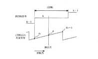
図3は多回転信号と1回転以内角度信号との関係を示す動作説明図である。
図3において、1回転以内角度信号は、この信号の分解能をdnとすると、回転体1回転に対して0から(dn−1)まで変化する角度信号となる。ある検出点における多回転量を含めた角度信号は、多回転信号が変化したときの1回転以内角度信号のデータdcを予め記憶しておき、検出点における1回転以内角度信号のデータdがdcより大きい場合は{(d−dc)/dn}を多回転信号kにプラスすることにより、dがdcより小さい場合は{(d+dn−dc)/dn}を多回転信号kにプラスすることにより得られる。
瞬時停電などにより外部電源が遮断された場合は、多回転磁界検出素子6および多回転信号処理回路7はバッテリにより電源が供給され、多回転量データを保持すると共に引き続き多回転量を検出する。多回転量の検出は1回転以内角度信号に比べて高い検出精度を要求しないので小さい電力で検出できる。なお、この時、磁界検出素子4および信号処理回路5には電源が供給されず、1回転以内角度信号は検出できないが、1X型エンコーダでは、1回転以内角度信号については、瞬時停電などにより外部電源が遮断されても、電源復帰後に1回転用磁界検出素子4検出信号から再生できる。
このように、本実施例では、1回転用磁界検出素子4と1回転信号処理回路6とで構成される1回転以内角度検出手段とは別に、多回転用磁界検出素子6と多回転信号処理回路7で構成される多回転検出手段を付加し、外部電源遮断時は、消費電力の小さい多回転検出手段のみにバックアップ電源を供給することにより、極めて小さい電力で多回転量を検出できる。本実施例ではバックアップ電源の消費電力を約0.3mWにすることが出来た。これは、従来の磁気式エンコーダ装置に多回転検出回路を付加し、磁界検出素子の信号を共用することで多回転量を検出する場合の消費電力の約1/500になる。
また、特別な多回転検出機構の追加することなく、多回転量を検出するための磁界検出素子として、小型で消費電力の小さい多回転用磁気抵抗素子6を1回転用磁界検出素子4と同一円周上の空隙部に配置したので、回転軸の軸方向、及び径方向への寸法増加は無く小型な構造を維持できる。
従って、幅広い分野に対して適用可能な磁気式エンコーダ装置を提供することができる。
なお、本実施例では永久磁石にフェライト系磁石を用いたが、Sm −Co 系磁石あるいはNe −Fe −B系磁石または前記各種磁石を高分子材料で結合した分散型複合磁石によって形成しても良い。
また、多回転信号処理回路7に増幅器71,72を用いて信号の調整を行っているが、コンパレータを用いても同様の効果が得られることは自明である。また、コンパレータを多回転信号処理回路7でなく磁界検出素子6の近傍に置くことも可能である。この場合、コンパレータの出力信号である2値化された信号を多回転信号処理回路7に送るため、耐ノイズ性を向上させることができる効果がある。Next, the operation of the first embodiment of the present invention will be described.
Since detection of an angle within one rotation is the same as in the prior art, only detection of the amount of multi-rotation will be described.
When the
FIG. 3 is an operation explanatory diagram showing the relationship between the multi-rotation signal and the angle signal within one rotation.
In FIG. 3, the angle signal within one rotation is an angle signal that changes from 0 to (dn-1) with respect to one rotation of the rotating body, where dn is the resolution of this signal. As the angle signal including the amount of multi-rotation at a certain detection point, the data dc of the angle signal within one rotation when the multi-rotation signal changes is stored in advance, and the data d of the angle signal within one rotation at the detection point is dc. When it is larger, {(d−dc) / dn} is added to the multi-rotation signal k, and when d is smaller than dc, {(d + dn−dc) / dn} is added to the multi-rotation signal k. can get.
When the external power supply is cut off due to an instantaneous power failure or the like, the multi-rotation magnetic
As described above, in this embodiment, the multi-rotation magnetic
Further, as a magnetic field detecting element for detecting the amount of multi-rotation without adding a special multi-rotation detecting mechanism, the multi-rotating
Therefore, it is possible to provide a magnetic encoder device applicable to a wide range of fields.
In this embodiment, the ferrite magnet is used as the permanent magnet. However, the permanent magnet may be formed of a Sm—Co magnet, a Ne—Fe—B magnet, or a dispersion type composite magnet in which the various magnets are combined with a polymer material. good.
In addition, although the signals are adjusted using the
図4は本発明の第2実施例を示す磁気式エンコーダ装置の斜視図である。
本実施例が第1実施例と異なる部分は、第1実施例では多回転用磁界検出素子6は円板状の永久磁石2の外周面に空隙を介して配置されているのに対し、本実施例では、永久磁石2の円板状の平面に空隙を介して配置している点である。なお、回転軸1が固定してある平面とは反対側の平面に配置した。
多回転用磁界検出素子6は、Am 相検出素子61とBm 相検出素子62の2個のホール素子からなり、回転体1の回転方向に互いに略90度位相をずらして、図示しない固定治具により固定体3に固定してある。永久磁石2の表面と多回転用磁界検出素子6のギャップは約1mm程度である。
なお、本実施例の動作については、第1実施例と同じであるのでその説明を省略する。
このように、本実施例では、多回転用磁界検出素子6を、回転体1とは反対側の永久磁石2の円板上の平面に空隙を介して配置したので、図示しないモータが回転体1と直結された場合、モータからの輻射熱を直接受けることが無く、小さい消費電流でも安定した検出ができる。
本実施例においても第1実施例と同様に、従来の磁気式エンコーダ装置の信号処理回路に多回転検出回路を付加し、1回転以内磁界検出素子の信号を共用することで多回転量を検出する場合と比較して消費電力を約1/500にすることが出来、バックアップ電源としてバッテリを使用した場合、このバッテリの交換時間を飛躍的に伸ばすことができる。FIG. 4 is a perspective view of a magnetic encoder device showing a second embodiment of the present invention.
The difference between the present embodiment and the first embodiment is that, in the first embodiment, the multi-rotation magnetic
The multi-rotation magnetic
Since the operation of this embodiment is the same as that of the first embodiment, the description thereof is omitted.
As described above, in this embodiment, the multi-rotation magnetic
Also in this embodiment, as in the first embodiment, a multi-rotation detection circuit is added to the signal processing circuit of the conventional magnetic encoder device, and the multi-rotation amount is detected by sharing the signal of the magnetic field detection element within one rotation. Compared with the case where it does, power consumption can be reduced to about 1/500, and when a battery is used as a backup power supply, the replacement time of this battery can be greatly extended.
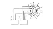
図5は、本発明の第3実施例を示す磁気式エンコーダ装置の斜視図である。
図5において、1’は回転体、2’は磁界発生ロータ、3’は固定体である。また、21はリング形状永久磁石、22はリング形状磁石21の外周に配置され磁性材料で構成されたリング形状磁気ヨークである。磁界発生ロータ2’はリング形状永久磁石21とリング形状磁気ヨーク22とで構成される。4はリング形状永久磁石21に空隙を介して対向し、固定体3’に取り付けられた1回転内の位置を検出する4つの1回転用磁界検出素子、5は磁界検出素子4からの信号を処理する1回転信号処理回路、6は前記リング形状永久磁石2に空隙を介して対向し、固定体3’に取り付けられた2つの多回転用磁界検出素子である。
リング形状永久磁石21は、フェライト系磁石で形成し、回転体1の軸に対して垂直方向と平行に一方向に磁化した2極の構成となっている。また、リング形状磁気ヨーク22は炭素鋼などの強磁性体で構成されている。磁界発生ロータ22は磁気抵抗を減少させ、1回転用磁界検出素子4および多回転用磁界検出素子6に磁界を集中させる効果があり、これにより磁界検出素子のSN比を向上させることができる。さらに外界の磁気ノイズを遮断する効果もある。材質は、強磁性体であれば良く、例えば炭素鋼などである。
1回転用磁界検出素子4は4個のホール効果素子からなり、永久磁石21の内周面に対して空隙を介して対向し、かつ互いに電気角で90度位相をずらしてA1相検出素子41とB1相検出素子42を設け、さらにA1相検出素子41に対して電気角で180度位相をずらしてA2相検出素子43を、B1相検出素子42に対して電気角で180度位相をずらしてB2相検出素子44を設けてある。
また、多回転用磁界検出素子6は磁気抵抗素子からなり、磁界発生ロータ2’に回転体1の径方向に空隙を介して対向し、かつ互いに電気角で略90度位相をずらしてAm相検出素子61とBm相検出素子62を設けてある。
1回転信号処理回路5および多回転処理回路7の構成については実施例1と同じであるのでその説明を省略する。
本実施例が実施例1と異なる点は、アウターロータ型のモータの多回転量を検出するため、回転体に固定された永久磁石をリング形状としさらに永久磁石の周囲にリング状の磁気ヨークを形成し、回転体の内側に配置されている固定体に1回転用磁界検出素子4および多回転用磁界検出素子6を配置した点である。FIG. 5 is a perspective view of a magnetic encoder device showing a third embodiment of the present invention.
In FIG. 5, 1 ′ is a rotating body, 2 ′ is a magnetic field generating rotor, and 3 ′ is a stationary body.
The ring-shaped
The one-rotation magnetic field detection element 4 is composed of four Hall effect elements, which are opposed to the inner peripheral surface of the
Further, the multi-rotation magnetic
Since the configurations of the one-rotation
This embodiment is different from the first embodiment in that a permanent magnet fixed to the rotating body is formed in a ring shape and a ring-shaped magnetic yoke is provided around the permanent magnet in order to detect the multi-rotation amount of the outer rotor type motor. The one-rotation magnetic field detection element 4 and the multi-rotation magnetic
次に、その動作について説明する。回転体1’の回転に伴って、磁界発生ロータ2’が回転する。磁界発生ロータ2’の発する磁界を1回転用磁界検出素子4にて検出し、1回転信号処理回路5にて1回転以内角度信号に変換する。また、磁界発生ロータ2’の発する磁界を磁界検出素子6にて検出し、信号処理回路7にて多回転信号に変換する。1回転以内角度信号および多回転信号の生成方法については実施例1と同じであるのでその説明を省略する。
本実施例では多回転量の検出機能の付加に伴う回転体の軸方向、及び径方向への寸法増加はないので小型な構造を維持でき、アウターロータ型の回転体に対して極めて小さい電力で多回転量を検出できる。
さらに磁界検出素子としてホール素子を用いることにより、寸法形状が小形でありながら(約2.5×1.5×0.6mm)、出力信号が大きく得られるので、耐ノイズ特性に優れる。また、ホール素子形状が小さいため、回転体の軸方向の厚さを薄く構成することができ、さらに径方向の厚みを薄く構成できるため中空径を大きくすることができ、中空形状に最適な構造となる。
なお、本実施例ではリング形状永久磁石にフェライト系磁石を用いたが、Sm−Co系磁石あるいはNe−Fe−B系磁石または前記各種磁石を高分子材料で結合した分散型複合磁石によって形成しても良い。Next, the operation will be described. The magnetic
In this embodiment, there is no increase in dimensions in the axial direction and radial direction of the rotating body due to the addition of a function for detecting the amount of multiple rotations, so that a small structure can be maintained, and with an extremely small electric power compared to the outer rotor type rotating body. Multi-rotation amount can be detected.
Further, by using a Hall element as the magnetic field detection element, a large output signal can be obtained while the size and shape are small (about 2.5 × 1.5 × 0.6 mm), and thus the noise resistance is excellent. In addition, since the Hall element shape is small, the axial thickness of the rotating body can be made thin, and further, the radial thickness can be made thin, so that the hollow diameter can be increased, and the structure optimal for the hollow shape It becomes.
In this embodiment, a ferrite magnet is used as the ring-shaped permanent magnet. However, the magnet is formed of a Sm—Co magnet, a Ne—Fe—B magnet, or a dispersion type composite magnet in which the various magnets are combined with a polymer material. May be.
図6は、本発明の第4実施例を示す磁気式エンコーダ装置の斜視図である。
本実施例が実施例3と異なっている点は、実施例3では多回転用磁界検出素子6を固定体3’の外周面に配置しているのに対し、本実施例では磁界発生ロータ2’の側面に回転体1’の軸方向に空隙を介して図示しない固定冶具により固定体3’に固定している点である。
なお、本実施例の動作については、第3実施例と同じであるのでその説明を省略する。
このように、本実施例では、アウターロータ型のモータに対して極めて小さい電力で多回転量を検出でき、多回転用磁界検出素子6を、回転体1’とは反対側の磁界発生ロータの平面に空隙を介して配置したので、実施例2と同様に、図示しないモータが回転体1’と直結された場合、モータからの輻射熱を直接受けることが無く、小さい消費電流でも安定した検出ができる。FIG. 6 is a perspective view of a magnetic encoder device showing a fourth embodiment of the present invention.
The difference between the third embodiment and the third embodiment is that in the third embodiment, the multi-rotation magnetic
Since the operation of this embodiment is the same as that of the third embodiment, the description thereof is omitted.
Thus, in this embodiment, the amount of multi-rotation can be detected with an extremely small electric power with respect to the outer rotor type motor, and the multi-rotation magnetic
図7は、本発明の第5実施例の固定体部の構成を示す図である。
図7において、31はリング形状固定体で、32は素子ホルダある。本実施例が実施例3と異なる点は、固定体の形状をリング形状とした点である。このようにすることにより中空構造をもつアウターロータ型のモータの多回転量を検出できる。また、リング形状固定体31の材質は強磁性体(例えば炭素鋼)とした。このようにすることにより実施例3のリング形状磁気ヨーク22の効果と同様に磁気抵抗を減少させ、磁界を1回転内の位置を検出する1回転用磁界検出素子4および多回転用磁界検出素子6に磁界を集中させる効果があり、検出信号のSN比を向上させることができ、外界の磁気ノイズを遮断する効果がある。また、リング形状固定体31と1回転用磁界検出素子4および多回転用磁界検出素子6の間に非磁性体で構成した素子ホルダを設けた。この素子ホルダにより、磁界検出素子の位置が容易になるだけでなく、位置精度も向上させることができる。
なお、本実施例の動作については、第3実施例と同じであるのでその説明を省略する。
このように、本実施例では、中空構造をもつアウターロータ型のモータに対して極めて小さい電力で多回転量を検出できる。FIG. 7 is a diagram showing the configuration of the fixed body portion of the fifth embodiment of the present invention.
In FIG. 7, 31 is a ring-shaped fixed body, and 32 is an element holder. This embodiment is different from the third embodiment in that the shape of the fixed body is a ring shape. By doing so, the multi-rotation amount of the outer rotor type motor having a hollow structure can be detected. The material of the ring-shaped
Since the operation of this embodiment is the same as that of the third embodiment, the description thereof is omitted.
As described above, in this embodiment, the multi-rotation amount can be detected with an extremely small electric power for an outer rotor type motor having a hollow structure.
本発明によって小型で低い消費電力で多回転量を検出することができるようになるので、絶対位置検出が必要な小型サーボモータに適用できる。 Since the present invention can detect the amount of multiple rotations with a small size and low power consumption, it can be applied to a small servo motor that requires absolute position detection.
Claims (4)
Translated fromJapanese前記永久磁石に空隙を介して対向し、固定体に取り付けられた磁界検出素子と、
前記磁界検出素子からの信号を処理する信号処理回路と、
を備え、
前記磁界検出素子は、
1回転以内の角度を検出する少なくとも2つの1回転用磁界検出素子と、
多回転量を検出する少なくとも2つの多回転用磁界検出素子と、
を有し、
前記信号処理回路は、
前記1回転用磁界検出素子の検出信号から1回転以内角度信号を生成する1回転信号処理回路と、
前記多回転用磁界検出素子の検出信号から多回転信号を生成する多回転信号処理回路と、を有し、
前記1回転信号処理回路が生成した1回転以内角度信号と、前記多回転信号処理回路が生成した多回転信号とに基づいて、
前記1回転以内角度信号の分解能をdnとし、検出点における該1回転以内角度信号をd(=0〜(dn−1))とし、前記多回転信号をkとし、該多回転信号が変化したときの該1回転以内角度信号のデータをdcとして予め記憶しておき、
d>dcであれば、k+(d−dc)/dnにより、
d<dcであれば、k+(d+dn−dc)/dnにより、
前記検出点における前記回転体の多回転量を含めた角度信号を生成することを特徴とする磁気式エンコーダ装置。A permanent magnet magnetized in one direction perpendicular to the rotation axis of the rotating body and fixed to the rotating body;
A magnetic field detection element that is opposed to the permanent magnet via a gap and is attached to afixed body ,
A signal processing circuit for processing a signal from the magnetic field detection element;
With
The magnetic field detecting element is
At least two one-turn magnetic field detecting elements for detecting an angle within one rotation;
At least two multi-rotation magnetic field detecting elements for detecting the multi-rotation amount;
Have
The signal processing circuit includes:
A one-rotation signal processing circuit for generating an angle signal within one rotation from the detection signal of the one-rotation magnetic field detecting element;
A multi-rotation signal processing circuit for generating a multi-rotation signal from a detection signal of the multi-rotation magnetic field detection element,
Based on the angle signal within one rotation generated by the one-turn signal processing circuit and the multi-turn signal generated by the multi-turn signal processing circuit,
The resolution of the angle signal within one rotation is dn, the angle signal within one rotation at the detection point is d (= 0 to (dn−1)), the multi-turn signal is k, and the multi-turn signal is changed. The angle signal data within one rotation at the time is stored in advance as dc,
If d> dc, k + (d−dc) / dn
If d <dc, k + (d + dn−dc) / dn
An angle signal including a multi-rotation amount of the rotating body at the detection point is generated.
Applications Claiming Priority (3)
| Application Number | Priority Date | Filing Date | Title |
|---|---|---|---|
| JP2004178124 | 2004-06-16 | ||
| JP2004178124 | 2004-06-16 | ||
| PCT/JP2005/008598WO2005124285A1 (en) | 2004-06-16 | 2005-05-11 | Magnetic encoder device |
Publications (2)
| Publication Number | Publication Date |
|---|---|
| JPWO2005124285A1 JPWO2005124285A1 (en) | 2008-04-10 |
| JP4678371B2true JP4678371B2 (en) | 2011-04-27 |
Family
ID=35509795
Family Applications (1)
| Application Number | Title | Priority Date | Filing Date |
|---|---|---|---|
| JP2006514669AExpired - Fee RelatedJP4678371B2 (en) | 2004-06-16 | 2005-05-11 | Magnetic encoder device |
Country Status (7)
| Country | Link |
|---|---|
| US (1) | US7595635B2 (en) |
| JP (1) | JP4678371B2 (en) |
| KR (2) | KR20070029700A (en) |
| CN (1) | CN1997876A (en) |
| DE (1) | DE112005001382B4 (en) |
| TW (1) | TW200617356A (en) |
| WO (1) | WO2005124285A1 (en) |
Families Citing this family (20)
| Publication number | Priority date | Publication date | Assignee | Title |
|---|---|---|---|---|
| US8427139B2 (en)* | 2005-05-25 | 2013-04-23 | Continental Tire Canada, Inc. | Dual pole magnet structure having two magnets 90 degrees out of phase for position sensing in an actuator |
| US7471080B2 (en)* | 2006-12-28 | 2008-12-30 | Harmonic Drive Systems Inc. | Magnetic absolute encoder |
| JP4899952B2 (en)* | 2007-03-09 | 2012-03-21 | 株式会社安川電機 | Magnetic absolute encoder |
| JP2009079925A (en)* | 2007-09-25 | 2009-04-16 | Mitsuba Corp | Encoder for motor |
| CN101836085B (en)* | 2007-10-25 | 2013-03-27 | 玛克西姆综合公司 | Method and apparatus for contactless sensing of rotational and angular positions using orientation tracking |
| FR2925749B1 (en)* | 2007-12-19 | 2010-03-05 | Schneider Electric Ind Sas | APPARATUS WITH CONTACTLESS ADJUSTING MEANS |
| CN101925800B (en)* | 2008-03-18 | 2013-04-17 | 三菱电机株式会社 | Rotation angle detection apparatus |
| US8305073B2 (en)* | 2008-04-23 | 2012-11-06 | Getrag Ford Transmissions Gmbh | Position sensor, position sensor arrangement and method of operating the same by measuring the angular orientation of a local magnetic field vector |
| US8947076B2 (en) | 2010-01-18 | 2015-02-03 | Bourns, Inc. | High resolution non-contacting multi-turn position sensor |
| WO2013139338A1 (en)* | 2012-03-20 | 2013-09-26 | Martin Professional A/S | Moving head light fixture with yoke and head position encoding means |
| US9606190B2 (en)* | 2012-12-21 | 2017-03-28 | Allegro Microsystems, Llc | Magnetic field sensor arrangements and associated methods |
| US9417295B2 (en) | 2012-12-21 | 2016-08-16 | Allegro Microsystems, Llc | Circuits and methods for processing signals generated by a circular vertical hall (CVH) sensing element in the presence of a multi-pole magnet |
| CN103925933B (en)* | 2013-01-11 | 2016-12-28 | 江苏多维科技有限公司 | A kind of multi-turn absolute magnetic encoder |
| WO2014135453A1 (en)* | 2013-03-05 | 2014-09-12 | Walter Mehnert | Magnetic linear or rotary encoder |
| JP6210284B2 (en)* | 2013-09-18 | 2017-10-11 | 株式会社ジェイテクト | Rotation angle detector |
| TWI640752B (en)* | 2016-11-30 | 2018-11-11 | 財團法人工業技術研究院 | Rotating sensing device and rotating sensing method |
| JP7270395B2 (en)* | 2019-01-25 | 2023-05-10 | ニデックインスツルメンツ株式会社 | Method for manufacturing magnet assembly, encoder and motor with encoder |
| CN109870177B (en)* | 2019-02-15 | 2021-10-08 | 广州极飞科技股份有限公司 | Magnetic encoder, calibration method and calibration device thereof, motor and unmanned aerial vehicle |
| US11761793B2 (en) | 2020-05-26 | 2023-09-19 | Analog Devices International Unlimited Company | Magnetic sensor package |
| US20250044125A1 (en)* | 2023-07-31 | 2025-02-06 | Analog Devices International Unlimited Company | Multi-turn magnetic sensing with rollover counting |
Citations (3)
| Publication number | Priority date | Publication date | Assignee | Title |
|---|---|---|---|---|
| JPH0662322U (en)* | 1993-02-04 | 1994-09-02 | 株式会社三協精機製作所 | Absolute encoder device |
| WO1999013296A1 (en)* | 1997-09-08 | 1999-03-18 | Kabushiki Kaisha Yaskawa Denki | Magnetic encoder |
| JP2002228486A (en)* | 2001-02-05 | 2002-08-14 | Yaskawa Electric Corp | Magnetic encoder |
Family Cites Families (9)
| Publication number | Priority date | Publication date | Assignee | Title |
|---|---|---|---|---|
| US5258735A (en)* | 1991-10-28 | 1993-11-02 | Allwine Jr Elmer C | Multi-pole composite magnet used in a magnetic encoder |
| EP0555961B1 (en)* | 1992-02-13 | 1997-07-16 | Japan Servo Co. Ltd. | Absolute encoder |
| DE9302758U1 (en) | 1993-02-25 | 1994-03-31 | Siemens AG, 80333 München | Magnetic angular position and speed encoder |
| DE4409892A1 (en)* | 1994-03-23 | 1995-09-28 | Bosch Gmbh Robert | Steering angle sensor |
| DE4440214C2 (en)* | 1994-11-10 | 1997-08-14 | Itt Ind Gmbh Deutsche | Encoder with Hall sensors |
| DE19817356A1 (en) | 1998-04-18 | 1999-10-21 | Bosch Gmbh Robert | Angle indicator for determining an angle between a sensor arrangement and a magnetic field |
| DE19820014A1 (en)* | 1998-05-06 | 1999-11-11 | Heidenhain Gmbh Dr Johannes | Multiturn code encoder |
| US6433536B1 (en)* | 1998-12-31 | 2002-08-13 | Pacsci Motion Control, Inc. | Apparatus for measuring the position of a movable member |
| DE50310186D1 (en)* | 2002-10-10 | 2008-09-04 | Ebm Papst St Georgen Gmbh & Co | Device for detecting the absolute angle of a shaft |
- 2005
- 2005-05-11CNCNA2005800188062Apatent/CN1997876A/enactivePending
- 2005-05-11USUS11/629,302patent/US7595635B2/ennot_activeExpired - Fee Related
- 2005-05-11WOPCT/JP2005/008598patent/WO2005124285A1/enactiveApplication Filing
- 2005-05-11KRKR1020067023124Apatent/KR20070029700A/ennot_activeCeased
- 2005-05-11KRKR1020087017033Apatent/KR20080077282A/ennot_activeWithdrawn
- 2005-05-11DEDE112005001382Tpatent/DE112005001382B4/ennot_activeExpired - Fee Related
- 2005-05-11JPJP2006514669Apatent/JP4678371B2/ennot_activeExpired - Fee Related
- 2005-05-19TWTW094116351Apatent/TW200617356A/enunknown
Patent Citations (3)
| Publication number | Priority date | Publication date | Assignee | Title |
|---|---|---|---|---|
| JPH0662322U (en)* | 1993-02-04 | 1994-09-02 | 株式会社三協精機製作所 | Absolute encoder device |
| WO1999013296A1 (en)* | 1997-09-08 | 1999-03-18 | Kabushiki Kaisha Yaskawa Denki | Magnetic encoder |
| JP2002228486A (en)* | 2001-02-05 | 2002-08-14 | Yaskawa Electric Corp | Magnetic encoder |
Also Published As
| Publication number | Publication date |
|---|---|
| KR20080077282A (en) | 2008-08-21 |
| JPWO2005124285A1 (en) | 2008-04-10 |
| DE112005001382T5 (en) | 2007-05-16 |
| US7595635B2 (en) | 2009-09-29 |
| WO2005124285A1 (en) | 2005-12-29 |
| TW200617356A (en) | 2006-06-01 |
| US20080054886A1 (en) | 2008-03-06 |
| DE112005001382B4 (en) | 2009-10-01 |
| CN1997876A (en) | 2007-07-11 |
| KR20070029700A (en) | 2007-03-14 |
Similar Documents
| Publication | Publication Date | Title |
|---|---|---|
| JP4678371B2 (en) | Magnetic encoder device | |
| JP5379748B2 (en) | Magnetic encoder | |
| JP5666886B2 (en) | Rotary encoder | |
| US6720763B1 (en) | Compact rotary magnetic position sensor having a sinusoidally varying output | |
| JP4858855B2 (en) | Rotation angle detector and rotating machine | |
| JP4621987B2 (en) | Magnetic encoder device and actuator | |
| WO2010029742A1 (en) | Rotation detecting device and bearing with rotation detecting device | |
| JP2004251831A (en) | Rotary angle detector | |
| EP1083406A2 (en) | Rotary position sensor | |
| JP2000065596A5 (en) | Magnetic encoder and motor with magnetic encoder | |
| JP2018105757A (en) | Magnetic encoder device | |
| JP5161010B2 (en) | Rotation detection device and bearing with rotation detection device | |
| JP4899410B2 (en) | Magnetic encoder device | |
| JP2018201299A (en) | Biaxial-integrated type motor | |
| JP5007922B2 (en) | Magnetic encoder device | |
| JP2007078534A (en) | Magnetic encoder device | |
| JP2006208049A (en) | Rotation angle detection apparatus | |
| JP4233920B2 (en) | Rotation angle detector | |
| JP4737372B2 (en) | Rotation angle detector | |
| JP4587656B2 (en) | Bearing with absolute encoder | |
| CN111693910A (en) | System for determining at least one rotational parameter of a rotating member | |
| JP2006300831A (en) | Rotation angle detector | |
| JP4001849B2 (en) | Magnetic rotary position sensor | |
| WO2010124573A1 (en) | Magnetically conductive ring | |
| JP2008014671A (en) | Magnetic encoder device |
Legal Events
| Date | Code | Title | Description |
|---|---|---|---|
| A621 | Written request for application examination | Free format text:JAPANESE INTERMEDIATE CODE: A621 Effective date:20080411 | |
| A521 | Request for written amendment filed | Free format text:JAPANESE INTERMEDIATE CODE: A523 Effective date:20091207 | |
| A131 | Notification of reasons for refusal | Free format text:JAPANESE INTERMEDIATE CODE: A131 Effective date:20100513 | |
| A521 | Request for written amendment filed | Free format text:JAPANESE INTERMEDIATE CODE: A523 Effective date:20100708 | |
| A131 | Notification of reasons for refusal | Free format text:JAPANESE INTERMEDIATE CODE: A131 Effective date:20100802 | |
| A521 | Request for written amendment filed | Free format text:JAPANESE INTERMEDIATE CODE: A523 Effective date:20100804 | |
| A131 | Notification of reasons for refusal | Free format text:JAPANESE INTERMEDIATE CODE: A131 Effective date:20101006 | |
| A521 | Request for written amendment filed | Free format text:JAPANESE INTERMEDIATE CODE: A523 Effective date:20101008 | |
| TRDD | Decision of grant or rejection written | ||
| A01 | Written decision to grant a patent or to grant a registration (utility model) | Free format text:JAPANESE INTERMEDIATE CODE: A01 Effective date:20110105 | |
| A01 | Written decision to grant a patent or to grant a registration (utility model) | Free format text:JAPANESE INTERMEDIATE CODE: A01 | |
| A61 | First payment of annual fees (during grant procedure) | Free format text:JAPANESE INTERMEDIATE CODE: A61 Effective date:20110118 | |
| R150 | Certificate of patent or registration of utility model | Free format text:JAPANESE INTERMEDIATE CODE: R150 | |
| FPAY | Renewal fee payment (event date is renewal date of database) | Free format text:PAYMENT UNTIL: 20140210 Year of fee payment:3 | |
| FPAY | Renewal fee payment (event date is renewal date of database) | Free format text:PAYMENT UNTIL: 20150210 Year of fee payment:4 | |
| LAPS | Cancellation because of no payment of annual fees |